US9618447B2 - Optical transmission cell with minimized spurious absorption - Google Patents
Optical transmission cell with minimized spurious absorption Download PDFInfo
- Publication number
- US9618447B2 US9618447B2 US14/660,762 US201514660762A US9618447B2 US 9618447 B2 US9618447 B2 US 9618447B2 US 201514660762 A US201514660762 A US 201514660762A US 9618447 B2 US9618447 B2 US 9618447B2
- Authority
- US
- United States
- Prior art keywords
- bore
- probe body
- probe
- measuring device
- spectroscopic measuring
- Prior art date
- Legal status (The legal status is an assumption and is not a legal conclusion. Google has not performed a legal analysis and makes no representation as to the accuracy of the status listed.)
- Expired - Fee Related
Links
Images


Classifications
-
- G—PHYSICS
- G01—MEASURING; TESTING
- G01N—INVESTIGATING OR ANALYSING MATERIALS BY DETERMINING THEIR CHEMICAL OR PHYSICAL PROPERTIES
- G01N21/00—Investigating or analysing materials by the use of optical means, i.e. using sub-millimetre waves, infrared, visible or ultraviolet light
- G01N21/17—Systems in which incident light is modified in accordance with the properties of the material investigated
- G01N21/25—Colour; Spectral properties, i.e. comparison of effect of material on the light at two or more different wavelengths or wavelength bands
- G01N21/31—Investigating relative effect of material at wavelengths characteristic of specific elements or molecules, e.g. atomic absorption spectrometry
- G01N21/35—Investigating relative effect of material at wavelengths characteristic of specific elements or molecules, e.g. atomic absorption spectrometry using infrared light
- G01N21/3504—Investigating relative effect of material at wavelengths characteristic of specific elements or molecules, e.g. atomic absorption spectrometry using infrared light for analysing gases, e.g. multi-gas analysis
-
- G—PHYSICS
- G01—MEASURING; TESTING
- G01N—INVESTIGATING OR ANALYSING MATERIALS BY DETERMINING THEIR CHEMICAL OR PHYSICAL PROPERTIES
- G01N21/00—Investigating or analysing materials by the use of optical means, i.e. using sub-millimetre waves, infrared, visible or ultraviolet light
- G01N21/01—Arrangements or apparatus for facilitating the optical investigation
- G01N21/03—Cuvette constructions
- G01N21/05—Flow-through cuvettes
-
- G—PHYSICS
- G01—MEASURING; TESTING
- G01N—INVESTIGATING OR ANALYSING MATERIALS BY DETERMINING THEIR CHEMICAL OR PHYSICAL PROPERTIES
- G01N21/00—Investigating or analysing materials by the use of optical means, i.e. using sub-millimetre waves, infrared, visible or ultraviolet light
- G01N21/17—Systems in which incident light is modified in accordance with the properties of the material investigated
- G01N21/25—Colour; Spectral properties, i.e. comparison of effect of material on the light at two or more different wavelengths or wavelength bands
- G01N21/31—Investigating relative effect of material at wavelengths characteristic of specific elements or molecules, e.g. atomic absorption spectrometry
- G01N21/35—Investigating relative effect of material at wavelengths characteristic of specific elements or molecules, e.g. atomic absorption spectrometry using infrared light
- G01N21/359—Investigating relative effect of material at wavelengths characteristic of specific elements or molecules, e.g. atomic absorption spectrometry using infrared light using near infrared light
-
- G—PHYSICS
- G01—MEASURING; TESTING
- G01N—INVESTIGATING OR ANALYSING MATERIALS BY DETERMINING THEIR CHEMICAL OR PHYSICAL PROPERTIES
- G01N33/00—Investigating or analysing materials by specific methods not covered by groups G01N1/00 - G01N31/00
- G01N33/0004—Gaseous mixtures, e.g. polluted air
- G01N33/0009—General constructional details of gas analysers, e.g. portable test equipment
- G01N33/0027—General constructional details of gas analysers, e.g. portable test equipment concerning the detector
- G01N33/0036—General constructional details of gas analysers, e.g. portable test equipment concerning the detector specially adapted to detect a particular component
- G01N33/0059—Avoiding interference of a gas with the gas to be measured
-
- G—PHYSICS
- G01—MEASURING; TESTING
- G01N—INVESTIGATING OR ANALYSING MATERIALS BY DETERMINING THEIR CHEMICAL OR PHYSICAL PROPERTIES
- G01N21/00—Investigating or analysing materials by the use of optical means, i.e. using sub-millimetre waves, infrared, visible or ultraviolet light
- G01N21/01—Arrangements or apparatus for facilitating the optical investigation
- G01N21/03—Cuvette constructions
- G01N2021/0389—Windows
-
- G—PHYSICS
- G01—MEASURING; TESTING
- G01N—INVESTIGATING OR ANALYSING MATERIALS BY DETERMINING THEIR CHEMICAL OR PHYSICAL PROPERTIES
- G01N21/00—Investigating or analysing materials by the use of optical means, i.e. using sub-millimetre waves, infrared, visible or ultraviolet light
- G01N21/01—Arrangements or apparatus for facilitating the optical investigation
- G01N21/03—Cuvette constructions
- G01N21/0317—High pressure cuvettes
-
- G—PHYSICS
- G01—MEASURING; TESTING
- G01N—INVESTIGATING OR ANALYSING MATERIALS BY DETERMINING THEIR CHEMICAL OR PHYSICAL PROPERTIES
- G01N2201/00—Features of devices classified in G01N21/00
- G01N2201/02—Mechanical
- G01N2201/022—Casings
- G01N2201/0227—Sealable enclosure
Definitions
- the invention relates generally to seals for spectroscopic measuring devices and, more particularly, to an optical transmission cell with minimized spurious absorption.
- Spectroscopic measuring devices are often used to analyze gasses.
- the purpose of this invention is to solve a problem that has arisen in the production of transmission cells for the analysis of gasses using near infrared spectroscopy.
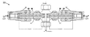
- FIG. 1 shows a transmission cell 110 , transmission cell system 110 , that is designed for analyzing a gas via operative connection to a spectrometer (not shown).
- the preferred transmission cell 110 consists of three major subassemblies: a central section or body 20 formed from a standard Swagelok® cross fitting, and first and second optical probes 40 , 50 which are directed toward each other across the central “cross” of the cross fitting 20 .
- the transmission cell 110 functions as follows: Near-IR radiation (which we will refer to as “NIR light” or just “light”) enters the system 110 by means of a transmitting fiber-optic cable (not shown, but alluded to with the inbound arrow labeled “NIR Light” on the left of FIG. 1 ). This fiber is terminated into the first optical probe 40 at a fiber-optic connector 41 .
- NIR light which we will refer to as “NIR light” or just “light”
- the light diverging from the end of the transmitting fiber is collected by a lens 42 so as to form a nominally collimated beam that is directed through an interior of the first probe 40 (region 1 ), through a measurement space in the cross fitting or cell body 20 (region 2 ), and then through an interior of the second probe 50 (region 3 ) where it collected by a second lens 52 and focused on a receiving optical fiber (not shown, but alluded to with the outbound arrow labeled “NIR Light” on the right side of FIG. 1 ).
- the receiving fiber would be located in connector 51 in the same manner that the transmitting fiber would be located in connector 41 .
- a total of four optical windows 44 , 45 , 54 , 55 are included in the preferred transmission cell 110 .
- the number is four because each probe 40 , 50 has two windows—a primary one and a secondary one.
- the first probe 40 has a primary window 44
- a secondary window 45 and the second probe 50 has a primary window 54 and a secondary window 55 .
- the two primary windows, 44 and 54 face one another from opposite sides of the nominal measurement region (region 2 ).
- the primary windows 44 , 54 are preferably sealed into the tips of the first and second probe bodies 40 , 50 using Axiom's patented welded sealing technique utilizing metal “C” rings 43 and 53 coated with a compliant material such as PTFE or Gold. These seals are designed to withstand the high pressures that may be present in the measurement region (region 2 ) and are explained in more detail in U.S. Pat. No. 6,587,192 hereby incorporated by reference as if fully set forth herein.
- the secondary windows 45 and 55 are located near the outer ends of the first and second probes 40 , 50 .
- the purpose of these secondary windows 45 , 55 is to isolate the probe interiors (regions 1 and 3 ) from contaminants that may be present in the ambient air.
- the space between the primary and secondary windows, i.e. between windows 44 and 45 and between windows 54 and 55 forms the interior of a given probe (regions 1 and 3 ).
- Each region has a diameter and a length which we will specify as Dp and Lp, respectively.
- the probes 40 , 50 are characterized by interiors, bores, or unfilled volumes 47 , 57 in regions 1 and 3 . It would be desirable to minimize Lp as much as possible to minimize the effects of any undesired gases in the probe body 40 or 50 . However, a practical minimum value is placed on Lp by the fact that the probes 40 , 50 must interconnect, e.g. have some length to mate to the mechanical dimensions of the Swagelok cross 20 with threaded fasteners (not separately numbered). The effects of undesired gasses within the interiors, bores, or unfilled volumes 47 , 57 of the probes 40 , 50 could also be minimized by continuously pumping on the probes 40 , 50 or purging them.
- the seals 43 , 53 have extremely low leak rates, the vapor in the cell body 20 is often at very high pressure relative to the pressures in the probe bodies 40 , 50 , such that over time small amounts of gas will inherently leak into the probe bodies 40 , 50 . This will create measurement problems because the measurements are very sensitive to small changes in the NIR spectrum.
- the invention resides in a spectroscopic measuring device for minimizing the effect of undesired gases that that interferes with measurement, comprising: a probe body that is inherently subject to leakage of undesired gas, the probe body having an axis, a distal end, a proximal end, and an interior; a primary window disposed at or near the distal end of the probe body and sealed with respect to the probe body; a secondary window located at or near the proximal end of the probe body and sealed with respect to the probe body, a bore defined by the interior of the probe body between the primary window and the secondary window, the bore having a nominal length and a nominal volume; a filler rod located in the bore and capable of transmitting light entering the primary window along the nominal length of the bore; and a void located adjacent to the filler rod, the void increasing the nominal volume of the bore.
- the invention resides in a spectroscopic measuring device for minimizing the effect of undesired gases that that interferes with measurement, comprising: a central section for receiving a gas to be analyzed; and first and second probe bodies that are inherently subject to leakage of undesired gas, wherein the first and second probe bodies are attached to the central section with one injecting light into the central portion and one collecting light from the central portion in order to measure a characteristic of a gas passing through the central section, and wherein each probe body comprises an axis, a distal end, a proximal end, and an interior; a primary window disposed at or near the distal end of the probe body and sealed with respect to the probe body; a secondary window located at or near the proximal end of the probe body and sealed with respect to the probe body, a bore defined by the interior of the probe body between the primary window and the secondary window, the bore having a nominal length and a nominal volume; a filler rod located in the bore and capable of transmitting light entering
- FIG. 1 is a schematic cross-sectional view of a transmission cell 110 of a first construction having a centrally located cell body 20 , first probe 40 with a bore 47 , and second probe 50 with a bore 57 , and where the bores 47 , 57 of the first and second probes 40 , 50 (Regions 1 and 3 ) are unfilled and subject to spurious absorption due to the presence of undesired gasses therein;
- FIG. 1 a is a simplified portion of the first probe 40 from FIG. 1 showing that its bore 47 has a length Lp and a diameter Dp, a glass rod 48 that fits tightly within the bore 47 , and the resulting assembly which has virtually no unfilled volume;
- FIG. 2 is a schematic cross-sectional view of a transmission cell 210 of a second modified construction where the reference numbers to items similar to corresponding items in FIG. 1 have been omitted for clarity, and where the bores 47 ′, 57 ′ of the first and second probes 40 , 50 (Regions 1 and 3 ) have been modified to contain filler rods 48 , 49 , and to have unfilled voids 49 , 59 of increased volume; and
- FIG. 2 a is a simplified portion of the first probe 40 from FIG. 2 showing that its bore 47 ′ has a length Lp and two diameters, a first diameter Dp 1 at a distal portion of the bore 47 ′ and an increased diameter Dp 2 along a portion of its length at a proximal portion of the bore 47 ′, a glass rod 48 that fits within the bore 47 ′, and the resulting assembly which includes a void or unfilled volume 49 .
- a c is an absorption coefficient for the material in the cell.
- the vapor in the cell body will be at a high pressure.
- D P pressure differential
- F rate of flow from the cell to the probe
- the absorbance is proportional to the pathlength and inversely proportional to the volume as long as the pressure in the probe remains low compared to that in the measurement cell.
- the second transmission cell system 210 of FIG. 2 substantially reduces the effects of gas leakage into the probe bodies 40 , 50 by minimizing the ratio of pathlength to probe volume, i.e. (L p /V p ).
- the first step is to place a glass rod 48 , 58 in the probe body 40 , 50 ) so that most of the optical path is within the rod 48 , 58 rather than in to open volume of the probe 40 , 50 .
- the simplest way to do this is to slip a tight-fitting rod 48 , 58 into the bore 47 , 57 of the previously existing probes.
- L u is the length of the unfilled volume 49 and, again, D p is the inner diameter of the probe.
- the design illustrated in FIG. 2 increases the probe volume by about two orders of magnitude compared to the volume between the ends of the rod and the probe windows. It should thus reduce the absorbance by two orders of magnitude.
- the glass rod is indicated by 48 or 58 .
- the increased volume provided by discrete or annular voids located adjacent to the filler rod 48 or 58 is indicated by 49 or 59 .
- the probe volume can also be increased by creating an additional volume away from the main body of the probe. This can be done, for example, by providing a significant length of tubing between the probe bore 47 , 57 and the valve used for sealing the probe.
Landscapes
- Physics & Mathematics (AREA)
- Chemical & Material Sciences (AREA)
- Health & Medical Sciences (AREA)
- Life Sciences & Earth Sciences (AREA)
- General Physics & Mathematics (AREA)
- Analytical Chemistry (AREA)
- Biochemistry (AREA)
- General Health & Medical Sciences (AREA)
- Immunology (AREA)
- Pathology (AREA)
- Spectroscopy & Molecular Physics (AREA)
- Engineering & Computer Science (AREA)
- Combustion & Propulsion (AREA)
- Food Science & Technology (AREA)
- Medicinal Chemistry (AREA)
- Investigating Or Analysing Materials By Optical Means (AREA)
Abstract
Description
A c =a c L c C c, where the subscript “c” refers to the cell. Eq. 1
T=−log10 A. Eq. 2
P=CRT, Eq. 3
F=K
where “K” is a constant that takes into consideration the cross sectional area and the leakage characteristics of the window seal.
P p(t)=(K
Where Vp is the volume of the probe body.
C p(t)=P p(t)/RT=(K′
A p(t)=a p L p C p(t)=a p L p(K′
V u=(pD p 2/4)L u, Eq. 8
Lu/Vu=4/πD p 2
Claims (8)
Priority Applications (1)
| Application Number | Priority Date | Filing Date | Title |
|---|---|---|---|
| US14/660,762 US9618447B2 (en) | 2014-03-17 | 2015-03-17 | Optical transmission cell with minimized spurious absorption |
Applications Claiming Priority (2)
| Application Number | Priority Date | Filing Date | Title |
|---|---|---|---|
| US201461954464P | 2014-03-17 | 2014-03-17 | |
| US14/660,762 US9618447B2 (en) | 2014-03-17 | 2015-03-17 | Optical transmission cell with minimized spurious absorption |
Publications (2)
| Publication Number | Publication Date |
|---|---|
| US20150260638A1 US20150260638A1 (en) | 2015-09-17 |
| US9618447B2 true US9618447B2 (en) | 2017-04-11 |
Family
ID=54068569
Family Applications (1)
| Application Number | Title | Priority Date | Filing Date |
|---|---|---|---|
| US14/660,762 Expired - Fee Related US9618447B2 (en) | 2014-03-17 | 2015-03-17 | Optical transmission cell with minimized spurious absorption |
Country Status (1)
| Country | Link |
|---|---|
| US (1) | US9618447B2 (en) |
Citations (2)
| Publication number | Priority date | Publication date | Assignee | Title |
|---|---|---|---|---|
| US4507954A (en) * | 1983-06-27 | 1985-04-02 | Tubing Testors, Inc. | Wraparound used for testing tubing with premixed gases |
| US5442437A (en) * | 1993-09-13 | 1995-08-15 | Atlantic Richfield Company | Sample cell and probe for spectrophotometer |
-
2015
- 2015-03-17 US US14/660,762 patent/US9618447B2/en not_active Expired - Fee Related
Patent Citations (2)
| Publication number | Priority date | Publication date | Assignee | Title |
|---|---|---|---|---|
| US4507954A (en) * | 1983-06-27 | 1985-04-02 | Tubing Testors, Inc. | Wraparound used for testing tubing with premixed gases |
| US5442437A (en) * | 1993-09-13 | 1995-08-15 | Atlantic Richfield Company | Sample cell and probe for spectrophotometer |
Also Published As
| Publication number | Publication date |
|---|---|
| US20150260638A1 (en) | 2015-09-17 |
Similar Documents
| Publication | Publication Date | Title |
|---|---|---|
| US9091151B2 (en) | Downhole optical radiometry tool | |
| US9651710B2 (en) | Downhole fluid properties analysis device and tools comprising such a device | |
| US8427638B2 (en) | Optical measurement device including a multi-component sealing assembly | |
| KR20210127719A (en) | Spectroscopic devices, systems, and methods for optical sensing of molecular species | |
| CN102656441A (en) | Spectrometer with verification unit | |
| FR3047314A1 (en) | OPTICAL PROBE FOR ANALYZING WELL BACKGROUND FLUID PROPERTIES COMPRISING A REMOVABLE OPTICAL POINT. | |
| US20020171836A1 (en) | Flow cells utilizing photometric techniques | |
| JP7412511B2 (en) | Method and apparatus for monitoring the quality of gas phase media | |
| JP2008309785A (en) | Attenuated total reflection sensor | |
| CN104777099B (en) | Improved measurement colour comparator | |
| MX2015003387A (en) | Method and system for determining energy content and detecting contaminants in a fluid stream. | |
| US20180156715A1 (en) | Hollow fibre waveguide gas cells | |
| CN107533003A (en) | Spectrometer with random beam distribution | |
| FR3058451A1 (en) | DEVICE AND METHOD FOR OPTICAL MONITORING OF CHEMICAL COMPOSITION IN WELL BOTTOM, WELL BOTTOM ASSEMBLY AND MEASURING TOOL COMPRISING SUCH A DEVICE | |
| US7886821B2 (en) | Apparatus and method for determining fluid properties | |
| US9618447B2 (en) | Optical transmission cell with minimized spurious absorption | |
| JP2016099311A (en) | Sample measuring device | |
| CN210487587U (en) | Calibration device for gas laser absorption spectrum measurement | |
| US20110292677A1 (en) | Highly inert fluid-handling optical systems | |
| CN101281129B (en) | On-position type gas analysis system with on-position calibration function | |
| JP2005329330A (en) | High temperature / high pressure container window structure | |
| EP3686578B1 (en) | Inspecting method and inspection system | |
| Huber et al. | A selective, miniaturized, low-cost detection element for a photoacoustic CO2 sensor for room climate monitoring | |
| JP2014115198A (en) | Gas sampling bag and laser measuring device | |
| Padilla-Viquez et al. | Traceable $\hbox {CO} _ {2}\hbox {-}{\rm R}(12) $ Line Intensity for Laser-Spectroscopy-Based Gas Analysis Near 2$\mu\hbox {m} $ |
Legal Events
| Date | Code | Title | Description |
|---|---|---|---|
| AS | Assignment |
Owner name: AXIOM ANALYTICAL, INC., CALIFORNIA Free format text: ASSIGNMENT OF ASSIGNORS INTEREST;ASSIGNORS:DOYLE, WALTER M;JENNINGS, NORMAN A;REEL/FRAME:035185/0987 Effective date: 20150317 |
|
| AS | Assignment |
Owner name: HELLMA HOLDING GMBH, GERMANY Free format text: ASSIGNMENT OF ASSIGNORS INTEREST;ASSIGNOR:AXIOM ANALYTICAL, INC.;REEL/FRAME:040165/0785 Effective date: 20160228 |
|
| STCF | Information on status: patent grant |
Free format text: PATENTED CASE |
|
| FEPP | Fee payment procedure |
Free format text: MAINTENANCE FEE REMINDER MAILED (ORIGINAL EVENT CODE: REM.); ENTITY STATUS OF PATENT OWNER: SMALL ENTITY |
|
| LAPS | Lapse for failure to pay maintenance fees |
Free format text: PATENT EXPIRED FOR FAILURE TO PAY MAINTENANCE FEES (ORIGINAL EVENT CODE: EXP.); ENTITY STATUS OF PATENT OWNER: SMALL ENTITY |
|
| STCH | Information on status: patent discontinuation |
Free format text: PATENT EXPIRED DUE TO NONPAYMENT OF MAINTENANCE FEES UNDER 37 CFR 1.362 |
|
| FP | Lapsed due to failure to pay maintenance fee |
Effective date: 20210411 |