US9618014B2 - Implement system having hydraulic start assist - Google Patents
Implement system having hydraulic start assist Download PDFInfo
- Publication number
- US9618014B2 US9618014B2 US14/263,710 US201414263710A US9618014B2 US 9618014 B2 US9618014 B2 US 9618014B2 US 201414263710 A US201414263710 A US 201414263710A US 9618014 B2 US9618014 B2 US 9618014B2
- Authority
- US
- United States
- Prior art keywords
- accumulator
- engine
- fluid
- actuator
- swing
- Prior art date
- Legal status (The legal status is an assumption and is not a legal conclusion. Google has not performed a legal analysis and makes no representation as to the accuracy of the status listed.)
- Active, expires
Links
- 239000012530 fluid Substances 0.000 claims abstract description 293
- 230000033001 locomotion Effects 0.000 description 28
- 230000004044 response Effects 0.000 description 16
- 239000007789 gas Substances 0.000 description 10
- 230000006870 function Effects 0.000 description 9
- 238000004891 communication Methods 0.000 description 5
- 238000006073 displacement reaction Methods 0.000 description 5
- 239000000463 material Substances 0.000 description 5
- 238000000034 method Methods 0.000 description 5
- 238000011084 recovery Methods 0.000 description 5
- XKRFYHLGVUSROY-UHFFFAOYSA-N Argon Chemical compound [Ar] XKRFYHLGVUSROY-UHFFFAOYSA-N 0.000 description 4
- IJGRMHOSHXDMSA-UHFFFAOYSA-N Atomic nitrogen Chemical compound N#N IJGRMHOSHXDMSA-UHFFFAOYSA-N 0.000 description 4
- 230000001133 acceleration Effects 0.000 description 4
- 239000000446 fuel Substances 0.000 description 3
- 230000001105 regulatory effect Effects 0.000 description 3
- 229910052786 argon Inorganic materials 0.000 description 2
- 238000007599 discharging Methods 0.000 description 2
- 239000001307 helium Substances 0.000 description 2
- 229910052734 helium Inorganic materials 0.000 description 2
- SWQJXJOGLNCZEY-UHFFFAOYSA-N helium atom Chemical compound [He] SWQJXJOGLNCZEY-UHFFFAOYSA-N 0.000 description 2
- 238000005461 lubrication Methods 0.000 description 2
- 239000012528 membrane Substances 0.000 description 2
- 229910052757 nitrogen Inorganic materials 0.000 description 2
- 239000003921 oil Substances 0.000 description 2
- 230000008929 regeneration Effects 0.000 description 2
- 238000011069 regeneration method Methods 0.000 description 2
- 239000013589 supplement Substances 0.000 description 2
- 239000002699 waste material Substances 0.000 description 2
- 230000004913 activation Effects 0.000 description 1
- 238000009412 basement excavation Methods 0.000 description 1
- 230000009286 beneficial effect Effects 0.000 description 1
- 230000005540 biological transmission Effects 0.000 description 1
- 230000001276 controlling effect Effects 0.000 description 1
- 238000001816 cooling Methods 0.000 description 1
- 230000008878 coupling Effects 0.000 description 1
- 238000010168 coupling process Methods 0.000 description 1
- 238000005859 coupling reaction Methods 0.000 description 1
- 239000010720 hydraulic oil Substances 0.000 description 1
- 230000003993 interaction Effects 0.000 description 1
- 230000007257 malfunction Effects 0.000 description 1
- 239000000203 mixture Substances 0.000 description 1
- 230000004048 modification Effects 0.000 description 1
- 238000012986 modification Methods 0.000 description 1
- 230000007935 neutral effect Effects 0.000 description 1
- 230000008569 process Effects 0.000 description 1
- 230000009467 reduction Effects 0.000 description 1
- 230000003252 repetitive effect Effects 0.000 description 1
- 238000011144 upstream manufacturing Methods 0.000 description 1
Images


Classifications
-
- F—MECHANICAL ENGINEERING; LIGHTING; HEATING; WEAPONS; BLASTING
- F15—FLUID-PRESSURE ACTUATORS; HYDRAULICS OR PNEUMATICS IN GENERAL
- F15B—SYSTEMS ACTING BY MEANS OF FLUIDS IN GENERAL; FLUID-PRESSURE ACTUATORS, e.g. SERVOMOTORS; DETAILS OF FLUID-PRESSURE SYSTEMS, NOT OTHERWISE PROVIDED FOR
- F15B1/00—Installations or systems with accumulators; Supply reservoir or sump assemblies
- F15B1/02—Installations or systems with accumulators
- F15B1/024—Installations or systems with accumulators used as a supplementary power source, e.g. to store energy in idle periods to balance pump load
-
- B—PERFORMING OPERATIONS; TRANSPORTING
- B60—VEHICLES IN GENERAL
- B60K—ARRANGEMENT OR MOUNTING OF PROPULSION UNITS OR OF TRANSMISSIONS IN VEHICLES; ARRANGEMENT OR MOUNTING OF PLURAL DIVERSE PRIME-MOVERS IN VEHICLES; AUXILIARY DRIVES FOR VEHICLES; INSTRUMENTATION OR DASHBOARDS FOR VEHICLES; ARRANGEMENTS IN CONNECTION WITH COOLING, AIR INTAKE, GAS EXHAUST OR FUEL SUPPLY OF PROPULSION UNITS IN VEHICLES
- B60K6/00—Arrangement or mounting of plural diverse prime-movers for mutual or common propulsion, e.g. hybrid propulsion systems comprising electric motors and internal combustion engines ; Control systems therefor, i.e. systems controlling two or more prime movers, or controlling one of these prime movers and any of the transmission, drive or drive units Informative references: mechanical gearings with secondary electric drive F16H3/72; arrangements for handling mechanical energy structurally associated with the dynamo-electric machine H02K7/00; machines comprising structurally interrelated motor and generator parts H02K51/00; dynamo-electric machines not otherwise provided for in H02K see H02K99/00
- B60K6/08—Prime-movers comprising combustion engines and mechanical or fluid energy storing means
- B60K6/12—Prime-movers comprising combustion engines and mechanical or fluid energy storing means by means of a chargeable fluidic accumulator
-
- E—FIXED CONSTRUCTIONS
- E02—HYDRAULIC ENGINEERING; FOUNDATIONS; SOIL SHIFTING
- E02F—DREDGING; SOIL-SHIFTING
- E02F3/00—Dredgers; Soil-shifting machines
- E02F3/04—Dredgers; Soil-shifting machines mechanically-driven
- E02F3/28—Dredgers; Soil-shifting machines mechanically-driven with digging tools mounted on a dipper- or bucket-arm, i.e. there is either one arm or a pair of arms, e.g. dippers, buckets
- E02F3/36—Component parts
- E02F3/42—Drives for dippers, buckets, dipper-arms or bucket-arms
- E02F3/425—Drive systems for dipper-arms, backhoes or the like
-
- E—FIXED CONSTRUCTIONS
- E02—HYDRAULIC ENGINEERING; FOUNDATIONS; SOIL SHIFTING
- E02F—DREDGING; SOIL-SHIFTING
- E02F9/00—Component parts of dredgers or soil-shifting machines, not restricted to one of the kinds covered by groups E02F3/00 - E02F7/00
- E02F9/20—Drives; Control devices
- E02F9/22—Hydraulic or pneumatic drives
- E02F9/2217—Hydraulic or pneumatic drives with energy recovery arrangements, e.g. using accumulators, flywheels
-
- F—MECHANICAL ENGINEERING; LIGHTING; HEATING; WEAPONS; BLASTING
- F02—COMBUSTION ENGINES; HOT-GAS OR COMBUSTION-PRODUCT ENGINE PLANTS
- F02N—STARTING OF COMBUSTION ENGINES; STARTING AIDS FOR SUCH ENGINES, NOT OTHERWISE PROVIDED FOR
- F02N11/00—Starting of engines by means of electric motors
-
- F—MECHANICAL ENGINEERING; LIGHTING; HEATING; WEAPONS; BLASTING
- F02—COMBUSTION ENGINES; HOT-GAS OR COMBUSTION-PRODUCT ENGINE PLANTS
- F02N—STARTING OF COMBUSTION ENGINES; STARTING AIDS FOR SUCH ENGINES, NOT OTHERWISE PROVIDED FOR
- F02N7/00—Starting apparatus having fluid-driven auxiliary engines or apparatus
- F02N7/08—Starting apparatus having fluid-driven auxiliary engines or apparatus the engines being of rotary type
-
- F—MECHANICAL ENGINEERING; LIGHTING; HEATING; WEAPONS; BLASTING
- F04—POSITIVE - DISPLACEMENT MACHINES FOR LIQUIDS; PUMPS FOR LIQUIDS OR ELASTIC FLUIDS
- F04B—POSITIVE-DISPLACEMENT MACHINES FOR LIQUIDS; PUMPS
- F04B17/00—Pumps characterised by combination with, or adaptation to, specific driving engines or motors
- F04B17/05—Pumps characterised by combination with, or adaptation to, specific driving engines or motors driven by internal-combustion engines
-
- F—MECHANICAL ENGINEERING; LIGHTING; HEATING; WEAPONS; BLASTING
- F04—POSITIVE - DISPLACEMENT MACHINES FOR LIQUIDS; PUMPS FOR LIQUIDS OR ELASTIC FLUIDS
- F04B—POSITIVE-DISPLACEMENT MACHINES FOR LIQUIDS; PUMPS
- F04B35/00—Piston pumps specially adapted for elastic fluids and characterised by the driving means to their working members, or by combination with, or adaptation to, specific driving engines or motors, not otherwise provided for
- F04B35/002—Piston pumps specially adapted for elastic fluids and characterised by the driving means to their working members, or by combination with, or adaptation to, specific driving engines or motors, not otherwise provided for driven by internal combustion engines
-
- F—MECHANICAL ENGINEERING; LIGHTING; HEATING; WEAPONS; BLASTING
- F15—FLUID-PRESSURE ACTUATORS; HYDRAULICS OR PNEUMATICS IN GENERAL
- F15B—SYSTEMS ACTING BY MEANS OF FLUIDS IN GENERAL; FLUID-PRESSURE ACTUATORS, e.g. SERVOMOTORS; DETAILS OF FLUID-PRESSURE SYSTEMS, NOT OTHERWISE PROVIDED FOR
- F15B21/00—Common features of fluid actuator systems; Fluid-pressure actuator systems or details thereof, not covered by any other group of this subclass
- F15B21/14—Energy-recuperation means
-
- B—PERFORMING OPERATIONS; TRANSPORTING
- B60—VEHICLES IN GENERAL
- B60K—ARRANGEMENT OR MOUNTING OF PROPULSION UNITS OR OF TRANSMISSIONS IN VEHICLES; ARRANGEMENT OR MOUNTING OF PLURAL DIVERSE PRIME-MOVERS IN VEHICLES; AUXILIARY DRIVES FOR VEHICLES; INSTRUMENTATION OR DASHBOARDS FOR VEHICLES; ARRANGEMENTS IN CONNECTION WITH COOLING, AIR INTAKE, GAS EXHAUST OR FUEL SUPPLY OF PROPULSION UNITS IN VEHICLES
- B60K6/00—Arrangement or mounting of plural diverse prime-movers for mutual or common propulsion, e.g. hybrid propulsion systems comprising electric motors and internal combustion engines ; Control systems therefor, i.e. systems controlling two or more prime movers, or controlling one of these prime movers and any of the transmission, drive or drive units Informative references: mechanical gearings with secondary electric drive F16H3/72; arrangements for handling mechanical energy structurally associated with the dynamo-electric machine H02K7/00; machines comprising structurally interrelated motor and generator parts H02K51/00; dynamo-electric machines not otherwise provided for in H02K see H02K99/00
- B60K6/08—Prime-movers comprising combustion engines and mechanical or fluid energy storing means
- B60K6/12—Prime-movers comprising combustion engines and mechanical or fluid energy storing means by means of a chargeable fluidic accumulator
- B60K2006/126—Prime-movers comprising combustion engines and mechanical or fluid energy storing means by means of a chargeable fluidic accumulator the hydraulic accumulator starts the engine
-
- B—PERFORMING OPERATIONS; TRANSPORTING
- B60—VEHICLES IN GENERAL
- B60W—CONJOINT CONTROL OF VEHICLE SUB-UNITS OF DIFFERENT TYPE OR DIFFERENT FUNCTION; CONTROL SYSTEMS SPECIALLY ADAPTED FOR HYBRID VEHICLES; ROAD VEHICLE DRIVE CONTROL SYSTEMS FOR PURPOSES NOT RELATED TO THE CONTROL OF A PARTICULAR SUB-UNIT
- B60W2300/00—Indexing codes relating to the type of vehicle
- B60W2300/17—Construction vehicles, e.g. graders, excavators
-
- F—MECHANICAL ENGINEERING; LIGHTING; HEATING; WEAPONS; BLASTING
- F02—COMBUSTION ENGINES; HOT-GAS OR COMBUSTION-PRODUCT ENGINE PLANTS
- F02N—STARTING OF COMBUSTION ENGINES; STARTING AIDS FOR SUCH ENGINES, NOT OTHERWISE PROVIDED FOR
- F02N2300/00—Control related aspects of engine starting
- F02N2300/20—Control related aspects of engine starting characterised by the control method
- F02N2300/2002—Control related aspects of engine starting characterised by the control method using different starting modes, methods, or actuators depending on circumstances, e.g. engine temperature or component wear
-
- F—MECHANICAL ENGINEERING; LIGHTING; HEATING; WEAPONS; BLASTING
- F15—FLUID-PRESSURE ACTUATORS; HYDRAULICS OR PNEUMATICS IN GENERAL
- F15B—SYSTEMS ACTING BY MEANS OF FLUIDS IN GENERAL; FLUID-PRESSURE ACTUATORS, e.g. SERVOMOTORS; DETAILS OF FLUID-PRESSURE SYSTEMS, NOT OTHERWISE PROVIDED FOR
- F15B2211/00—Circuits for servomotor systems
- F15B2211/20—Fluid pressure source, e.g. accumulator or variable axial piston pump
- F15B2211/205—Systems with pumps
- F15B2211/20507—Type of prime mover
- F15B2211/20523—Internal combustion engine
-
- F—MECHANICAL ENGINEERING; LIGHTING; HEATING; WEAPONS; BLASTING
- F15—FLUID-PRESSURE ACTUATORS; HYDRAULICS OR PNEUMATICS IN GENERAL
- F15B—SYSTEMS ACTING BY MEANS OF FLUIDS IN GENERAL; FLUID-PRESSURE ACTUATORS, e.g. SERVOMOTORS; DETAILS OF FLUID-PRESSURE SYSTEMS, NOT OTHERWISE PROVIDED FOR
- F15B2211/00—Circuits for servomotor systems
- F15B2211/20—Fluid pressure source, e.g. accumulator or variable axial piston pump
- F15B2211/205—Systems with pumps
- F15B2211/2053—Type of pump
- F15B2211/20546—Type of pump variable capacity
-
- F—MECHANICAL ENGINEERING; LIGHTING; HEATING; WEAPONS; BLASTING
- F15—FLUID-PRESSURE ACTUATORS; HYDRAULICS OR PNEUMATICS IN GENERAL
- F15B—SYSTEMS ACTING BY MEANS OF FLUIDS IN GENERAL; FLUID-PRESSURE ACTUATORS, e.g. SERVOMOTORS; DETAILS OF FLUID-PRESSURE SYSTEMS, NOT OTHERWISE PROVIDED FOR
- F15B2211/00—Circuits for servomotor systems
- F15B2211/20—Fluid pressure source, e.g. accumulator or variable axial piston pump
- F15B2211/21—Systems with pressure sources other than pumps, e.g. with a pyrotechnical charge
- F15B2211/212—Systems with pressure sources other than pumps, e.g. with a pyrotechnical charge the pressure sources being accumulators
-
- F—MECHANICAL ENGINEERING; LIGHTING; HEATING; WEAPONS; BLASTING
- F15—FLUID-PRESSURE ACTUATORS; HYDRAULICS OR PNEUMATICS IN GENERAL
- F15B—SYSTEMS ACTING BY MEANS OF FLUIDS IN GENERAL; FLUID-PRESSURE ACTUATORS, e.g. SERVOMOTORS; DETAILS OF FLUID-PRESSURE SYSTEMS, NOT OTHERWISE PROVIDED FOR
- F15B2211/00—Circuits for servomotor systems
- F15B2211/70—Output members, e.g. hydraulic motors or cylinders or control therefor
- F15B2211/705—Output members, e.g. hydraulic motors or cylinders or control therefor characterised by the type of output members or actuators
- F15B2211/7051—Linear output members
- F15B2211/7053—Double-acting output members
-
- F—MECHANICAL ENGINEERING; LIGHTING; HEATING; WEAPONS; BLASTING
- F15—FLUID-PRESSURE ACTUATORS; HYDRAULICS OR PNEUMATICS IN GENERAL
- F15B—SYSTEMS ACTING BY MEANS OF FLUIDS IN GENERAL; FLUID-PRESSURE ACTUATORS, e.g. SERVOMOTORS; DETAILS OF FLUID-PRESSURE SYSTEMS, NOT OTHERWISE PROVIDED FOR
- F15B2211/00—Circuits for servomotor systems
- F15B2211/70—Output members, e.g. hydraulic motors or cylinders or control therefor
- F15B2211/705—Output members, e.g. hydraulic motors or cylinders or control therefor characterised by the type of output members or actuators
- F15B2211/7058—Rotary output members
-
- F—MECHANICAL ENGINEERING; LIGHTING; HEATING; WEAPONS; BLASTING
- F15—FLUID-PRESSURE ACTUATORS; HYDRAULICS OR PNEUMATICS IN GENERAL
- F15B—SYSTEMS ACTING BY MEANS OF FLUIDS IN GENERAL; FLUID-PRESSURE ACTUATORS, e.g. SERVOMOTORS; DETAILS OF FLUID-PRESSURE SYSTEMS, NOT OTHERWISE PROVIDED FOR
- F15B2211/00—Circuits for servomotor systems
- F15B2211/70—Output members, e.g. hydraulic motors or cylinders or control therefor
- F15B2211/71—Multiple output members, e.g. multiple hydraulic motors or cylinders
- F15B2211/7135—Combinations of output members of different types, e.g. single-acting cylinders with rotary motors
-
- F—MECHANICAL ENGINEERING; LIGHTING; HEATING; WEAPONS; BLASTING
- F15—FLUID-PRESSURE ACTUATORS; HYDRAULICS OR PNEUMATICS IN GENERAL
- F15B—SYSTEMS ACTING BY MEANS OF FLUIDS IN GENERAL; FLUID-PRESSURE ACTUATORS, e.g. SERVOMOTORS; DETAILS OF FLUID-PRESSURE SYSTEMS, NOT OTHERWISE PROVIDED FOR
- F15B2211/00—Circuits for servomotor systems
- F15B2211/80—Other types of control related to particular problems or conditions
- F15B2211/85—Control during special operating conditions
- F15B2211/851—Control during special operating conditions during starting
-
- F—MECHANICAL ENGINEERING; LIGHTING; HEATING; WEAPONS; BLASTING
- F15—FLUID-PRESSURE ACTUATORS; HYDRAULICS OR PNEUMATICS IN GENERAL
- F15B—SYSTEMS ACTING BY MEANS OF FLUIDS IN GENERAL; FLUID-PRESSURE ACTUATORS, e.g. SERVOMOTORS; DETAILS OF FLUID-PRESSURE SYSTEMS, NOT OTHERWISE PROVIDED FOR
- F15B2211/00—Circuits for servomotor systems
- F15B2211/80—Other types of control related to particular problems or conditions
- F15B2211/85—Control during special operating conditions
- F15B2211/853—Control during special operating conditions during stopping
-
- Y—GENERAL TAGGING OF NEW TECHNOLOGICAL DEVELOPMENTS; GENERAL TAGGING OF CROSS-SECTIONAL TECHNOLOGIES SPANNING OVER SEVERAL SECTIONS OF THE IPC; TECHNICAL SUBJECTS COVERED BY FORMER USPC CROSS-REFERENCE ART COLLECTIONS [XRACs] AND DIGESTS
- Y02—TECHNOLOGIES OR APPLICATIONS FOR MITIGATION OR ADAPTATION AGAINST CLIMATE CHANGE
- Y02T—CLIMATE CHANGE MITIGATION TECHNOLOGIES RELATED TO TRANSPORTATION
- Y02T10/00—Road transport of goods or passengers
- Y02T10/60—Other road transportation technologies with climate change mitigation effect
- Y02T10/62—Hybrid vehicles
Definitions
- the present disclosure relates generally to an implement system and, more particularly, to an implement system having hydraulic start assist.
- Hydraulic machines such as excavators, dozers, loaders, backhoes, motor graders, and other types of heavy equipment use one or more hydraulic actuators to accomplish a variety of tasks. These actuators are fluidly connected to an engine-driven pump of the machine that provides pressurized fluid to chambers within the actuators. As the pressurized fluid moves into or through the chambers, the pressure of the fluid acts on hydraulic surfaces of the chambers to affect movement of the actuators and a connected work tool.
- the system of the '798 publication may improve machine operation by providing instantaneous use of the implements during engine startup, the system may still be less than optimal.
- the system may be bulky and expensive.
- the accumulators are charged only with fluid from the pump, the system may have low efficiency.
- the disclosed implement system is directed to overcoming one or more of the problems set forth above and/or other problems of the prior art.
- the implement system may include a pump driven by the engine, a first actuator configured to receive pressurized fluid from the pump during operation of the engine, and at least a second actuator configure to receive pressurized fluid from the pump during operation of the engine.
- the implement system may also include an accumulator configured to receive pressurized fluid from the first actuator during operation of the engine, and to discharge fluid to the first actuator and to the at least a second actuator when the engine is shut down.
- the machine may include a frame, an engine mounted to the frame, a boom, a swing motor configured to swing the boom relative to the frame, and a boom cylinder configured to raise and lower the boom relative to the frame.
- the machine may also include a stick, a stick cylinder configured to pivot the stick relative to the boom, a work tool, and a tool cylinder configured to pivot the work tool relative to the stick.
- the machine may also include a common supply passage connected to the swing motor, the boom cylinder, the stick cylinder, and the tool cylinder; and a pump driven by the engine to supply pressurized fluid to common supply passage.
- the machine may further include a swing accumulator configured to receive pressurized fluid from the swing motor and direct pressurized fluid back to the swing motor during operation of the engine, a boom accumulator configured to receive pressurized fluid from the boom cylinder and direct pressurized fluid back to the boom cylinder during operation of the engine, and a startup accumulator configured to receive pressurized fluid from at least one of the swing motor, the swing accumulator, the boom cylinder, and the boom accumulator during operation of the engine, and to direct pressurized fluid to the common supply passage when the engine is shut down or starting up.
- a swing accumulator configured to receive pressurized fluid from the swing motor and direct pressurized fluid back to the swing motor during operation of the engine
- a boom accumulator configured to receive pressurized fluid from the boom cylinder and direct pressurized fluid back to the boom cylinder during operation of the engine
- a startup accumulator configured to receive pressurized fluid from at least one of the swing motor, the swing accumulator, the boom cylinder, and the boom
- FIG. 1 is an isometric illustration of an exemplary disclosed machine
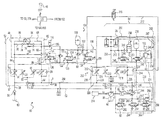
- FIG. 2 is a schematic illustration of an exemplary disclosed implement system that may be used in conjunction with the machine of FIG. 1 ;
- FIGS. 3-5 are schematic illustrations of optional exemplary disclosed valve arrangements that may be used in conjunction with the implement system of FIG. 2 ;
- FIGS. 6 and 7 are flowcharts illustrating exemplary disclosed methods of engine control that may be performed by the implement system of FIG. 2 .
- FIG. 1 illustrates an exemplary machine 10 having multiple systems and components that cooperate to excavate and load material onto a nearby haul vehicle 12 .
- machine 10 is a hydraulic excavator. It is contemplated, however, that machine 10 could alternatively embody another excavation or material handling machine, such as a backhoe, a front shovel, a dragline excavator, a crane, or another similar machine.
- Machine 10 may include, among other things, an implement system 14 configured to move a work tool 16 between a dig location 18 within a trench or at a pile, and a dump location 20 , for example over haul vehicle 12 .
- Machine 10 may also include an operator station 22 for manual control of implement system 14 . It is contemplated that machine 10 may perform operations other than truck loading, if desired, such as craning, trenching, and material handling.
- Implement system 14 may include a linkage structure acted on by fluid actuators to move work tool 16 .
- implement system 14 may include a boom 24 that is vertically pivotal relative to a work surface 26 by a pair of adjacent, double-acting, hydraulic cylinders 28 (only one shown in FIG. 1 ).
- Implement system 14 may also include a stick 30 that is vertically pivotal about a horizontal pivot axis 32 relative to boom 24 by a single, double-acting, hydraulic cylinder 36 .
- Implement system 14 may further include a single, double-acting, hydraulic cylinder 38 that is operatively connected to work tool 16 to tilt work tool 16 vertically about a horizontal pivot axis 40 relative to stick 30 .
- Boom 24 may be pivotally connected to a frame 42 of machine 10 , while frame 42 may be pivotally connected to an undercarriage member 44 and swung about a vertical axis 46 by one or more swing motors 49 .
- Stick 30 may pivotally connect work tool 16 to boom 24 by way of pivot axes 32 and 40 . It is contemplated that a greater or lesser number of fluid actuators may be included within implement system 14 and connected in a manner other than described above, if desired.
- Work tool 16 may include any device used to perform a particular task such as, for example, a bucket, a fork arrangement, a blade, a shovel, a crusher, a shear, a grapple, a grapple bucket, a magnet, or any other task-performing device known in the art.
- work tool 16 may alternatively or additionally rotate, slide, extend, open and close, or move in another manner known in the art.
- Operator station 22 may be configured to receive input from a machine operator indicative of a desired work tool movement.
- operator station 22 may include one or more input devices 48 embodied, for example, as single or multi-axis joysticks located proximal an operator seat (not shown).
- Input devices 48 may be proportional-type controllers configured to position and/or orient work tool 16 by producing a work tool position signal that is indicative of a desired work tool speed and/or force in a particular direction.
- the position signal may be used to actuate any one or more of hydraulic cylinders 28 , 36 , 38 and/or swing motor(s) 49 .
- different input devices may alternatively or additionally be included within operator station 22 such as, for example, wheels, knobs, push-pull devices, switches, pedals, and other operator input devices known in the art.
- machine 10 may include a hydraulic circuit 50 having a plurality of fluid components that cooperate to move implement system 14 (referring to FIG. 1 ).
- hydraulic circuit 50 may include a swing circuit 52 associated with swing motor 49 , a boom circuit 54 associated with hydraulic cylinders 28 , and at least one other circuit 55 associated with hydraulic cylinders 36 and 38 .
- Swing circuit 52 may include, among other things, a swing control valve 56 connected to regulate a flow of pressurized fluid from a pump 58 to swing motor(s) 49 and from swing motor(s) 49 to a low-pressure tank 60 .
- This fluid regulation may function to cause a swinging movement of work tool 16 about axis 46 (referring to FIG. 1 ) in accordance with an operator request received via input device 48 .
- a swing control valve 56 connected to regulate a flow of pressurized fluid from a pump 58 to swing motor(s) 49 and from swing motor(s) 49 to a low-pressure tank 60 .
- This fluid regulation may function to cause a swinging movement of work tool 16 about axis 46 (referring to FIG. 1 ) in accordance with an operator request received via input device 48 .
- any number of parallel swing motors 49 may be utilized.
- Each swing motor 49 may include a housing 62 at least partially forming a first and a second chamber (not shown) located to either side of an impeller 64 .
- first chamber is connected to an output of pump 58 (e.g., via a first chamber passage 66 formed within housing 62 ) and the second chamber is connected to tank 60 (e.g., via a second chamber passage 68 formed within housing 62 )
- impeller 64 may be driven to rotate in a first direction (shown in FIG. 2 ).
- impeller 64 may be driven to rotate in an opposite direction (not shown).
- the flow rate of fluid through impeller 64 may relate to a rotational speed of swing motor 49
- a pressure differential across impeller 64 may relate to an output torque thereof.
- Swing motor 49 may include built-in makeup functionality.
- a makeup passage 70 may be formed within housing 62 , between first chamber passage 66 and second chamber passage 68 , and a pair of opposing check valves 74 may be disposed within makeup passage 70 .
- a low-pressure passage 78 may be connected to makeup passage 70 at a location between check valves 74 . Based on a pressure differential between low-pressure passage 78 and first and second chamber passages 66 , 68 , one of check valves 74 may open to allow fluid from low-pressure passage 78 into the lower-pressure one of the first and second chambers. A significant pressure differential may generally exist between the first and second chambers during a swinging movement of implement system 14 .
- Pump 58 may be driven by an engine 59 of machine 10 to draw fluid from tank 60 via an inlet passage 80 , pressurize the fluid to a desired level, and discharge the fluid into swing circuit 52 via a common discharge or supply passage 82 .
- a check valve 83 may be disposed within discharge passage 82 , if desired, to provide for a unidirectional flow of pressurized fluid from pump 58 into swing circuit 52 .
- Pump 58 may embody, for example, a variable displacement pump (shown in FIG. 2 ), a fixed displacement pump, or another source known in the art. Pump 58 may be drivably connected to engine 59 or to another power source of machine 10 by, for example, a countershaft 71 , a belt, or in another suitable manner.
- pump 58 may be indirectly connected to engine 59 of machine 10 via a torque converter, a reduction gear box, an electrical circuit, or in any other suitable manner.
- Pump 58 may produce a stream of pressurized fluid having a pressure level and/or a flow rate determined, at least in part, by demands of the actuator(s) within swing circuit 52 that correspond with operator requested movements.
- Discharge passage 82 may be connected within swing circuit 52 to first and second chamber passages 66 , 68 via swing control valve 56 and first and second chamber conduits 84 , 86 , respectively, which extend between swing control valve 56 and swing motor 49 .
- Tank 60 may constitute a reservoir configured to hold a low-pressure supply of fluid.
- the fluid may include, for example, a dedicated hydraulic oil, an engine lubrication oil, a transmission lubrication oil, or any other fluid known in the art.
- One or more hydraulic circuits within machine 10 may draw fluid from and return fluid to tank 60 . It is contemplated that hydraulic circuit 50 may be connected to multiple separate fluid tanks (shown in FIG. 2 ) or to a single tank, as desired.
- Tank 60 may be fluidly connected to swing control valve 56 via a return passage 88 , and to first and second chamber passages 66 , 68 via swing control valve 56 and first and second chamber conduits 84 , 86 , respectively.
- One or more check valves 90 may be disposed within return passage 88 , if desired, to promote a unidirectional flow of fluid into tank 60 and/or to maintain a desired return flow pressure.
- Swing control valve 56 may have elements that are movable to control the rotation of swing motor 49 and corresponding swinging motion of implement system 14 .
- swing control valve 56 may include a first chamber supply element 92 , a first chamber drain element 94 , a second chamber supply element 96 , and a second chamber drain element 98 all disposed within a common block or housing 97 .
- the first and second chamber supply elements 92 , 96 may be connected in parallel to discharge passage 82 to regulate filling of their respective chambers with fluid from pump 58
- the first and second chamber drain elements 94 , 98 may be connected in parallel to return passage 88 to regulate draining of the respective chambers of fluid.
- a makeup valve 99 for example a check valve, may be disposed between discharge passage 82 and an outlet of first chamber drain element 94 and between discharge passage 82 and an outlet of second chamber drain element 98 .
- first chamber supply element 92 may be shifted to allow pressurized fluid from pump 58 to enter the first chamber of swing motor 49 via discharge passage 82 and first chamber conduit 84
- second chamber drain element 98 may be shifted to allow fluid from the second chamber of swing motor 49 to drain to tank 60 via second chamber conduit 86 and return passage 88
- second chamber supply element 96 may be shifted to communicate the second chamber of swing motor 49 with pressurized fluid from pump 58
- first chamber drain element 94 may be shifted to allow draining of fluid from the first chamber of swing motor 49 to tank 60 .
- both the supply and drain functions of swing control valve 56 may alternatively be performed by a single valve element associated with the first chamber and a single valve element associated with the second chamber, or by a single valve element associated with both the first and second chambers, if desired.
- Supply and drain elements 92 - 98 of swing control valve 56 may be solenoid-movable against a spring bias in response to a flow rate and/or position command issued by a controller 100 .
- swing motor 49 may rotate at a velocity that corresponds with the flow rate of fluid into and out of the first and second chambers. Accordingly, to achieve an operator-desired swing speed, a command based on an assumed or measured pressure drop may be sent to the solenoids (not shown) of supply and drain elements 92 - 98 that causes them to open an amount corresponding to the necessary rate of fluid flow into and out of swing motor 49 .
- This command may be in the form of a flow rate command or a valve element position command that is issued by controller 100 . It is contemplated that one or more of valves 92 - 98 could alternatively be pilot operated and/or pilot assisted, if desired.
- Swing circuit 52 may be fitted with an energy recovery module (ERM) 104 that is configured to selectively extract and recover energy from waste fluid that is discharged by swing motor 49 .
- ERM 104 may include, among other things, a recovery valve block (RVB) 106 that is fluidly connectable to swing motor 49 , a swing accumulator 108 configured to selectively communicate with swing motor 49 via RVB 106 , and a makeup accumulator 110 also configured to selectively and directly communicate with swing motor 49 .
- RVB 106 may be fixedly and mechanically connectable to one or both of swing control valve 56 and swing motor 49 , for example directly to housing 62 and/or directly to housing 97 .
- RVB 106 may include an internal first passage 112 fluidly connectable to first chamber conduit 84 , and an internal second passage 114 fluidly connectable to second chamber conduit 86 .
- Swing accumulator 108 may be fluidly connected to RVB 106 via a conduit 116
- makeup accumulator 110 may be fluidly connectable to low-pressure passage 78 in parallel with tank 60 (see connection A), via a conduit 118 .
- RVB 106 may house a selector valve 120 , a charge valve 122 associated with swing accumulator 108 , a discharge valve 124 associated with swing accumulator 108 and disposed in parallel with charge valve 122 , and a relief valve 76 .
- Selector valve 120 may automatically fluidly communicate one of first and second passages 112 , 114 with charge and discharge valves 122 , 124 based on a pressure of first and second passages 112 , 114 .
- Charge and discharge valves 122 , 124 may be selectively movable in response to commands from controller 100 to fluidly communicate swing accumulator 108 with selector valve 120 for fluid charging or discharging purposes.
- Relief valve 76 may be selectively connected to an outlet of swing accumulator 108 and/or a downstream side of charge valve 122 with tank 60 to relieve pressures of hydraulic circuit 50 .
- Selector valve 120 may be a pilot-operated, 2-position, 3-way valve that is automatically movable in response to fluid pressures in first and second passages 112 , 114 (i.e., in response to a fluid pressures within the first and second chambers of swing motor 49 ).
- selector valve 120 may include a valve element 126 that is movable from a first position (shown in FIG. 2 ) at which first passage 112 is fluidly connected to charge and discharge valves 122 , 124 via an internal passage 128 , toward a second position (not shown) at which second passage 114 is fluid connected to charge and discharge valves 122 , 124 via passage 128 .
- first passage 112 When first passage 112 is fluidly connected to charge and discharge valves 122 , 124 via passage 128 , fluid flow through second passage 114 may be inhibited by selector valve 120 , and vice versa.
- First and second pilot passages 130 , 132 may communicate fluid from first and second passages 112 , 114 to opposing ends of valve element 126 such that a higher-pressure one of first or second passages 112 , 114 may cause valve element 126 to move and fluidly connect the corresponding passage with charge and discharge valves 122 , 124 via passage 128 .
- Charge valve 122 may be a solenoid-operated, variable position, 2-way valve that is movable in response to a command from controller 100 to allow fluid from passage 128 to enter swing accumulator 108 .
- charge valve 122 may include a valve element 134 that is movable from a first position (shown in FIG. 2 ) at which fluid flow from passage 128 into swing accumulator 108 is inhibited, toward a second position (not shown) at which passage 128 is fluidly connected to swing accumulator 108 .
- valve element 134 When valve element 134 is away from the first position (i.e., in the second position or in an intermediate position between the first and second positions) and a fluid pressure within passage 128 exceeds a fluid pressure within swing accumulator 108 , fluid from passage 128 may fill (i.e., charge) swing accumulator 108 .
- Valve element 134 may be spring-biased toward the first position and movable in response to a command from controller 100 to any position between the first and second positions to thereby vary a flow rate of fluid from passage 128 into swing accumulator 108 .
- a check valve 136 may be disposed between charge valve 122 and swing accumulator 108 to provide for a unidirectional flow of fluid into swing accumulator 108 via charge valve 122 .
- Discharge valve 124 may be substantially identical to charge valve 122 in composition, and selectively movable in response to a command from controller 100 to allow fluid from swing accumulator 108 to enter passage 128 (i.e., to discharge).
- discharge valve 124 may include a valve element 138 that is movable from a first position (shown in FIG. 2 ) at which fluid flow from swing accumulator 108 into passage 128 is inhibited, toward a second position (not shown) at which swing accumulator 108 is fluidly connected to passage 128 .
- valve element 138 When valve element 138 is away from the first position (i.e., in the second position or in an intermediate position between the first and second positions) and a fluid pressure within swing accumulator 108 exceeds a fluid pressure within passage 128 , fluid from swing accumulator 108 may flow into passage 128 .
- Valve element 138 may be spring-biased toward the first position and movable in response to a command from controller 100 to any position between the first and second positions to thereby vary a flow rate of fluid from swing accumulator 108 into passage 128 .
- a check valve 140 may be disposed between swing accumulator 108 and discharge valve 124 to provide for a unidirectional flow of fluid from swing accumulator 108 into passage 128 via discharge valve 124 .
- a pressure sensor 102 may be associated with swing accumulator 108 and configured to generate signals indicative of a pressure of fluid within swing accumulator 108 , if desired.
- pressure sensor 102 may be disposed between swing accumulator 108 and discharge valve 124 . It is contemplated, however, that pressure sensor 102 may alternatively be disposed between swing accumulator 108 and charge valve 122 or directly connected to swing accumulator 108 , if desired. Signals from pressure sensor 102 may be directed to controller 100 for use in regulating operation of charge and/or discharge valves 122 , 124 .
- Swing and makeup accumulators 108 , 110 may each embody pressure vessels filled with a compressible gas that are configured to store pressurized fluid for future use by swing motor 49 .
- the compressible gas may include, for example, nitrogen, argon, helium, or another appropriate compressible gas.
- swing and makeup accumulators 108 , 110 may alternatively embody membrane/spring-biased or bladder types of accumulators, if desired.
- swing accumulator 108 may be a larger (i.e., about 5-20 times larger) and higher-pressure (i.e., about 5-60 times higher-pressure) accumulator, as compared to makeup accumulator 110 .
- swing accumulator 108 may be configured to accumulate fluid having a pressure in a range of about 300 bar
- makeup accumulator 110 may be configured to accumulate about 20-25% as much fluid as swing accumulator 108 having a pressure in a range of about 5-30 bar.
- swing accumulator 108 may be used primarily to assist the motion of swing motor 49 and to improve machine efficiencies
- makeup accumulator 110 may be used primarily as a makeup accumulator to help reduce a likelihood of voiding at swing motor 49 . It is contemplated, however, that other volumes and/or pressures may be accommodated by swing and makeup accumulators 108 , 110 , if desired.
- Controller 100 may be configured to selectively cause swing accumulator 108 to charge and discharge, thereby improving performance of machine 10 .
- a typical swinging motion of implement system 14 instituted by swing motor 49 may consist of segments of time during which swing motor 49 is accelerating a swinging movement of implement system 14 , and segments of time during which swing motor 49 is decelerating the swinging movement of implement system 14 .
- the acceleration segments may require significant energy from swing motor 49 that is conventionally realized by way of pressurized fluid supplied to swing motor 49 by pump 58 , while the deceleration segments may produce significant energy in the form of pressurized fluid that is conventionally wasted through discharge to tank 60 .
- Both the acceleration and deceleration segments may require swing motor 49 to convert significant amounts of hydraulic energy to swing kinetic energy, and vice versa.
- the pressurized fluid passing through swing motor 49 during deceleration still contains a large amount of energy. If the fluid passing through swing motor 49 is selectively collected within swing accumulator 108 during the deceleration segments, this energy can then be returned to (i.e., discharged) and reused by swing motor 49 during the ensuing acceleration segments.
- Swing motor 49 can be assisted during the acceleration segments by selectively causing swing accumulator 108 to discharge pressurized fluid into the higher-pressure chamber of swing motor 49 (via discharge valve 124 , passage 128 , selector valve 120 , and the appropriate one of first and second chamber conduits 84 , 86 ), alone or together with high-pressure fluid from pump 58 , thereby propelling swing motor 49 at the same or greater rate with less pump power than otherwise possible via pump 58 alone.
- Swing motor 49 can be assisted during the deceleration segments by selectively causing swing accumulator 108 to Charge with fluid exiting swing motor 49 , thereby providing additional resistance to the motion of swing motor 49 and lowering a restriction and associated cooling requirement of the fluid exiting swing motor 49 .
- Controller 100 may be in communication with the different components of swing circuit 52 to regulate operations of machine 10 .
- controller 100 may be in communication with the elements of swing control valve 56 in swing circuit 52 .
- controller 100 may be configured to selectively activate swing control valve 56 in a coordinated manner to efficiently carry out operator requested movements of implement system 14 .
- Controller 100 may include a memory, a secondary storage device, a clock, and one or more processors that cooperate to accomplish a task consistent with the present disclosure. Numerous commercially available microprocessors can be configured to perform the functions of controller 100 . It should be appreciated that controller 100 could readily embody a general machine controller capable of controlling numerous other functions of machine 10 . Various known circuits may be associated with controller 100 , including signal-conditioning circuitry, communication circuitry, and other appropriate circuitry. It should also be appreciated that controller 100 may include one or more of an application-specific integrated circuit (ASIC), a field-programmable gate array (FPGA), a computer system, and a logic circuit configured to allow controller 100 to function in accordance with the present disclosure.
- ASIC application-specific integrated circuit
- FPGA field-programmable gate array
- the operational parameters monitored by controller 100 may include a pressure of fluid within swing and/or boom circuits 52 , 54 .
- one or more pressure sensors 102 may be strategically located within first chamber and/or second chamber conduits 84 , 86 to sense a pressure of the respective passages and generate a corresponding signal indicative of the pressure directed to controller 100 . It is contemplated that any number of pressure sensors 102 may be placed in any location within swing and/or boom circuits 52 , 54 , as desired. It is further contemplated that other operational parameters such as, for example, speeds, temperatures, viscosities, densities, etc. may also or alternatively be monitored and used to regulate operation of hydraulic circuit 50 , if desired.
- Boom circuit 54 may include, among other things, a boom control valve 202 modulated by controller 100 to regulate a flow of pressurized fluid from pump 58 to hydraulic cylinders 28 and from hydraulic cylinders 28 to tank 60 .
- This fluid regulation may function to cause a lifting or lowering movement of work tool 16 about the associated horizontal axis (referring to FIG. 1 ) in accordance with an operator request received via input device 48 .
- Hydraulic cylinders 28 may each embody a linear actuator having a tubular housing and a piston assembly arranged to form two separated pressure chambers (e.g., a head chamber and a rod chamber) within the housing.
- the pressure chambers may be selectively supplied with pressurized fluid and drained of the pressurized fluid to cause the piston assembly to displace within the tubular housing, thereby changing an effective length of hydraulic cylinders 28 .
- the flow rate of fluid into and out of the pressure chambers may relate to a velocity of hydraulic cylinders 28 , while a pressure differential between the two pressure chambers may relate to a force imparted by hydraulic cylinders 28 on the associated linkage members.
- the expansion and retraction of hydraulic cylinders 28 may function to lift and lower work tool 16 relative to work surface 26 .
- Boom control valve 202 may be connected to hydraulic cylinders 28 by way of a head-end passage 206 and a rod-end passage 208 . Based on an operating position of boom control valve 202 , one of head- and rod-end passages 206 , 208 may be connected to pump 58 via boom control valve 202 , while the other of head- and rod-end passages 206 , 208 may be simultaneously connected to tank 60 via boom control valve 202 , thereby creating the pressure differential across the piston assembly within hydraulic cylinders 28 that causes extension or retraction thereof.
- a significant pressure differential may generally exist between the head and rod chambers during a lifting or lower movement of work tool 16 , particularly during a lowering movement when work tool 16 is heavily loaded. That is, during the lowering movement, head-end passage 206 may carry fluid having a much higher pressure than fluid carried within rod-end passage 208 at that same time.
- Pump 58 may produce a stream of pressurized fluid having a pressure level and/or a flow rate determined, at least in part, by demands of the actuators within boom circuit 54 that correspond with operator requested movements.
- a check valve 216 may be disposed within discharge passage 82 , between pump 58 and boom control valve 202 , if desired, to provide for a unidirectional flow of pressurized fluid from pump 58 into boom circuit 54 .
- Discharge passage 82 may be connected within boom circuit 54 to head- and rod-end passages 206 , 208 via boom control valve 202 .
- Boom control valve 202 in the disclosed exemplary embodiment, may be substantially identical to swing control valve 56 .
- boom control valve 202 may have elements that are movable to control the extension and retraction of hydraulic cylinders 28 and corresponding lifting and lowering motions of implement system 14 .
- boom control valve 202 may include a head-end supply element 218 , a head-end drain element 220 , a rod-end supply element 222 , and a rod-end drain element 224 all disposed within a common block or housing 226 .
- Head- and rod-end supply elements 218 , 222 may be connected in parallel to discharge passage 82 to regulate filling of their respective chambers with fluid from pump 58
- head- and rod-end drain elements 220 , 224 may be connected in parallel to a return passage 228 to regulate draining of the respective chambers of fluid to tank 60
- a makeup valve 230 for example a check valve, may be disposed between return passage 228 and an outlet of head-end drain element 220 and between return passage 228 and an outlet of rod-end drain element 224 .
- head-end supply element 218 may be shifted to allow pressurized fluid from pump 58 to enter the head chamber of hydraulic cylinders 28 via discharge passage 82 and head-end passage 206
- rod-end drain element 224 may be shifted to allow fluid from the rod chamber to drain into tank 60 via rod-end passage 208 and return passage 228
- rod-end supply element 222 may be shifted to communicate the rod chamber with pressurized fluid from pump 58
- head-end drain element 220 may be shifted to allow draining of fluid from the head chamber into tank 60 .
- both the supply and drain functions of boom control valve 202 may alternatively be performed by a single valve element associated with the head chamber and a single valve element associated with the rod chamber, or by a single valve element associated with both the head and rod chambers, if desired.
- Supply and drain elements 218 - 224 of boom control valve 202 may be solenoid-movable against a spring bias in response to a flow rate and/or position command issued by a controller 100 .
- hydraulic cylinders 28 may extend and retract at velocities that correspond with the flow rates of fluid into and out of the head and rod chambers.
- a command based on an assumed or measured pressure drop may be sent to the solenoids (not shown) of supply and drain elements 218 - 224 that causes them to open an amount corresponding to the necessary fluid flow rates at hydraulic cylinders 28 .
- This command may be in the form of a flow rate command or a valve element position command that is issued by controller 100 . It is contemplated that one or more of valves 218 - 224 could alternatively be pilot operated and/or pilot assisted, if desired.
- a pressure compensator 232 may be included within boom circuit 54 and associated with boom control valve 202 .
- pressure compensator 232 is disposed within discharge passage 82 at a location upstream of boom control valve 202 . In this location, pressure compensator 232 may be configured to supply a substantially constant flow rate of fluid to boom control valve 202 during fluctuations in supply pressure caused by interaction of boom circuit 54 with swing circuit 52 and/or circuit 55 .
- boom circuit 54 may also be fitted with an energy recovery module (ERM) 234 that is configured to selectively extract and recover enemy from waste fluid that is discharged by hydraulic cylinders 28 .
- ERM 234 may include, among other things, a boom accumulator 236 configured to selectively communicate with hydraulic cylinders 28 via a first charge valve 238 and a second charge valve 240 , and a motor 241 selectively driven by the accumulated fluid.
- a passage 242 may extend from head-end passage 206 through charge valve 238 to boom accumulator 236
- a passage 244 may extend from return passage 228 through charge valve 240 to boom accumulator 236 (and between accumulator 236 and an inlet of motor 241 ).
- One or more check valves 246 may be disposed within passages 242 and/or 244 to promote unidirectional fluid flows into boom accumulator 236 and or out of return passage 228 , respectively.
- First and second charge valves 238 , 240 may be selectively movable in response to commands from controller 100 to fluidly communicate head-end passage 206 and/or return passage 228 with boom accumulator 236 for fluid charging purposes.
- second charge valve 240 may be selectively movable to fluidly communicate boom accumulator 236 with the inlet of motor 241 for discharging purposes.
- Boom accumulator 236 of boom circuit 54 may be similar to swing and makeup accumulators 108 , 110 of swing circuit 52 .
- boom accumulator 236 may embody a pressure vessel filled with a compressible gas that is configured to store pressurized fluid for future use by hydraulic cylinders 28 .
- the compressible gas may include, for example, nitrogen, argon, helium, or another appropriate compressible gas.
- the fluid may flow into boom accumulator 236 . Because the gas therein is compressible, it may act like a spring and compress as the fluid flows into boom accumulator 236 .
- boom accumulator 236 may alternatively embody a membrane/spring-biased or bladder type of accumulator, if desired.
- boom accumulator 236 may be about the same size as or smaller than swing accumulator 108 , but configured to hold fluid at a lower pressure.
- boom accumulator 236 may have a volume of about 50-100 L, and be configured to accommodate pressures of about 80-150 bar. It is contemplated, however, that other volumes and pressures may be accommodated by boom accumulator 236 , if desired.
- Each of first and second charge valves 238 , 240 may be a solenoid-operated, variable position, 2-way valve that is movable in response to a command from controller 100 to allow fluid to enter boom accumulator 236 from the respective passages and for fluid from boom accumulator 236 to enter motor 241 via passage 244 .
- each charge valve 238 , 240 may include a valve element that is movable from a first position (shown in FIG. 2 ) at which fluid flow is inhibited, toward a second position (not shown) at which fluid may freely enter and/or leave boom accumulator 236 substantially unrestricted by the valve element.
- valve element When the valve element is away from the first position (i.e., in the second position or in an intermediate position between the first and second positions) and a fluid pressure in the respective passages exceeds a fluid pressure within boom accumulator 236 , the fluid may move into and fill (i.e., charge) boom accumulator 236 .
- the valve element of charge valve 240 when the valve element of charge valve 240 is in the second or intermediate position and the pressure within boom accumulator 236 exceeds the pressure within passage 244 , the fluid may exit boom accumulator 236 and pass to motor 241 via passage 244 .
- the valve element may be spring-biased toward the first position and movable in response to a command from controller 100 to any position between the first and second positions to thereby vary a flow rate of fluid into boom accumulator 236 .
- a pressure relief arrangement 247 may be associated with boom accumulator 236 .
- Pressure relief arrangement 247 may include a pressure relief valve 248 disposed in parallel with a restriction 250 , both located between boom accumulator 236 and tank 60 .
- Pressure relief valve 248 may be normally closed, but selectively moved to a flow-passing position to relieve fluid pressures within boom accumulator 236 .
- Restriction 250 may be configured to continuously leak some fluid from boom accumulator 236 to tank 60 .
- An additional pressure sensor 102 may be associated with boom accumulator 236 , at a location between boom accumulator 236 and pressure relief arrangement 247 to generate corresponding pressure signals directed to controller 100 .
- a bypass arrangement 245 may extend between passages 242 and 244 .
- Bypass arrangement 245 may include a bypass control valve 249 disposed within a bypass passage 251 .
- Bypass control valve 249 may be a solenoid-operated, variable position, 2-way valve that is movable in response to a command from controller 100 to allow fluid from hydraulic cylinder 28 to selectively bypass accumulator 236 and flow directly to motor 241 .
- control valve 249 may include a valve element that is movable from a first position (shown in FIG. 2 ) at which fluid flow through the respective valve is inhibited, toward a second position (not shown) at which fluid may freely flow substantially unrestricted from passage 242 to 244 without ever entering or exiting accumulator 236 .
- the valve element may be spring-biased toward the first position, and movable in response to a command from controller 100 to any position between the first and second positions to thereby vary a flow rate of fluid through bypass passage 251 . It may be desirable to bypass accumulator 236 , for example, when accumulator 236 is already full of pressurized fluid, the fluid being discharged from hydraulic cylinders 28 is less than a pressure of accumulator 236 yet still high enough to drive motor 241 , and/or there is an immediate need for power at motor 241 and accumulator 236 has an insufficient supply of accumulated fluid.
- Motor 241 may function to convert energy stored in the form of pressurized fluid in boom accumulator 236 (and/or energy in the form of pressurized fluid discharged from hydraulic cylinders 28 via bypass passage 251 ) to mechanical energy.
- motor 241 may be fluidly connected in parallel to both return passage 228 (downstream of check valve 246 ) and to boom accumulator 236 via passage 244 and charge valve 240 . In this configuration, fluid from either passage may be directed through motor 241 and thereby used to drive motor 241 .
- Motor 241 in the depicted example, is a variable displacement hydraulic motor that is mechanically coupled to engine 59 , to an input shaft of pump 58 , and/or to another rotary device.
- motor 241 when driven by pressurized fluid, may mechanically assist engine 59 (e.g., to add power to an already rotating output of engine 59 or to assist in starting engine 59 ), pump 58 , and/or the other rotary device.
- Motor 241 may assist pump 58 and engine 59 when pump 58 has a positive displacement or, alternatively assist only engine 59 when pump 58 has a neutral displacement.
- engine 59 may selectively drive motor 241 to increase a pressure of the fluid directed through motor 241 and recirculated back to hydraulic cylinders 28 .
- One or more motor control valves may be associated with an outlet of motor 241 and used to regulate operation of motor 241 .
- three different control valves are shown, including a tank control valve 252 , a rod-end control valve 254 , and a head-end control valve 256 all connected in parallel to the outlet of motor 241 .
- Tank control valve 252 may be situated between motor 241 and tank 60 , within a drain passage 258 .
- Rod-end control valve 254 may be situated between motor 241 and rod-end passage 208 , within a rod-end return passage 260 .
- Head-end control valve 256 may be situated between motor 241 and head-end passage 206 (e.g., via passage 242 ), within a head-end return passage 262 .
- One or more check valve 264 may be associated with one or more of passages 258 - 262 to help ensure unidirectional flows within these passages.
- Each of control valves 252 - 256 may be a solenoid-operated, variable position, 2-way valve that is movable in response to a command from controller 100 to allow fluid from motor 241 to enter tank 60 , the head-end of hydraulic cylinders 28 , or the rod-end of hydraulic cylinders 28 , thereby accomplishing different purposes.
- each control valve 252 - 256 may include a valve element that is movable from a first position (shown in FIG. 2 ) at which fluid flow through the respective valve is inhibited, toward a second position (not shown) at which fluid may freely flow unrestricted by the corresponding valve element.
- valve element may be spring-biased toward the first position, and movable in response to a command from controller 100 to any position between the first and second positions to thereby vary a flow rate and/or pressure of fluid through the respective valve. It is contemplated that one or more of valves 252 - 256 could alternatively be pilot operated and/or pilot assisted, if desired.
- control valves 252 - 256 may be independently and/or simultaneously operable (i.e., moved to the second or an intermediate position) to accomplish different purposes. For example, to extract a maximum amount of energy from the fluid passing through motor 241 (e.g., during an engine starting event), a maximum pressure drop should be generated across motor 241 . This maximum pressure drop may occur when the pressure downstream of motor 241 is lowest. In most situations, the maximum pressure drop may occur when only tank control valve 252 is used, and the corresponding element moved completely to the second position. In some situations, however, a greater pressure drop may be generated by using one of rod- and head-end control valves 254 , 256 alone or together with tank control valve 252 .
- the fluid passing through motor 241 may be directed back to hydraulic cylinders 28 .
- This may accomplish several purposes. For example, energy associated with the fluid passing through motor 241 may first be recovered and used to drive engine 59 and/or pump 58 , thereby improving an efficiency of machine 10 .
- the fluid may be used for internal regeneration within hydraulic cylinders 28 that helps to reduce voiding. The energy removed by motor 241 prior to fluid recirculation back to hydraulic cylinders 28 may not be needed within hydraulic cylinders 28 during an overrunning condition, as the returning fluid may only be used in this situation to inhibit voiding and not used to move hydraulic cylinders 28 .
- pump 58 may not be required to expend as much energy to provide fluid to hydraulic cylinders 28 during the overrunning condition.
- motor 241 may be capable of further increasing the pressure of the fluid being redirected back to hydraulic cylinders 28 during a non-overrunning condition, when motor 241 is being driven by engine 59 .
- an additional pressure relief valve 266 may be associated with the outlet of motor 241 .
- Pressure relief valve 266 may be disposed between motor 241 and return passage 228 .
- Pressure relief valve 266 may normally be closed, but selectively moved to a flow-passing position to relieve fluid pressures downstream of motor 241 (e.g., when motor 241 increases a pressure of the fluid passing therethrough).
- An additional pressure sensor 102 may be associated with motor 241 , and positioned at a location between motor 241 and pressure relief valve 266 to generate corresponding pressure signals directed to controller 100 . Based on these pressure signals, controller 100 may be able to properly control operation of valves 252 - 256 .
- Swing and boom circuits 52 , 54 may be interconnected for flow sharing, energy recuperation, and/or engine starting purposes.
- a common return passage 268 may extend between swing and boom circuits 52 , 54 .
- Common return passage 268 may connect return passage 88 from swing circuit 52 with return passage 228 from boom circuit 54 .
- makeup accumulator 110 may be filled with fluid from both circuits 52 , 54 and, likewise, makeup accumulator 110 may provide fluid to both circuits 52 , 54 and to motor 241 via check valve 246 .
- a common accumulator passage 272 may extend from swing accumulator 108 of swing circuit 52 to connect with passage 244 of boom circuit 54 , and a control valve 270 may be disposed within passage 272 to regulate flows of fluid between circuits 52 , 54 .
- pressurized fluid from swing accumulator 108 may be passed to boom accumulator 236 via common accumulator passage 272 , valve 270 , passage 244 , and second charge valve 240 , and vice versa.
- pressurized fluid from swing accumulator 108 may be passed through and converted to mechanical energy by motor 241 via common accumulator passage 272 , valve 270 , and passage 244 (e.g., during an engine starting event).
- valve 270 is a solenoid-operated valve that is pilot-assisted (e.g., internally pilot assisted with high pressure fluid from swing accumulator 108 ).
- an accumulator return passage may be included and used to connect an outlet of motor 241 with common accumulator passage 272 to direct high-pressure fluid exiting motor 241 into swing circuit 52 (e.g., into swing accumulator 108 ) and/or into boom circuit 54 (e.g., into boom accumulator 236 ).
- a control valve e.g., one of motor, head-end, rod-end control valves or another separate control valve
- Controller 100 may be configured to selectively cause boom accumulator 236 to charge and discharge, thereby improving performance of machine 10 .
- a motion of implement system 14 instituted by hydraulic cylinders 28 may consist of segments of time during which hydraulic cylinders 28 are lifting implement system 14 , and segments of time during which hydraulic cylinders are lowering implement system 14 .
- the lifting segments may require significant energy from hydraulic cylinders 28 that is conventionally realized by way of pressurized fluid supplied to hydraulic cylinders 28 by pump 58 , while the lowering segments may produce significant energy in the form of pressurized fluid that is conventionally wasted through discharge to tank 60 .
- Both the lifting and lowering segments may require hydraulic cylinders 28 to convert significant amounts of hydraulic energy to kinetic energy, and vice versa.
- the pressurized fluid passing through hydraulic cylinders 28 during lowering still contains a large amount of energy. If the fluid discharged from hydraulic cylinders 28 is selectively collected within boom accumulator 236 during the lowering segments, this energy can then be returned to (i.e., discharged) and reused by hydraulic cylinders 28 during the ensuing lifting segments.
- Pump 58 (and engine 59 ) can be assisted during the lifting segments by selectively causing boom accumulator 236 to discharge pressurized fluid through motor 241 (via second charge valve 240 and passage 244 ), thereby driving pump 58 at the same or greater rate with less engine power than otherwise possible.
- controller 100 may be configured to additionally or alternatively direct the fluid discharged from boom accumulator 236 during lowering of implement system 14 (or at any other time) into swing circuit 52 (e.g., into swing accumulator 108 ) to assist movements of swing motor 49 .
- controller 100 may be configured to additionally or alternatively direct fluid discharged from swing accumulator 108 into boom accumulator 236 and/or through motor 241 .
- controller 100 may additionally or alternatively direct fluid discharged from motor 241 into one or both of swing and boom accumulators 108 , 236 .
- Controller 100 may also be configured to implement a version of peak shaving in association with boom circuit 54 .
- controller 100 may be configured to cause boom accumulator 236 to charge with fluid exiting pump 58 (e.g., via control valve 202 , head-end passage 206 , passage 242 , check valve 246 , and first charge valve 238 ) when pump 58 and engine 59 have excess capacity (i.e., a capacity greater than required by boom circuit 54 to move work tool 16 as requested by the operator) during a lifting mode of operation.
- excess capacity i.e., a capacity greater than required by boom circuit 54 to move work tool 16 as requested by the operator
- the high-pressure fluid previously collected from pump 58 within boom accumulator 236 may be discharged through motor 241 in the manner described above to assist engine 59 and pump 58 .
- Controller 100 may further be configured to implement peak shaving in connection with both of swing and boom circuits 52 , 54 .
- excess fluid from pump 58 may be directed, by way of common accumulator passage 272 between circuits and stored within either of swing or boom accumulators 108 , 236 .
- an electric starting motor 274 may be used alone or in conjunction with motor 241 to start engine 59 .
- Starting motor 274 may be supplied with power from an onboard battery (not shown), regulated by controller 100 , and connected to engine 59 in any conventional manner.
- FIGS. 3-5 are simplified illustrations of hydraulic circuit 50 depicting different configurations that could be used to control this functionality.
- a control valve 400 may be used to selectively control flows of fluid from swing accumulator 108 to any one of hydraulic cylinders 28 , 36 , 38 and/or swing motor(s) 49 (“the actuators”) when engine 59 is shutdown and/or being started.
- the actuators any one of hydraulic cylinders 28 , 36 , 38 and/or swing motor(s) 49 (“the actuators”) when engine 59 is shutdown and/or being started.
- pressurized fluid from swing accumulator 108 may be provided to the corresponding circuits ( 52 , 54 , 55 ) of the particular actuators via control valve 400 (e.g., by way of discharge passage 82 ).
- fluid directed to the actuators may come from pump 58 alone, from swing accumulator 108 alone, or from a combination of the different sources.
- the required fluid may be provided by pump 58 alone.
- High-pressure fluid from pump 58 may be selectively used to charge swing accumulator 108 via valve 400 any time pump 58 has excess capacity.
- Fluid being discharged from swing motor 49 may likewise be directed into swing accumulator 108 (e.g., via valve 134 ), as long as the fluid has a sufficiently high pressure. Otherwise, the fluid discharged from the swing motor 49 may be directed to tank 60 via valve 56 and passage 88 or via passage 268 , motor 241 (referring to FIG. 2 ), and valve 252 .
- FIG. 4 illustrates another embodiment, in which accumulated fluid can be used to power any one of hydraulic cylinders 28 , 36 , 38 and/or swing motor(s) 49 (“the actuators”) when engine 59 is shutdown and/or being started (i.e., when pump 58 is not pressurizing fluid or pressurizing too little fluid).
- hydraulic circuit 50 includes an additional accumulator (e.g., a startup accumulator) 402 that supplies previously collected high-pressure fluid through control valve 400 to discharge passage 82 .
- Accumulator 402 may have a size and/or a pressure larger than swing and boom accumulators 108 , 236 .
- accumulator 402 may be configured to collect 35 L or more of fluid having a pressure of about 350 bar or higher.
- the fluid collected within accumulator 402 may come from any combination of different sources.
- the fluid may be directed from swing circuit 52 (e.g., from motor 49 and/or swing accumulator 108 ) through a valve 404 into accumulator 402 .
- the fluid may be directed into accumulator 402 from discharge passage 82 (i.e., from pump 58 ) via a valve 406 , and/or from motor 241 via a valve 408 .
- the fluid may be directed into accumulator 402 from boom circuit 54 (e.g., from hydraulic cylinders 28 and/or boom accumulator 236 ) via a valve 410 .
- Intensifier 412 may essentially consist of a motor element coupled with a pump element, the motor element being driven by the pressurized fluid from boom circuit 54 to power the pump element and pressurize fluid from tank 60 to an even higher pressure.
- Valves 404 - 410 may be substantially identical, and include a proportional valve element that is solenoid operable against a spring bias to any position between a completely closed position and a completely open position.
- FIG. 5 illustrates yet another embodiment, in which fluid accumulated within boom circuit 54 can be used to power any one of hydraulic cylinders 28 , 36 , 38 and/or swing motor(s) 49 (“the actuators”) when engine 59 is shutdown and/or being started (i.e., when pump 58 is not pressurizing fluid or pressurizing too little fluid).
- hydraulic circuit 50 does not require additional accumulator 402 , but instead uses boom accumulator 236 (similar to the way that the embodiment of FIG. 3 utilizes swing accumulator 108 ).
- control valve 400 may be configured to receive fluid from boom accumulator 236 , and selectively direct the fluid through intensifier 412 and check valve 414 into discharge passage 82 .
- Control valve 400 from any of the embodiments of FIGS. 3-5 may take on any form known in the art.
- control valve 400 could embody a solenoid-operated proportional control valve movable to any position between a closed position and a fully open position. And the movement of control valve 400 may be controlled based on a desired flow rate of fluid into and/or out of the actuators, a measured pressure of accumulated fluid, and/or monitored operational conditions of pump 58 .
- control valve 400 could be a load-sense valve, wherein the flow rate of fluid may be regulated based on a pressure of the fluid passing through control valve 400 and a pressure of the fluid being discharged by pump 58 .
- control valve 400 may be pressure-compensated.
- control valve 400 could include a pressure compensating element that moves to help ensure that the flow rate of fluid passing through valve 400 (for a given opening area) remains substantially constant and reliable regardless of fluctuations in pressure.
- FIGS. 6 and 7 illustrate different methods of engine and hydraulic circuit control. FIGS. 6 and 7 will be described in more detail below to further illustrate the disclosed concepts.
- the disclosed hydraulic circuit may be applicable to any machine that performs a substantially repetitive work cycle, which involves swinging and/or lifting movements of a work tool.
- the disclosed hydraulic circuit may help to improve machine performance and efficiency by assisting movements of the work tool with accumulators during different segments of the work cycle.
- the disclosed hydraulic circuit may help to improve machine efficiency by capturing and reusing otherwise wasted energy in a number of different ways, including restarting the associated engine when shut down during idle periods. Control of hydraulic circuit 50 will now be described in detail.
- engine 59 may drive pump 58 to draw fluid from tank 60 and pressurize the fluid.
- the pressurized fluid may be directed, for example, into the head-end chambers of hydraulic cylinders 28 via head-end supply element 218 , while at the same time fluid may be allowed to flow out of the rod-end chambers of hydraulic cylinders 28 via rod-end drain element 224 .
- This operation may cause hydraulic cylinders 28 to extend and raise boom 24 .
- fluid previously collected within boom accumulator 236 may assist the raising of boom 24 .
- pressurized fluid from within boom accumulator 236 may be directed through charge valve 240 and passage 244 to motor 241 .
- This fluid may be further pressurized by motor 241 , and directed to the head-end chambers of hydraulic cylinders 28 via head-end control valve 256 and passage 262 .
- This fluid may supplement the supply of fluid from pump 58 or may be the sole source of fluid used to raise boom 24 , as desired.
- the fluid within boom accumulator 236 may be pressurized to some extent already, the energy required to further pressurize the fluid may be less than required by pump 58 to fully pressurize fluid drawn from tank 60 . Accordingly, a savings may be realized by using fluid from boom accumulator 236 to help raise boom 24 .
- the fluid being discharged from the rod-end chambers of hydraulic cylinders 28 may be selectively collected within boom accumulator 236 and/or used to drive motor 241 . That is, in some applications, the fluid being discharged from hydraulic cylinders 28 may have an elevated pressure. For example, when boom 24 is engaged with work surface 26 and a portion of frame 42 is raised away from work surface 26 , the weight of machine 10 may pressurize fluid being discharged from the rod-end chambers during raising of boom 24 (i.e., during lowering of frame 42 ).
- the pressurized fluid may be directed from rod-end drain element 224 through return passage 228 , past check valve 246 , and through motor 241 (i.e., to drive motor 241 ) or into passage 244 and boom accumulator 236 via charge valve 240 .
- motor 241 By driving motor 241 with the fluid, some energy contained within the fluid may be transferred to engine 59 and/or pump 58 , thereby improving the efficiency of machine 10 .
- Lowering of boom 24 may be achieved in similar manner.
- fluid pressurized by pump 58 may be directed into the rod-end chambers of hydraulic cylinders 28 via rod-end supply element 222 , while at the same time fluid may be allowed to flow out of the head-end chambers of hydraulic cylinders 28 via head-end drain element 220 . This operation may cause hydraulic cylinders 28 to retract and lower boom 24 .
- fluid previously collected within boom accumulator 236 may assist the lowering of boom 24 .
- pressurized fluid from within boom accumulator 236 may be directed through charge valve 240 and passage 244 to motor 241 .
- This fluid may be further pressurized by motor 241 (or alternatively energy may be absorbed from this fluid by motor 241 ), and then directed to the rod-end chambers of hydraulic cylinders 28 via rod-end control valve 254 and passage 260 .
- This fluid may supplement the supply of fluid from pump 58 or may be the sole source of fluid used to lower boom 24 , as desired. As described above, reducing the load on pump 58 may improve the efficiency of machine 10 .
- the fluid being discharged from the head-end chambers of hydraulic cylinders 28 may be selectively collected within boom accumulator 236 and/or used to drive motor 241 . That is, in some applications, the fluid being discharged from hydraulic cylinders 28 may have an elevated pressure.
- the weight of the material (and of boom 24 , stick 30 , and work tool 16 ) acting through boom 24 may pressurize fluid being discharged from the head-end chambers of hydraulic cylinders 28 during lowering of boom 24 .
- the pressurized fluid may be directed from the head-end chambers past check valve 246 and through charge valve 238 into boom accumulator 236 .
- the fluid being discharged from the head-end chambers may be directed through passage 242 , bypass control valve 249 , and passage 244 to motor 241 .
- This high-pressure fluid may then drive motor 241 to impart energy to engine 59 and/or pump 58 .
- FIG. 6 illustrates a control method used to selectively shut down and restart engine 59 , to improve efficiencies of machine 10 during idle periods of time.
- control may initiate after engine 59 is already operational (Step 300 ).
- Controller 100 may then check to see if the operator is inside machine 10 and actively operating machine 10 (Step 302 ).
- Controller 100 may determine that the operator is inside machine 10 and actively operating machine 10 based on any number of parameters known in the art. For example, the operator may be determined to be inside station 22 based on activation of a seatbelt sensor, a door sensor, or another similar sensor, and actively operating machine 10 based on detected movement of input device 48 . If the operator is inside machine 10 and actively operating machine 10 , control may return to step 300 .
- controller 100 may check to see if it is ok to shut down engine 59 (Step 304 ). In some situations, shutting down engine 59 could cause damage to engine 59 and/or other machine components, or present undesired situations. These situations may occur when engine 59 is operating at a speed above or below a desired range, when an exhaust treatment device of engine 59 is undergoing a regeneration event, when a temperature of engine 59 falls outside of a desired range, when a battery level is too low to restart engine 59 , etc. Controller 100 may determine if it is ok to shut down engine 59 by checking the status of these conditions.
- controller 100 may pause for a predetermined period of time (Step 306 ), and then perform the check again (Step 308 ) for redundancy purposes. In one embodiment, the pause may last for about 15 seconds. It is contemplated that steps 306 and 308 may be omitted, if desired.
- controller 100 may check to see if the operator has become active during completion of steps 304 - 308 (Step 310 ). If the operator has initiated movement of input device 48 during this time, control may return to step 300 . However, if at step 310 , controller 100 determines that the operator has remained inactive, controller 100 may check to see if swing accumulator 108 has accumulated sufficient fluid to hydraulically restart engine 59 (Step 312 ). In particular, based on a pressure of fluid within swing accumulator 108 , controller 100 may be able to determine (e.g., based on a map stored in memory) if a sufficient volume of fluid exists to restart engine 59 .
- controller 100 may be configured to primarily use swing accumulator 108 to restart engine 59 due to the higher pressure capacity of swing accumulator 108 .
- controller 100 may be configured to alternatively or additionally use makeup accumulator 110 , boom accumulator 236 , and/or accumulator 402 to restart engine 59 , if desired.
- controller 100 may cause swing accumulator 108 to be charged (Step 314 ).
- swing accumulator 108 may be charged in any number of different ways, including by directing pressurized fluid from pump 58 into swing accumulator 108 .
- Controller 100 may continue to check on the charge of swing accumulator 108 (Step 316 ), and then proceed to shut engine 59 down (Step 318 ) when sufficient charge has been detected.
- controller 100 may continuously monitor at least three different things. For example, controller 100 may monitor the operator to determine if the operator has become active (Step 322 ), monitor machine parameters to see if they have deviated from desired levels (Step 328 ), and check to see if the operator has left station 22 or if machine 10 is experiencing unexpected problems (Step 342 ). Engine 59 may remain off, at step 320 , as long as the operator remains inactive inside station 22 , the machine parameters are within threshold limits, and no problems with machine 10 have been detected.
- controller 100 may cause engine 59 to restart (Step 324 ) and thereafter confirm operational status of engine 59 (Step 326 ). Control may loop from step 324 through step 326 until controller 100 confirms that engine 59 has been restarted. Control may then return to step 300 .
- controller 100 may compare various machine parameters (e.g., battery levels, ambient temperatures, engine block temperatures, hydraulic pressures, etc.) to threshold levels, and selectively cause engine 59 to restart (Step 330 ) if any one or more of these parameters deviate from desired values. For example, if the battery of machine 10 nears a minimum voltage level required to restart engine 59 , controller 100 may cause engine 59 to restart and charge the battery. Similarly, if ambient and/or engine block temperatures fall to levels that may make restarting of engine 59 difficult, controller 100 may cause engine 59 to restart. Controller 100 may then confirm operational status of engine 59 (Step 332 ), and control may loop from step 330 through step 332 until controller 100 confirms that engine 59 has been restarted.
- various machine parameters e.g., battery levels, ambient temperatures, engine block temperatures, hydraulic pressures, etc.
- controller 100 may again check to see if the operator is active (Step 336 ) and if the machine parameters are within the desired range (Step 338 ). As long as the operator remains inactive and the machine parameters are outside the desired range, controller 100 may keep engine 59 running (control may loop from step 334 through steps 336 and 338 ). From step 336 , when controller 100 determines that the operator has become active, control may return to step 300 . And from step 338 , when the machine parameters return to within their desired range (and the operator is still inactive), engine 59 may be shut down again (Step 340 ), and control may return to step 320 .
- controller 100 may increment a counter and use the counter to determine if machine 10 is experiencing any problems. In particular, it may be possible for a problem with the battery of machine 10 , with an engine block temperature sensor, or with another component to occur and cause engine 59 to repeatedly shut down. In this situation, controller 100 may be able to detect the malfunction based on the cycle count, and selectively respond to inhibit further machine damage from occurring. Specifically, at step 342 , controller 100 may determine that further machine damage is possible (e.g., based on the count of shutdown events), and selectively shut all of machine 10 down (i.e., not just engine 59 ) (Step 344 ).
- controller 100 may be able to determine that further machine damage is possible in other ways, if desired. Controller 100 may also cause all of machine 10 to shut down at step 344 when the operator leaves station 22 . Once all of machine 10 has been shut down, controller 100 may only allow machine 10 to restart when the operator manually requests such a restart (e.g., by way of a key switch) (Step 346 ). Thereafter, controller 100 may follow a normal start routine (Step 348 ), and control may return to step 300 .
- engine 59 may be restarted using electric start motor 274 alone, motor 241 alone, or both motors 241 and 274 .
- engine restart may be initiated primarily using motor 241 so as to extend the life of electric start motor 274 and the associated circuitry.
- the flowchart of FIG. 7 illustrates one exemplary way of determining how to restart engine 59 .
- the method of FIG. 7 may initiate when engine 59 is off (Step 500 ) and a command to restart has been received (Step 502 ).
- the command to restart may come directly from the operator of machine 10 or, alternatively through completion of any number of different automated processes like that of FIG. 6 .
- controller 100 may determine if sufficient hydraulic power exists within any one or more of accumulators 108 , 110 , 236 , 402 to assist in starting engine 59 (Step 504 ). For example, controller 100 may reference an actual pressure of the fluid within swing accumulator 108 with a lookup map stored in memory to determine if a threshold amount of torque capacity exists.
- controller 100 may determine if the amount and pressure of the fluid within swing accumulator 108 , when directed through motor 241 , is enough to at least assist in starting engine 59 . If the pressure of the fluid in swing accumulator 108 is below the threshold level (e.g., about 75 kPa), controller 100 may energize electric start motor 274 to start engine 59 without any assistance (Step 506 ).
- the threshold level e.g., about 75 kPa
- controller 100 may determine if enough torque capacity exists to start engine 59 with motor 241 alone. Specifically, controller 100 may reference the pressure of the fluid within swing accumulator 108 with the lookup map to determine if the torque capacity of motor 241 , when fed with the accumulated fluid, is greater than a maximum torque capacity (Step 5508 ).
- controller 100 may cause motor 241 to hydraulically restart engine 59 alone (Step 510 ). Otherwise, controller 100 may cause motor 241 to hydraulically assist electric starting motor 274 in starting engine 59 (Step 512 ).
- the disclosed circuit may integrate swing and boom circuits during both energy recovery and reuse, a greater amount of energy may be stored and re-used.
- the disclosed system may utilize multiple different accumulators, the accumulators may be relatively small, inexpensive, and easy to package.
- the size and/or pressure capacity of each of the accumulators may be tailored to provide enhanced performance to each circuit it is connected to.
- the associated fluid may be stored, routed, pressure-enhanced, and/or converted in many different ways.
- the ability to internally regenerate fluid associated with hydraulic cylinders 28 in combination with energy recovery via motor 241 , even higher efficiencies may be realized.
- the ability to provide immediate actuator operation during engine shutdown and/or restart may enhance machine performance, and improve operator satisfaction by reducing perceived unresponsiveness of machine 10 .
Priority Applications (4)
| Application Number | Priority Date | Filing Date | Title |
|---|---|---|---|
| US14/263,710 US9618014B2 (en) | 2014-02-28 | 2014-04-28 | Implement system having hydraulic start assist |
| CN201580010314.2A CN106257991B (zh) | 2014-02-28 | 2015-02-18 | 具有液压启动辅助的机具系统 |
| DE112015000564.1T DE112015000564T5 (de) | 2014-02-28 | 2015-02-18 | Arbeitsaufsatzsystem mit Hydraulikstartunterstützung |
| PCT/US2015/016249 WO2015130518A1 (en) | 2014-02-28 | 2015-02-18 | Implement system having hydraulic start assist |
Applications Claiming Priority (2)
| Application Number | Priority Date | Filing Date | Title |
|---|---|---|---|
| US201461946452P | 2014-02-28 | 2014-02-28 | |
| US14/263,710 US9618014B2 (en) | 2014-02-28 | 2014-04-28 | Implement system having hydraulic start assist |
Publications (2)
| Publication Number | Publication Date |
|---|---|
| US20150247304A1 US20150247304A1 (en) | 2015-09-03 |
| US9618014B2 true US9618014B2 (en) | 2017-04-11 |
Family
ID=54006508
Family Applications (2)
| Application Number | Title | Priority Date | Filing Date |
|---|---|---|---|
| US14/263,680 Abandoned US20150247509A1 (en) | 2014-02-28 | 2014-04-28 | Machine having hydraulic start assist system |
| US14/263,710 Active 2035-01-21 US9618014B2 (en) | 2014-02-28 | 2014-04-28 | Implement system having hydraulic start assist |
Family Applications Before (1)
| Application Number | Title | Priority Date | Filing Date |
|---|---|---|---|
| US14/263,680 Abandoned US20150247509A1 (en) | 2014-02-28 | 2014-04-28 | Machine having hydraulic start assist system |
Country Status (4)
| Country | Link |
|---|---|
| US (2) | US20150247509A1 (zh) |
| CN (1) | CN106257991B (zh) |
| DE (1) | DE112015000564T5 (zh) |
| WO (2) | WO2015130518A1 (zh) |
Cited By (5)
| Publication number | Priority date | Publication date | Assignee | Title |
|---|---|---|---|---|
| US20160281745A1 (en) * | 2015-03-25 | 2016-09-29 | Caterpillar Inc. | Integration of Swing Energy Recovery and Engine Anti-Idling Systems |
| US20160319796A1 (en) * | 2013-12-20 | 2016-11-03 | Manitou Bf | Method for starting and stopping an internal combustion engine of an industrial truck |
| US20170204887A1 (en) * | 2014-10-06 | 2017-07-20 | Sumitomo Heavy Industries, Ltd. | Shovel |
| US10704615B2 (en) * | 2018-08-21 | 2020-07-07 | Ford Global Technologies, Llc | Vehicle and system for controlling a vehicle transmission |
| US11110788B2 (en) * | 2018-09-20 | 2021-09-07 | Robert Bosch Gmbh | Control structure for a mobile work machine, method, and work machine |
Families Citing this family (6)
| Publication number | Priority date | Publication date | Assignee | Title |
|---|---|---|---|---|
| JP6368553B2 (ja) * | 2014-06-06 | 2018-08-01 | Kyb株式会社 | 流体圧システム |
| US10422361B2 (en) | 2016-12-14 | 2019-09-24 | Cnh Industrial America Llc | Regenerative energy capturing and launching assistant |
| CN109958565B (zh) * | 2017-12-25 | 2021-03-30 | 中车沈阳机车车辆有限公司 | 发动机辅助起动装置及工程车 |
| CN108216191A (zh) * | 2017-12-29 | 2018-06-29 | 徐州重型机械有限公司 | 作业车辆发动机启闭控制方法、系统及作业车辆 |
| DE102018101924A1 (de) * | 2018-01-29 | 2019-08-01 | Liebherr-Hydraulikbagger Gmbh | Arbeitsmaschine mit Hydraulik zur Energierekuperation |
| CN111336138B (zh) * | 2020-03-26 | 2021-03-09 | 湖南机电职业技术学院 | 一种液压启停装置 |
Citations (26)
| Publication number | Priority date | Publication date | Assignee | Title |
|---|---|---|---|---|
| US4959962A (en) | 1987-08-27 | 1990-10-02 | Man Nutzfahrzeuge Gmbh | Starter system for automatically turning off and restarting a motor vehicle engine |
| US6431050B1 (en) * | 2000-06-26 | 2002-08-13 | Caterpillar Inc. | Apparatus for multiplexing a plurality of hydraulic cylinders |
| US6973781B2 (en) | 2003-10-29 | 2005-12-13 | Zf Friedrichshafen Ag | Method and apparatus for maintaining hydraulic pressure when a vehicle is stopped |
| WO2007044130A1 (en) | 2005-10-06 | 2007-04-19 | Caterpillar Inc. | Hybrid hydraulic system and work machine using same |
| US7273122B2 (en) | 2004-09-30 | 2007-09-25 | Bosch Rexroth Corporation | Hybrid hydraulic drive system with engine integrated hydraulic machine |
| US20080110166A1 (en) * | 2006-11-14 | 2008-05-15 | Stephenson Dwight B | Energy recovery and reuse techniques for a hydraulic system |
| EP1790781B1 (en) | 2005-06-02 | 2008-10-22 | Shin Caterpillar Mitsubishi Ltd. | Working machine |
| JP2009270660A (ja) | 2008-05-09 | 2009-11-19 | Caterpillar Japan Ltd | 作業機械における油圧制御システム |
| US7744499B2 (en) | 2007-01-22 | 2010-06-29 | Southwest Research Institute | Hydro-mechanical transmission |
| WO2010149930A1 (fr) | 2009-06-25 | 2010-12-29 | Envision Vehicle Engineering Novasio Technology Event | Procede de gestion de puissance pour un vehicule automoteur |
| US20110017164A1 (en) | 2009-07-21 | 2011-01-27 | International Truck Intellectual Property Company, Llc | Vehicle hybridization system |
| US20110118963A1 (en) | 2009-11-13 | 2011-05-19 | Dr. Ing. H.C. F. Porsche Aktiengesellschaft | Method for starting an internal combustion engine |
| US20110180287A1 (en) | 2008-10-06 | 2011-07-28 | Wacker Neuson Se | Implement having a hybrid drive |
| EP2444304A1 (en) | 2010-10-25 | 2012-04-25 | Bordini Engineering Srl | System and method for preventing overturning of land vehicles |
| US8209975B2 (en) | 2008-04-29 | 2012-07-03 | Parker-Hannifin Corporation | Arrangement for operating a hydraulic device |
| WO2012125798A1 (en) | 2011-03-16 | 2012-09-20 | Parker Hannifin Corporation | Start control system using single hydraulic pump |
| WO2012127160A2 (fr) | 2011-03-24 | 2012-09-27 | Peugeot Citroen Automobiles Sa | Procede et dispositif de demarrage d'un moteur thermique alimentant une pompe dans un systeme hydraulique |
| DE102011104921A1 (de) | 2011-04-04 | 2012-10-04 | Linde Material Handling Gmbh | Antriebsstrang einer mobilen Arbeitsmaschine |
| EP2537989A1 (en) | 2011-06-21 | 2012-12-26 | Caterpillar, Inc. | Hydraulic system for providing auxiliary drive to a powertrain and a hydraulic circuit |
| US8408341B2 (en) | 2007-07-12 | 2013-04-02 | Odyne Systems, Llc | Hybrid vehicle drive system and method and idle reduction system and method |
| US20130111890A1 (en) | 2010-04-19 | 2013-05-09 | Parker Hannifin Ab | Hydraulic start/stop system |
| FR2982328A1 (fr) | 2011-11-07 | 2013-05-10 | Jtekt Hpi | Systeme de demarrage pour un moteur thermique associe a une boite de vitesses et a un embrayage |
| WO2013092374A1 (de) | 2011-12-24 | 2013-06-27 | Robert Bosch Gmbh | Hydrostatischer hybridantrieb sowie fahrzeug mit einem hydrostatischen hybridantrieb |
| US20130263948A1 (en) | 2010-10-08 | 2013-10-10 | Ruediger Block | Device for controlling a hydraulic accumulator of a hydraulic system |
| US20130280111A1 (en) | 2012-01-09 | 2013-10-24 | Eaton Corporation | Propel circuit and work circuit combinations for a work machine |
| FR2989741A1 (fr) | 2012-04-23 | 2013-10-25 | Manitou Bf | Dispositif d'arret automatique et de redemarrage automatique d'un moteur a combustion interne. |
Family Cites Families (10)
| Publication number | Priority date | Publication date | Assignee | Title |
|---|---|---|---|---|
| JP2006336306A (ja) * | 2005-06-02 | 2006-12-14 | Shin Caterpillar Mitsubishi Ltd | 作業機械 |
| CN101225845A (zh) * | 2006-11-14 | 2008-07-23 | 胡斯可国际股份有限公司 | 用于液压系统的能量回收与再利用方法 |
| US8319356B2 (en) * | 2008-08-26 | 2012-11-27 | Caterpillar Inc. | System for starting power systems with multiple generator units |
| WO2010079794A1 (ja) * | 2009-01-07 | 2010-07-15 | 住友重機械工業株式会社 | ハイブリッド式建設機械の暖機方法及びハイブリッド式建設機械 |
| EP2400652B1 (en) * | 2009-02-18 | 2019-09-04 | Sumitomo Heavy Industries, LTD. | Hybrid shovel |
| JP5653844B2 (ja) * | 2011-06-07 | 2015-01-14 | 住友建機株式会社 | ショベル |
| US8850806B2 (en) * | 2011-06-28 | 2014-10-07 | Caterpillar Inc. | Hydraulic control system having swing motor energy recovery |
| JP2013091953A (ja) * | 2011-10-25 | 2013-05-16 | Nobuyuki Sugimura | 建設機械のエンジン始動補助機構 |
| US20130160440A1 (en) * | 2011-12-23 | 2013-06-27 | Caterpillar Inc. | Hydraulic System with Pilot Circuit Power Reclamation |
| DE102012111299A1 (de) * | 2012-11-22 | 2014-05-22 | Linde Hydraulics Gmbh & Co. Kg | Hydrostatisches Triebwerk zum Starten eines Verbrennungsmotors |
-
2014
- 2014-04-28 US US14/263,680 patent/US20150247509A1/en not_active Abandoned
- 2014-04-28 US US14/263,710 patent/US9618014B2/en active Active
-
2015
- 2015-02-18 CN CN201580010314.2A patent/CN106257991B/zh active Active
- 2015-02-18 WO PCT/US2015/016249 patent/WO2015130518A1/en active Application Filing
- 2015-02-18 DE DE112015000564.1T patent/DE112015000564T5/de active Pending
- 2015-02-18 WO PCT/US2015/016245 patent/WO2015130517A1/en active Application Filing
Patent Citations (27)
| Publication number | Priority date | Publication date | Assignee | Title |
|---|---|---|---|---|
| US4959962A (en) | 1987-08-27 | 1990-10-02 | Man Nutzfahrzeuge Gmbh | Starter system for automatically turning off and restarting a motor vehicle engine |
| US6431050B1 (en) * | 2000-06-26 | 2002-08-13 | Caterpillar Inc. | Apparatus for multiplexing a plurality of hydraulic cylinders |
| US6973781B2 (en) | 2003-10-29 | 2005-12-13 | Zf Friedrichshafen Ag | Method and apparatus for maintaining hydraulic pressure when a vehicle is stopped |
| US7273122B2 (en) | 2004-09-30 | 2007-09-25 | Bosch Rexroth Corporation | Hybrid hydraulic drive system with engine integrated hydraulic machine |
| EP1790781B1 (en) | 2005-06-02 | 2008-10-22 | Shin Caterpillar Mitsubishi Ltd. | Working machine |
| WO2007044130A1 (en) | 2005-10-06 | 2007-04-19 | Caterpillar Inc. | Hybrid hydraulic system and work machine using same |
| US20080110166A1 (en) * | 2006-11-14 | 2008-05-15 | Stephenson Dwight B | Energy recovery and reuse techniques for a hydraulic system |
| US7744499B2 (en) | 2007-01-22 | 2010-06-29 | Southwest Research Institute | Hydro-mechanical transmission |
| US8408341B2 (en) | 2007-07-12 | 2013-04-02 | Odyne Systems, Llc | Hybrid vehicle drive system and method and idle reduction system and method |
| US8209975B2 (en) | 2008-04-29 | 2012-07-03 | Parker-Hannifin Corporation | Arrangement for operating a hydraulic device |
| JP2009270660A (ja) | 2008-05-09 | 2009-11-19 | Caterpillar Japan Ltd | 作業機械における油圧制御システム |
| US20110180287A1 (en) | 2008-10-06 | 2011-07-28 | Wacker Neuson Se | Implement having a hybrid drive |
| WO2010149930A1 (fr) | 2009-06-25 | 2010-12-29 | Envision Vehicle Engineering Novasio Technology Event | Procede de gestion de puissance pour un vehicule automoteur |
| US20110017164A1 (en) | 2009-07-21 | 2011-01-27 | International Truck Intellectual Property Company, Llc | Vehicle hybridization system |
| US20110118963A1 (en) | 2009-11-13 | 2011-05-19 | Dr. Ing. H.C. F. Porsche Aktiengesellschaft | Method for starting an internal combustion engine |
| US20130111890A1 (en) | 2010-04-19 | 2013-05-09 | Parker Hannifin Ab | Hydraulic start/stop system |
| US20130263948A1 (en) | 2010-10-08 | 2013-10-10 | Ruediger Block | Device for controlling a hydraulic accumulator of a hydraulic system |
| EP2444304A1 (en) | 2010-10-25 | 2012-04-25 | Bordini Engineering Srl | System and method for preventing overturning of land vehicles |
| WO2012125798A1 (en) | 2011-03-16 | 2012-09-20 | Parker Hannifin Corporation | Start control system using single hydraulic pump |
| WO2012127160A2 (fr) | 2011-03-24 | 2012-09-27 | Peugeot Citroen Automobiles Sa | Procede et dispositif de demarrage d'un moteur thermique alimentant une pompe dans un systeme hydraulique |
| DE102011104921A1 (de) | 2011-04-04 | 2012-10-04 | Linde Material Handling Gmbh | Antriebsstrang einer mobilen Arbeitsmaschine |
| WO2012175943A1 (en) | 2011-06-21 | 2012-12-27 | Caterpillar Inc. | Hydraulic system for providing auxiliary drive to a powertrain and a hydraulic circuit |
| EP2537989A1 (en) | 2011-06-21 | 2012-12-26 | Caterpillar, Inc. | Hydraulic system for providing auxiliary drive to a powertrain and a hydraulic circuit |
| FR2982328A1 (fr) | 2011-11-07 | 2013-05-10 | Jtekt Hpi | Systeme de demarrage pour un moteur thermique associe a une boite de vitesses et a un embrayage |
| WO2013092374A1 (de) | 2011-12-24 | 2013-06-27 | Robert Bosch Gmbh | Hydrostatischer hybridantrieb sowie fahrzeug mit einem hydrostatischen hybridantrieb |
| US20130280111A1 (en) | 2012-01-09 | 2013-10-24 | Eaton Corporation | Propel circuit and work circuit combinations for a work machine |
| FR2989741A1 (fr) | 2012-04-23 | 2013-10-25 | Manitou Bf | Dispositif d'arret automatique et de redemarrage automatique d'un moteur a combustion interne. |
Non-Patent Citations (2)
| Title |
|---|
| U.S. Appl. No. 13/770,858 entitled "Energy Recovery System for Hydraulic Machine" filed Feb. 19, 2013. |
| U.S. Patent Application by Emily Anne Morris et al. entitled "Machine Having Hydraulic Start Assist System" filed Apr. 28, 2014. |
Cited By (8)
| Publication number | Priority date | Publication date | Assignee | Title |
|---|---|---|---|---|
| US20160319796A1 (en) * | 2013-12-20 | 2016-11-03 | Manitou Bf | Method for starting and stopping an internal combustion engine of an industrial truck |
| US10047716B2 (en) * | 2013-12-20 | 2018-08-14 | Manitou Bf | Method for starting and stopping an internal combustion engine of an industrial truck |
| US20170204887A1 (en) * | 2014-10-06 | 2017-07-20 | Sumitomo Heavy Industries, Ltd. | Shovel |
| US10337538B2 (en) * | 2014-10-06 | 2019-07-02 | Sumitomo Heavy Industries, Ltd. | Shovel |
| US20160281745A1 (en) * | 2015-03-25 | 2016-09-29 | Caterpillar Inc. | Integration of Swing Energy Recovery and Engine Anti-Idling Systems |
| US9951795B2 (en) * | 2015-03-25 | 2018-04-24 | Caterpillar Inc. | Integration of swing energy recovery and engine anti-idling systems |
| US10704615B2 (en) * | 2018-08-21 | 2020-07-07 | Ford Global Technologies, Llc | Vehicle and system for controlling a vehicle transmission |
| US11110788B2 (en) * | 2018-09-20 | 2021-09-07 | Robert Bosch Gmbh | Control structure for a mobile work machine, method, and work machine |
Also Published As
| Publication number | Publication date |
|---|---|
| WO2015130518A1 (en) | 2015-09-03 |
| DE112015000564T5 (de) | 2016-10-13 |
| WO2015130517A1 (en) | 2015-09-03 |
| US20150247509A1 (en) | 2015-09-03 |
| CN106257991B (zh) | 2019-04-19 |
| CN106257991A (zh) | 2016-12-28 |
| US20150247304A1 (en) | 2015-09-03 |
Similar Documents
| Publication | Publication Date | Title |
|---|---|---|
| US9618014B2 (en) | Implement system having hydraulic start assist | |
| US8776511B2 (en) | Energy recovery system having accumulator and variable relief | |
| US9290912B2 (en) | Energy recovery system having integrated boom/swing circuits | |
| US9068575B2 (en) | Hydraulic control system having swing motor energy recovery | |
| US9809958B2 (en) | Engine assist by recovering swing kinetic energy | |
| US9745940B2 (en) | Machine having hydraulic start assist system | |
| US9951795B2 (en) | Integration of swing energy recovery and engine anti-idling systems | |
| US9556591B2 (en) | Hydraulic system recovering swing kinetic and boom potential energy | |
| US8919113B2 (en) | Hydraulic control system having energy recovery kit | |
| US9290911B2 (en) | Energy recovery system for hydraulic machine | |
| US9139982B2 (en) | Hydraulic control system having swing energy recovery | |
| US9086081B2 (en) | Hydraulic control system having swing motor recovery | |
| US20140119868A1 (en) | Energy recovery system having peak-shaving accumulator | |
| US20140174069A1 (en) | Hydraulic control system having swing motor energy recovery | |
| US9388829B2 (en) | Hydraulic control system having swing motor energy recovery | |
| US9328744B2 (en) | Hydraulic control system having swing energy recovery | |
| WO2016040484A1 (en) | Machine having hydraulic start assist system | |
| US9187878B2 (en) | Hydraulic control system having swing oscillation dampening |
Legal Events
| Date | Code | Title | Description |
|---|---|---|---|
| AS | Assignment |
Owner name: CATERPILLAR INC., ILLINOIS Free format text: ASSIGNMENT OF ASSIGNORS INTEREST;ASSIGNORS:MORRIS, EMILY ANNE;PETERSON, JEREMY TODD;KUEHN, JEFFREY LEE;AND OTHERS;REEL/FRAME:032772/0269 Effective date: 20140421 |
|
| STCF | Information on status: patent grant |
Free format text: PATENTED CASE |
|
| MAFP | Maintenance fee payment |
Free format text: PAYMENT OF MAINTENANCE FEE, 4TH YEAR, LARGE ENTITY (ORIGINAL EVENT CODE: M1551); ENTITY STATUS OF PATENT OWNER: LARGE ENTITY Year of fee payment: 4 |