US960573A - Transmission-gear mechanism for motor-vehicles and the like. - Google Patents
Transmission-gear mechanism for motor-vehicles and the like. Download PDFInfo
- Publication number
- US960573A US960573A US482377A US1909482377A US960573A US 960573 A US960573 A US 960573A US 482377 A US482377 A US 482377A US 1909482377 A US1909482377 A US 1909482377A US 960573 A US960573 A US 960573A
- Authority
- US
- United States
- Prior art keywords
- lever
- gear
- clutch
- engine
- speed
- Prior art date
- Legal status (The legal status is an assumption and is not a legal conclusion. Google has not performed a legal analysis and makes no representation as to the accuracy of the status listed.)
- Expired - Lifetime
Links
- 230000007246 mechanism Effects 0.000 title description 35
- 230000005540 biological transmission Effects 0.000 description 9
- 238000004880 explosion Methods 0.000 description 8
- 230000033001 locomotion Effects 0.000 description 8
- 238000010276 construction Methods 0.000 description 5
- 230000008859 change Effects 0.000 description 2
- 240000001973 Ficus microcarpa Species 0.000 description 1
- 230000009471 action Effects 0.000 description 1
- 230000003247 decreasing effect Effects 0.000 description 1
- 239000002360 explosive Substances 0.000 description 1
- 239000010978 jasper Substances 0.000 description 1
Images

Classifications
-
- F—MECHANICAL ENGINEERING; LIGHTING; HEATING; WEAPONS; BLASTING
- F02—COMBUSTION ENGINES; HOT-GAS OR COMBUSTION-PRODUCT ENGINE PLANTS
- F02B—INTERNAL-COMBUSTION PISTON ENGINES; COMBUSTION ENGINES IN GENERAL
- F02B75/00—Other engines
- F02B75/32—Engines characterised by connections between pistons and main shafts and not specific to preceding main groups
Definitions
- My invention has for its object to provide a transmission mechanism for motor vehicles and the like wherein a series of variable speed gear mechanisms are employed and an explosion engine cooperating therewith to drive the vehicle, the explosion engine having timing devices for controlling the speed of operation thereof.
- My invention also embodies a series of lever mechanisms for bringing the gear mechanisms into and out of operative relation and simultaneously controlling the timing devices of the engine to change the speed thereof, and a single control lever for operating the actuating levers to set any of the gear mechanism into operative relation as may be desired and simultaneously control the speed of the engine.
- my invention embodies a transmission gear mechanism coupled with the engine shaft and embodying a forward high speed gear, a forward slow speed gear and a reverse gear mechanism, said gear mechanisms including shiftable gears and clutches and a series of levers for actuating said shiftzble gears and clutches together with a manually controlled operating lever cooperatively connected with the actuating levers for moving the same to actuate their respective clutch or gear shifting means so that the entire gear mechanism of a motor vehicle as well as the speed of the engine itself may be controlled by a single lever.
- the essence of my invention is the provision of a single lever for controlling the operation of the gear mechanisms and the operation of the engine.
- Fig. 1l is a horizontal section on the line ll-#ll of E ig. l. Fig. 12, is a detail section showing the modified form of band clutch mechanism.
- the engine 4 represents an explosion engine of any approved type, which may be located in any position on the motor vehicle frame, either to lie under the seat or in the tonneau, or in any other convenient position, as the position of the engine 4 forms no part of my present invention.
- the engine 4 has its drive or crank shaft 5 extended to pass through bearings 5a5b in the frame l and upon the shaft 5 is a sleeve 6, which carries a small pinion 6, a large pinion 6b and a grooved clutch member 6C, the sleeve 6 with its gears and clutch member being shiftable on the shaft 5 and keyed to turn therewith, see F ig. 1.
- the sleeve 6 with its gears 6a-6" and its clutch member 6c will be hereinafter termed the double shiftable gearmember.7 8O designates another sleeve on the shaft 5, loosely mounted thereon, so as to be susceptible of being turned independently of the shaft 5 and the sleeve 8O carries a master gear 7a and a friction clutch 7 b which has a grooved portion 7F for a purpose presently to appear, the friction clutch 7b coperatin with the friction surface 8b of the sproc et clutch 8aL that is loosely mounted on the shaft 5 and around which the endless chain 8 passes.
- the sprocket clutch 8 has a second clutch face 8c that cooperates with the friction clutch 9 that is keyed to turn with the shaft 5, but is slidable thereon, the clutch 9 having a clutch surface 9a to coperate with the sprocket clutch 8 and a grooved portion 9b for a purpose hereinafter explained.
- the lever 12 carries a clutch fork 12X that projects into the groove 6C of the double shiftable gear member and upon movement of the lever 12 the double shiftable gear will be shifted longitudinally on the shaft 5.
- the lever 13 is connected to a rod 13x that passes 'through bearings 13y and carries a clutch fork 13z that enters the groove 9b in the clutch 9 so that when the lever 13 is operated the clutch 9 will be actuated thereby.
- the lever 14 connects through a rod 14x with a bell crank lever 14y that in turn connects through a rod 15X with theV timing device 15y wherebyV the movement of the lever 14 will actuate the timing device 15VY accOrClingly.
- the timing device 15y may beV of any approved construction, as the same,
- e Y K ledesignates a countershaft mounted in bearings 16a and carrying a master gear 17, an intermediate gear 18 and a smaller gear 19, the gears 17, 18 and 19 being keyed in a Xed position on theY countershaft 16 to roerate respectively with the gears 6a6b of the double shiftable gear member, the gear 17 being cooperatively connected at times with the gear 6a through a counterpinion 2O for a purpose presently to appear.
- Each of the levers 11, 12, 13 and 1,4 have projections 11a, 12a, 13a and 14a at their for.- ward ends that pass between spacing bars 21a, in a bearing 21 and spacing washers 22 are interposed at the pivotrlO, as indicated in Fig. 2,. Y
- Each of the levers 11, 12, 13 and 14 is provided at their forward ends with slots 11b, 12b, 13b and 14h, the slots being so designed that the proper motion will be impartedV to the levers 11, 12, 13 and 14, to actuate their respective clutch or gear members, and the levers are actuated through the medium of a control lever 2,3 that is fulcrumed at 23a to the steering post 25, or any other suitable part of the vehicle, and the lever 23 has its lower end 23b projecting through the slots 11a, 12a, 13n and 14a of the levers 1112, 13 and 14, respectively.
- a rac 24 coperates with the lever 23 and a pawl 23Xcarried thereby, to hold the lever 23 in its various adjusted positions, the rack 24 being provided with a series of notches to ⁇ receive the pawl 23?, tlievnotches designatingA "i reverse, out 'of gear,
- Fig. 12 I have shown a modified construction of clutch in which the sprocket gear 8 is secured to two clutch rims 28 one of which incloses a clutch ring 28b of the split ring type, that is actuated by the cam 33 having a lever 23 that is actuated by the clutch 30 that corresponds with the clutch 7b in Fig. 11 of the drawings.
- the clutch 30 is shiftable on the sleeve 8O and the sleeve 8O carries a gear 7a, as before.
- the other clutch rim 28 receives a split ring 28c that cooperates with a cam 34 having a lever portion 32z that is actuated by the bevel face 29aL of the shifting clutch 29b to receive the fork 13" of the clutch shifting mechanism.
- the shifting clutch 29 is shiftable on the sleeve 29X that is keyed to the shaft 5 and the shifting clutch 29 corresponds with the shifting clutch 9, see Fig. 11. It is also to be noted that at each movement of the controlling lever the speed of the engine is changed to conform to the requirements at that particular time. In other words when out of gear the engine must necessarily run very slowly, but the very preparation to throw it into gear for any speed brings the engine up to a working capacity or vice versa. This is done through the shifting of the timing device.
- an explosion engine having a drive shaft, a driven shaft and varia-ble speed connections between the drive shaft and the driven shaft, combined with means for actuating said variable speed gears, and means for increasing and decreasing the speed of the engine together with a lever mechanism for actuating said last named means, and a single control lever directly engaging all of the aforesaid lever mechanisms for operating all of said actuating mechanisms.
- an explosive engine having a drive shaft, a driven shaft and gear connections between the drive and driven shafts, combined with lever operated means for connecting and disconnecting said gears with said engine drive shaft, lever operated means for changing the speed of operation of said engine, lever operated means for shifting the connection between the drive and driven shafts to reverse the direction of rotation of the driven shaft, lever operated means for changing the speed of rotation of the driven shaft without changing the speed of rotation of the drive shaft, and a single control lever directly cooperatively engaging the levers of said lever operated mechanisms for simultaneously cooperatively moving all ofthe levers of said lever operated mechanisms to simultaneously control all of said means.
- variable speed transmission gear mechanism comprising a series of variable speed gears, a series of actuating lever mechanisms for moving said gears into and out of operation, an explosion engine cooperating with the variable speed gear mechanism, a driven shaft coperatively connected with said variable speed gear mechanism, means forming part of the explosion engine for changing its speed, an actuating lever for actuating said speed changing means of the engine, and a single control lever directly coperatively engaging and operating all of the actuating levers to set any of the gear mechanisms into operative relation and simultaneously change the speed of operation of the engine.
- a driven shaft In a transmission mechanism for motor vehicles and the like, a driven shaft, a driv- Vmechanism of the engine, and a single coning engine, a variable speed transmission trol lever directly engaging and operating gear connecting the driving engine and the all of the actuating levers simultaneously. 10 driven shaft, leversV for actuating the vari- CHARLES A. MCKIEARNAN.
Landscapes
- Engineering & Computer Science (AREA)
- Chemical & Material Sciences (AREA)
- Combustion & Propulsion (AREA)
- Mechanical Engineering (AREA)
- General Engineering & Computer Science (AREA)
- Structure Of Transmissions (AREA)
Description
C. A. MCKIEARNAN.
v'IRAl\ISl\/IISSIO1\T GEAR MEGHANISM FOR MOTOR VEHICLES AND THE LIKE.
APPLICATION FILED MAR.9, 1909.
960,573. i Patented June 7,1910.
3 SHBETS-SHEET 1.
ANDREW a. GRAHAM cm PNOTO-LWHQGHAPHERS. wASmNsTON. nc
G. A. MGKIEARNAN. TRANSMISSION GEAR MEGHANISM POR MOTOR VEHICLES AND THE LIKE.
APPLICATION FILED MAR.9, 1909. 960,573, Patented June 7, 1910l zalman Arron/v S .mig
l/VVE/JTOR Charles/@1145K El@ ANDREW a GRAHAM cm PMoTo-LIYHOGRAPHERS. WASNx'NGTON. u u
G. A. MGKIEARNAN TRANSMISSION GEAR MEGHANISM EUR MOTOR VEHICLES AND THR LIKE.
APPLICATION FILED MAR. 9, 1909. QQ3573 Patented June 7, 1910.
3 SHEETS-SHEET 3.
W/TNESSES.' www Wanda/w mmm n. GEANAM nu., PMoTo-mmx-nwnins. WASHINGTON, bw.
UNITED STATES PATENT OFFICE.
CHARLES A. MGKIEARNAN, OF CAR'IHAGE, MISSOURI.
TRANSMISSION-GEAR MECHANISM FOR MOTOR-VEHICLES AND THE LIKE.
Patented J une 7, 1910.
Original application filed August 13, 1908, Serial No. 448,282. Divided and this application iiled March 9,
To all whom it may concern.'
Be it known that I, CHARLES A. Mo- KIEARNAN, residing at Carthage, in the county of Jasper and State of Missouri, have invented certain new and useful Improvements in Transmission-Gear Mechanism for Motor-Vehicles and the Like, of which the following is a specification.
My invention has for its object to provide a transmission mechanism for motor vehicles and the like wherein a series of variable speed gear mechanisms are employed and an explosion engine cooperating therewith to drive the vehicle, the explosion engine having timing devices for controlling the speed of operation thereof.
My invention also embodies a series of lever mechanisms for bringing the gear mechanisms into and out of operative relation and simultaneously controlling the timing devices of the engine to change the speed thereof, and a single control lever for operating the actuating levers to set any of the gear mechanism into operative relation as may be desired and simultaneously control the speed of the engine.
More specifically my invention embodies a transmission gear mechanism coupled with the engine shaft and embodying a forward high speed gear, a forward slow speed gear and a reverse gear mechanism, said gear mechanisms including shiftable gears and clutches and a series of levers for actuating said shiftzble gears and clutches together with a manually controlled operating lever cooperatively connected with the actuating levers for moving the same to actuate their respective clutch or gear shifting means so that the entire gear mechanism of a motor vehicle as well as the speed of the engine itself may be controlled by a single lever.
The essence of my invention is the provision of a single lever for controlling the operation of the gear mechanisms and the operation of the engine.
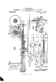
More specifically my invention embodies those novel details of construction, combination and arrangement of parts all of which will be first described in detail, then be specifically pointed out in the appended claims, andl illustrated in the accompanying drawings, in which Figure l, is a plan view of my invention, the explosion engine being indicated to- Seral No. 482,377.
gether with a portion of the frame of a motor vehicle. liig. 2, is a section on the line 22 of Eig. l. Figs. 3, 4, 5 and 6, are detail views of portions of the actuating levers. Fig. 7, is a detail perspective view of the control lever and its rack. Figs. 8, 9 and l0, are detail views showing the parts in various positions. Fig. 1l, is a horizontal section on the line ll-#ll of E ig. l. Fig. 12, is a detail section showing the modified form of band clutch mechanism.
Referring now to the accom anying drawings in which like letters an numerals of reference indicate like parts in all of the figures, l designates the frame of a motor vehicle and 2, the rear axle thereof, which carries the running Wheels, (not shown) and the sprocket 2a, around which the drive chain 8 passes. V
4 represents an explosion engine of any approved type, which may be located in any position on the motor vehicle frame, either to lie under the seat or in the tonneau, or in any other convenient position, as the position of the engine 4 forms no part of my present invention. The engine 4 has its drive or crank shaft 5 extended to pass through bearings 5a5b in the frame l and upon the shaft 5 is a sleeve 6, which carries a small pinion 6, a large pinion 6b and a grooved clutch member 6C, the sleeve 6 with its gears and clutch member being shiftable on the shaft 5 and keyed to turn therewith, see F ig. 1. The sleeve 6 with its gears 6a-6" and its clutch member 6c will be hereinafter termed the double shiftable gearmember.7 8O designates another sleeve on the shaft 5, loosely mounted thereon, so as to be susceptible of being turned independently of the shaft 5 and the sleeve 8O carries a master gear 7a and a friction clutch 7 b which has a grooved portion 7F for a purpose presently to appear, the friction clutch 7b coperatin with the friction surface 8b of the sproc et clutch 8aL that is loosely mounted on the shaft 5 and around which the endless chain 8 passes. The sprocket clutch 8 has a second clutch face 8c that cooperates with the friction clutch 9 that is keyed to turn with the shaft 5, but is slidable thereon, the clutch 9 having a clutch surface 9a to coperate with the sprocket clutch 8 and a grooved portion 9b for a purpose hereinafter explained.
10 designates a pivot upon which a series .tate'therewith `The gears l17 and 18 copof levers 11, 12, 13 and 14 are pivoted, the levers 11, 12, 13 and 14 being the actuating levers for actuating the gears and clutches. The lever 11 is secured to a rod 11X that passes through'bearings' 11y and carries a clutch fork 11z to enter the groove portion *7 of the clutch on the sleeve 7, so that when r the lever 11 `is rocked, the clutch .7b will be shifted longitudinally on the shaft 5. The gears 7a and 19 are always in mesh as the sleeve 7 does not shift on the shaft 5. The lever 12 carries a clutch fork 12X that projects into the groove 6C of the double shiftable gear member and upon movement of the lever 12 the double shiftable gear will be shifted longitudinally on the shaft 5. The lever 13 is connected to a rod 13x that passes 'through bearings 13y and carries a clutch fork 13z that enters the groove 9b in the clutch 9 so that when the lever 13 is operated the clutch 9 will be actuated thereby. e The lever 14 connects through a rod 14x with a bell crank lever 14y that in turn connects through a rod 15X with theV timing device 15y wherebyV the movement of the lever 14 will actuate the timing device 15VY accOrClingly. The timing device 15y may beV of any approved construction, as the same,
per se, forms no part of my present invention. e Y K ledesignates a countershaft mounted in bearings 16a and carrying a master gear 17, an intermediate gear 18 and a smaller gear 19, the gears 17, 18 and 19 being keyed in a Xed position on theY countershaft 16 to roerate respectively with the gears 6a6b of the double shiftable gear member, the gear 17 being cooperatively connected at times with the gear 6a through a counterpinion 2O for a purpose presently to appear.
' Each of the levers 11, 12, 13 and 1,4 have projections 11a, 12a, 13a and 14a at their for.- ward ends that pass between spacing bars 21a, in a bearing 21 and spacing washers 22 are interposed at the pivotrlO, as indicated in Fig. 2,. Y
Each of the levers 11, 12, 13 and 14 is provided at their forward ends with slots 11b, 12b, 13b and 14h, the slots being so designed that the proper motion will be impartedV to the levers 11, 12, 13 and 14, to actuate their respective clutch or gear members, and the levers are actuated through the medium of a control lever 2,3 that is fulcrumed at 23a to the steering post 25, or any other suitable part of the vehicle, and the lever 23 has its lower end 23b projecting through the slots 11a, 12a, 13n and 14a of the levers 1112, 13 and 14, respectively.
A rac 24 coperates with the lever 23 and a pawl 23Xcarried thereby, to hold the lever 23 in its various adjusted positions, the rack 24 being provided with a series of notches to `receive the pawl 23?, tlievnotches designatingA "i reverse, out 'of gear,
slow speed forward, out of gear forward high speed forward set as shown in Figs. 5 and 7 ofthe drawings.
So far as described, the manner in which my invention operates will be best explained as follows,-Assume the parts to be in position shown in Fig, 1, vwith the' lever 23 set in the out of gear notch 24a, of the rack 24, then all of the gears and clutches will be operatively disconnected. Now, supposing the operator desires to reverse his machine, it is only 'necessary to move the lever 23 until 'the pawl 23X rests in the reverse notch 24b of the rack-24, when the portion 23b of the leverY 23 will be at the eXtreme rearward limit of the slots 11", 12b, 13b and 14b of the levers 11, 12, 13 and 14, respectively. At this time the parts will be' in the position shown in Fig. 10, of the drawings, with the gears 6a and 17 in mesh and the gears 7a and 19 in mesh, while the clutch 7h will be in engagement with the sprocket clutch 8a and cause the sprocket clutch 8a to rotate with the sleeve7. Assuming the engine 4 to be rotating in a counterclockwise direction in Fig. 1, the motion thereof will be imparted to the shaft 16 to cause it to rotate in the same direction, but at a slower speed. As the gears 19 and 7a are in mesh the sleeve 7 will be rotated on the shaft 5 in a direction opposite to the rotation of the shaft 6, thereby causing `the sprocket chain 3 to be moved in the direction of the arrow in Fig. 10 and impart a reverse motion to the shaft of the motor vehicle.
e Now assume that it is desired to run the vehicleat a slow forward speed, the operator moves the lever 23 with the pawl 23X into the notch 24crof the rack 24 when the end 23b of the lever 23 will be about midway the ends of the slots of the levers 11, 12, 13 and 14, kas shown in Fig. 9 of the drawings, and when the parts are in this position the gears 7 a and 19 are in mesh, the gears 7a and` 19 being always in mesh, the clutch 7 b and sprocket clutch 8a are engaged and the gears 6b and 18 are in mesh, thus as the shaft 5 rotates in the direction of the arrow in Fig. 9, the motion thereof will be imparted to the shaft 16 to cause it to rotate in a direction reverse to that of the shaft 5, and hence the sleeve 7 will rotate in the same direction as the rshaft 5, but at a slower speed, thus imparting a motion to the sprocket 3 in the direction of the arrow in Fig. 9, at a slower speed.
Now assume that it is desired to drive the vehicle ata fast or high speed forward, the operator continues to move the lever 23 un til the pawl/ 23X is in one of the notches 24d of the rack 24, at which times the parts will be in the position shown in Fig. 8, with the double shiftable gear out of operative action, as well as the clutch 7 b. `At this the lever 23 from the rst notch 24d to theI last, so as to bring the lever 23b to the extreme forward limit of the slots in the levers 11, 12, 13, 14 simply causes the lever 14 to continue to shift the timing device 15y and speed up the engine.
In Fig. 12, I have shown a modified construction of clutch in which the sprocket gear 8 is secured to two clutch rims 28 one of which incloses a clutch ring 28b of the split ring type, that is actuated by the cam 33 having a lever 23 that is actuated by the clutch 30 that corresponds with the clutch 7b in Fig. 11 of the drawings. The clutch 30 is shiftable on the sleeve 8O and the sleeve 8O carries a gear 7a, as before. The other clutch rim 28 receives a split ring 28c that cooperates with a cam 34 having a lever portion 32z that is actuated by the bevel face 29aL of the shifting clutch 29b to receive the fork 13" of the clutch shifting mechanism. The shifting clutch 29 is shiftable on the sleeve 29X that is keyed to the shaft 5 and the shifting clutch 29 corresponds with the shifting clutch 9, see Fig. 11. It is also to be noted that at each movement of the controlling lever the speed of the engine is changed to conform to the requirements at that particular time. In other words when out of gear the engine must necessarily run very slowly, but the very preparation to throw it into gear for any speed brings the engine up to a working capacity or vice versa. This is done through the shifting of the timing device.
From the foregoing description taken in connection with the accompanying drawings it is thought the complete construction, operation and numerous advantages of my invention will be readily understood by those skilled in the art to which the invention appertains, and I desire to say that my gear transmission mechanism may be used not only on motor vehicles but with any type of machinery where reversing' and variable speed gearing is required.
I make no claim to the transmission gear mechanism and its operating mechanism per se in this application since that forms the subject-matter of my original application filed Aug. 13, 1908, Ser. No. 448,282, and of which original application the present application is a divisional part. It will also be apparent that changes in the details of construction and design of parts may be readily made without departing from the essence and spirit of my invention, which resides in providing a single operating lever for operating the actuating levers to shift the gears in proper cooperative relations.
hat I claim is: 1. In an explosion engine having a drive shaft, a driven shaft, variable speed gear connections between said drive and driven shafts, said gear connections including shiftable gear members, lever mechanisms for actuating said shiftable gear members, a timer for said engine, a lever mechanism for actuating said timer, and a single control lever directly and coperatively engaging all of the aforesaid lever mechanisms for controlling all of said actuating levers.
2. In a motor vehicle, an explosion engine having a drive shaft, a driven shaft and varia-ble speed connections between the drive shaft and the driven shaft, combined with means for actuating said variable speed gears, and means for increasing and decreasing the speed of the engine together with a lever mechanism for actuating said last named means, and a single control lever directly engaging all of the aforesaid lever mechanisms for operating all of said actuating mechanisms.
3. In a motor vehicle, an explosive engine having a drive shaft, a driven shaft and gear connections between the drive and driven shafts, combined with lever operated means for connecting and disconnecting said gears with said engine drive shaft, lever operated means for changing the speed of operation of said engine, lever operated means for shifting the connection between the drive and driven shafts to reverse the direction of rotation of the driven shaft, lever operated means for changing the speed of rotation of the driven shaft without changing the speed of rotation of the drive shaft, and a single control lever directly cooperatively engaging the levers of said lever operated mechanisms for simultaneously cooperatively moving all ofthe levers of said lever operated mechanisms to simultaneously control all of said means.
4. In a drive mechanism for motor vehicles and the like, a variable speed transmission gear mechanism comprising a series of variable speed gears, a series of actuating lever mechanisms for moving said gears into and out of operation, an explosion engine cooperating with the variable speed gear mechanism, a driven shaft coperatively connected with said variable speed gear mechanism, means forming part of the explosion engine for changing its speed, an actuating lever for actuating said speed changing means of the engine, and a single control lever directly coperatively engaging and operating all of the actuating levers to set any of the gear mechanisms into operative relation and simultaneously change the speed of operation of the engine.
5. In a transmission mechanism for motor vehicles and the like, a driven shaft, a driv- Vmechanism of the engine, and a single coning engine, a variable speed transmission trol lever directly engaging and operating gear connecting the driving engine and the all of the actuating levers simultaneously. 10 driven shaft, leversV for actuating the vari- CHARLES A. MCKIEARNAN.
5 able speed gear mechanism, speed changing Titnessesz Y mechanism for said driving engine, lever W. H. GNTHER, devices for actuating said speed changingv W. L. MANCHESTER.
Priority Applications (1)
| Application Number | Priority Date | Filing Date | Title |
|---|---|---|---|
| US482377A US960573A (en) | 1908-08-13 | 1909-03-09 | Transmission-gear mechanism for motor-vehicles and the like. |
Applications Claiming Priority (2)
| Application Number | Priority Date | Filing Date | Title |
|---|---|---|---|
| US44828208A US960572A (en) | 1908-08-13 | 1908-08-13 | Transmission-gearing. |
| US482377A US960573A (en) | 1908-08-13 | 1909-03-09 | Transmission-gear mechanism for motor-vehicles and the like. |
Publications (1)
| Publication Number | Publication Date |
|---|---|
| US960573A true US960573A (en) | 1910-06-07 |
Family
ID=3028971
Family Applications (1)
| Application Number | Title | Priority Date | Filing Date |
|---|---|---|---|
| US482377A Expired - Lifetime US960573A (en) | 1908-08-13 | 1909-03-09 | Transmission-gear mechanism for motor-vehicles and the like. |
Country Status (1)
| Country | Link |
|---|---|
| US (1) | US960573A (en) |
Cited By (1)
| Publication number | Priority date | Publication date | Assignee | Title |
|---|---|---|---|---|
| US2634710A (en) * | 1949-09-02 | 1953-04-14 | Fiat Spa | Propelling unit for motor vehicles |
-
1909
- 1909-03-09 US US482377A patent/US960573A/en not_active Expired - Lifetime
Cited By (1)
| Publication number | Priority date | Publication date | Assignee | Title |
|---|---|---|---|---|
| US2634710A (en) * | 1949-09-02 | 1953-04-14 | Fiat Spa | Propelling unit for motor vehicles |
Similar Documents
| Publication | Publication Date | Title |
|---|---|---|
| US960573A (en) | Transmission-gear mechanism for motor-vehicles and the like. | |
| US1396512A (en) | Change-speed-gear transmission | |
| US1479292A (en) | Change-speed mechanism | |
| US1291542A (en) | Transmission-gearing. | |
| US861082A (en) | Variable-speed mechanism. | |
| US1658767A (en) | Speed-reduction gear | |
| US960572A (en) | Transmission-gearing. | |
| US1012119A (en) | Gearing. | |
| US662306A (en) | Power-transmitting device. | |
| US904868A (en) | Transmission-gear for motor-vehicles. | |
| US881987A (en) | Variable-speed mechanism. | |
| US870107A (en) | Transmission-gear. | |
| US688516A (en) | Changeable gearing. | |
| US848368A (en) | Transmission mechanism. | |
| US875321A (en) | Transmission mechanism. | |
| US807771A (en) | Speed changing and transmission gearing. | |
| US1208329A (en) | Transmission mechanism. | |
| US1623213A (en) | Transmission gearing | |
| US1086674A (en) | Power-transmitting device. | |
| US995915A (en) | Change-gear mechanism. | |
| US937321A (en) | Speed-changing mechanism. | |
| US570203A (en) | Gear for motocycles | |
| US1347804A (en) | Transmission-gear | |
| US1930823A (en) | Vehicle propelling mechanism | |
| US953846A (en) | Reversible transmission-gearing. |