US9604756B1 - Process for testing a compressor or a combustor of a gas turbine engine using a large compressed air storage reservoir - Google Patents
Process for testing a compressor or a combustor of a gas turbine engine using a large compressed air storage reservoir Download PDFInfo
- Publication number
- US9604756B1 US9604756B1 US15/200,057 US201615200057A US9604756B1 US 9604756 B1 US9604756 B1 US 9604756B1 US 201615200057 A US201615200057 A US 201615200057A US 9604756 B1 US9604756 B1 US 9604756B1
- Authority
- US
- United States
- Prior art keywords
- compressed air
- testing
- combustor
- engine
- compressor
- Prior art date
- Legal status (The legal status is an assumption and is not a legal conclusion. Google has not performed a legal analysis and makes no representation as to the accuracy of the status listed.)
- Active
Links
Images


Classifications
-
- H—ELECTRICITY
- H04—ELECTRIC COMMUNICATION TECHNIQUE
- H04B—TRANSMISSION
- H04B1/00—Details of transmission systems, not covered by a single one of groups H04B3/00 - H04B13/00; Details of transmission systems not characterised by the medium used for transmission
- H04B1/06—Receivers
- H04B1/16—Circuits
- H04B1/1646—Circuits adapted for the reception of stereophonic signals
-
- B—PERFORMING OPERATIONS; TRANSPORTING
- B65—CONVEYING; PACKING; STORING; HANDLING THIN OR FILAMENTARY MATERIAL
- B65D—CONTAINERS FOR STORAGE OR TRANSPORT OF ARTICLES OR MATERIALS, e.g. BAGS, BARRELS, BOTTLES, BOXES, CANS, CARTONS, CRATES, DRUMS, JARS, TANKS, HOPPERS, FORWARDING CONTAINERS; ACCESSORIES, CLOSURES, OR FITTINGS THEREFOR; PACKAGING ELEMENTS; PACKAGES
- B65D19/00—Pallets or like platforms, with or without side walls, for supporting loads to be lifted or lowered
- B65D19/02—Rigid pallets with side walls, e.g. box pallets
- B65D19/06—Rigid pallets with side walls, e.g. box pallets with bodies formed by uniting or interconnecting two or more components
- B65D19/14—Rigid pallets with side walls, e.g. box pallets with bodies formed by uniting or interconnecting two or more components made wholly or mainly of wood
- B65D19/16—Collapsible pallets
-
- F—MECHANICAL ENGINEERING; LIGHTING; HEATING; WEAPONS; BLASTING
- F01—MACHINES OR ENGINES IN GENERAL; ENGINE PLANTS IN GENERAL; STEAM ENGINES
- F01D—NON-POSITIVE DISPLACEMENT MACHINES OR ENGINES, e.g. STEAM TURBINES
- F01D17/00—Regulating or controlling by varying flow
- F01D17/02—Arrangement of sensing elements
-
- F—MECHANICAL ENGINEERING; LIGHTING; HEATING; WEAPONS; BLASTING
- F01—MACHINES OR ENGINES IN GENERAL; ENGINE PLANTS IN GENERAL; STEAM ENGINES
- F01D—NON-POSITIVE DISPLACEMENT MACHINES OR ENGINES, e.g. STEAM TURBINES
- F01D21/00—Shutting-down of machines or engines, e.g. in emergency; Regulating, controlling, or safety means not otherwise provided for
- F01D21/003—Arrangements for testing or measuring
-
- F—MECHANICAL ENGINEERING; LIGHTING; HEATING; WEAPONS; BLASTING
- F01—MACHINES OR ENGINES IN GENERAL; ENGINE PLANTS IN GENERAL; STEAM ENGINES
- F01D—NON-POSITIVE DISPLACEMENT MACHINES OR ENGINES, e.g. STEAM TURBINES
- F01D25/00—Component parts, details, or accessories, not provided for in, or of interest apart from, other groups
- F01D25/28—Supporting or mounting arrangements, e.g. for turbine casing
- F01D25/285—Temporary support structures, e.g. for testing, assembling, installing, repairing; Assembly methods using such structures
-
- F—MECHANICAL ENGINEERING; LIGHTING; HEATING; WEAPONS; BLASTING
- F01—MACHINES OR ENGINES IN GENERAL; ENGINE PLANTS IN GENERAL; STEAM ENGINES
- F01D—NON-POSITIVE DISPLACEMENT MACHINES OR ENGINES, e.g. STEAM TURBINES
- F01D5/00—Blades; Blade-carrying members; Heating, heat-insulating, cooling or antivibration means on the blades or the members
- F01D5/02—Blade-carrying members, e.g. rotors
-
- F—MECHANICAL ENGINEERING; LIGHTING; HEATING; WEAPONS; BLASTING
- F04—POSITIVE - DISPLACEMENT MACHINES FOR LIQUIDS; PUMPS FOR LIQUIDS OR ELASTIC FLUIDS
- F04D—NON-POSITIVE-DISPLACEMENT PUMPS
- F04D27/00—Control, e.g. regulation, of pumps, pumping installations or pumping systems specially adapted for elastic fluids
- F04D27/001—Testing thereof; Determination or simulation of flow characteristics; Stall or surge detection, e.g. condition monitoring
-
- F—MECHANICAL ENGINEERING; LIGHTING; HEATING; WEAPONS; BLASTING
- F04—POSITIVE - DISPLACEMENT MACHINES FOR LIQUIDS; PUMPS FOR LIQUIDS OR ELASTIC FLUIDS
- F04D—NON-POSITIVE-DISPLACEMENT PUMPS
- F04D29/00—Details, component parts, or accessories
- F04D29/26—Rotors specially for elastic fluids
- F04D29/32—Rotors specially for elastic fluids for axial flow pumps
- F04D29/321—Rotors specially for elastic fluids for axial flow pumps for axial flow compressors
-
- G—PHYSICS
- G01—MEASURING; TESTING
- G01M—TESTING STATIC OR DYNAMIC BALANCE OF MACHINES OR STRUCTURES; TESTING OF STRUCTURES OR APPARATUS, NOT OTHERWISE PROVIDED FOR
- G01M9/00—Aerodynamic testing; Arrangements in or on wind tunnels
- G01M9/02—Wind tunnels
- G01M9/04—Details
-
- F—MECHANICAL ENGINEERING; LIGHTING; HEATING; WEAPONS; BLASTING
- F02—COMBUSTION ENGINES; HOT-GAS OR COMBUSTION-PRODUCT ENGINE PLANTS
- F02C—GAS-TURBINE PLANTS; AIR INTAKES FOR JET-PROPULSION PLANTS; CONTROLLING FUEL SUPPLY IN AIR-BREATHING JET-PROPULSION PLANTS
- F02C6/00—Plural gas-turbine plants; Combinations of gas-turbine plants with other apparatus; Adaptations of gas- turbine plants for special use
- F02C6/14—Gas-turbine plants having means for storing energy, e.g. for meeting peak loads
- F02C6/16—Gas-turbine plants having means for storing energy, e.g. for meeting peak loads for storing compressed air
-
- F—MECHANICAL ENGINEERING; LIGHTING; HEATING; WEAPONS; BLASTING
- F05—INDEXING SCHEMES RELATING TO ENGINES OR PUMPS IN VARIOUS SUBCLASSES OF CLASSES F01-F04
- F05B—INDEXING SCHEME RELATING TO WIND, SPRING, WEIGHT, INERTIA OR LIKE MOTORS, TO MACHINES OR ENGINES FOR LIQUIDS COVERED BY SUBCLASSES F03B, F03D AND F03G
- F05B2220/00—Application
- F05B2220/30—Application in turbines
- F05B2220/302—Application in turbines in gas turbines
-
- F—MECHANICAL ENGINEERING; LIGHTING; HEATING; WEAPONS; BLASTING
- F05—INDEXING SCHEMES RELATING TO ENGINES OR PUMPS IN VARIOUS SUBCLASSES OF CLASSES F01-F04
- F05B—INDEXING SCHEME RELATING TO WIND, SPRING, WEIGHT, INERTIA OR LIKE MOTORS, TO MACHINES OR ENGINES FOR LIQUIDS COVERED BY SUBCLASSES F03B, F03D AND F03G
- F05B2260/00—Function
- F05B2260/83—Testing, e.g. methods, components or tools therefor
-
- F—MECHANICAL ENGINEERING; LIGHTING; HEATING; WEAPONS; BLASTING
- F05—INDEXING SCHEMES RELATING TO ENGINES OR PUMPS IN VARIOUS SUBCLASSES OF CLASSES F01-F04
- F05D—INDEXING SCHEME FOR ASPECTS RELATING TO NON-POSITIVE-DISPLACEMENT MACHINES OR ENGINES, GAS-TURBINES OR JET-PROPULSION PLANTS
- F05D2220/00—Application
- F05D2220/30—Application in turbines
- F05D2220/32—Application in turbines in gas turbines
- F05D2220/323—Application in turbines in gas turbines for aircraft propulsion, e.g. jet engines
-
- F—MECHANICAL ENGINEERING; LIGHTING; HEATING; WEAPONS; BLASTING
- F05—INDEXING SCHEMES RELATING TO ENGINES OR PUMPS IN VARIOUS SUBCLASSES OF CLASSES F01-F04
- F05D—INDEXING SCHEME FOR ASPECTS RELATING TO NON-POSITIVE-DISPLACEMENT MACHINES OR ENGINES, GAS-TURBINES OR JET-PROPULSION PLANTS
- F05D2260/00—Function
- F05D2260/83—Testing, e.g. methods, components or tools therefor
-
- F—MECHANICAL ENGINEERING; LIGHTING; HEATING; WEAPONS; BLASTING
- F23—COMBUSTION APPARATUS; COMBUSTION PROCESSES
- F23R—GENERATING COMBUSTION PRODUCTS OF HIGH PRESSURE OR HIGH VELOCITY, e.g. GAS-TURBINE COMBUSTION CHAMBERS
- F23R2900/00—Special features of, or arrangements for continuous combustion chambers; Combustion processes therefor
- F23R2900/00019—Repairing or maintaining combustion chamber liners or subparts
-
- G—PHYSICS
- G01—MEASURING; TESTING
- G01M—TESTING STATIC OR DYNAMIC BALANCE OF MACHINES OR STRUCTURES; TESTING OF STRUCTURES OR APPARATUS, NOT OTHERWISE PROVIDED FOR
- G01M15/00—Testing of engines
- G01M15/14—Testing gas-turbine engines or jet-propulsion engines
-
- G—PHYSICS
- G01—MEASURING; TESTING
- G01M—TESTING STATIC OR DYNAMIC BALANCE OF MACHINES OR STRUCTURES; TESTING OF STRUCTURES OR APPARATUS, NOT OTHERWISE PROVIDED FOR
- G01M17/00—Testing of vehicles
- G01M17/007—Wheeled or endless-tracked vehicles
-
- G—PHYSICS
- G01—MEASURING; TESTING
- G01M—TESTING STATIC OR DYNAMIC BALANCE OF MACHINES OR STRUCTURES; TESTING OF STRUCTURES OR APPARATUS, NOT OTHERWISE PROVIDED FOR
- G01M9/00—Aerodynamic testing; Arrangements in or on wind tunnels
- G01M9/02—Wind tunnels
-
- Y—GENERAL TAGGING OF NEW TECHNOLOGICAL DEVELOPMENTS; GENERAL TAGGING OF CROSS-SECTIONAL TECHNOLOGIES SPANNING OVER SEVERAL SECTIONS OF THE IPC; TECHNICAL SUBJECTS COVERED BY FORMER USPC CROSS-REFERENCE ART COLLECTIONS [XRACs] AND DIGESTS
- Y02—TECHNOLOGIES OR APPLICATIONS FOR MITIGATION OR ADAPTATION AGAINST CLIMATE CHANGE
- Y02E—REDUCTION OF GREENHOUSE GAS [GHG] EMISSIONS, RELATED TO ENERGY GENERATION, TRANSMISSION OR DISTRIBUTION
- Y02E60/00—Enabling technologies; Technologies with a potential or indirect contribution to GHG emissions mitigation
- Y02E60/16—Mechanical energy storage, e.g. flywheels or pressurised fluids
Definitions
- the present invention relates generally to an apparatus and a process for testing a component of a gas turbine engine, especially for a large aero gas turbine engine, and for a process for testing a large industrial gas turbine engine that require large flow capacity and pressure ratios.
- a large frame heavy duty industrial gas turbine (IGT) engine is typically used to drive an electric generator and produce electrical energy. These engines can produce over 200 MW of electric power.
- An IGT engine will have a compressor with multiple rows or stages of rotor blades and stator vanes, a combustor with multiple can combustors arranged in an annular array (also referred to as a can annular combustor), and a turbine with multiple rows of rotor blades and stator vanes.
- An aero engine typically has an annular combustor instead of multiple can combustors arranged in an annular array as in the IGT engines.
- CAES compressed air energy storage
- Testing of a component of a large frame heavy duty industrial gas turbine engine is also required.
- Each of the components of an engine requires testing.
- the compressor, the combustor or the turbine can be tested as a separate unit from the engine.
- a large volume of compressed air at high pressure (15-100 bars) is required to be supplied to the combustor to be burned with a fuel for testing.
- One or more compressors are required to produce this large volume of compressed air.
- a large electric motor with a power output of 20-200 MW and over is required to drive the compressor or compressors.
- testing of combustors requires a large capital expense and maintenance requirements.
- a component of a large industrial or aero gas turbine engine is to be tested, such as a combustor module or a turbine module or a compressor module
- the entire engine is operated just to test that one component module.
- the entire engine is required to be operated in order to produce the conditions required to test that component module.
- it is very costly to test a single component module in a gas turbine engine when the entire engine is to be operated.
- a load is connected to the turbine in order to create a resistance during the testing process. As described above in the entire engine testing process, this load is typically lost or difficult to dissipate.
- the compressed air produced during the testing process is wasted due to the high cost of storing the compressed air for future use.
- the energy produced in the testing process of a compressor module is also wasted.
- An airfoil that requires a high Mach number of air flow for testing is typically supplied with compressed air from a compressed air storage tank that is relatively small and very heavy in construction to withstand the high pressures. Because of the limited size of the compressed air tank, the testing period is on the order of a few seconds which limits the accuracy of the test data and the types of data that can be measured.
- GTL R&TD Gas Turbine Laboratory
- the National Research Council Institute for Aerospace Research (IAR) Gas Turbine Laboratory (GTL) already performs similar combustion research and technology demonstration.
- GTL R&TD is on both conventional and alternative fuels but at lower pressure ratios and air mass flow rates than are required for future technology development, demonstration and validation.
- the minimum facility air mass flow rate and operating pressure ratio that would be sufficient for this facility would be 150 lb/sec at a pressure ratio of 60:1. This requires a compressor drive power of 80 MW although redundancy would be a highly desirable facility attribute.
- the Compressor Institute design standard dictate that no more than 40 MW of compressor capacity be driven by one shaft.
- This size test facility is estimated to cost around $200 Million.
- a more desirable facility capacity would provide 300-550 lb/sec of air at a minimum pressure ratio of 60:1, but would require a compressor drive capacity of around 150 MW.
- a full capacity facility would deliver 550 lb/sec of air at the 60:1 pressure ratio, but with a capital investment in excess of $600 Million.
- Transient blow down testing is a technique that has been used for many years in aerospace testing. This technique is used to reduce the size and cost of compression and vacuum pumps required to develop the conditions required for a test. For example, a compressor can be run for days or longer to fill a tank to very high pressure and/or a vacuum chamber to very low pressure. The gas is then released for testing. Depending on the mass-flow required during the test, the actual test time can vary from milliseconds up to many minutes. While the cost of the compression and vacuum equipment is kept low using the blow down facility idea, the cost of the pressure and vacuum tanks become very large. NASA Langley has some of the largest high pressure tanks available for testing to create very high Mach number flows.
- An apparatus and process for testing a large aero or industrial gas turbine engine or a single component of an engine where the engine testing facility is established close to a compressed air energy storage (CAES) facility or to an underground cavern that can store compressed air so that the engine during testing can supply the underground compressed air storage reservoir with compressed air, or the underground compressed air storage reservoir can supply the engine or component module testing facility with compressed air for the testing of an engine or an engine component module such as a compressor module or a combustor module or a turbine module.
- CAES compressed air energy storage
- the turbine For testing of an IGT engine, the turbine is connected to drive a compressor so that the load from the engine during testing is used to drive the compressor to produce compressed air that is then stored within the storage cavern or CAES facility for use in peak power production later or for other engine testing requirements. Thus, no disruption to the electric grid is produced, and no energy from the engine testing is wasted.
- Compressed air from the storage cavern or CAES facility can be burned with a fuel to produce the hot gas stream for testing within the turbine, and the turbine can be used to drive a compressor to resupply the storage cavern or CAES facility for later use.
- the large volume and high pressure compressed air can be supplied from the CAES facility or storage cavern for use in testing the component. Therefore, a large capital investment in equipment and a building is not required since the infrastructure already exists at the CAES power plant.
- the engine or component module testing CAES facility can be located near to an underground cavern (such as a salt dome) or large geologic cavern that can be used to store the compressed air.
- the compressor can be one-tenth of the size normally required to supply this large of a volume of compressed air since the smaller compressor can be operated for a longer period of time (for example 72 hours) to supply the required volume and pressure of compressed air in the reservoir of the CAES or testing CAES facility.
- the storage caverns facility can also be used to store gaseous fuels such as CH 4 or H 2 in the underground cavern or mine such as an old salt mine.
- a high Mach number test can also be performed using the CAES facility or storage cavern to store a vacuum (a negative pressure in relation to atmospheric pressure) within one of the caverns or mines.
- the large volume of low pressure (vacuum) air can be used to vary a downstream pressure for the high Mach number testing of vehicles or engines in a wind tunnel with a low capital equipment cost.
- the testing facility can be connected to a high pressure cavern upstream and to a negative pressure cavern downstream in order to produce a very high pressure differential for the test facility in order to test an aero component.
- the lower pressure at the outlet of the test object can be subjected to an ejector using the compressed air from the underground storage reservoir to produce a lower pressure.
- the engine For testing an industrial or aero gas turbine engine, the engine is connected to drive multiple compressors each producing different pressures and each being connected to a separate underground reservoir to hold the compressed air at different pressures.
- One reservoir might be used to store relatively low pressure compressed air
- a second reservoir might be used to store medium pressure compressed air
- a third reservoir might be used to store relatively high pressure compressed air.
- the reservoir with the minimum pressure can be used instead of wasting pressurized air that requires decreasing of the pressure.
- the cost of the storage volume has always limited the test time available from blow down tests and mass-flow rate during the test time.
- the prior art has always been to use relatively small manmade tanks for storing the high pressure air or the vacuum.
- Prior art low pressure storage tanks exist of around 50 meters in diameter that can store a low pressure gas.
- a cylinder tank made of carbon fiber of about 36 inches in diameter can store up to 200 bar of pressurized gas.
- the present invention is to use a manmade solution mined cavern to form a very large underground cavern to store highly compressed air for aerospace and gas turbine engine testing or component module testing.
- a geographic salt dome cavern can be thousands of time larger than the largest manmade tank and built using solution mining at a small fraction of the cost.
- the use of a single or multiple salt dome caverns or similar geographic cavern to store and release gases to and from a series of different cavern pressures can significantly reduce the cost of aerodynamic wind tunnel and gas turbine engine or component module testing.
- the caverns can be mined at various depths to be best adapted to meeting the storage pressure range requirement of a particular cavern.
- flow conditions previously thought unaffordable therefore never previously available to the industry for testing can now become part of the standard test protocol.
- the underground compressed air storage reservoir and the test facility for testing a gas turbine engine or a component of an engine includes a non-vitiating heat exchanger to preheat the compressed air from the reservoir to produce non-vitiated compressed air for use in a test component such as a combustor in order to more accurately test the component.
- the heat exchanger can be electric or use fuel and air to produce a hot gas that does not mix with the compressed air from the reservoir in order to preheat the compressed air to the required temperature and pressure for testing the component without decreasing the oxygen content of the compressed air.
- the non-vitiating heater can be replaced with an air turbine that is driven by compressed air from the underground storage reservoir, where the air turbine drives a real compressor that will produce the required compressed air at the design pressure and temperature that is burned with a fuel in a combustor for testing of the combustor.
- a compressor can also be tested with this design in that the air turbine is used to drive the compressor during the testing phase.
- FIG. 1 shows a schematic view of a large gas turbine engine test facility using an underground compressed air reservoir of the present invention.
- FIG. 2 shows a schematic view of a compressed air energy storage facility with a large frame heavy duty industrial gas turbine engine located nearly for testing of the engine or for testing a component of a gas turbine engine of the present invention.
- FIG. 3 shows a schematic view of a turbine component of an engine for testing according to the present invention.
- FIG. 4 shows a schematic view of a compressor component of an engine for testing according to the present invention.
- FIG. 5 shows a schematic view of a combustor component of an engine for testing according to the present invention.
- FIG. 6 shows a schematic view of an aero vehicle or aero component within an air tunnel for testing according to the present invention.
- FIG. 7 shows a schematic view of an engine testing facility of the present invention with a thermal heat storage device.
- FIG. 8 shows a schematic view of an engine testing facility of the present invention with three separate compressed air reservoirs to hold different pressures of compressed air.
- FIG. 9 shows an embodiment of the present invention in which a non-vitiated air heater is used to preheat the compressed air from the cavern prior to entering a test component.
- FIG. 10 shows an embodiment of the present invention in which an electric heater is used to preheat the compressed air in the FIG. 9 embodiment.
- FIG. 11 shows an embodiment of the present invention with a non-vitiated air heater that uses a fuel to preheat the compressed air for the FIG. 8 embodiment.
- FIG. 12 shows an embodiment of the present invention for a high Mach number test in which the preheated air from the non-vitiated air heater in FIG. 11 is further heated by direct injection of a fuel into the high temperature compressed air.
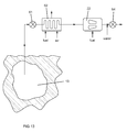
- FIG. 13 shows another embodiment of the present invention where compressed air from the storage reservoir 13 is supplied to a heater 62 to produce non-vitiated air that is delivered into a combustor 22 .
- FIG. 14 shows a variation of the test facility of FIG. 13 in which a high Mach number heater 81 is used between the non-vitiated compressed air heater 62 and the combustor 22 that is to be tested.
- FIG. 15 shows another embodiment of the present invention in which a test facility can test a component such as a combustor at high altitude where the pressure of the air is low.
- FIG. 16 shows another embodiment of the present invention in which the test facility is used to test a component such as a combustor at a cold environment.
- FIG. 17 shows another embodiment of the present invention in which the test facility is used to test a compressor under normal operating conditions.
- FIG. 18 shows another embodiment of the present invention in which the test facility is used to test a compressor under a cold environment such as high altitude.
- FIG. 19 shows another embodiment of the present invention in which the test facility is used to test a turbine under warm air conditions.
- FIG. 20 shows another embodiment of the present invention in which the test facility is used to test a combustor at full load conditions.
- FIG. 21 shows another embodiment of the present invention in which the test facility is used to test a turbine at high altitude conditions.
- FIG. 22 shows another embodiment of the present invention in which the facility is used to testing a turbine at high altitude conditions where the turbine drives a generator as the load.
- FIG. 23 shows another embodiment of the present invention in which an air turbine is used to drive a compressor to produce high pressure and high temperature compressed air for test of a combustor.
- FIG. 24 shows another embodiment of the present invention in which an air turbine is used to drive a compressor for testing of a compressor.
- FIG. 25 shows another embodiment of the present invention in which the test facility is used to test a component such as a full-sized aircraft in a wind tunnel.
- FIG. 26 shows a test facility according to one embodiment of the present invention using a storage reservoir such as an underground salt dome to provide long duration, full scale combustor, augmenter, and hypersonic propulsion system tests.
- a storage reservoir such as an underground salt dome to provide long duration, full scale combustor, augmenter, and hypersonic propulsion system tests.
- FIG. 27 shows a CAES (Compressed Air Energy Storage) test facility of the present invention with a cave fill process that includes a number of compressors and intercoolers and an after-cooler formed in series flow that discharges into the cavern.
- CAES Compressed Air Energy Storage
- FIG. 1 A test facility and a process for testing a turbine or combustor component module for an industrial or aero gas turbine engine is shown in FIG. 1 in which compressed air stored within a large underground cavern is used to supply the high flow rate and pressure required for testing an engine or component module under normal engine operating conditions.
- the engine or component module test facility includes a small compressor 11 (small in relation to the compressor used on the actual gas turbine engine in which the combustor is being tested), an electric motor (or a gas or diesel powered engine can be used) or a small gas turbine engine 12 to drive the compressor 11 , an underground compressed air storage reservoir 13 to store compressed air from the compressor 11 , an air pressure regulator valve 14 to control the pressure released from the underground compressed air storage reservoir 13 , an air heater 15 to heat the compressed air flowing from the reservoir 13 to a temperature that would normally be passed into the combustor of the actual engine, a fuel source 17 such as natural gas to be burned with the compressed heated air, a combustor 16 that is to be tested, a hot exhaust gas cooler 18 to cool the hot exhaust gas from the component that is being tested, and an exhaust and silencer 19 to discharge the combustor exhaust.
- the heater 15 is a non-vitiating heater that will produce heated compressed air at a proper temperature for testing in which the oxygen content is at a normal range for atmospheric air.
- the compressed air storage reservoir 13 can be a pre-existing underground storage facility such as an emptied salt cavern, or can be formed from a salt mine using a solution to create a cavity within the salt mine capable of storing compressed air for engine or component module testing. Or, if the engine testing facility is located at a CAES facility, the storage reservoir for the CAES facility can be used as the compressed air source for the engine or engine component testing.
- the storage reservoir 13 must be capable of storing enough compressed air at a high pressure and high flow rate so that the combustor can be properly tested.
- the smaller compressor 11 can be much smaller (such as around one-third the size of one of the larger compressor used in the prior art test facilities.
- the smaller compressor used in the present invention would only cost around $1-10 Million. Also, since the storage tank 13 can be filled over a long period of time, the smaller compressor 11 can be operated for several days to fill the reservoir 13 with enough compressed air for the next test to be performed.
- the pressure regulator valve 14 controls the release of the compressed air from the storage reservoir 13 that will flow into the combustor 16 or test article for testing. Because the compressed air released from the storage reservoir 13 is relatively cold air, the air heater 15 will heat the compressed air to the normal temperature that would be discharged from a required temperature for testing of the combustor or the turbine or other component that is to be tested. Using a fuel to directly heat the compressed air would supply heated compressed air but at a lower oxygen content.
- the test facility of the present invention can be used to test combustors of modern day engines that use the can-annular combustor or the annular combustor or silo combustors.
- Aero engines typically use an annular combustor while industrial engines use an annular arrangement of can combustors commonly referred to as a can-annular combustor.
- these combustors are tested by using only a small section of the combustor because of the symmetry. However, some error is produced even when testing of only a section of the combustor. To produce a full and accurate test of the combustor, the entire combustor must be tested for flow.
- this combustor cannot be sectioned so that a portion of the combustor can be flow tested that would represent the entire combustor.
- the entire combustor should be flow tested and therefore a high flow rate is required.
- the combustor testing can be performed without burning a fuel in the combustor, or can be tested under normal operating conditions by burning the fuel as normal within the combustor by injecting the fuel through the injectors and into the combustor to be burned with the compressed air from the storage tank 13 .
- FIG. 2 shows a CAES facility (includes 41-46) which is located next to a large underground cavern or old salt mine 13 that can be used for storage of compressed air.
- the test engine includes a large industrial gas turbine engine with a compressor 21 , a combustor 22 and a gas turbine 23 to produce mechanical work that is used to drive a compressor 24 to fill the cavern.
- the compressor 24 provides for a load to the engine during testing.
- the power plant can be used to drive a compressor 24 to produce compressed air to be stored within the underground reservoir 13 .
- the load is not wasted but converted into compressed air for storage in the reservoir 13 .
- the stored compressed air is then supplied to the power plant for later use.
- Air line (a) represents compressed air being discharged from the reservoir while air line (b) represents compressed air being delivered to the reservoir 13 .
- Air line (c) represents a lower pressure air such as from a vacuum or an ejector.
- a valve 35 is used to prevent compressed air from discharging from the reservoir 13 and back out through the compressor 24 .
- An IGT engine testing facility is located adjacent to the CAES facility (or cavern) so that the load from the engine that is being tested can be used to produce compressed air for storage in the CAES facility, and the CAES facility can be used to supply compressed air (or a vacuum) to the engine testing facility. With this association, the overall efficiency of both the engine testing facility and the CAES facility will be improved.
- a lower pressure can be produced using a storage reservoir with a vacuum or a storage reservoir with compressed air connected to an ejector that will be described below in more detail.
- the gas turbine 23 is connected to drive a compressor 24 so that the load from the engine during testing is used to drive the compressor 24 to produce compressed air that is then stored within the CAES facility for use in peak power production later or for other engine testing requirements.
- Compressed air from the CAES facility can be burned with a fuel to produce the hot gas stream for running the CAES plant or for testing within the turbine, and the turbine can be used to drive a compressor to resupply the CAES facility for later use.
- Another benefit of the testing facility of FIG. 2 for large engines using the compressed air energy storage reservoir 13 is that the reservoir 13 functions as a load damper in the case when the gas turbine engine trips.
- the air storage reservoir 13 can be made very large in order to allow for a large industrial or aero gas turbine engine to be tested for a long period of time such as a few days and thus store the energy as compressed air. The compressed air produced during this long period of testing can then be used for process generation or other industrial applications in addition to power generation.
- the CAES testing facility can also include an electric motor/electric generator 43 to drive a compressor 41 through a clutch 42 to resupply the reservoir 13 with compressed air.
- the compressed air stored within the reservoir 13 can be used to drive a turbine 46 thru a clutch 44 which drives the electric generator 43 to produce electrical energy.
- An optional combustor 45 can be used to burn the compressed air from the reservoir with a fuel and produce a hot gas stream that is then passed through the turbine 46 to produce electric energy from the generator 43 .
- the large volume and high pressure compressed air can be supplied from the storage reservoir 13 of the CAES facility for use in testing these large gas turbine engine components or as a load on the test article such as the compressor 24 that can resupply the storage reservoir 13 . Therefore, a large capital investment in equipment and a building is not required since the infrastructure already exists at the CAES power plant.
- compressed air from the storage reservoir 13 is used to drive the gas turbine 23 for testing.
- An optional combustor can also be used to produce the hot gas stream and passed through the turbine to recreate a normal operating condition.
- a compressor 24 driven by the gas turbine 23 during testing can be used to provide a load on the turbine 23 during testing that will also produce compressed air that can be resupplied to the reservoir 13 .
- a heat source 51 can be used to heat up the compressed air coming from the cavern 13 .
- Compressed air from the reservoir can be used to drive an air turbine 23 that then drives the compressor 24 that will produce compressed air at a high pressure and a high temperature for testing a combustor 22 with the proper pressure and temperature of the compressed air without having to heat the compressed air from the reservoir 13 .
- This design will eliminate the need for a non-vitiating heater.
- a compressor is tested under normal operating conditions for a long period of time.
- the compressor is driven by a motor, such as an electric motor 31 , and compresses air that is then stored within the compressed air storage reservoir 13 .
- a combustor is tested using compressed air from the storage reservoir 13 . Fuel is mixed and burned with the compressed air within the combustor for the test process.
- the compressor can be one-third of the size normally required to supply this large of a volume of compressed air since the smaller compressor can be operated for a longer period of time (for example 72 hours) to supply the required volume and pressure of compressed air in the reservoir 13 of the CAES facility.
- the cost of equipment will be much lower since the larger and costlier compressor is not required to produce this large of a volume and pressure of compressed air for the testing process.
- the CAES facility can also be used to store gaseous fuels such as CH 4 or H 2 in the underground cavern or mine such as an old salt mine.
- the gaseous fuel can be compressed along with air and then used, for example, to test a combustor by passing the compressed air and the fuel into a combustor and ignited. The resulting hot gas stream is then passed through the gas turbine for testing.
- Compressed air can be supplied to an inlet end of the tunnel from the storage reservoir through line (a) and a negative pressure (vacuum) can be supplied on the outlet end from the vacuum reservoir 31 or ejector through line (c).
- the negative pressure reservoir 31 can be created by using a vacuum pump to draw air out and produce the negative pressure.
- the vacuum pump can also be small and run for a long period of time to fill the vacuum reservoir 31 with negative pressure for testing purposes.
- the negative pressure in the vacuum reservoir 31 can also be produced by pumping hydrogen or oxygen into the reservoir 31 and then pumping hydrogen or oxygen into the reservoir to combustor the oxygen and hydrogen mixture to produce water and a very low pressure that results from the conversion of a gas to a liquid. To produce the required low pressure for certain testing, a vacuum pump can then be used to further decrease the vacuum reservoir pressure.
- the large amounts of high pressure air required for full scale testing of large components can be performed and at lower costs than in the prior art.
- engine components such as a combustor, a compressor or a gas turbine can also be tested.
- Full scale aircraft testing can also be performed using a vacuum generated within the CAES facility to produce a high Mach number flow over the vehicle or part.
- the CAES facility currently operated in McIntosh, Ala. or Huntsdorf, Germany would be an ideal location to locate the large engine test facility of the present invention.
- any large volume underground reservoir from a salt mine or a coal mine could also be used to store high pressure compressed air that could be required for testing of the engine or a single component of an engine.
- a source of hydrogen production is available and could then be used for testing of hydrogen combustors.
- FIG. 7 shows another embodiment of the engine testing facility of the present invention in which a thermal heat storage device 36 is used to store as much of the heat from the hot compressed air produced in the compressor 24 that would pass into the storage reservoir 13 and dissipate therein after time due to heat transfer from the hot air to the cooler walls of the storage reservoir 13 . Heat from the hot compressed air is stored and then passed into the colder compressed air that is discharged from the reservoir 13 prior to be used in the testing process.
- FIG. 8 shows another embodiment of the engine testing facility of the present invention in which multiple compressed air reservoirs are used with each reservoir holding a different pressure.
- the gas turbine engine (which includes a compressor 21 , a combustor 22 , and a turbine 23 ) drives a low pressure compressor 24 and a medium pressure compressor 25 and a high pressure compressor 26 .
- Each of the compressors 24 - 26 is connected to a separate compressed air storage reservoir.
- the different pressures are for use in different components or phases of operation of a component or of an engine during all phases of testing.
- a low pressure reservoir 13 could be used to store compressed air at 5 to 10 bars
- the medium pressure reservoir 28 could be used to store compressed air at 10 to 30 bars
- the high pressure reservoir 29 could be used to store compressed air at 50 to 100 bars.
- the use of the different pressure reservoirs improves the efficient of the testing facility in that high pressure air from the 50 to 100 bar reservoir is not required for use in the low pressure testing component of around 5 bar in which the pressure must be decreased from the high pressure to the low pressure prior to use in the component to be tested.
- the FIG. 8 embodiment can also be used to produce different loads during the engine testing process. When a low load is required, the engine can be used to drive the low pressure compressor 24 . When a high load is required, the engine can be used to drive the high pressure compressor 26 . Or, a combination of compressors can be driven at the same time to provide even higher loads to the engine.
- a brine solution can be stored and used to drive an electric generator and produce electrical energy. If water was used in a salt cavern, the water would dissolve the salt walls of the cavern and function to melt away the cavern surface. A salt brine solution that is saturated with salt will not dissolve away the salt cavern walls. Also, another advantage our using brine instead of water is that when it is fully saturated with salt it has a specific gravity of 1.2 compared to water, therefore providing 20% more power for the same size equipment. Two caverns are used with different elevations so that a large pressure difference can be used for power production.
- a first cavern would be located at 500 feet below the surface while a second cavern would be located 1,500 feet below the surface to produce a pressure head equal to 1,000 feet.
- the saturated salt brine solution could be pumped from the lower cavern during low power demand and into the higher elevation cavern for storage until peak demand.
- the brine solution can be allowed to flow down and into the lower cavern through a turbine (such as a Francis turbine) that will be used to drive an electric generator and produce electrical energy. Because of the higher specific gravity (compared to water) more power can be extracted from the brine solution.
- a petroleum storage cavern can be used for pressure head to drive the turbine and electric generator.
- Salt caverns are currently used for the US strategic petroleum reserve.
- the pumped storage facility could them be used for storage of fluid height potential energy for daily use and chemical energy long term emergencies.
- the stored fuel or oil in a storage reservoir can be used to drive the turbine and electric generator. Fuel or oil in one reservoir can be pumped to a higher elevation during low demand and then discharged into a lower reservoir through a turbine to drive the electric generator during peak demand.
- the power from a large gas turbine engine during testing could be dissipated and stored by pumping a liquid (such as a brine solution) between two different elevations of caverns.
- a liquid such as a brine solution
- the turbine would be used to drive a pump that will pump a brine solution from a lower level cavern up to a higher level cavern to dissipate the energy being produced by the engine.
- the brine solution can be passed through another turbine from the higher elevation to the lower elevation to drive the turbine and an electric generator connected to the turbine to produce electrical power.
- the turbine can be connected to a Francis turbine through a speed reduction gear for pumping the fluid up to the higher elevation cavern or storage reservoir. The same or a second Francis turbine is then used to drive the electric generator when the liquid flows down to the lower elevation cavern.
- FIG. 9 shows an embodiment of the present invention used to test a component of a gas turbine engine, such as a combustor or a gas turbine using compressed air from the underground cavern or reservoir 13 .
- a component of a gas turbine engine such as a combustor
- the compressed air that enters the combustor and is burned with a fuel must enter the combustor at the pressure and temperature that would normally be produced by a compressor operating with the gas turbine engine. Since the compressed air that is to be used for the testing of the combustor is supplied from the cavern 13 , this air must be preheated to the desired testing temperature.
- the relatively cool compressed air from the cavern 13 is preheated by a non-vitiating heater 62 that burns a fuel with atmospheric air that is passed over a closed tube in which the compressed air from the cavern is passed in order to transfer heat to the compressed air and produce a hot high pressure compressed air that is then delivered to the test component such as a combustor.
- a fuel can then be burned to simulate the gas turbine engine and test the combustor under real conditions.
- a flow control valve 61 is used to control the amount of compressed air delivered from the cavern to the preheater 62 .
- a pressure control valve 64 is used to control the pressure in the test component 63 .
- the exhaust 67 from the test component can be injected with water 66 to cool down the exhaust prior to discharge from the test facility.
- FIG. 10 shows an electric heater 65 that can be used to preheat the compressed air from the cavern 13 to produce the non-vitiated compressed air for use in the testing component 63 instead of the fuel burning with air.
- FIG. 11 shows an embodiment of a non-vitiated compressed air preheater that is used in the present invention of FIG. 9 .
- Compressed air from the cavern 13 at 2,000 psi and 200 degrees F. enters the preheater at 71 and flows toward the exit 72 .
- Compressed air also from the cavern 13 enters a second inlet of the preheater at 2,050 psi and 200 degrees F. at 73 and flows toward a section where a fuel is injected to burn with the second flow of compressed air to produce compressed air at 3,000 degrees F.
- This hotter compressed air at 3,000 degrees F. is then used to preheat the first flow of compressed air from 200 degrees F. to 2,100 degrees F. that exits the preheater at 72 .
- the second flow is discharged to the atmosphere at 75 .
- the pressures and temperatures displayed for FIG. 11 are for a certain size aircraft engine component but can be at different pressures and temperatures depending upon what component are to be tested.
- FIG. 12 shows an embodiment of the non-vitiated compressed air preheater that is used for a test in which the compressed air must be further heated to a temperature such as 2,800 degrees F.
- a temperature such as 2,800 degrees F.
- the non-vitiated compressed air at 2,100 degrees F. is burned with a fuel to produce a temperature of 2,800 degrees F. at the outlet 76 .
- the test facility of the present invention allows for temperatures of 2,100 degrees F. for non-vitiated air and 2,800 degrees F. for partially vitiated air.
- the surface area 71 / 74 of the heat exchanger tubes or tube can be greatly reduced compared to a conventional natural gas heater in which the hot gas is at atmospheric pressure.
- the tube life is also increased since the pressure gradient across the tube wall is reduced.
- FIG. 13 shows another embodiment of the present invention where compressed air from the storage reservoir 13 is supplied to a heater 62 to produce non-vitiated compressed air that is delivered into a combustor 22 .
- a pressure regulator valve 61 controls the amount of compressed air delivered from the storage reservoir 13 .
- Fuel and air is burned within the heater 62 to produce a hot gas that is used to heat up the compressed air from the storage reservoir 13 without decreasing its oxygen content so that the compressed air delivered to the combustor 22 is at the temperature and pressure that would normally be discharged from a compressor that would feed to the combustor 22 of the gas turbine engine.
- the non-vitiated compressed air would have normal oxygen content because no fuel is burned directly within the compressed air.
- Water can be injected into the exhaust from the combustor 22 in order to cool the hot exhaust prior to discharge to the atmosphere.
- a combustion chamber can be tested at the component level, and at full scale, and for a long duration, and with a low cost compared to that available in the prior art.
- FIG. 14 shows a variation of the test facility of FIG. 13 in which a high Mach number heater 81 is used between the non-vitiated compressed air heater 62 and the combustor 22 that is to be tested.
- the heater 81 would be a high enthalpy heater.
- the FIG. 14 embodiment is used to test a combustor or other component at a high Mach number by further increasing the inlet temperature of the non-vitiated compressed air and thus simulate the conditions at an inlet to a component of an aircraft traveling at a high Mach number.
- FIG. 15 another embodiment of the present invention shows a test facility that can test a component such as a combustor at high altitude where the ambient outside pressure of the air is low.
- the FIG. 15 test facility is similar to the FIG. 14 test facility, but with the addition of an ejector 82 positioned downstream from the test article such as the combustor 22 .
- the combustor 22 would discharge into a low pressure atmosphere at high altitude and thus the discharge pressure for testing should also be low.
- the ejector is supplied with compressed air from the storage reservoir 13 that is discharged into the exhaust gas from the combustor 22 and decreases the pressure.
- the ejector 82 functions like a jet pump in that a first gas is discharged into a second gas and pulls the second gas forward, resulting in the inlet of the second gas to decrease in pressure.
- the non-vitiated compressed air is delivered to the combustor 22 and burned with a fuel to produce a hot gas stream that is exhausted from the combustor.
- the compressed air from the storage reservoir 13 is discharged into the combustor exhaust gas to decrease the pressure and thus simulate the combustor conditions at high altitude.
- the test facility is used to test a component such as a combustor at a cold environment.
- Compressed air from the storage reservoir 13 is delivered to an air turbine 84 that will discharge the compressed air at lower temperature into a combustor 22 that is then burned with a fuel to test the combustor under cold conditions at inlet.
- a flow regulator valve 61 controls the pressure and flow into the air turbine 84 .
- no combustion occurs, only a decrease in the pressure and temperature of the air.
- compressed air enters the air turbine at 30 degrees C. and is discharged at ⁇ 120 degrees C.
- the test facility is used to test a compressor under normal operating conditions.
- Compressed air from the storage reservoir 13 is delivered to a non-vitiated heater 62 to increase the temperature of the compressed air to a normal inlet temperature for the compressor being tested.
- Compressed air from the storage reservoir 13 is also delivered to an air turbine 84 that is used to drive the compressor 24 being tested.
- Pressure regulator valves 61 are used to control compressed air flows into the heater 62 and the air turbine 84 .
- An advantage of the FIG. 17 test facility is quick on and off control which results in little to no upset of the electrical grid. Also, large compressors can be tested with full scale operation.
- a bypass line with a pressure regulator valve 61 from the storage reservoir 13 to an inlet of the compressor 24 can be used to vary an inlet pressure or temperature of the air into the compressor 24 to test for varying inlet conditions.
- the test facility is used to test a compressor under a cold environment such as high altitude.
- the compressor 24 being tested is driven by an air turbine 84 using compressed air from the storage reservoir 13 .
- Compressed air from the storage reservoir 13 is also delivered to a second air turbine 85 that decreases the pressure and temperature of the compressed air that is then delivered to an inlet of the compressor 24 being tested.
- the second air turbine 85 can drive an electric generator 86 to produce electricity for use elsewhere.
- the compressed air from the compressor 24 being tested can be delivered back to the storage reservoir 13 or elsewhere for use in another test.
- the air turbine exhaust could be used as the inlet air into the compressor. This would provide a lower pressure and a lower temperature of inlet air for the compressor 24 being tested while the air turbine 84 is still used to drive the compressor 24 .
- the test facility is used to test a turbine under warm air conditions.
- Compressed air from the storage reservoir 13 is delivered to a non-vitiated heater 62 to increase the temperature of the compressed air to a warm condition and passed through the turbine 23 without burning a fuel.
- the heater 62 can be a non-vitiated heater or a duct burner.
- the warm compressed air can be used to test the turbine 23 for aerodynamic and cooling data.
- the turbine 23 can drive a load 87 such as a compressor or a generator.
- the test facility is FIG. 20 is used to test a combustor at full load conditions.
- Compressed air from the storage reservoir 13 is delivered to a non-vitiated heater 62 to increase the temperature of the compressed air to simulate the conditions that would be discharged from a compressor sized for the combustor that is being tested.
- Fuel and air are burned to produce heat that is then used to heat up the compressed air within affecting the oxygen content.
- the preheated compressed air is then delivered to the combustor 22 where the air is burned with a fuel to produce a hot gas that is discharged to the turbine 23 that is being tested.
- the turbine 23 can drive a load 87 such as a compressor or a generator.
- a large industrial engine turbine can be tested at full load conditions for many hours using this test facility.
- FIG. 21 shows a test facility for testing a turbine at high altitude conditions.
- Compressed air from the storage reservoir 13 is heated through a non-vitiated heater 62 and then passed through the gas turbine 23 that is being tested.
- Compressed air from the storage reservoir 13 is also delivered to an ejector 82 that lowers an outlet pressure of the turbine 23 exhaust to simulate high altitude conditions on the discharge end of the turbine 23 .
- the turbine 23 can drive a load such as a compressor 24 or a generator.
- the air has a lower Reynold's number and thus can cause separation in the low pressure turbine.
- FIG. 22 shows a facility for testing a turbine at high altitude conditions where the turbine 23 drives a generator 86 as the load.
- a non-vitiating heater can be eliminated from the combustor testing option.
- Compressed air from the reservoir 13 can be supplied to an air turbine 23 that will drive a compressor 24 to produce the proper compressed air with the pressure and temperature required for discharge into the combustor 22 that is to be tested.
- the high pressure and high temperature compressed air is produced from an actual compressor that is sized for use with the combustor 22 that is to be tested.
- the air turbine 23 is used to drive a compressor 24 that is being tested.
- the test facility shown in FIG. 25 is used to test a component such as a full-sized aircraft in a wind tunnel.
- a component to be tested is secured within a wind tunnel 88 .
- Compressed air from the storage reservoir 13 can be passed through a non-vitiated heater 62 to increase the temperature of the compressed air delivered to the wind tunnel 88 , or compressed air from the storage reservoir 13 can be passed through an air turbine 84 to decrease the temperature of the compressed air for delivery to the wind tunnel 88 .
- the air turbine 84 could be replaced with a throttling valve that would lower the pressure and temperature of the compressed air from the storage reservoir 13 .
- Compressed air from the storage reservoir 13 can also be delivered to an ejector 82 located downstream from the wind tunnel 88 to decrease the exit pressure at the wind tunnel 88 .
- the ejector 82 functions to decrease the pressure of the air at the discharge end of the wind tunnel 88 .
- very high Mach number tests can be done on a component and for long periods of time compared to that available in the prior art.
- the huge amount of compressed air available within the storage reservoir 13 can be used to supply a large volume of compressed air to the wind tunnel.
- a vehicle can be tested at full scale and at high Mach numbers (Mach 5 to Mach 10) and for hours and not seconds as is the current conditions of the prior art.
- FIG. 26 shows a test facility using a storage reservoir such as an underground salt dome to provide long duration, full scale combustor, augmenter, and hypersonic propulsion system tests.
- the benefits to this test facility over the existing prior art text facilities is a 10 hour test time versus around 60 seconds test time in the prior art. Also, lower operating costs are possible due to night-time electric rates and zero electric demand charges. A significantly lower capital cost is achieved due to a compression system cost reduced by 80% and a power infrastructure reduced.
- the test facility of the present invention can provide for aero testing with a nominal flow rate of 500 lbs/second at a pressure of 1,100 psi and a temperature of 1,450 degrees F. the test facility of the present invention can provide for hyper testing with a nominal flow rate of 1,000 lbs/second at a pressure of 2,800 psi and a temperature of 2,050 degrees F.
- FIG. 27 shows a CAES (Compressed Air Energy Storage) test facility of the present invention with a cave fill process that includes a number of compressors 91 and intercoolers 92 and an after cooler 93 formed in series flow that discharges into the cavern 13 .
- the intercoolers 92 and the after cooler 93 decrease the compressor 91 exit temperatures.
- Control valves 94 and 95 regulate the flow into and out of the cavern 13 .
- An externally fired heat exchanger 96 increases the temperature of the compressed air form the cavern 13 and delivers the heated compressed air to the test cell 97 .
- Hypersonic and aerospace testing can be achieved with large volumes of compressed air and at much longer periods of testing than is available in the current prior art test facilities.
Abstract
Description
Claims (2)
Priority Applications (1)
| Application Number | Priority Date | Filing Date | Title |
|---|---|---|---|
| US15/200,057 US9604756B1 (en) | 2011-03-29 | 2016-07-01 | Process for testing a compressor or a combustor of a gas turbine engine using a large compressed air storage reservoir |
Applications Claiming Priority (10)
| Application Number | Priority Date | Filing Date | Title |
|---|---|---|---|
| US201161468771P | 2011-03-29 | 2011-03-29 | |
| US201113108029A | 2011-05-16 | 2011-05-16 | |
| US201161561956P | 2011-11-21 | 2011-11-21 | |
| US201161569378P | 2011-12-12 | 2011-12-12 | |
| US201261587022P | 2012-01-16 | 2012-01-16 | |
| US201213410051A | 2012-03-01 | 2012-03-01 | |
| PCT/US2012/029231 WO2012134824A1 (en) | 2011-03-29 | 2012-03-15 | Apparatus and process for testing an industrial gas turbine engine and components thereof |
| US201314008308A | 2013-11-13 | 2013-11-13 | |
| US14/934,219 US9410869B2 (en) | 2011-03-29 | 2015-11-06 | Process for testing a compressor or a combustor of a gas turbine engine using a large compressed air storage reservoir |
| US15/200,057 US9604756B1 (en) | 2011-03-29 | 2016-07-01 | Process for testing a compressor or a combustor of a gas turbine engine using a large compressed air storage reservoir |
Related Parent Applications (1)
| Application Number | Title | Priority Date | Filing Date |
|---|---|---|---|
| US14/934,219 Division US9410869B2 (en) | 2011-03-29 | 2015-11-06 | Process for testing a compressor or a combustor of a gas turbine engine using a large compressed air storage reservoir |
Publications (2)
| Publication Number | Publication Date |
|---|---|
| US9604756B1 true US9604756B1 (en) | 2017-03-28 |
| US20170097283A1 US20170097283A1 (en) | 2017-04-06 |
Family
ID=55437259
Family Applications (5)
| Application Number | Title | Priority Date | Filing Date |
|---|---|---|---|
| US14/934,219 Active US9410869B2 (en) | 2011-03-29 | 2015-11-06 | Process for testing a compressor or a combustor of a gas turbine engine using a large compressed air storage reservoir |
| US15/198,440 Abandoned US20160305436A1 (en) | 2011-03-29 | 2016-06-30 | Process for testing a compressor or a combustor of a gas turbine engine using a large compressed air storage reservoir |
| US15/200,125 Active US9500564B2 (en) | 2011-03-29 | 2016-07-01 | Process for testing a compressor or a combustor of a gas turbine engine using a large compressed air storage reservoir |
| US15/200,057 Active US9604756B1 (en) | 2011-03-29 | 2016-07-01 | Process for testing a compressor or a combustor of a gas turbine engine using a large compressed air storage reservoir |
| US15/200,102 Active US9654161B2 (en) | 2011-03-29 | 2016-07-01 | Process for testing a compressor or a combustor of a gas turbine engine using a large compressed air storage reservoir |
Family Applications Before (3)
| Application Number | Title | Priority Date | Filing Date |
|---|---|---|---|
| US14/934,219 Active US9410869B2 (en) | 2011-03-29 | 2015-11-06 | Process for testing a compressor or a combustor of a gas turbine engine using a large compressed air storage reservoir |
| US15/198,440 Abandoned US20160305436A1 (en) | 2011-03-29 | 2016-06-30 | Process for testing a compressor or a combustor of a gas turbine engine using a large compressed air storage reservoir |
| US15/200,125 Active US9500564B2 (en) | 2011-03-29 | 2016-07-01 | Process for testing a compressor or a combustor of a gas turbine engine using a large compressed air storage reservoir |
Family Applications After (1)
| Application Number | Title | Priority Date | Filing Date |
|---|---|---|---|
| US15/200,102 Active US9654161B2 (en) | 2011-03-29 | 2016-07-01 | Process for testing a compressor or a combustor of a gas turbine engine using a large compressed air storage reservoir |
Country Status (1)
| Country | Link |
|---|---|
| US (5) | US9410869B2 (en) |
Cited By (2)
| Publication number | Priority date | Publication date | Assignee | Title |
|---|---|---|---|---|
| US10288520B1 (en) * | 2017-02-24 | 2019-05-14 | Florida Turbine Technologies, Inc | Apparatus and process for testing an aero vehicle at high Mach number |
| CN113029497A (en) * | 2021-03-26 | 2021-06-25 | 中国空气动力研究与发展中心超高速空气动力研究所 | Modular test section for large-caliber hypersonic wind tunnel |
Families Citing this family (10)
| Publication number | Priority date | Publication date | Assignee | Title |
|---|---|---|---|---|
| WO2018164713A1 (en) * | 2017-03-08 | 2018-09-13 | Florida Turbine Technologies, Inc. | Apparatus and process for testing a large combustor using a caes facility |
| CN106840589B (en) * | 2017-03-30 | 2019-03-29 | 中国人民解放军63820部队吸气式高超声速技术研究中心 | Simulate the experimental provision and experimental method of hot Jet enterference |
| US10184465B2 (en) * | 2017-05-02 | 2019-01-22 | EnisEnerGen, LLC | Green communities |
| CN108238283B (en) * | 2017-12-26 | 2020-09-18 | 彩虹无人机科技有限公司 | High-altitude performance test system and method for aircraft fuel system |
| KR102112826B1 (en) * | 2018-11-21 | 2020-05-19 | 한국항공우주연구원 | Gas turbine engine system |
| NL1043180B1 (en) * | 2019-03-05 | 2020-09-17 | Fizzy Transition Ventures B V | Method for storing and recovering renewable energy produced offshore. |
| WO2022010344A1 (en) * | 2020-07-07 | 2022-01-13 | Fizzy Transition Ventures B.V. | Method and system for storing and recovering offshore renewable energy. |
| WO2023081162A1 (en) * | 2021-11-03 | 2023-05-11 | Electric Power Research Institute, Inc. | Methods for capacity enhancement for a gas turbine using air injection |
| CN115356122B (en) * | 2022-10-24 | 2023-06-13 | 中国航发四川燃气涡轮研究院 | Heating and pressurizing test method for air compressor |
| CN116412030B (en) * | 2023-06-07 | 2023-10-20 | 东方电气集团东方汽轮机有限公司 | Multifunctional gas turbine power generation system |
Citations (18)
| Publication number | Priority date | Publication date | Assignee | Title |
|---|---|---|---|---|
| US4312179A (en) * | 1978-05-05 | 1982-01-26 | Bbc Brown, Boveri & Company, Ltd. | Gas turbine power plant with air reservoir and method of operation |
| US5537822A (en) * | 1994-02-03 | 1996-07-23 | The Israel Electric Corporation Ltd. | Compressed air energy storage method and system |
| US5934063A (en) * | 1998-07-07 | 1999-08-10 | Nakhamkin; Michael | Method of operating a combustion turbine power plant having compressed air storage |
| US6745569B2 (en) * | 2002-01-11 | 2004-06-08 | Alstom Technology Ltd | Power generation plant with compressed air energy system |
| US20040148922A1 (en) * | 2003-02-05 | 2004-08-05 | Pinkerton Joseph F. | Thermal and compressed air storage system |
| US7401505B1 (en) * | 2007-01-09 | 2008-07-22 | The United States Of America As Represented By The Secretary Of The Navy | Low cost wind tunnel for supersonic and hypersonic aerothermal testing |
| US7500349B2 (en) * | 2003-09-04 | 2009-03-10 | Alstom Technology Ltd | Power plant and operating method |
| US20090100835A1 (en) * | 2007-01-25 | 2009-04-23 | Michael Nakhamkin | CAES system with synchronous reserve power requirements |
| US20090178384A1 (en) * | 2007-01-25 | 2009-07-16 | Michael Nakhamkin | CAES plant using humidified air in the bottoming cycle expander |
| US20100083660A1 (en) * | 2007-01-25 | 2010-04-08 | Michael Nakhamkin | Retrofit Of Simple Cycle Gas Turbine For Compressed Air Energy Storage Application Having Expander For Additional Power Generation |
| US20100251712A1 (en) * | 2007-01-25 | 2010-10-07 | Michael Nakhamkin | Advanced Adiabatic Compressed Air Energy Storage System |
| US7810384B2 (en) * | 2007-02-23 | 2010-10-12 | Mitsubishi Heavy Industries, Ltd. | Power turbine test apparatus |
| US20110094236A1 (en) * | 2009-10-27 | 2011-04-28 | Matthias Finkenrath | System and method of using a compressed air storage system with a gas turbine |
| US20140026650A1 (en) * | 2012-07-25 | 2014-01-30 | Alstom Technology Ltd | Method for monitoring machines with rotating shafts |
| US8689566B1 (en) * | 2012-10-04 | 2014-04-08 | Lightsail Energy, Inc. | Compressed air energy system integrated with gas turbine |
| US8739522B2 (en) * | 2010-10-29 | 2014-06-03 | Nuovo Pignone S.P.A. | Systems and methods for pre-heating compressed air in advanced adiabatic compressed air energy storage systems |
| US8984893B2 (en) * | 2013-04-10 | 2015-03-24 | General Electric Company | System and method for augmenting gas turbine power output |
| US9200983B2 (en) * | 2011-03-29 | 2015-12-01 | Florida Turbine Technologies, Inc. | Apparatus and process for testing an industrial gas turbine engine and components thereof |
-
2015
- 2015-11-06 US US14/934,219 patent/US9410869B2/en active Active
-
2016
- 2016-06-30 US US15/198,440 patent/US20160305436A1/en not_active Abandoned
- 2016-07-01 US US15/200,125 patent/US9500564B2/en active Active
- 2016-07-01 US US15/200,057 patent/US9604756B1/en active Active
- 2016-07-01 US US15/200,102 patent/US9654161B2/en active Active
Patent Citations (24)
| Publication number | Priority date | Publication date | Assignee | Title |
|---|---|---|---|---|
| US4312179A (en) * | 1978-05-05 | 1982-01-26 | Bbc Brown, Boveri & Company, Ltd. | Gas turbine power plant with air reservoir and method of operation |
| US5537822A (en) * | 1994-02-03 | 1996-07-23 | The Israel Electric Corporation Ltd. | Compressed air energy storage method and system |
| US5934063A (en) * | 1998-07-07 | 1999-08-10 | Nakhamkin; Michael | Method of operating a combustion turbine power plant having compressed air storage |
| US6745569B2 (en) * | 2002-01-11 | 2004-06-08 | Alstom Technology Ltd | Power generation plant with compressed air energy system |
| US20040148922A1 (en) * | 2003-02-05 | 2004-08-05 | Pinkerton Joseph F. | Thermal and compressed air storage system |
| US7500349B2 (en) * | 2003-09-04 | 2009-03-10 | Alstom Technology Ltd | Power plant and operating method |
| US7401505B1 (en) * | 2007-01-09 | 2008-07-22 | The United States Of America As Represented By The Secretary Of The Navy | Low cost wind tunnel for supersonic and hypersonic aerothermal testing |
| US20100251712A1 (en) * | 2007-01-25 | 2010-10-07 | Michael Nakhamkin | Advanced Adiabatic Compressed Air Energy Storage System |
| US8261552B2 (en) * | 2007-01-25 | 2012-09-11 | Dresser Rand Company | Advanced adiabatic compressed air energy storage system |
| US7614237B2 (en) * | 2007-01-25 | 2009-11-10 | Michael Nakhamkin | CAES system with synchronous reserve power requirements |
| US20100043437A1 (en) * | 2007-01-25 | 2010-02-25 | Michael Nakhamkin | Method of producing power by storing wind energy in the form of compressed air |
| US20100083660A1 (en) * | 2007-01-25 | 2010-04-08 | Michael Nakhamkin | Retrofit Of Simple Cycle Gas Turbine For Compressed Air Energy Storage Application Having Expander For Additional Power Generation |
| US20090100835A1 (en) * | 2007-01-25 | 2009-04-23 | Michael Nakhamkin | CAES system with synchronous reserve power requirements |
| US20090178384A1 (en) * | 2007-01-25 | 2009-07-16 | Michael Nakhamkin | CAES plant using humidified air in the bottoming cycle expander |
| US8011189B2 (en) * | 2007-01-25 | 2011-09-06 | Michael Nakhamkin | Retrofit of simple cycle gas turbine for compressed air energy storage application having expander for additional power generation |
| US7810384B2 (en) * | 2007-02-23 | 2010-10-12 | Mitsubishi Heavy Industries, Ltd. | Power turbine test apparatus |
| US20110094236A1 (en) * | 2009-10-27 | 2011-04-28 | Matthias Finkenrath | System and method of using a compressed air storage system with a gas turbine |
| US8341964B2 (en) * | 2009-10-27 | 2013-01-01 | General Electric Company | System and method of using a compressed air storage system with a gas turbine |
| US8739522B2 (en) * | 2010-10-29 | 2014-06-03 | Nuovo Pignone S.P.A. | Systems and methods for pre-heating compressed air in advanced adiabatic compressed air energy storage systems |
| US9200983B2 (en) * | 2011-03-29 | 2015-12-01 | Florida Turbine Technologies, Inc. | Apparatus and process for testing an industrial gas turbine engine and components thereof |
| US20140026650A1 (en) * | 2012-07-25 | 2014-01-30 | Alstom Technology Ltd | Method for monitoring machines with rotating shafts |
| US8689566B1 (en) * | 2012-10-04 | 2014-04-08 | Lightsail Energy, Inc. | Compressed air energy system integrated with gas turbine |
| US8726629B2 (en) * | 2012-10-04 | 2014-05-20 | Lightsail Energy, Inc. | Compressed air energy system integrated with gas turbine |
| US8984893B2 (en) * | 2013-04-10 | 2015-03-24 | General Electric Company | System and method for augmenting gas turbine power output |
Cited By (3)
| Publication number | Priority date | Publication date | Assignee | Title |
|---|---|---|---|---|
| US10288520B1 (en) * | 2017-02-24 | 2019-05-14 | Florida Turbine Technologies, Inc | Apparatus and process for testing an aero vehicle at high Mach number |
| CN113029497A (en) * | 2021-03-26 | 2021-06-25 | 中国空气动力研究与发展中心超高速空气动力研究所 | Modular test section for large-caliber hypersonic wind tunnel |
| CN113029497B (en) * | 2021-03-26 | 2022-11-15 | 中国空气动力研究与发展中心超高速空气动力研究所 | Modular test section for large-caliber hypersonic wind tunnel |
Also Published As
| Publication number | Publication date |
|---|---|
| US9500564B2 (en) | 2016-11-22 |
| US20170097284A1 (en) | 2017-04-06 |
| US20160069777A1 (en) | 2016-03-10 |
| US9410869B2 (en) | 2016-08-09 |
| US20160313212A1 (en) | 2016-10-27 |
| US20170097283A1 (en) | 2017-04-06 |
| US20160305436A1 (en) | 2016-10-20 |
| US9654161B2 (en) | 2017-05-16 |
Similar Documents
| Publication | Publication Date | Title |
|---|---|---|
| US9604756B1 (en) | Process for testing a compressor or a combustor of a gas turbine engine using a large compressed air storage reservoir | |
| CA2914247C (en) | Process for testing a compressor or a combustor of a gas turbine engine using a large compressed air storage reservoir | |
| EP2691757B1 (en) | Apparatus and process for testing an industrial gas turbine engine and components thereof | |
| US20110094229A1 (en) | Adiabatic compressed air energy storage system with combustor | |
| EP4163481A1 (en) | Fuel delivery system | |
| EP3356781B1 (en) | Caes combustor test facility | |
| DE102016214479A1 (en) | METHOD FOR TESTING A COMPRESSOR OR A COMBUSTION CHAMBER OF A GAS TURBINE USING A LARGE PRESSURE AIR STORAGE RESERVOIR | |
| Arias Quintero et al. | Performance improvement of gas turbine with compressed air injection for low density operational conditions | |
| US20240010350A1 (en) | Hybrid electric hydrogen engine for aircraft | |
| Robinson | Space Station Auxiliary Thrust Chamber Technology | |
| Magnant | PF52 test facility for cryogenic engines and subsystems | |
| DE102012102712A1 (en) | Method for testing gas turbine engine used in e.g. aircraft, involves guiding compressed air from compressed air reservoir to test object by heating device |
Legal Events
| Date | Code | Title | Description |
|---|---|---|---|
| AS | Assignment |
Owner name: FLORIDA TURBINE TECHNOLOGIES, INC., FLORIDA Free format text: ASSIGNMENT OF ASSIGNORS INTEREST;ASSIGNORS:BROSTMEYER, JOSEPH D;MEMMEN, ROBERT L;SIGNING DATES FROM 20160817 TO 20160818;REEL/FRAME:040828/0024 |
|
| STCF | Information on status: patent grant |
Free format text: PATENTED CASE |
|
| AS | Assignment |
Owner name: SUNTRUST BANK, GEORGIA Free format text: SUPPLEMENT NO. 1 TO AMENDED AND RESTATED INTELLECTUAL PROPERTY SECURITY AGREEMENT;ASSIGNORS:KTT CORE, INC.;FTT AMERICA, LLC;TURBINE EXPORT, INC.;AND OTHERS;REEL/FRAME:048521/0081 Effective date: 20190301 |
|
| FEPP | Fee payment procedure |
Free format text: ENTITY STATUS SET TO UNDISCOUNTED (ORIGINAL EVENT CODE: BIG.); ENTITY STATUS OF PATENT OWNER: LARGE ENTITY |
|
| MAFP | Maintenance fee payment |
Free format text: PAYMENT OF MAINTENANCE FEE, 4TH YEAR, LARGE ENTITY (ORIGINAL EVENT CODE: M1551); ENTITY STATUS OF PATENT OWNER: LARGE ENTITY Year of fee payment: 4 |
|
| AS | Assignment |
Owner name: TRUIST BANK, AS ADMINISTRATIVE AGENT, GEORGIA Free format text: SECURITY INTEREST;ASSIGNORS:FLORIDA TURBINE TECHNOLOGIES, INC.;GICHNER SYSTEMS GROUP, INC.;KRATOS ANTENNA SOLUTIONS CORPORATON;AND OTHERS;REEL/FRAME:059664/0917 Effective date: 20220218 Owner name: FLORIDA TURBINE TECHNOLOGIES, INC., FLORIDA Free format text: RELEASE BY SECURED PARTY;ASSIGNOR:TRUIST BANK (AS SUCCESSOR BY MERGER TO SUNTRUST BANK), COLLATERAL AGENT;REEL/FRAME:059619/0336 Effective date: 20220330 Owner name: CONSOLIDATED TURBINE SPECIALISTS, LLC, OKLAHOMA Free format text: RELEASE BY SECURED PARTY;ASSIGNOR:TRUIST BANK (AS SUCCESSOR BY MERGER TO SUNTRUST BANK), COLLATERAL AGENT;REEL/FRAME:059619/0336 Effective date: 20220330 Owner name: FTT AMERICA, LLC, FLORIDA Free format text: RELEASE BY SECURED PARTY;ASSIGNOR:TRUIST BANK (AS SUCCESSOR BY MERGER TO SUNTRUST BANK), COLLATERAL AGENT;REEL/FRAME:059619/0336 Effective date: 20220330 Owner name: KTT CORE, INC., FLORIDA Free format text: RELEASE BY SECURED PARTY;ASSIGNOR:TRUIST BANK (AS SUCCESSOR BY MERGER TO SUNTRUST BANK), COLLATERAL AGENT;REEL/FRAME:059619/0336 Effective date: 20220330 |