US9602366B1 - System and method for correcting clock discrepancy in simultaneous network traffic captures - Google Patents
System and method for correcting clock discrepancy in simultaneous network traffic captures Download PDFInfo
- Publication number
- US9602366B1 US9602366B1 US12/716,987 US71698710A US9602366B1 US 9602366 B1 US9602366 B1 US 9602366B1 US 71698710 A US71698710 A US 71698710A US 9602366 B1 US9602366 B1 US 9602366B1
- Authority
- US
- United States
- Prior art keywords
- network
- data
- packet
- packets
- protocol
- Prior art date
- Legal status (The legal status is an assumption and is not a legal conclusion. Google has not performed a legal analysis and makes no representation as to the accuracy of the status listed.)
- Active, expires
Links
Images


Classifications
-
- H—ELECTRICITY
- H04—ELECTRIC COMMUNICATION TECHNIQUE
- H04L—TRANSMISSION OF DIGITAL INFORMATION, e.g. TELEGRAPHIC COMMUNICATION
- H04L43/00—Arrangements for monitoring or testing data switching networks
- H04L43/08—Monitoring or testing based on specific metrics, e.g. QoS, energy consumption or environmental parameters
- H04L43/0852—Delays
-
- H—ELECTRICITY
- H04—ELECTRIC COMMUNICATION TECHNIQUE
- H04L—TRANSMISSION OF DIGITAL INFORMATION, e.g. TELEGRAPHIC COMMUNICATION
- H04L43/00—Arrangements for monitoring or testing data switching networks
- H04L43/04—Processing captured monitoring data, e.g. for logfile generation
-
- G—PHYSICS
- G06—COMPUTING; CALCULATING OR COUNTING
- G06F—ELECTRIC DIGITAL DATA PROCESSING
- G06F1/00—Details not covered by groups G06F3/00 - G06F13/00 and G06F21/00
- G06F1/04—Generating or distributing clock signals or signals derived directly therefrom
- G06F1/10—Distribution of clock signals, e.g. skew
-
- G—PHYSICS
- G06—COMPUTING; CALCULATING OR COUNTING
- G06F—ELECTRIC DIGITAL DATA PROCESSING
- G06F1/00—Details not covered by groups G06F3/00 - G06F13/00 and G06F21/00
- G06F1/04—Generating or distributing clock signals or signals derived directly therefrom
- G06F1/12—Synchronisation of different clock signals provided by a plurality of clock generators
-
- H—ELECTRICITY
- H04—ELECTRIC COMMUNICATION TECHNIQUE
- H04J—MULTIPLEX COMMUNICATION
- H04J3/00—Time-division multiplex systems
- H04J3/02—Details
- H04J3/06—Synchronising arrangements
- H04J3/0635—Clock or time synchronisation in a network
-
- H—ELECTRICITY
- H04—ELECTRIC COMMUNICATION TECHNIQUE
- H04J—MULTIPLEX COMMUNICATION
- H04J3/00—Time-division multiplex systems
- H04J3/02—Details
- H04J3/06—Synchronising arrangements
- H04J3/0635—Clock or time synchronisation in a network
- H04J3/0638—Clock or time synchronisation among nodes; Internode synchronisation
- H04J3/0658—Clock or time synchronisation among packet nodes
- H04J3/0661—Clock or time synchronisation among packet nodes using timestamps
- H04J3/0667—Bidirectional timestamps, e.g. NTP or PTP for compensation of clock drift and for compensation of propagation delays
-
- H—ELECTRICITY
- H04—ELECTRIC COMMUNICATION TECHNIQUE
- H04L—TRANSMISSION OF DIGITAL INFORMATION, e.g. TELEGRAPHIC COMMUNICATION
- H04L43/00—Arrangements for monitoring or testing data switching networks
- H04L43/10—Active monitoring, e.g. heartbeat, ping or trace-route
-
- H—ELECTRICITY
- H04—ELECTRIC COMMUNICATION TECHNIQUE
- H04L—TRANSMISSION OF DIGITAL INFORMATION, e.g. TELEGRAPHIC COMMUNICATION
- H04L43/00—Arrangements for monitoring or testing data switching networks
- H04L43/10—Active monitoring, e.g. heartbeat, ping or trace-route
- H04L43/106—Active monitoring, e.g. heartbeat, ping or trace-route using time related information in packets, e.g. by adding timestamps
-
- H—ELECTRICITY
- H04—ELECTRIC COMMUNICATION TECHNIQUE
- H04L—TRANSMISSION OF DIGITAL INFORMATION, e.g. TELEGRAPHIC COMMUNICATION
- H04L43/00—Arrangements for monitoring or testing data switching networks
- H04L43/12—Network monitoring probes
Definitions
- the present invention relates to the field of application performance analysis and more particularly to troubleshooting by taking simultaneous traffic captures at multiple points in a network that have common or related traffic.
- Today's computer networks are extremely complex, with hundreds or more of applications, thousands or more of servers, hundreds or more of locations, hundreds of thousands of clients, and network traffic routed by numerous switches and routers on the computer networks.
- Network and application data collected from various parts of the network can provide insight into network conditions, but the enormous amount of data present a challenge for data storage, processing, and retrieval.
- SniffersTM and other devices are used to trace individual packets passing through the network to identify bottlenecks, routing problems, packet loss, etc.
- Some techniques used to analyze the performance of a multi-tier applications include operating such an application in a controlled testing environment, where one client request is being processed by the application at a time. But such techniques may not be able to accurately ascertain that the downstream activity is actually caused by the observed client requests. Moreover, many problems associated with multi-tier applications do not appear except in a high-volume production environment, where many client requests are being processed at a time. Thus, processing one client request at a time may not be a feasible solution for analyzing a multi-tier application's performance. Other techniques establish the relationships between the transactions observed on both sides of an application based on knowledge of the application's complete model or internal structure. However, the feasibility of such techniques is usually limited to simple applications.
- a multi-tier application is an application that includes multiple interrelated sessions between multiple servers using multiple protocols.
- More sophisticated troubleshooting techniques of network problems involves tracing packet paths, delays and transformations across the network as well as correlating multiple segments (legs) of complex sessions involving multiple interdependent servers, such as Web servers, database servers, authentications servers, etc. all cooperating in servicing a client request.
- Such network captures frequently need to be performed by multiple capture agents whose clocks can not be synchronized to the precision needed to reliably put the packets captured by different agents in the correct temporal sequence and evaluate time delays.
- One conventional technique involves an automated method for correcting timelines in the specific situation where traffic (data in any form, e.g., packets, frames) traverses multiple segments.
- traffic data in any form, e.g., packets, frames
- the timestamp of each packet seen on two or more segments is constrained by its timestamps on other segments, so that if the order of traversal can be determined, a system of inequalities for timestamps can be built and solved.
- this solution does not address the case of multi-tier traffic where each leg of the application flow has no common packets with other legs.
- the invention is a system and method for correcting clock discrepancy in simultaneous network traffic data captures.
- the invention uses intrinsic constraints imposed by the nature of the traffic onto the possible temporal sequence of the packets.
- One example is a request packet and its corresponding response packet. If a first trace (data capture at a first position) is closer to a first client than a second trace (data capture at a second position) then the request packet must be seen earlier on the first trace and the response packet must be seen earlier on the second trace.
- a multi-tiered application where a data packet is not seen on all segments (legs), one example of which is where the multi-tiered application involves a first client that requests data from a first server and where the first server requests authentication from an authentication server and only after receiving authentication does the first server send a respond packet to the first client.
- the invention uses the intrinsic restraints of the network architecture and the protocols used at each segment along with the time stamps in the various segments to determine both an offset and scale correction to the clock readings (timestamps) in the traces in order to obtain a correct temporal sequence of packets when using multiple capture agents (engines).
- the invention is a method for determining clock disparities between a first clock in a first network monitor positioned to capture first data in a first segment of a network and a second clock in a second network monitor positioned to capture second data in a second segment of the network, the method comprising the steps of receiving the first and second data, correlating the first and second data into one or more application sessions, wherein data correlated with a first application session is first application session data, identifying a temporal order relationship of said first application session data; and determining the disparity between the first and second clocks using a time of capture of said first application session data and said temporal order relationship of said first application session data.
- FIG. 1 is an illustration of a multi-tiered network in accordance with one embodiment of the present invention.
- FIG. 2 is a block diagram of a capture engine, according to one embodiment of the present invention.
- FIG. 3 is an illustration of the correlation engine in accordance with one embodiment of the present invention.
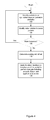
- FIG. 4 is a flowchart showing the operation of one embodiment of the present invention.
- FIG. 5 is an example of a signaling protocol in accordance with one embodiment of the present invention.
- FIG. 6 is an illustration of a domain in the ( ⁇ , ⁇ )-plane, in the shape of a finite convex polygon, in accordance with one embodiment of the present invention.
- Certain aspects of the present invention include process steps and instructions described herein in the form of an algorithm. It should be noted that the process steps and instructions of the present invention could be embodied in software, firmware or hardware, and when embodied in software, could be downloaded to reside on and be operated from different platforms used by a variety of operating systems. The invention can also be in a computer program product which can be executed on a computing system.
- the present invention also relates to an apparatus for performing the operations herein.
- This apparatus may be specially constructed for the purposes, e.g., a specific computer, or it may comprise a general-purpose computer selectively activated or reconfigured by a computer program stored in the computer.
- a computer program may be stored in a computer readable storage medium, such as, but is not limited to, any type of disk including floppy disks, optical disks, CD-ROMs, magnetic-optical disks, read-only memories (ROMs), random access memories (RAMs), EPROMs, EEPROMs, magnetic or optical cards, application specific integrated circuits (ASICs), or any type of media suitable for storing electronic instructions, and each coupled to a computer system bus.
- Memory can include any of the above and/or other devices that can store information/data/programs.
- the computers referred to in the specification may include a single processor or may be architectures employing multiple processor designs for increased computing capability.
- multiple network captures need to be performed by multiple capture agents whose clocks need to be synchronized, e.g., correlated, to a precision necessary to reliably put the network data (e.g., packets, frames etc,) captured by different agents in the correct temporal sequence and to evaluate time delays.
- network data e.g., packets, frames etc,
- data packets and frames are used interchangeably herein although the invention can work with data of various formats and these terms are intended to include all such formats.
- the invention is a system and method for correcting clock discrepancy in simultaneous network traffic data captures.
- the invention uses intrinsic constraints imposed by the nature of the traffic onto the possible temporal sequence of the packets.
- One example is a request packet and its corresponding response packet. If a first trace (data capture at a first position) is closer to a first client then a second trace (data capture at a second position) then the request packet must be seen earlier on the first trace and the response packet must be seen earlier on the second trace.
- a multi-tiered application where a data packet is not seen on all segments (legs), one example of which is where the multi-tiered application involves a first client that requests data from a first server and where the first server requests authentication from an authentication server and only after receiving authentication does the first server send a respond packet to the first client.
- the invention uses the intrinsic restraints of the network architecture and the protocols used at each segment along with the time stamps in the various segments to determine both an offset and scale correction to the clock readings (timestamps) in the traces in order to obtain a correct temporal sequence of packets when using multiple capture agents (engines).
- FIG. 1 is an illustration of a multi-tiered network in accordance with one embodiment of the present invention.
- a conventional Client device 102 can include a processor, memory, storage, applications/programs and is coupled to an Application server 104 .
- the application server 104 can be a conventional server that communicates with the client 102 , authentication server 106 and server 108 , for example. Communication between the devices (client, servers, capture engines/network monitors) on the network illustrated in FIG.
- TCP/IP transmission control protocol
- IP Internet protocol
- TCP/IP protocol suite by B. Forouzan (McGraw-Hill Higher Education 2003) which is incorporated by reference herein in its entirety.
- the capture engines 120 a , 120 b , 120 c capture data transmitted over the communication paths at points 112 a , 112 b and 112 c respectively.
- the capture engines 120 are described in more detail herein.
- FIG. 2 is a block diagram of a capture engine 120 , according to one embodiment of the present invention.
- the capture engine 120 may include, among other components, a processor 204 , memory 206 , a storage module 208 , and an interface 210 , e.g., an interface for communicating with external systems and/or networks, for example.
- Applications are executed using processor 204 and can be received via the interface 210 , stored in memory 206 , stored in a storage device 208 or by using a combination of these elements. In other embodiments, other conventional ways to store and update applications are used.
- applications are stored in the storage device 208 .
- These components are connected and communicate via a bus 202 .
- the capture engine 120 may also include other components such as user input devices (e.g., keyboard and mouse) and display devices (e.g., a display driver card).
- the processor 204 executes computer instructions stored in the memory 206 and/or the storage module 208 . Although only a single processor is illustrated in FIG. 2 , two or more processors may be used to increase the computing capacity and the processing speed of the capture engine 120 . In one embodiment, the processor 204 is embodied as two E5400 Xeon Quad-core processors from Intel Corporation of Santa Clara, Calif.
- the memory 206 is a computer readable storage medium that stores, among other data, computer instruction modules for processing, storing and/or retrieving the network data.
- the memory 206 is a primary storage device (e.g., Random-Access Memory (RAM)) having a faster access speed compared to the storage module 208 .
- the capture engines 120 are able to capture data at the probe points 112 transparently. That is, without significantly affecting the communication between the devices on either end of the communication path.
- the storage module 208 may be a secondary storage device for storing, among others, the raw or processed network data.
- the storage module 208 may be embodied, for example, as a solid-state drive, hard disk or other memory devices capable of storing a large amount of data compared to the memory 206 .
- the network data received at the capture engine 120 are stored and then deleted on a first-in-first-out (FIFO) basis.
- FIFO first-in-first-out
- the interface 210 may include a NIC (network interface card) or other standard network interfaces to receive network data, and to communicate with other network interface devices coupled to a network.
- the interface 210 may be an Ethernet interface, a WiFi (IEEE 802.11) interface, or other types of wired or wireless network interfaces.
- two or more network interfaces may be used to communicate with different types of networks or perform specialized functions.
- the components of the capture engine 120 of FIG. 2 are merely illustrative.
- the storage module 208 may be omitted.
- all the information is stored in the memory 206 .
- the capture engine 120 is embodied as InfiniStream appliance that is available from NetScout Systems of Westford, Mass. Additional details can be found in U.S. Patent application 61/224,764 filed on Jul. 10, 2009 and U.S. patent application Ser. No. 12/703,086 filed on Feb. 9, 2010 entitled “Intelligent Slicing of Monitored Network Packets for Storing” by Nadkarni et al. which are both incorporated by reference herein in their entirety.
- FIG. 4 The operation of one embodiment of the present invention is described in FIG. 4 with reference to the other figures.
- the present invention is used in multi-tier network in which multiple related sessions using multiple protocols can be tracked.
- a problem associated with troubleshooting multi-tier networks involves tracing paths of communication units (referred to as packets herein for ease of description although any type of communication unit can be used) delays and transformations across the network as well as correlating multiple segments (legs) of complex sessions involving multiple interdependent devices, such as client 102 , application server 104 , authentication server 106 and server 108 . Two or more of these devices may be cooperating in servicing a client request.
- Such network captures frequently need to be performed by multiple capture agents, e.g., capture engines 120 a , 120 b , 120 c , whose clocks can not be synchronized (correlated) to the precision needed to reliably put the packets captured by different agents in the correct temporal sequence and evaluate time delays.
- capture agents e.g., capture engines 120 a , 120 b , 120 c , whose clocks can not be synchronized (correlated) to the precision needed to reliably put the packets captured by different agents in the correct temporal sequence and evaluate time delays.
- the present invention is a system and method for correcting clock discrepancy in simultaneous and/or near simultaneous network traffic data captures.
- the invention uses intrinsic constraints imposed by the nature of the traffic onto the possible temporal sequence of the packets.
- a data packet is not seen on all segments (legs) because when a packet is received by a server it terminates the packet and creates a new packet that is sent to another network device. For example, if a packet sent by client 102 and is received by application server 104 , then application server 104 terminates the received packet, strips the appropriate OSI layer header off and creates a new packet having a different header.
- the server 104 receives a request from a client 102 and issues a new request to a downstream server using a different protocol. Therefore packets captured by capture agents (capture engines 120 ) at different segments, e.g., captured at points 112 a , 112 b or 112 c , of the network do not have the same packets, even when the underlying signal or data is the same. Therefore, it is difficult to determine the temporal sequence of packets that are captured in different segments.
- the present invention attempts to solve this problem and in order to do so the present invention needs to be able to synchronize or correlate, i.e., identify the discrepancies between, the clocks in each of the capture agents to properly identify the temporal sequence of packets in a multi-tier, multi-segment network.
- the capture engines 120 a , 120 b , 120 c capture packets at points 112 a , 112 b and 112 c respectively in the network.
- the capture packets can be stored locally and/or sent to the correlation engine 130 .
- FIG. 3 is an illustration of the correlation engine in accordance with one embodiment of the present invention.
- the correlation engine 130 includes a processor 304 , a storage device 308 , memory 304 and applications 312 , that in one embodiment are stored in the storage device 308 and/or memory 306 that are executed by the processor 304 .
- the correlation engine 130 also includes an interface 310 , e.g., an interface for communicating with external systems and/or networks, for example.
- Applications are executed using processor 304 and can be received via the interface 310 , stored in memory 306 , stored in a storage device 308 or a by using a combination of these elements. In other embodiments, other conventional ways to store and update applications are used. For ease of discussion, in the embodiment illustrated in FIG. 3 applications 312 are stored in the storage device 203 . These components are connected and communicate via a bus 302 .
- the capture engine 130 may also include other components such as user input devices (e.g., keyboard and mouse) and display devices (e.g., a display driver card), a display device 320 can be incorporated into the correlation engine 130 or connected thereto.
- Trace data that can be used to determine the clock correction in accordance with the present invention can be stored in a trace file 314 either from previous captured data or can be stored in the storage device 308 or the memory 306 (or some storage device external to the correlation engine 130 , e.g., trace files 140 ) and the data is used by the clock synchronization system 316 , which in this example and for ease of discussion is stored in the storage device although the clock synchronization system 316 can be stored in the memory 306 or external to the correlation engine 130 in manners similar to the applications 312 , for example.
- the processor 304 executes computer instructions stored in the memory 306 and/or the storage module 308 . Although only a single processor is illustrated in FIG. 3 , two or more processors may be used to increase the computing capacity and the processing speed of the correlation engine 130 . In one embodiment, the processor 304 is embodied as two E5400 Xeon Quad-core processors from Intel Corporation of Santa Clara, Calif.
- the memory 306 is a computer readable storage medium that stores, among other data, computer instruction modules for processing, storing and/or retrieving the network data.
- the memory 306 is a primary storage device (e.g., Random-Access Memory (RAM)) having a faster access speed compared to the storage module 308 .
- the correlation engines 130 are able to receive data from the capture engines 120 directly or the data from the capture engines can be stored in trace files 140 , 314 .
- the storage module 308 may be a secondary storage device for storing, among others, the raw or processed network data.
- the storage module 308 may be embodied, for example, as a solid-state drive, hard disk or other memory devices capable of storing a large amount of data compared to the memory 306 .
- the network data received at the correlation engine 130 are stored and then deleted on a first-in-first-out (FIFO) basis.
- FIFO first-in-first-out
- the interface 310 may include a NIC (network interface card) or other standard network interfaces to receive network data, and to communicate with other network interface devices coupled to a network.
- the interface 310 may be an Ethernet interface, a WiFi (IEEE 802.11) interface, or other types of wired or wireless network interfaces.
- two or more network interfaces may be used to communicate with different types of networks or perform specialized functions.
- the components of the correlation engine 130 of FIG. 3 are merely illustrative. In alternative embodiments, the storage module 308 may be omitted, for example.
- the correlation engine 130 identifies 402 packets in an application session. This is accomplished by correlating the packets. Packets are correlated by the correlation engine, for example, that identifies those packets that are part of a single application session. For example, correlating packets can involve analyzing the header information of packets to identify the type of data in the packet. Using this information and combining it with the protocols used between the devices enables the correlation engine 130 to identify the session to which packets belong.
- the correlation engine 130 identifies packets as belonging to a particular session, in the above example, it would be a POP3 email session.
- Examples of the protocols that the correlation engine 130 can use to identify packets in a particular session include: Open Systems Interconnection (OSI) Layer 1 protocols such as ADSL (Asymmetric digital subscriber line), ISDN (Integrated Services Digital Network), PDH (Plesiochronous Digital Hierarchy), T-carrier (T1, T3, etc.), E-carrier (E1, E3, etc.), RS-232 (a serial line interface originally developed to connect modems and computer terminals), SDH (Synchronous Digital Hierarchy), SONET (Synchronous Optical NETworking), Modem standards/ITU V-Series (protocols used to communicate between analog modems over voice telephone lines), ITU-T G.hn Physical Layer.
- OSI Open Systems Interconnection
- Layer 1 protocols such as ADSL (Asymmetric digital subscriber line), ISDN (Integrated Services Digital Network), PDH (Plesiochronous Digital Hierarchy), T-carrier (T1, T3, etc.), E-carrier (E1, E3, etc.), RS-232
- OSI Layer 1/2 protocols such as Ethernet, GFP ITU-T G.7041 (Generic Framing Procedure), OTN ITU-T G.709 (Optical Transport Network also called Optical Channel Wrapper or Digital Wrapper Technology).
- OSI Layer 2 protocols such as: ARCnet (Attached Resource Computer NETwork), CDP (Cisco Discovery Protocol), DCAP (Data Link Switching Client Access Protocol), Dynamic Trunking Protocol, Econet, FDDI (Fiber Distributed Data Interface), Frame Relay, ITU-T G.hn Data Link Layer, HDLC (High Level Data Link Control), IEEE 802.11 (WiFi), IEEE 802.16 (WiMAX), LocalTalk, L2F (Layer 2 Forwarding Protocol), L2TP (Layer 2 Tunneling Protocol), LAPD (Link Access Procedures on the D channel), LLDP (Link Layer Discovery Protocol), LLDP-MED (Link Layer Discovery Protocol-Media Endpoint Discovery), PPP (Point-to-Point Protocol), PPTP (Point-to-Point Tunneling Protocol), Q.710 (Simplified Message Transfer Part), NDP (Neighbor Discovery Protocol), RPR IEEE 802.17 (Resilient Packet Ring), StarLAN, STP (Spanning Tree Protocol), Token ring, VTP VLAN Trun
- OSI Layer 2/3 protocols such as: ATM (Asynchronous Transfer Mode), Frame relay (simplified version of X.25), MPLS (Multi-protocol label switching), X.25, ARP (Address Resolution Protocol), RARP (Reverse Address Resolution Protocol).
- OSI Layer 1/2/3 protocols such as: MTP (Message Transfer Part), NSP (Network Service Part).
- OSI Layer 3 protocols such as: CLNP (Connectionless Networking Protocol), EGP (Exterior Gateway Protocol), EIGRP (Enhanced Interior Gateway Routing Protocol), ICMP (Internet Control Message Protocol), IGMP (Internet Group Management Protocol), IGRP (Interior Gateway Routing Protocol), IPv4 (Internet Protocol version 4), IPv6 (Internet Protocol version 6), IPSec (Internet Protocol Security), IPX (Internetwork Packet Exchange), SCCP (Signaling Connection Control Part), AppleTalk DDP, IS-IS (Intermediate system to intermediate system), OSPF (Open Shortest Path First), BGP (Border Gateway Protocol), RIP (Routing Information Protocol), ICMP (Router Discovery Protocol: Implementation of RFC 1256), GDP (Gateway Discovery Protocol, a Cisco protocol similar to IRDP), HIP (Host Identity Protocol), Xerox Network Systems.
- CLNP Connectionless Networking Protocol
- EGP Exterior Gateway Protocol
- EIGRP Enhanced Interior Gateway Routing Protocol
- ICMP Internet Control Message Protocol
- OSI Layer 4 protocols such as: AHAH (Authentication Header over IP or IPSec), ESPESP (Encapsulating Security Payload over IP or IPSec), GRE (Generic Routing Encapsulation for tunneling), IL (Originally developed as transport layer for 9P), SCTP (Stream Control Transmission Protocol), Sinec H1 (for telecontrol), SPX (Sequenced Packet Exchange), TCP (Transmission Control Protocol), UDP (User Datagram Protocol).
- AHAH Authentication Header over IP or IPSec
- ESPESP Encapsulating Security Payload over IP or IPSec
- GRE Generic Routing Encapsulation for tunneling
- IL Originally developed as transport layer for 9P
- SCTP Stream Control Transmission Protocol
- Sinec H1 for telecontrol
- SPX Sequenced Packet Exchange
- TCP Transmission Control Protocol
- UDP User Datagram Protocol
- OSI Layer 5 protocols such as: 9P (Distributed file system protocol developed originally as part of Plan 9), NCP (NetWare Core Protocol), NFS (Network File System), SMB (Server Message Block), SOCKS (SOCKetS).
- OSI Layer 7 protocols such as: AFP (Apple Filing Protocol), BACnet (Building Automation and Control Network protocol), BitTorrent (A peer-to-peer file sharing protocol), BOOTP (Bootstrap Protocol), Diameter (an authentication, authorization and accounting protocol), DICOM (includes a network protocol definition), DICT (Dictionary protocol), DNS (Domain Name System), DHCP (Dynamic Host Configuration Protocol), ED2K (A peer-to-peer file sharing protocol), FTP (File Transfer Protocol), Finger (which gives user profile information), Gnutella (a peer-to-peer file-swapping protocol), Gopher (a hierarchical hyperlinkable protocol), HTTP (HyperText Transfer Protocol), IMAP (Internet Message Access Protocol), Internet Relay Chat (IRC), ISUP (ISDN User Portion), XMPP (an instant-messaging protocol), LDAP (Lightweight Directory Access Protocol), MIME (Multipurpose Internet Mail Extensions), MSNP (Microsoft Notification Protocol—
- the present invention identifies the temporal sequence of the packets. This can be accomplished in a variety of ways.
- the protocols utilized between various network components e.g., client 102 , application server 104 , authentication server 106 and server 108 are known.
- the invention uses the known relationships between, for example, different setup and communication packets. Since the correlation engine 130 knows the architecture of the system, the protocols between the various network components and the necessary order of various packets within the protocols, the correlation engine 130 is able to infer the temporal order of many of the packets in the application session.
- FIG. 5 is an example of a signaling protocol in accordance with one embodiment of the present invention.
- Packets a, b, c and d are shown as they appear according to uncorrected relative times in traces. From the addressing of the packets, we know that their directions are opposite.
- TCP data ACK and SEQ numbers
- packet d is a response to packet a
- protocol information we can determine that packet b is in response to packet a.
- packet a may be a request packet from client 102 .
- application server 104 Before responding to the request application server 104 needs to authenticate the request and therefore application server 104 sends packet b to authentication server 106 .
- Authentication server 106 uses any conventional authentication procedure and when authentication is complete sends an authentication response packet, e.g., packet c.
- Packets e, f, g and h are examples of packets exchanged between the client 102 and application server 104 , with packet f responsive to packet e and packet h responsive to packet g.
- the time transmitted is known and the time that the packet is captured by the capture engine 120 is known according to the clock in the corresponding capture engine.
- the clocks on the various network devices and capture engines 120 are not precisely synchronized. Due to differences in clocks in different capture engines 120 and network devices, clock discrepancies exist. There are two sources of errors in such clocks (1) offsets and (2) clock skew (scale).
- the offset error is the absolute difference in two clocks at a particular time and the skew (scaling) error is the rate at which the difference changes.
- the correlation engine determines 406 whether packets from different sessions have been received or are part of the trace files 314 , 140 . If additional sessions are present the process continues with another session at step 402 .
- the clock synchronization module 316 determines 410 the scaling and offset corrections to the clocks of the capture engines 120 .
- the clock synchronization module 316 operates in a multi-segment, multi-session environment and analyzes situations where more than one trace is taken at different locations by the capture engines 120 in a network and identifies instances of the same packets as seen in different traces.
- absolute times are assigned to packet instances. For ease of discussion this term is used to denote a packet as seen by a particular capture engine 120 , as opposed to an abstract notion of a packet travelling over the network from source to destination while keeping its identity.
- the capture engines 120 assign times, absolute or relative, e.g., time since capture start, to packets according to each capture engine's 120 hardware clock. However clocks on different capture engines 120 are not exactly synchronized.
- clock speeds in the capture engines 120 may vary slightly to introduce scaling (skew) errors. Even slight variation however is significant compared to millisecond- and submillisecond-range delays between instances of a packet. Using relative times without regard to these clock discrepancies leads to the effect where a packet can be seen downstream before it is seen at an upstream location or a packet appears on one leg with a timestamp earlier than another packet from another leg that must have preceded it, which is unacceptable from the point of view of usability and accuracy.
- skew scaling
- the present invention solves this problem by correcting clock discrepancies in order to correct trace timings (synchronize traces) so that no packet goes (apparently) “back in time,” i.e., the present invention presents the situation where the effect does not precede the cause (e.g., a reply does not precede its request).
- the clock synchronization algorithm 316 works on a pair of traces, where instances of the same packet have already been identified.
- packet a is received by capture engine 120 a at point 112 a at time T 1k .
- Packet b in this example is correlated to packet a, e.g., packet b is an authentication request that is sent in response to receiving packet a.
- packet b is received by capture engine 120 b at point 112 b at time T 1n , which is prior to T 1k .
- the cause of this is a discrepancy between the clocks in client 102 and application server 104 .
- the present invention adjusts for errors in the offset ( ⁇ ) and the scaling coefficient ( ⁇ ) as shown below.
- the present invention then applies correction factor (T) for each timestamp on one of the devices, e.g., client 102 or application server 104 in this example. T ⁇ T+ ⁇
- This equation is determined with parameters ⁇ and ⁇ being constants for a particular pair of capture engines 120 or network devices (common for all packets) and are to be determined with the condition that no packet can precede another packet that must have occurred earlier.
- Equations (1) and (2) represent the condition that no packet can precede another packet that must have occurred earlier.
- the present invention can, but does not need to, know all the solutions to the problem, one is sufficient, especially if it does not lie on the boundary of the polygon.
- the present invention proceeds to determine two diametrically opposite points on the boundary of the solution domain, and can take any point between them, e.g., a point substantially in the middle, as the close-to-optimal solution (this point lies in the solution domain due to its convexity).
- inequalities (1, 2) yield inequalities for ⁇ only by elimination of ⁇ as shown in equations (5) or (6), T 1k T 2n ⁇ T 2n > ⁇ >T 1n T 2k ⁇ T 2k , that is:
- the clock synchronization module 316 determines the pairs (n, k) that define the strictest bounds for ⁇ , i.e., the greatest lower bound in (5) and smallest higher bound in (6). These, with corresponding values for a, define the sought-for points on the boundary of the solution domain. Alternatively, the clock synchronization module 316 can determine the strictest bounds for ⁇ , and take corresponding values for ⁇ . That would provide, possibly, a different solution.
- FIG. 6 is an illustration of a domain in the ( ⁇ , ⁇ )-plane, in the shape of a finite convex polygon, in accordance with one embodiment of the present invention.
- Each line represents an inequality, with arrows pointing to the correct half-plane.
- the solution domain, the intersection of all half-planes, is represented by a hashed polygon 602 .
- the clock synchronization module 316 performs the following steps:
- the rightmost corner of the solution domain can be found in the same way.
- a scaling and offset value within the allowable range 602 is used, and is applied 420 to adjust the timelines or timestamps of the packet to perform analysis including network delays and application latencies.
- the present invention corrects clock discrepancy in simultaneous network traffic data captures.
- T time correction value
- the invention uses intrinsic constraints imposed by the nature of the traffic onto the possible temporal sequence of the packets.
- One example is a request packet and its corresponding response packet. If a first trace (position of data capture) is closer to a first client then a second trace then the request packet must be seen earlier on the first trace and the response packet must be seen earlier on the second trace.
- the multi-tiered application involves a first client that requests data from a first server and where the first server requests authentication from an authentication server and only after receiving authentication does the first server send a respond packet to the first client.
- the invention uses the intrinsic restraints of the network architecture and the protocols used at each segment along with the time stamps in the various segments to determine both an offset and scale correction to the clock readings (timestamps) in the traces in order to obtain a correct temporal sequence of packets when using multiple capture agents (engines).
Abstract
Description
T→αT+τ
T 1k <α·T 2k+τ (1)
T 1n >α·T 2n+τ (2)
T 1n −α·T 2n <τ<T 1k −α·T 2k
T 1k T 2n −τT 2n >α>T 1n T 2k −τT 2k, that is:
-
- 1. select an arbitrary line (say, line a in
FIG. 6 ) - 2. if the line defines the upper half-plane, find all its intersections with lower-half-plane lines, and vice versa
- 3. select the rightmost intersection point and the corresponding line (line b in
FIG. 6 ) - 4. with this new line, repeat step 2, unless line b already was selected right before a, in which case the solution is found
- 1. select an arbitrary line (say, line a in
Claims (6)
Priority Applications (1)
| Application Number | Priority Date | Filing Date | Title |
|---|---|---|---|
| US12/716,987 US9602366B1 (en) | 2010-03-03 | 2010-03-03 | System and method for correcting clock discrepancy in simultaneous network traffic captures |
Applications Claiming Priority (1)
| Application Number | Priority Date | Filing Date | Title |
|---|---|---|---|
| US12/716,987 US9602366B1 (en) | 2010-03-03 | 2010-03-03 | System and method for correcting clock discrepancy in simultaneous network traffic captures |
Publications (1)
| Publication Number | Publication Date |
|---|---|
| US9602366B1 true US9602366B1 (en) | 2017-03-21 |
Family
ID=58337261
Family Applications (1)
| Application Number | Title | Priority Date | Filing Date |
|---|---|---|---|
| US12/716,987 Active 2032-09-14 US9602366B1 (en) | 2010-03-03 | 2010-03-03 | System and method for correcting clock discrepancy in simultaneous network traffic captures |
Country Status (1)
| Country | Link |
|---|---|
| US (1) | US9602366B1 (en) |
Cited By (5)
| Publication number | Priority date | Publication date | Assignee | Title |
|---|---|---|---|---|
| WO2018175342A1 (en) * | 2017-03-24 | 2018-09-27 | Parrable Inc. | Timestamp-based session association |
| CN110266420A (en) * | 2019-04-29 | 2019-09-20 | 北京达佳互联信息技术有限公司 | Clock synchronizing method, clock synchronization apparatus and computer readable storage medium |
| US10491451B2 (en) | 2015-05-19 | 2019-11-26 | Parrable Inc. | Timestamp-based matching of identifiers |
| US10785043B2 (en) * | 2019-02-01 | 2020-09-22 | State Grid Jiangsu Electric Power Co., Ltd. | Load shedding system, communication method and access apparatus thereof |
| US11799713B2 (en) | 2015-09-22 | 2023-10-24 | Parrable Inc. | Timestamp-based association of identifiers |
Citations (9)
| Publication number | Priority date | Publication date | Assignee | Title |
|---|---|---|---|---|
| US6327274B1 (en) * | 1998-09-15 | 2001-12-04 | Nokia Telecommunications, Inc. | Method for estimating relative skew between clocks in packet networks |
| US6335931B1 (en) * | 1998-05-29 | 2002-01-01 | Finisar Corporation | System for synchronizing network data transmission and collection |
| US20020143998A1 (en) * | 2001-03-30 | 2002-10-03 | Priya Rajagopal | Method and apparatus for high accuracy distributed time synchronization using processor tick counters |
| US20040068583A1 (en) * | 2002-10-08 | 2004-04-08 | Monroe David A. | Enhanced apparatus and method for collecting, distributing and archiving high resolution images |
| US20050018694A1 (en) * | 2003-07-04 | 2005-01-27 | International Business Machines Corporation | Method for analyzing network trace, method for judging order among nodes, processor for analyzing network trace, computer-executable program for controlling computer as processor, and method for correcting time difference among nodes in network |
| US20060265430A1 (en) * | 1995-09-29 | 2006-11-23 | Manin Dmitrii Y | Transactions matching for multi-tier architectures |
| US20090184871A1 (en) * | 2008-01-23 | 2009-07-23 | Mostafa Tofighbakhsh | GPS with time integrated call initiation |
| US7865760B2 (en) * | 2005-09-09 | 2011-01-04 | International Business Machines Corporation | Use of T4 timestamps to calculate clock offset and skew |
| US8055612B2 (en) * | 2003-09-03 | 2011-11-08 | Hyperformix, Inc. | System and method for aligning data frames in time |
-
2010
- 2010-03-03 US US12/716,987 patent/US9602366B1/en active Active
Patent Citations (9)
| Publication number | Priority date | Publication date | Assignee | Title |
|---|---|---|---|---|
| US20060265430A1 (en) * | 1995-09-29 | 2006-11-23 | Manin Dmitrii Y | Transactions matching for multi-tier architectures |
| US6335931B1 (en) * | 1998-05-29 | 2002-01-01 | Finisar Corporation | System for synchronizing network data transmission and collection |
| US6327274B1 (en) * | 1998-09-15 | 2001-12-04 | Nokia Telecommunications, Inc. | Method for estimating relative skew between clocks in packet networks |
| US20020143998A1 (en) * | 2001-03-30 | 2002-10-03 | Priya Rajagopal | Method and apparatus for high accuracy distributed time synchronization using processor tick counters |
| US20040068583A1 (en) * | 2002-10-08 | 2004-04-08 | Monroe David A. | Enhanced apparatus and method for collecting, distributing and archiving high resolution images |
| US20050018694A1 (en) * | 2003-07-04 | 2005-01-27 | International Business Machines Corporation | Method for analyzing network trace, method for judging order among nodes, processor for analyzing network trace, computer-executable program for controlling computer as processor, and method for correcting time difference among nodes in network |
| US8055612B2 (en) * | 2003-09-03 | 2011-11-08 | Hyperformix, Inc. | System and method for aligning data frames in time |
| US7865760B2 (en) * | 2005-09-09 | 2011-01-04 | International Business Machines Corporation | Use of T4 timestamps to calculate clock offset and skew |
| US20090184871A1 (en) * | 2008-01-23 | 2009-07-23 | Mostafa Tofighbakhsh | GPS with time integrated call initiation |
Cited By (8)
| Publication number | Priority date | Publication date | Assignee | Title |
|---|---|---|---|---|
| US10491451B2 (en) | 2015-05-19 | 2019-11-26 | Parrable Inc. | Timestamp-based matching of identifiers |
| US11799713B2 (en) | 2015-09-22 | 2023-10-24 | Parrable Inc. | Timestamp-based association of identifiers |
| WO2018175342A1 (en) * | 2017-03-24 | 2018-09-27 | Parrable Inc. | Timestamp-based session association |
| US10715413B2 (en) | 2017-03-24 | 2020-07-14 | Parrable Inc. | Timestamp-based session association |
| EP3602970A4 (en) * | 2017-03-24 | 2021-01-06 | Parrable Inc. | Timestamp-based session association |
| US10785043B2 (en) * | 2019-02-01 | 2020-09-22 | State Grid Jiangsu Electric Power Co., Ltd. | Load shedding system, communication method and access apparatus thereof |
| CN110266420A (en) * | 2019-04-29 | 2019-09-20 | 北京达佳互联信息技术有限公司 | Clock synchronizing method, clock synchronization apparatus and computer readable storage medium |
| CN110266420B (en) * | 2019-04-29 | 2021-02-12 | 北京达佳互联信息技术有限公司 | Clock synchronization method, clock synchronization apparatus, and computer-readable storage medium |
Similar Documents
| Publication | Publication Date | Title |
|---|---|---|
| US11876695B2 (en) | Path monitoring system (PMS) controller or ingress node based multiprotocal label switching (MPLS) ping and traceroute in inter-autonomous system (AS) segment routing (SR) networks | |
| US9729348B2 (en) | Tunnel-in-tunnel source address correction | |
| US10826809B2 (en) | Multi-hop reflector sessions | |
| EP3216143B1 (en) | Transmitting residence time information in a network | |
| US8374095B2 (en) | Connection verification for MPLS label switched paths and pseudowires | |
| US9450846B1 (en) | System and method for tracking packets in a network environment | |
| EP2865135B1 (en) | Determining the network topology of a communication network | |
| US9602366B1 (en) | System and method for correcting clock discrepancy in simultaneous network traffic captures | |
| US20130191628A1 (en) | Media Path Monitoring Over a Secure Network | |
| EP2509261A1 (en) | Monitoring of a network element in a packet-switched network | |
| US8971195B2 (en) | Querying health of full-meshed forwarding planes | |
| US20180026862A1 (en) | Estimation device, estimation method, and recording medium | |
| EP3157211B1 (en) | Isis-based flooding method and device | |
| US11336569B2 (en) | Ping and traceroute in inter-autonomous system (AS) segment routing (SR) networks without requiring headend router or path monitoring system (PMS) controller knowledge of topology outside of origin as | |
| EP4017089A2 (en) | Network policy application based on session state | |
| US20210044678A1 (en) | Optimized quic fallback on access networks and endpoints | |
| CN112910704B (en) | Local area network system, method and device supporting dynamic self-adaptive network configuration | |
| Lebrun | Reaping the benefits of ipv6 segment routing | |
| JP2020188478A (en) | Method for synchronizing topology information in sfc network, and routing network element | |
| Cohen | Source attribution for network address translated forensic captures | |
| US8699376B2 (en) | Method and system for de-synchronizing link state message refreshes | |
| KR102489541B1 (en) | Trip time estimation for transmission control protocol | |
| Cisco | Commands: debug serial interface through debug tacacs events | |
| Kuri et al. | Performance Measurement of IoT Traffic Through SRv6 Network Programming | |
| Tripathi et al. | Ensuring reliability in cloud computing and comparison on IPv6 encouraged with protocols |
Legal Events
| Date | Code | Title | Description |
|---|---|---|---|
| AS | Assignment |
Owner name: NETSCOUT SYSTEMS, INC., MASSACHUSETTS Free format text: ASSIGNMENT OF ASSIGNORS INTEREST;ASSIGNOR:MANIN, DMITRII YURIEVICH;REEL/FRAME:024030/0050 Effective date: 20100302 |
|
| AS | Assignment |
Owner name: JPMORGAN CHASE BANK, N.A., NEW YORK Free format text: SECURITY INTEREST;ASSIGNORS:NETSCOUT SYSTEMS, INC.;FIDELIA TECHNOLOGY, INC.;NETSCOUT SERVICE LEVEL CORPORATION;AND OTHERS;REEL/FRAME:036087/0808 Effective date: 20150714 Owner name: NETSCOUT SYSTEMS, INC., MASSACHUSETTS Free format text: RELEASE BY SECURED PARTY;ASSIGNOR:KEYBANK NATIONAL ASSOCIATION;REEL/FRAME:036087/0702 Effective date: 20150714 |
|
| STCF | Information on status: patent grant |
Free format text: PATENTED CASE |
|
| MAFP | Maintenance fee payment |
Free format text: PAYMENT OF MAINTENANCE FEE, 4TH YEAR, LARGE ENTITY (ORIGINAL EVENT CODE: M1551); ENTITY STATUS OF PATENT OWNER: LARGE ENTITY Year of fee payment: 4 |