US9601981B2 - Linear actuator - Google Patents
Linear actuator Download PDFInfo
- Publication number
- US9601981B2 US9601981B2 US14/375,133 US201314375133A US9601981B2 US 9601981 B2 US9601981 B2 US 9601981B2 US 201314375133 A US201314375133 A US 201314375133A US 9601981 B2 US9601981 B2 US 9601981B2
- Authority
- US
- United States
- Prior art keywords
- tube
- linear actuator
- stopper
- rod
- fully extended
- Prior art date
- Legal status (The legal status is an assumption and is not a legal conclusion. Google has not performed a legal analysis and makes no representation as to the accuracy of the status listed.)
- Expired - Fee Related, expires
Links
Images


Classifications
-
- H—ELECTRICITY
- H02—GENERATION; CONVERSION OR DISTRIBUTION OF ELECTRIC POWER
- H02K—DYNAMO-ELECTRIC MACHINES
- H02K33/00—Motors with reciprocating, oscillating or vibrating magnet, armature or coil system
-
- H—ELECTRICITY
- H02—GENERATION; CONVERSION OR DISTRIBUTION OF ELECTRIC POWER
- H02K—DYNAMO-ELECTRIC MACHINES
- H02K41/00—Propulsion systems in which a rigid body is moved along a path due to dynamo-electric interaction between the body and a magnetic field travelling along the path
- H02K41/02—Linear motors; Sectional motors
- H02K41/03—Synchronous motors; Motors moving step by step; Reluctance motors
- H02K41/031—Synchronous motors; Motors moving step by step; Reluctance motors of the permanent magnet type
-
- H—ELECTRICITY
- H02—GENERATION; CONVERSION OR DISTRIBUTION OF ELECTRIC POWER
- H02K—DYNAMO-ELECTRIC MACHINES
- H02K7/00—Arrangements for handling mechanical energy structurally associated with dynamo-electric machines, e.g. structural association with mechanical driving motors or auxiliary dynamo-electric machines
- H02K7/08—Structural association with bearings
-
- H—ELECTRICITY
- H02—GENERATION; CONVERSION OR DISTRIBUTION OF ELECTRIC POWER
- H02K—DYNAMO-ELECTRIC MACHINES
- H02K7/00—Arrangements for handling mechanical energy structurally associated with dynamo-electric machines, e.g. structural association with mechanical driving motors or auxiliary dynamo-electric machines
- H02K7/10—Structural association with clutches, brakes, gears, pulleys or mechanical starters
- H02K7/102—Structural association with clutches, brakes, gears, pulleys or mechanical starters with friction brakes
Definitions
- the present invention relates to a linear actuator that is extended/contracted in the axial direction by an electromagnetic force.
- JP2005-106242A discloses a linear actuator in which a first tube and a second tube are relatively displaced in the axial direction by an electromagnetic force generated between permanent magnets provided in the first tube and coils provided in the second tube.
- the linear actuator described in JP2005-106242A includes a shaft with fixed permanent magnets, and in a fully extended state, the shaft is subjected to a compression load due to self thrust. Therefore, the distortion of the shaft is easily propagated to the permanent magnets, and the permanent magnets may be damaged.
- An object of the present invention is to prevent a permanent magnet from being damaged due to self thrust in a linear actuator that is in a fully extended state.
- a linear actuator that is configured to be extended/contracted by relatively displacing a first tube and a second tube in an axial direction, includes a rod that is provided inside the first tube, a plurality of permanent magnets that are held in the rod so as to be arranged in the axial direction; a stopper that is provided on a tip-end portion of the rod, a coil that is provided inside the second tube so as to face the permanent magnets, and a stopper receiving portion that is provided on the second tube so as to face the stopper, wherein the relative displacement between the first tube and the second tube in the extension direction is restricted by bringing an extension-direction-side end surface of the stopper into contact with the stopper receiving portion at a fully extended position.
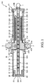
- FIG. 1 is an axial cross section of a linear actuator according to an embodiment of the present invention and is a diagram showing the linear actuator in a fully contracted state.
- FIG. 2 is an axial cross section of linear actuator according to the embodiment of the present invention and is a diagram showing the linear actuator in a fully extended state.
- a linear actuator 100 according to an embodiment of the present invention will be described with reference to FIGS. 1 and 2 .
- the linear actuator 100 is used as a vibration control actuator for suppressing vibration in, for example, automobiles, railroad vehicles, buildings, and so forth.
- the linear actuator 100 includes a first tube 10 , a second tube 20 that is slidably inserted into the first tube 10 , a rod 30 that is fixed at the end portion of the first tube 10 and that holds permanent magnets 31 , and a coil holder 40 that is provided so as to be fitted with the inside of the second tube 20 and that holds coils 41 facing the permanent magnets 31 .
- the linear actuator 100 is disposed between two members, which are relatively moved to each other, via a connecting portion 1 provided on the first tube 10 and connecting shafts 2 provided on the second tube 20 .
- a thrust (electromagnetic force) that drives the rod 30 in the axial direction is generated in accordance with the current flowing through the coils 41 , and the first tube 10 and the second tube 20 are relatively displaced on the basis of the thrust.
- the linear actuator 100 extends/contracts between a fully contracted position shown in FIG. 1 and a fully extended position shown in FIG. 2 .
- the first tube 10 includes a cylindrical outer tube 11 having openings at both ends and a cap 12 that is connected at one end of the outer tube 11 .
- the one end of the first tube 10 is closed by the cap 12 and the other end of the first tube 10 is formed as an open end.
- the connecting portion 1 is fixed on the outer-side surface of the cap 12 .
- the second tube 20 includes a cylindrical base portion 21 , an inner tube 22 that is fixed at the one end side of the base portion 21 , and a guide tube 23 that is fixed at the other end side of the base portion 21 .
- the base portion 21 is a tubular member having openings at both ends.
- a pair of connecting shafts 2 projecting in the radial directions are fixed on the outer circumference of the base portion 21 . These connecting shafts 2 are provided at positions opposite to each other.
- the second tube 20 is connected via the connecting shafts 2 to the one of the two members, which are relatively moved to each other, and the first tube 10 is connected via the connecting portion 1 to the other of the two members, which are relatively moved.
- the outer tube 11 and the inner tube 22 are tubular members having openings at both ends.
- the inner tube 22 is slidably inserted into the outer tube 11 in a state in which it is provided on the base portion 21 .
- the one end of the inner tube 22 is fitted with and fixed to an inner circumferential surface 21 A of the base portion 21 , and thereby the inner tube 22 is supported at the one end thereof by the base portion 21 .
- the outer circumference of the inner tube 22 is slidably fitted with the inner circumference of the outer tube 11 , and thus both tubes are supported in a relatively displaceable manner.
- a first bearing 13 that is in sliding contact with an outer circumferential surface 22 A of the inner tube 22 is provided on the inner circumference of the open end of the outer tube 11 into which the inner tube 22 is inserted.
- a second bearing 24 that is in sliding contact with an inner circumferential surface 11 A of the outer tube 11 is provided on the outer circumference of the free end of the inner tube 22 .
- the first bearing 13 and the second bearing 24 are annular slide materials.
- the guide tube 23 is a tubular member having openings at both ends.
- a stopper 50 that is fixed to a tip-end portion 30 C of the rod 30 is slidably fitted with the inner circumference of the guide tube 23 . With such a configuration, the tip-end portion 30 C of the rod 30 is prevented from swinging in the radial direction.
- the rod 30 is a rod-shaped member having a hollow portion 30 A.
- a base-end portion 30 B of the rod 30 is fixed to the cap 12 forming the end portion of the first tube 10 .
- the stopper 50 mentioned above is fixed to the tip-end portion 30 C of the rod 30 .
- a plurality of permanent magnets 31 are held so as to be arranged along the axial direction.
- the permanent magnets 31 are formed to have a columnar shape and are magnetized to exhibit N poles and S poles in the axial direction.
- Adjacent permanent magnets 31 are arranged such that the same magnetic poles are faced to each other.
- yokes 32 are provided between the adjacent permanent magnets 31 .
- the yokes 32 may not necessarily be provided, and respective permanent magnets 31 may be arranged so as to be directly adjacent to each other.
- the coil holder 40 is a tubular member having a large-diameter portion 42 and a small-diameter portion 43 .
- the large-diameter portion 42 is formed to have the outer diameter larger than that of the small-diameter portion 43 .
- An outer circumferential surface 42 A of the large-diameter portion 42 is fitted with and fixed to an inner circumferential surface 21 B of the base portion 21 , and thereby the coil holder 40 is supported at the one end thereof by the base portion 21 .
- the inner circumferential surface 21 B of the base portion 21 is formed to have the inner diameter larger than that of the inner circumferential surface 21 A of the base portion 21 .
- An annular gap 8 is formed around the coil holder 40 .
- the annular gap 8 is formed between an inner circumferential surface 22 B of the inner tube 22 and an outer circumferential surface 43 B of the small-diameter portion 43 of the coil holder 40 .
- the configuration is not limited to that mentioned above, and a configuration in which the annular gap 8 is not formed and the inner circumferential surface 22 B of the inner tube 22 is provided so as to be fitted with the outer circumferential surface 43 B of the small-diameter portion 43 of the coil holder 40 without a gap therebetween is also possible.
- the coil holder 40 has an insertion hole 44 through which the rod 30 is inserted in the axial direction.
- An annular depressed portion 43 A is formed on the inner circumferential surface of the small-diameter portion 43 forming the insertion hole 44 , and a plurality of coils 41 are fixed in the annular depressed portion 43 A.
- the plurality of coils 41 are disposed side-by-side along the axial direction so as to face the permanent magnets 31 .
- the current supplied to the coils 41 is controlled by a controller (not shown), which is installed, for example, outside the linear actuator 100 .
- the controller controls the magnitude and the direction of the current that is supplied to the coils 41 on the basis of relative positional-information of the coils 41 and the permanent magnets 31 detected by a position detector 9 . By doing so, the level and the direction (extension/contraction direction) of the thrust generated by the linear actuator 100 are adjusted.
- the position detector 9 is a Hall element that generates the Hall voltage corresponding to the strength of the magnetic field and is embedded into the inner side of the large-diameter portion 42 of the coil holder 40 .
- the linear actuator 100 when the current is supplied to the coils 41 in a predetermined direction, the thrust driving the rod 30 leftward in FIG. 2 is generated, the outer tube 11 is moved leftward while in sliding contact with the inner tube 22 , and the linear actuator 100 is contracted.
- the open end of the outer tube 11 When the linear actuator 100 is contracted to the fully contracted position (see FIG. 1 ), the open end of the outer tube 11 is brought into contact with the right end portion of the base portion 21 , thereby restricting further movement of the rod 30 . In this way, the open end of the outer tube 11 functions as a restricting portion that restricts the amount of contraction of the linear actuator 100 .
- a protruding portion 23 A that protrudes inward is formed, and the left-side surface of the protruding portion 23 A is provided as the stopper receiving portion 23 B that faces the stopper 50 .
- the stopper 50 has a disk-like guide portion 51 and a cylindrical stroke defining portion 52 that extends in the axial direction from the guide portion 51 .
- the center portion of the disk-like guide portion 51 is fixed to the tip-end portion 30 C of the rod 30 .
- the outer circumference of the guide portion 51 is slidably fitted with the inner circumference of the guide tube 23 .
- a plurality of through holes 53 that penetrate through the guide portion 51 in the axial direction are formed in the guide portion 51 .
- the through holes 53 communicate a second chamber 62 and a third chamber 63 that are partitioned by the guide portion 51 in the guide tube 23 .
- the air inside the linear actuator 100 travels between a first chamber 61 and the second chamber 62 through the insertion hole 44 of the coil holder 40 .
- external air travels into and out of the second chamber 62 through the through holes 53 of the guide portion 51 from the third chamber 63 , thereby reducing the air resistance exerted on the stopper 50 .
- the stroke defining portion 52 is formed to have a cylindrical shape extending in the axial direction along the rod 30 and has an extension-direction-side end surface 52 A at its tip end.
- the extension-direction-side end surface 52 A is directed toward a tip-end portion 30 B of the rod 30 and faces the stopper receiving portion 23 B.
- the length of the stroke defining portion 52 in the axial direction is arbitrarily set such that the extension-direction-side end surface 52 A of the stroke defining portion 52 is positioned at the side of a permanent magnet 31 A that is disposed at the left end.
- the shape of the stopper 50 is not limited to the configuration mentioned above, and, for example, the stroke defining portion 52 may be formed of a columnar pin extending in the axial direction from the guide portion 51 .
- the extension-direction-side end surface 52 A of the stroke defining portion 52 is brought into contact with the stopper receiving portion 23 B to restrict the movement of the rod 30 at the position in which the tip-end portion 30 C of the rod 30 is projected by a predetermined length with respect to the stopper receiving portion 23 B, and thereby, the positions of the permanent magnets 31 and the coils 41 at the fully extended position are defined.
- the permanent magnet 31 A which is disposed at the left end among the plurality of permanent magnets 31 arranged in the axial direction of the rod 30 , projects with respect to the stopper receiving portion 23 B in the opposite direction (left direction in FIG. 2 ) from the side where the coils 41 are provided. Because the permanent magnet 31 A disposed at the left end is positioned within the region under the effect of the electromagnetic force of the coils 41 at the fully extended position in this way, the level of the thrust generated in the linear actuator 100 near the fully extended position is sufficiently ensured. In addition, because the permanent magnet 31 A disposed at the left end moves so as to face the position detector 9 near the fully extended position, the position detector 9 can accurately detect the relative position of the rod 30 by the magnetic field generated at the permanent magnet 31 A disposed at the left end.
- the linear actuator 100 because the extension-direction-side end surface 52 A of the stopper 50 is brought into contact with the stopper receiving portion 23 B at the fully extended position and the rod 30 is pulled in the axial direction, the relative displacement of the first tube 10 and the second tube 20 in the extension direction is restricted. Therefore, because the rod 30 is subjected to a tensile load due to the self thrust in the fully extended state, it is possible to suppress the distortion of the rod 30 compared with the conventional configuration that undergoes deformation, such as buckling, and to prevent the permanent magnets 31 from being damaged.
- the stopper 50 has the stroke defining portion 52 extending from the tip-end portion 30 C of the rod 30 toward the base-end portion 30 B of the rod 30 and the extension-direction-side end surface 52 A of the stroke defining portion 52 is brought into contact with the stopper receiving portion 23 B at the fully extended position, the positions of the permanent magnets 31 and the coils 41 at the fully extended position are defined. Therefore, the permanent magnets 31 are appropriately positioned, and the level of the thrust generated near the fully extended position is sufficiently ensured.
- the second tube 20 includes the guide tube 23 in which the inner circumference thereof is slidably fitted with the outer circumference of the guide portion 51 of the stopper 50 . Therefore, because the stopper 50 is in sliding contact with the inner circumference of the second tube 20 during extension/contraction, the tip-end portion 30 C of the rod 30 is prevented from swinging in the radial direction.
- the through holes 53 are provided on the stopper 50 , and thereby, two spaces (the second chamber 62 and the third chamber 63 ) partitioned by the stopper 50 in the guide tube 23 are communicated through the through holes 53 . Therefore, the air travels between the two spaces through the through holes 53 during extension/contraction, thereby reducing the air resistance exerted on the stopper 50 .
Landscapes
- Engineering & Computer Science (AREA)
- Power Engineering (AREA)
- Physics & Mathematics (AREA)
- Chemical & Material Sciences (AREA)
- Combustion & Propulsion (AREA)
- Electromagnetism (AREA)
- Linear Motors (AREA)
Abstract
Description
Claims (5)
Applications Claiming Priority (3)
| Application Number | Priority Date | Filing Date | Title |
|---|---|---|---|
| JP2012-164710 | 2012-07-25 | ||
| JP2012164710A JP5933379B2 (en) | 2012-07-25 | 2012-07-25 | Linear actuator |
| PCT/JP2013/069082 WO2014017311A1 (en) | 2012-07-25 | 2013-07-12 | Linear actuator |
Publications (2)
| Publication Number | Publication Date |
|---|---|
| US20150015090A1 US20150015090A1 (en) | 2015-01-15 |
| US9601981B2 true US9601981B2 (en) | 2017-03-21 |
Family
ID=49997127
Family Applications (1)
| Application Number | Title | Priority Date | Filing Date |
|---|---|---|---|
| US14/375,133 Expired - Fee Related US9601981B2 (en) | 2012-07-25 | 2013-07-12 | Linear actuator |
Country Status (4)
| Country | Link |
|---|---|
| US (1) | US9601981B2 (en) |
| EP (1) | EP2797214B1 (en) |
| JP (1) | JP5933379B2 (en) |
| WO (1) | WO2014017311A1 (en) |
Families Citing this family (5)
| Publication number | Priority date | Publication date | Assignee | Title |
|---|---|---|---|---|
| JP6364317B2 (en) * | 2014-10-29 | 2018-07-25 | Kyb株式会社 | Linear actuator |
| JP5948390B2 (en) * | 2014-10-29 | 2016-07-06 | Kyb株式会社 | Linear actuator |
| JP6585894B2 (en) * | 2014-10-29 | 2019-10-02 | Kyb株式会社 | Linear actuator |
| KR101968481B1 (en) * | 2017-11-21 | 2019-04-15 | (주)이미지스테크놀로지 | Impact type vibration actuator |
| GB2576004B (en) * | 2018-07-31 | 2022-10-05 | Trw Ltd | An electromagnetic linear actuator |
Citations (12)
| Publication number | Priority date | Publication date | Assignee | Title |
|---|---|---|---|---|
| JP2005106242A (en) | 2003-10-01 | 2005-04-21 | Kawasaki Heavy Ind Ltd | Electromagnetic actuator for vibration control |
| US20060181158A1 (en) * | 2004-12-27 | 2006-08-17 | Hitachi, Ltd. | Cylindrical linear motor, electromagnetic suspension, and vehicle using the same |
| JP2007274820A (en) | 2006-03-31 | 2007-10-18 | Hitachi Ltd | Linear motor |
| US20080079522A1 (en) * | 2006-09-28 | 2008-04-03 | Murata Machinery, Ltd. | Linear motor and machine tool having the same mounted thereon |
| JP2008236832A (en) | 2007-03-16 | 2008-10-02 | Hitachi Ltd | Tubular linear motor |
| WO2009039865A1 (en) | 2007-09-20 | 2009-04-02 | Festo Ag & Co. Kg | Electrical direct linear drive device having two guide rails for the linear guidance of a stator having a driven sled |
| JP2010130805A (en) | 2008-11-28 | 2010-06-10 | Kayaba Ind Co Ltd | Linear actuator |
| US7825548B2 (en) * | 2005-10-21 | 2010-11-02 | Kabushiki Kaisha Yaskawa Denki | Cylindrical linear motor |
| JP2011193641A (en) | 2010-03-15 | 2011-09-29 | Koganei Corp | Linear motor and method for manufacturing reciprocating rod |
| WO2012035989A1 (en) | 2010-09-16 | 2012-03-22 | カヤバ工業株式会社 | Linear actuator |
| WO2012039293A1 (en) | 2010-09-21 | 2012-03-29 | カヤバ工業株式会社 | Linear actuator |
| US9035732B2 (en) * | 2012-06-19 | 2015-05-19 | Kayaba Industry Co., Ltd. | Linear actuator and groove fashioning method for linear actuator |
-
2012
- 2012-07-25 JP JP2012164710A patent/JP5933379B2/en active Active
-
2013
- 2013-07-12 US US14/375,133 patent/US9601981B2/en not_active Expired - Fee Related
- 2013-07-12 WO PCT/JP2013/069082 patent/WO2014017311A1/en not_active Ceased
- 2013-07-12 EP EP13823390.3A patent/EP2797214B1/en not_active Not-in-force
Patent Citations (15)
| Publication number | Priority date | Publication date | Assignee | Title |
|---|---|---|---|---|
| JP2005106242A (en) | 2003-10-01 | 2005-04-21 | Kawasaki Heavy Ind Ltd | Electromagnetic actuator for vibration control |
| US20060181158A1 (en) * | 2004-12-27 | 2006-08-17 | Hitachi, Ltd. | Cylindrical linear motor, electromagnetic suspension, and vehicle using the same |
| US7825548B2 (en) * | 2005-10-21 | 2010-11-02 | Kabushiki Kaisha Yaskawa Denki | Cylindrical linear motor |
| JP2007274820A (en) | 2006-03-31 | 2007-10-18 | Hitachi Ltd | Linear motor |
| US20080079522A1 (en) * | 2006-09-28 | 2008-04-03 | Murata Machinery, Ltd. | Linear motor and machine tool having the same mounted thereon |
| JP2008236832A (en) | 2007-03-16 | 2008-10-02 | Hitachi Ltd | Tubular linear motor |
| US20100133925A1 (en) | 2007-09-20 | 2010-06-03 | Feso Ag & Co. Kg | Electrical Direct Linear Drive Device with a Stator Having Two Guide Rails for the Linear Guidance of a Driven Carriage |
| WO2009039865A1 (en) | 2007-09-20 | 2009-04-02 | Festo Ag & Co. Kg | Electrical direct linear drive device having two guide rails for the linear guidance of a stator having a driven sled |
| JP2010130805A (en) | 2008-11-28 | 2010-06-10 | Kayaba Ind Co Ltd | Linear actuator |
| JP2011193641A (en) | 2010-03-15 | 2011-09-29 | Koganei Corp | Linear motor and method for manufacturing reciprocating rod |
| WO2012035989A1 (en) | 2010-09-16 | 2012-03-22 | カヤバ工業株式会社 | Linear actuator |
| JP2012065452A (en) | 2010-09-16 | 2012-03-29 | Kayaba Ind Co Ltd | Linear actuator |
| WO2012039293A1 (en) | 2010-09-21 | 2012-03-29 | カヤバ工業株式会社 | Linear actuator |
| US20130175887A1 (en) * | 2010-09-21 | 2013-07-11 | Kayaba Industry Co., Ltd. | Linear actuator |
| US9035732B2 (en) * | 2012-06-19 | 2015-05-19 | Kayaba Industry Co., Ltd. | Linear actuator and groove fashioning method for linear actuator |
Non-Patent Citations (1)
| Title |
|---|
| Extended European Search Report dated Aug. 21, 2015. |
Also Published As
| Publication number | Publication date |
|---|---|
| EP2797214A4 (en) | 2015-09-23 |
| EP2797214A1 (en) | 2014-10-29 |
| JP2014027739A (en) | 2014-02-06 |
| EP2797214B1 (en) | 2017-09-06 |
| JP5933379B2 (en) | 2016-06-08 |
| US20150015090A1 (en) | 2015-01-15 |
| WO2014017311A1 (en) | 2014-01-30 |
Similar Documents
| Publication | Publication Date | Title |
|---|---|---|
| US9525329B2 (en) | Linear actuator | |
| US9035732B2 (en) | Linear actuator and groove fashioning method for linear actuator | |
| US9601981B2 (en) | Linear actuator | |
| US9343948B2 (en) | Linear actuator | |
| US9197120B2 (en) | Linear actuator | |
| US9871433B2 (en) | Linear actuator and tube assembly method for linear actuator | |
| US20180278138A1 (en) | Linear actuator | |
| US20170302146A1 (en) | Linear actuator | |
| US20170317570A1 (en) | Linear actuator | |
| US20170250597A1 (en) | Linear actuator | |
| JP6360774B2 (en) | Linear actuator | |
| US20170257015A1 (en) | Linear actuator | |
| US20180254692A1 (en) | Linear motor and linear actuator having the same | |
| JP2016086615A (en) | Linear actuator |
Legal Events
| Date | Code | Title | Description |
|---|---|---|---|
| AS | Assignment |
Owner name: KAYABA INDUSTRY CO., LTD., JAPAN Free format text: ASSIGNMENT OF ASSIGNORS INTEREST;ASSIGNORS:SATOU, KOUSUKE;TAKAHASHI, NORIYUKI;REEL/FRAME:033406/0078 Effective date: 20140520 |
|
| AS | Assignment |
Owner name: KYB CORPORATION, JAPAN Free format text: CHANGE OF NAME;ASSIGNOR:KAYABA INDUSTRY CO., LTD.;REEL/FRAME:037355/0142 Effective date: 20151001 |
|
| FEPP | Fee payment procedure |
Free format text: PAYOR NUMBER ASSIGNED (ORIGINAL EVENT CODE: ASPN); ENTITY STATUS OF PATENT OWNER: LARGE ENTITY |
|
| STCF | Information on status: patent grant |
Free format text: PATENTED CASE |
|
| FEPP | Fee payment procedure |
Free format text: MAINTENANCE FEE REMINDER MAILED (ORIGINAL EVENT CODE: REM.); ENTITY STATUS OF PATENT OWNER: LARGE ENTITY |
|
| LAPS | Lapse for failure to pay maintenance fees |
Free format text: PATENT EXPIRED FOR FAILURE TO PAY MAINTENANCE FEES (ORIGINAL EVENT CODE: EXP.); ENTITY STATUS OF PATENT OWNER: LARGE ENTITY |
|
| STCH | Information on status: patent discontinuation |
Free format text: PATENT EXPIRED DUE TO NONPAYMENT OF MAINTENANCE FEES UNDER 37 CFR 1.362 |
|
| FP | Lapsed due to failure to pay maintenance fee |
Effective date: 20210321 |