US9601705B2 - Material for organic electroluminescence element and organic electroluminescence element using the same, and method for manufacturing organic electroluminescence element - Google Patents
Material for organic electroluminescence element and organic electroluminescence element using the same, and method for manufacturing organic electroluminescence element Download PDFInfo
- Publication number
- US9601705B2 US9601705B2 US13/638,737 US201113638737A US9601705B2 US 9601705 B2 US9601705 B2 US 9601705B2 US 201113638737 A US201113638737 A US 201113638737A US 9601705 B2 US9601705 B2 US 9601705B2
- Authority
- US
- United States
- Prior art keywords
- group
- compound
- ring
- organic electroluminescence
- electroluminescence element
- Prior art date
- Legal status (The legal status is an assumption and is not a legal conclusion. Google has not performed a legal analysis and makes no representation as to the accuracy of the status listed.)
- Active, expires
Links
- 0 [1*]C([8*])([9*])C([6*])([7*])C([4*])([5*])C([2*])([3*])CC.[HH] Chemical compound [1*]C([8*])([9*])C([6*])([7*])C([4*])([5*])C([2*])([3*])CC.[HH] 0.000 description 48
- HFNHSDZBMCCENB-UHFFFAOYSA-M CC.CC.CC.O=C1O[Pt@]23C4=C(C=CC=C4)C4=CC=CC(=C42)N([Ar])C2=C3C1=CC=C2 Chemical compound CC.CC.CC.O=C1O[Pt@]23C4=C(C=CC=C4)C4=CC=CC(=C42)N([Ar])C2=C3C1=CC=C2 HFNHSDZBMCCENB-UHFFFAOYSA-M 0.000 description 4
- AUHZEENZYGFFBQ-UHFFFAOYSA-N CC1=CC(C)=CC(C)=C1 Chemical compound CC1=CC(C)=CC(C)=C1 AUHZEENZYGFFBQ-UHFFFAOYSA-N 0.000 description 2
- IEFSGJRYPNMAJV-UHFFFAOYSA-N CCCCCCOC1=CC2=C(C=C1C)C1=C(C=C(C)C(C)=C1)C1=C2C=C(OCCCCCC)C(OCCCCCC)=C1 Chemical compound CCCCCCOC1=CC2=C(C=C1C)C1=C(C=C(C)C(C)=C1)C1=C2C=C(OCCCCCC)C(OCCCCCC)=C1 IEFSGJRYPNMAJV-UHFFFAOYSA-N 0.000 description 2
- YGMUXSFDRZNKAQ-UHFFFAOYSA-N BrC1=CC(Br)=CC(Br)=C1.CCCCCCCCCC(=O)C1=C/C2=C(\C=C/1)NC1=C2C=C(C)C=C1.CCCCCCCCCC(=O)C1=CC2=C(C=C1)N(C1=CC(N3C4=C(C=C(C)C=C4)C4=C3C=CC(C)=C4)=CC(N3C4=C(C=C(C(=O)CCCCCCCCC)C=C4)C4=C3/C=C\C(C)=C/4)=C1)C1=C2C=C(C(=O)CCCCCCCCC)C=C1 Chemical compound BrC1=CC(Br)=CC(Br)=C1.CCCCCCCCCC(=O)C1=C/C2=C(\C=C/1)NC1=C2C=C(C)C=C1.CCCCCCCCCC(=O)C1=CC2=C(C=C1)N(C1=CC(N3C4=C(C=C(C)C=C4)C4=C3C=CC(C)=C4)=CC(N3C4=C(C=C(C(=O)CCCCCCCCC)C=C4)C4=C3/C=C\C(C)=C/4)=C1)C1=C2C=C(C(=O)CCCCCCCCC)C=C1 YGMUXSFDRZNKAQ-UHFFFAOYSA-N 0.000 description 1
- QVBWBUICRFIQJI-SLSHUZEPSA-J C#CCCCCCCCCC.C1CCOC1.CCCCCCCCCC#CC1=C(C#CCCCCCCCCC)C=C([N+](=O)[O-])C([N+](=O)[O-])=C1.CCCCCCCCCCCC1=C(CCCCCCCCCCC)C=C(N)C(N)=C1.CCCCCCCCCCCC1=CC(/N=C/C2=C(O)C=C(C)C=C2)=C(/N=C/C2=C(O)C=C(OCCCCCCCCCC)C=C2)C=C1CCCCCCCCCCC.CCCCCCCCCCCC1=CC2=C(C=C1CCCCCCCCCCC)/N1=C/C3=C(C=C(C)C=C3)O[Pt@]13OC1=C(C=CC(OCCCCCCCCCC)=C1)C=N23.CCCCCCCCCCOC1=CC(O)=C(C=O)C=C1.Cl[Pt]Cl.O=S(=O)(O)O.O=[N+]([O-])C1=CC(Br)=C(Br)C=C1[N+](=O)[O-].O=[N+]([O-])C1=CC=CC=C1[N+](=O)[O-] Chemical compound C#CCCCCCCCCC.C1CCOC1.CCCCCCCCCC#CC1=C(C#CCCCCCCCCC)C=C([N+](=O)[O-])C([N+](=O)[O-])=C1.CCCCCCCCCCCC1=C(CCCCCCCCCCC)C=C(N)C(N)=C1.CCCCCCCCCCCC1=CC(/N=C/C2=C(O)C=C(C)C=C2)=C(/N=C/C2=C(O)C=C(OCCCCCCCCCC)C=C2)C=C1CCCCCCCCCCC.CCCCCCCCCCCC1=CC2=C(C=C1CCCCCCCCCCC)/N1=C/C3=C(C=C(C)C=C3)O[Pt@]13OC1=C(C=CC(OCCCCCCCCCC)=C1)C=N23.CCCCCCCCCCOC1=CC(O)=C(C=O)C=C1.Cl[Pt]Cl.O=S(=O)(O)O.O=[N+]([O-])C1=CC(Br)=C(Br)C=C1[N+](=O)[O-].O=[N+]([O-])C1=CC=CC=C1[N+](=O)[O-] QVBWBUICRFIQJI-SLSHUZEPSA-J 0.000 description 1
- DKHYXEGGXYKQMR-UHFFFAOYSA-N C.C.C.CC1=CC([N+](=O)[O-])=CC(C)=C1O.CC1=CN(C2=CC(Cl)=CC=C2)N=C1.CC1=NNN=C1.CCCCCC1CCC(C(=O)O)CC1.CCCCCC1CCC(CBr)CC1.CCCCCC1CCC(CBr)CC1.CCCCCC1CCC(CO)CC1.CCCCCC1CCC(COC2=C(C)C=C(N)C=C2C)CC1.CCCCCC1CCC(COC2=C(C)C=C(N)C=C2C)CC1.CCCCCC1CCC(COC2=C(C)C=C([N+](=O)[O-])C=C2C)CC1.ClC1=CC(I)=CC=C1 Chemical compound C.C.C.CC1=CC([N+](=O)[O-])=CC(C)=C1O.CC1=CN(C2=CC(Cl)=CC=C2)N=C1.CC1=NNN=C1.CCCCCC1CCC(C(=O)O)CC1.CCCCCC1CCC(CBr)CC1.CCCCCC1CCC(CBr)CC1.CCCCCC1CCC(CO)CC1.CCCCCC1CCC(COC2=C(C)C=C(N)C=C2C)CC1.CCCCCC1CCC(COC2=C(C)C=C(N)C=C2C)CC1.CCCCCC1CCC(COC2=C(C)C=C([N+](=O)[O-])C=C2C)CC1.ClC1=CC(I)=CC=C1 DKHYXEGGXYKQMR-UHFFFAOYSA-N 0.000 description 1
- NAWBYJACOXTJSH-UHFFFAOYSA-N C.CC1=CN(C2=CC(Cl)=CC=C2)N=C1.CCCCCC1CCC(C2=CC=C(Br)C=C2)CC1.CCCCCC1CCC(C2=CC=C(N(C3=CC=CC(N4C=C(C)C=N4)=C3)C3=CC=CC(N4C=C(C)C=N4)=C3)C=C2)CC1.CCCCCC1CCC(C2=CC=C(N(C3=CC=CC(N4C=C(C)C=N4)=C3)C3=CC=CC(N4C=C(C)C=N4)=C3)C=C2)CC1.CCCCCC1CCC(C2=CC=C(N)C=C2)CC1.CCCCCC1CCC(C2=CC=C(N)C=C2)CC1.CCCCCC1CCC(C2=CC=C(N3C4=CC=CC5=C4[Pt]4(C6=C(C=CC=C63)N3C=C(C)C=N34)N3=CC(C)=CN53)C=C2)CC1 Chemical compound C.CC1=CN(C2=CC(Cl)=CC=C2)N=C1.CCCCCC1CCC(C2=CC=C(Br)C=C2)CC1.CCCCCC1CCC(C2=CC=C(N(C3=CC=CC(N4C=C(C)C=N4)=C3)C3=CC=CC(N4C=C(C)C=N4)=C3)C=C2)CC1.CCCCCC1CCC(C2=CC=C(N(C3=CC=CC(N4C=C(C)C=N4)=C3)C3=CC=CC(N4C=C(C)C=N4)=C3)C=C2)CC1.CCCCCC1CCC(C2=CC=C(N)C=C2)CC1.CCCCCC1CCC(C2=CC=C(N)C=C2)CC1.CCCCCC1CCC(C2=CC=C(N3C4=CC=CC5=C4[Pt]4(C6=C(C=CC=C63)N3C=C(C)C=N34)N3=CC(C)=CN53)C=C2)CC1 NAWBYJACOXTJSH-UHFFFAOYSA-N 0.000 description 1
- FCQBWIPVZZMWFR-RZRDJKQOSA-N C1=CC=C(C2=C3C=C/C4=C(\C5=CC=CC=C5)C5=N6/C(=C(/C7=CC=CC=C7)C7=CCC8/C(C9=CC=CC=C9)=C9/C=CC2=N9[Zn@]6(N34)N78)C=C5)C=C1 Chemical compound C1=CC=C(C2=C3C=C/C4=C(\C5=CC=CC=C5)C5=N6/C(=C(/C7=CC=CC=C7)C7=CCC8/C(C9=CC=CC=C9)=C9/C=CC2=N9[Zn@]6(N34)N78)C=C5)C=C1 FCQBWIPVZZMWFR-RZRDJKQOSA-N 0.000 description 1
- IBHBKWKFFTZAHE-UHFFFAOYSA-N C1=CC=C(N(C2=CC=C(C3=CC=C(N(C4=CC=CC=C4)C4=C5C=CC=CC5=CC=C4)C=C3)C=C2)C2=C3C=CC=CC3=CC=C2)C=C1 Chemical compound C1=CC=C(N(C2=CC=C(C3=CC=C(N(C4=CC=CC=C4)C4=C5C=CC=CC5=CC=C4)C=C3)C=C2)C2=C3C=CC=CC3=CC=C2)C=C1 IBHBKWKFFTZAHE-UHFFFAOYSA-N 0.000 description 1
- UFWIBTONFRDIAS-UHFFFAOYSA-N C1=CC=C2C=CC=CC2=C1 Chemical compound C1=CC=C2C=CC=CC2=C1 UFWIBTONFRDIAS-UHFFFAOYSA-N 0.000 description 1
- HXHONUVFBKTNGE-UHFFFAOYSA-N C1=CC=C2C=CC=CC2=C1.CC1=CC(C)=CC(C)=C1.CC1=CC(C)=CC(C)=C1 Chemical compound C1=CC=C2C=CC=CC2=C1.CC1=CC(C)=CC(C)=C1.CC1=CC(C)=CC(C)=C1 HXHONUVFBKTNGE-UHFFFAOYSA-N 0.000 description 1
- WTEWXIOJLNVYBZ-UHFFFAOYSA-N C=CC1=CC=C(N(C2=CC=C(C3=CC=C(N(C4=CC=C(C=C)C=C4)C4=CC=CC5=C4C=CC=C5)C=C3)C=C2)C2=CC=CC3=C2C=CC=C3)C=C1 Chemical compound C=CC1=CC=C(N(C2=CC=C(C3=CC=C(N(C4=CC=C(C=C)C=C4)C4=CC=CC5=C4C=CC=C5)C=C3)C=C2)C2=CC=CC3=C2C=CC=C3)C=C1 WTEWXIOJLNVYBZ-UHFFFAOYSA-N 0.000 description 1
- UUQUBGPKOKIZOV-UHFFFAOYSA-N C=CC1=CC=C(N(C2=CC=C(C=C)C=C2)C2=CC=C(C3=CC4=C(C=C3)[Ir]35(C6=C(C=CC=C6)C6=CC=CC=N63)(C3=C(C=CC=C3)C3=CC=CC=N35)N3=CC=CC=C43)C=C2)C=C1 Chemical compound C=CC1=CC=C(N(C2=CC=C(C=C)C=C2)C2=CC=C(C3=CC4=C(C=C3)[Ir]35(C6=C(C=CC=C6)C6=CC=CC=N63)(C3=C(C=CC=C3)C3=CC=CC=N35)N3=CC=CC=C43)C=C2)C=C1 UUQUBGPKOKIZOV-UHFFFAOYSA-N 0.000 description 1
- HMGYTHPIQLVCSJ-OFDSJWQGSA-H CC#CC#CC#CC#CC#CC#CC1=CC2=C(C=C1C)/N1=C/C3=C(C=C(C)C=C3)O[Pt]13OC1=C(C=CC(OCCCCCCCCCC)=C1)C=N23.CCCCCC1CCC(COC2=C(C)C=C(N3C4=CC=CC5=C4[Pt]4(C6=C3C=CC=C6N3C=C(C)C=N34)N3=CC(C)=CN53)C=C2C)CC1.CCCCCCCCCCOC1=CC2=C(C=C1)C=N1C3=C(C=C(C)C(C)=C3)/N3=C/C4=C(C=C(C)C=C4)O[Pt]13O2.CCCCCCCCCCOC1=CC2=C(C=C1)C=N1C3=C(C=CC=C3)/N3=C/C4=C(C=C(C)C=C4)O[Pt]13O2.[HH].[HH].[HH].[HH].[HH].[HH].[HH].[HH].[HH].[HH] Chemical compound CC#CC#CC#CC#CC#CC#CC1=CC2=C(C=C1C)/N1=C/C3=C(C=C(C)C=C3)O[Pt]13OC1=C(C=CC(OCCCCCCCCCC)=C1)C=N23.CCCCCC1CCC(COC2=C(C)C=C(N3C4=CC=CC5=C4[Pt]4(C6=C3C=CC=C6N3C=C(C)C=N34)N3=CC(C)=CN53)C=C2C)CC1.CCCCCCCCCCOC1=CC2=C(C=C1)C=N1C3=C(C=C(C)C(C)=C3)/N3=C/C4=C(C=C(C)C=C4)O[Pt]13O2.CCCCCCCCCCOC1=CC2=C(C=C1)C=N1C3=C(C=CC=C3)/N3=C/C4=C(C=C(C)C=C4)O[Pt]13O2.[HH].[HH].[HH].[HH].[HH].[HH].[HH].[HH].[HH].[HH] HMGYTHPIQLVCSJ-OFDSJWQGSA-H 0.000 description 1
- MFFYPYYMYBLTSF-YKHNOKCTSA-J CC1=CC(Br)=CC(C2=CC(Br)=CC(C)=N2)=N1.CC1=CC=CC(C2=CC=CC(C)=N2)=N1.CCCCCCC1=CC=C(C(=O)OC)C=C1.CCCCCCCCC1=CC(C)=NC(C2=NC(C)=CC(CCCCCCCC)=C2)=C1.CCCCCCCCC1=CC(C)=NC(C2=NC(C)=CC(CCCCCCCC)=C2)=C1.CCCCCCCCC1=CC(CC(=O)C2=CC=C(CCCCCC)C=C2)=NC(C2=NC(CC(=O)C3=CC=C(CCCCCC)C=C3)=CC(CCCCCCCC)=C2)=C1.CCCCCCCCC1=CC2=N3C(=C1)C1=N4C(=CC(CCCCCCCC)=C1)C=C(C1=CC=C(CCCCCC)C=C1)O[Pt@@]34O/C(C1=CC=C(CCCCCC)C=C1)=C\2.Cl[Pt]Cl Chemical compound CC1=CC(Br)=CC(C2=CC(Br)=CC(C)=N2)=N1.CC1=CC=CC(C2=CC=CC(C)=N2)=N1.CCCCCCC1=CC=C(C(=O)OC)C=C1.CCCCCCCCC1=CC(C)=NC(C2=NC(C)=CC(CCCCCCCC)=C2)=C1.CCCCCCCCC1=CC(C)=NC(C2=NC(C)=CC(CCCCCCCC)=C2)=C1.CCCCCCCCC1=CC(CC(=O)C2=CC=C(CCCCCC)C=C2)=NC(C2=NC(CC(=O)C3=CC=C(CCCCCC)C=C3)=CC(CCCCCCCC)=C2)=C1.CCCCCCCCC1=CC2=N3C(=C1)C1=N4C(=CC(CCCCCCCC)=C1)C=C(C1=CC=C(CCCCCC)C=C1)O[Pt@@]34O/C(C1=CC=C(CCCCCC)C=C1)=C\2.Cl[Pt]Cl MFFYPYYMYBLTSF-YKHNOKCTSA-J 0.000 description 1
- KHFPFAWOPDWMPI-XNLAFZHRSA-J CC1=CC(N)=C(N)C=C1C.CCCCCCCCCCOC1=CC(O)=C(/C=N/C2=C(/N=C/C3=C(O)C=C(C)C=C3)C=C(C)C(C)=C2)C=C1.CCCCCCCCCCOC1=CC(O)=C(C=O)C=C1.CCCCCCCCCCOC1=CC2=C(C=C1)C=N1C3=C(C=C(C)C(C)=C3)/N3=C/C4=C(C=C(C)C=C4)O[Pt]13O2.Cl[Pt]Cl.O=CC1=C(O)C=C(O)C=C1 Chemical compound CC1=CC(N)=C(N)C=C1C.CCCCCCCCCCOC1=CC(O)=C(/C=N/C2=C(/N=C/C3=C(O)C=C(C)C=C3)C=C(C)C(C)=C2)C=C1.CCCCCCCCCCOC1=CC(O)=C(C=O)C=C1.CCCCCCCCCCOC1=CC2=C(C=C1)C=N1C3=C(C=C(C)C(C)=C3)/N3=C/C4=C(C=C(C)C=C4)O[Pt]13O2.Cl[Pt]Cl.O=CC1=C(O)C=C(O)C=C1 KHFPFAWOPDWMPI-XNLAFZHRSA-J 0.000 description 1
- KWQADGFIDXLRIJ-WPUHZSHJSA-J CC1=CC(N)=C(N)C=C1C.CCCCCOC1=CC(O)=C(/C=N/C2=C(/N=C/C3=C(O)C=C(C)C=C3)C=C(C)C(C)=C2)C=C1.CCCCCOC1=CC(O)=C(C=O)C=C1.CCCCCOC1=CC2=C(C=C1)C=N1C3=C(C=C(C)C(C)=C3)/N3=C/C4=C(C=C(C)C=C4)O[Pt]13O2.Cl[Pt]Cl.O=CC1=C(O)C=C(O)C=C1 Chemical compound CC1=CC(N)=C(N)C=C1C.CCCCCOC1=CC(O)=C(/C=N/C2=C(/N=C/C3=C(O)C=C(C)C=C3)C=C(C)C(C)=C2)C=C1.CCCCCOC1=CC(O)=C(C=O)C=C1.CCCCCOC1=CC2=C(C=C1)C=N1C3=C(C=C(C)C(C)=C3)/N3=C/C4=C(C=C(C)C=C4)O[Pt]13O2.Cl[Pt]Cl.O=CC1=C(O)C=C(O)C=C1 KWQADGFIDXLRIJ-WPUHZSHJSA-J 0.000 description 1
- RPWFEAAYOKRSBK-WHGXBGEDSA-H CC1=CN2C3=CC=CC4=C3[Pt@@]3(C5=C(C=CC=C5N4C4=CC(C(C)(C)C)=CC(C(C)(C)C)=C4)N4C=C(C)C=N43)N2=C1.CCCCCCCCCCCC1=CC2=C(C=C1)C=N1C3=C(C=C(F)C(F)=C3)/N3=C/C4=C(C=C(CCCCCCCCCCC)C=C4)O[Pt]13O2.CCCCCCCCCCOC1=CC2=C(C=C1)C1=N3C4=C5C(=CC=C4/C(CCCC)=C\1)/C(CCCC)=C\C1=N/5[Pt]3(O2)OC2=C1C=CC(C)=C2.CCCCCCCCCCOC1=CC2=C(C=C1)C=N1C3=C(C=C(C)C(OC#CC#C(F)(F)(F)(F)(F)(F)(F)F)=C3)/N3=C/C4=C(C=C(C)C=C4)O[Pt]13O2 Chemical compound CC1=CN2C3=CC=CC4=C3[Pt@@]3(C5=C(C=CC=C5N4C4=CC(C(C)(C)C)=CC(C(C)(C)C)=C4)N4C=C(C)C=N43)N2=C1.CCCCCCCCCCCC1=CC2=C(C=C1)C=N1C3=C(C=C(F)C(F)=C3)/N3=C/C4=C(C=C(CCCCCCCCCCC)C=C4)O[Pt]13O2.CCCCCCCCCCOC1=CC2=C(C=C1)C1=N3C4=C5C(=CC=C4/C(CCCC)=C\1)/C(CCCC)=C\C1=N/5[Pt]3(O2)OC2=C1C=CC(C)=C2.CCCCCCCCCCOC1=CC2=C(C=C1)C=N1C3=C(C=C(C)C(OC#CC#C(F)(F)(F)(F)(F)(F)(F)F)=C3)/N3=C/C4=C(C=C(C)C=C4)O[Pt]13O2 RPWFEAAYOKRSBK-WHGXBGEDSA-H 0.000 description 1
- XYYYIVRDTLXJEF-UHFFFAOYSA-L CC1=N2/C3=C(C=CC=C3\C=C/1)O[Al]2OC1=CC=C(C2=CC=CC=C2)C=C1 Chemical compound CC1=N2/C3=C(C=CC=C3\C=C/1)O[Al]2OC1=CC=C(C2=CC=CC=C2)C=C1 XYYYIVRDTLXJEF-UHFFFAOYSA-L 0.000 description 1
- WAODGUVBNLMTSF-XTPDIVBZSA-N CCC1=C(CC)/C2=C/C3=N4/C(=C\C5=C(CC)C(CC)=C6/C=C7/C(CC)=C(CC)C8=N7[Pt@@]4(N65)N2C1=C8)C(CC)=C3CC Chemical compound CCC1=C(CC)/C2=C/C3=N4/C(=C\C5=C(CC)C(CC)=C6/C=C7/C(CC)=C(CC)C8=N7[Pt@@]4(N65)N2C1=C8)C(CC)=C3CC WAODGUVBNLMTSF-XTPDIVBZSA-N 0.000 description 1
- AKKXOPRSGJWRMB-NZBDOVBPSA-N CCCCCC1=CC=C(C2=C3C=C/C4=C(\C5=CC=C(CCCCC)C=C5)C5=N6/C(=C(/C7=CC=C(CCCCC)C=C7)C7=CC=C8/C(C9=CC=C(CCCCC)C=C9)=C9/C=CC2=N9[Zn@@]6(N87)N34)C=C5)C=C1 Chemical compound CCCCCC1=CC=C(C2=C3C=C/C4=C(\C5=CC=C(CCCCC)C=C5)C5=N6/C(=C(/C7=CC=C(CCCCC)C=C7)C7=CC=C8/C(C9=CC=C(CCCCC)C=C9)=C9/C=CC2=N9[Zn@@]6(N87)N34)C=C5)C=C1 AKKXOPRSGJWRMB-NZBDOVBPSA-N 0.000 description 1
- GZLLSZDRONBHKX-CLSZRBOZSA-H CCCCCC1CCC(C2=CC=C(N3C4=CC=CC5=C4[Pt]4(C6=C3C=CC=C6N3C=C(C)C=N34)N3=CC(C)=CN53)C=C2)CC1.CCCCCCCCCCCCOC1=CC2=C(C=C1)C1=N3C4=C5C(=CC=C4/C(C)=C\1)/C(C)=C\C1=N/5[Pt]3(O2)OC2=C1C=CC(C)=C2.CCCCCCCCCCOC1=CC2=C(C=C1)C=N1C3=C(C=C4C=CC=CC4=C3)/N3=C/C4=C(C=C(C)C=C4)O[Pt]13O2.CCCCCCCCOC1=CC2=C(C=C1)O[Pt]13OC4=C(C=C(C)C=C4)/C=N\1C1=C(C=C(CCCC)C(CCCC)=C1)N3=C2 Chemical compound CCCCCC1CCC(C2=CC=C(N3C4=CC=CC5=C4[Pt]4(C6=C3C=CC=C6N3C=C(C)C=N34)N3=CC(C)=CN53)C=C2)CC1.CCCCCCCCCCCCOC1=CC2=C(C=C1)C1=N3C4=C5C(=CC=C4/C(C)=C\1)/C(C)=C\C1=N/5[Pt]3(O2)OC2=C1C=CC(C)=C2.CCCCCCCCCCOC1=CC2=C(C=C1)C=N1C3=C(C=C4C=CC=CC4=C3)/N3=C/C4=C(C=C(C)C=C4)O[Pt]13O2.CCCCCCCCOC1=CC2=C(C=C1)O[Pt]13OC4=C(C=C(C)C=C4)/C=N\1C1=C(C=C(CCCC)C(CCCC)=C1)N3=C2 GZLLSZDRONBHKX-CLSZRBOZSA-H 0.000 description 1
- OAGVYUFRFUGLLA-UHFFFAOYSA-N CCCCCC1CCC(COC2=C(C)C=C(N(C3=CC=CC(N4C=C(C)C=N4)=C3)C3=CC=CC(N4C=C(C)C=N4)=C3)C=C2C)CC1.CCCCCC1CCC(COC2=C(C)C=C(N3C4=CC=CC5=C4[Pt]4(C6=C(C=CC=C63)N3C=C(C)C=N34)N3=CC(C)=CN53)C=C2C)CC1 Chemical compound CCCCCC1CCC(COC2=C(C)C=C(N(C3=CC=CC(N4C=C(C)C=N4)=C3)C3=CC=CC(N4C=C(C)C=N4)=C3)C=C2C)CC1.CCCCCC1CCC(COC2=C(C)C=C(N3C4=CC=CC5=C4[Pt]4(C6=C(C=CC=C63)N3C=C(C)C=N34)N3=CC(C)=CN53)C=C2C)CC1 OAGVYUFRFUGLLA-UHFFFAOYSA-N 0.000 description 1
- NDYGJKVUGJNVPB-GIZPQBOTSA-N CCCCCCC1=CC=C(C2=C3C=C/C4=C(\C5=CC=C(CCCCCC)C=C5)C5=N6/C(=C(/C7=CC=C(CCCCCC)C=C7)C7=CC=C8/C(C9=CC=C(CCCCCC)C=C9)=C9/C=CC2=N9[Zn@@]6(N87)N34)C=C5)C=C1 Chemical compound CCCCCCC1=CC=C(C2=C3C=C/C4=C(\C5=CC=C(CCCCCC)C=C5)C5=N6/C(=C(/C7=CC=C(CCCCCC)C=C7)C7=CC=C8/C(C9=CC=C(CCCCCC)C=C9)=C9/C=CC2=N9[Zn@@]6(N87)N34)C=C5)C=C1 NDYGJKVUGJNVPB-GIZPQBOTSA-N 0.000 description 1
- MUWQHJZTWRMKAF-WLFFULHQSA-J CCCCCCCCCCOC1=CC(O)=C(/C=N/C2=C(/N=C/C3=C(O)C=C(C)C=C3)C=CC=C2)C=C1.CCCCCCCCCCOC1=CC(O)=C(C=O)C=C1.CCCCCCCCCCOC1=CC2=C(C=C1)C=N1C3=C(C=CC=C3)/N3=C/C4=C(C=C(C)C=C4)O[Pt]13O2.Cl[Pt]Cl.NC1=C(N)C=CC=C1 Chemical compound CCCCCCCCCCOC1=CC(O)=C(/C=N/C2=C(/N=C/C3=C(O)C=C(C)C=C3)C=CC=C2)C=C1.CCCCCCCCCCOC1=CC(O)=C(C=O)C=C1.CCCCCCCCCCOC1=CC2=C(C=C1)C=N1C3=C(C=CC=C3)/N3=C/C4=C(C=C(C)C=C4)O[Pt]13O2.Cl[Pt]Cl.NC1=C(N)C=CC=C1 MUWQHJZTWRMKAF-WLFFULHQSA-J 0.000 description 1
- USYDQFOWXJJFKZ-UHFFFAOYSA-N CCCCCCCCOC1=CC2=C(C=C1C)C1=C(C=C(C)C(C)=C1)C1=C2C=C(OCCCCCCCC)C(OCCCCCCCC)=C1 Chemical compound CCCCCCCCOC1=CC2=C(C=C1C)C1=C(C=C(C)C(C)=C1)C1=C2C=C(OCCCCCCCC)C(OCCCCCCCC)=C1 USYDQFOWXJJFKZ-UHFFFAOYSA-N 0.000 description 1
- SKFSMPDZGRVVCB-UHFFFAOYSA-N CCCCCOC(=O)C1=CC2=NC3=C(N=C2C=C1)C1=C(N=C2C=CC(CCCCC)=CC2=N1)C1=C3N=C2C=CC(CCCCC)=CC2=N1.O=C=O.O=C=O Chemical compound CCCCCOC(=O)C1=CC2=NC3=C(N=C2C=C1)C1=C(N=C2C=CC(CCCCC)=CC2=N1)C1=C3N=C2C=CC(CCCCC)=CC2=N1.O=C=O.O=C=O SKFSMPDZGRVVCB-UHFFFAOYSA-N 0.000 description 1
- VLJCDZJGGVMAAR-UHFFFAOYSA-N [C-]#[N+]C1=CC=C2C(=C1)C1=N3C(=CC(CCC)=C1)C(C)(C)C1=N4C(=CC(CCC)=C1)C1=C(C=CC(C#N)=C1)[Pt]234 Chemical compound [C-]#[N+]C1=CC=C2C(=C1)C1=N3C(=CC(CCC)=C1)C(C)(C)C1=N4C(=CC(CCC)=C1)C1=C(C=CC(C#N)=C1)[Pt]234 VLJCDZJGGVMAAR-UHFFFAOYSA-N 0.000 description 1
Images

Classifications
-
- H01L51/0087—
-
- C—CHEMISTRY; METALLURGY
- C09—DYES; PAINTS; POLISHES; NATURAL RESINS; ADHESIVES; COMPOSITIONS NOT OTHERWISE PROVIDED FOR; APPLICATIONS OF MATERIALS NOT OTHERWISE PROVIDED FOR
- C09K—MATERIALS FOR MISCELLANEOUS APPLICATIONS, NOT PROVIDED FOR ELSEWHERE
- C09K11/00—Luminescent, e.g. electroluminescent, chemiluminescent materials
- C09K11/06—Luminescent, e.g. electroluminescent, chemiluminescent materials containing organic luminescent materials
-
- H01L51/0076—
-
- H01L51/5293—
-
- H—ELECTRICITY
- H05—ELECTRIC TECHNIQUES NOT OTHERWISE PROVIDED FOR
- H05B—ELECTRIC HEATING; ELECTRIC LIGHT SOURCES NOT OTHERWISE PROVIDED FOR; CIRCUIT ARRANGEMENTS FOR ELECTRIC LIGHT SOURCES, IN GENERAL
- H05B33/00—Electroluminescent light sources
- H05B33/10—Apparatus or processes specially adapted to the manufacture of electroluminescent light sources
-
- H—ELECTRICITY
- H10—SEMICONDUCTOR DEVICES; ELECTRIC SOLID-STATE DEVICES NOT OTHERWISE PROVIDED FOR
- H10K—ORGANIC ELECTRIC SOLID-STATE DEVICES
- H10K50/00—Organic light-emitting devices
- H10K50/10—OLEDs or polymer light-emitting diodes [PLED]
- H10K50/11—OLEDs or polymer light-emitting diodes [PLED] characterised by the electroluminescent [EL] layers
-
- H—ELECTRICITY
- H10—SEMICONDUCTOR DEVICES; ELECTRIC SOLID-STATE DEVICES NOT OTHERWISE PROVIDED FOR
- H10K—ORGANIC ELECTRIC SOLID-STATE DEVICES
- H10K85/00—Organic materials used in the body or electrodes of devices covered by this subclass
- H10K85/30—Coordination compounds
- H10K85/341—Transition metal complexes, e.g. Ru(II)polypyridine complexes
- H10K85/346—Transition metal complexes, e.g. Ru(II)polypyridine complexes comprising platinum
-
- H—ELECTRICITY
- H10—SEMICONDUCTOR DEVICES; ELECTRIC SOLID-STATE DEVICES NOT OTHERWISE PROVIDED FOR
- H10K—ORGANIC ELECTRIC SOLID-STATE DEVICES
- H10K85/00—Organic materials used in the body or electrodes of devices covered by this subclass
- H10K85/731—Liquid crystalline materials
-
- C—CHEMISTRY; METALLURGY
- C09—DYES; PAINTS; POLISHES; NATURAL RESINS; ADHESIVES; COMPOSITIONS NOT OTHERWISE PROVIDED FOR; APPLICATIONS OF MATERIALS NOT OTHERWISE PROVIDED FOR
- C09K—MATERIALS FOR MISCELLANEOUS APPLICATIONS, NOT PROVIDED FOR ELSEWHERE
- C09K2211/00—Chemical nature of organic luminescent or tenebrescent compounds
- C09K2211/10—Non-macromolecular compounds
- C09K2211/1003—Carbocyclic compounds
- C09K2211/1007—Non-condensed systems
-
- C—CHEMISTRY; METALLURGY
- C09—DYES; PAINTS; POLISHES; NATURAL RESINS; ADHESIVES; COMPOSITIONS NOT OTHERWISE PROVIDED FOR; APPLICATIONS OF MATERIALS NOT OTHERWISE PROVIDED FOR
- C09K—MATERIALS FOR MISCELLANEOUS APPLICATIONS, NOT PROVIDED FOR ELSEWHERE
- C09K2211/00—Chemical nature of organic luminescent or tenebrescent compounds
- C09K2211/10—Non-macromolecular compounds
- C09K2211/1003—Carbocyclic compounds
- C09K2211/1011—Condensed systems
-
- C—CHEMISTRY; METALLURGY
- C09—DYES; PAINTS; POLISHES; NATURAL RESINS; ADHESIVES; COMPOSITIONS NOT OTHERWISE PROVIDED FOR; APPLICATIONS OF MATERIALS NOT OTHERWISE PROVIDED FOR
- C09K—MATERIALS FOR MISCELLANEOUS APPLICATIONS, NOT PROVIDED FOR ELSEWHERE
- C09K2211/00—Chemical nature of organic luminescent or tenebrescent compounds
- C09K2211/10—Non-macromolecular compounds
- C09K2211/1018—Heterocyclic compounds
- C09K2211/1025—Heterocyclic compounds characterised by ligands
- C09K2211/1029—Heterocyclic compounds characterised by ligands containing one nitrogen atom as the heteroatom
-
- C—CHEMISTRY; METALLURGY
- C09—DYES; PAINTS; POLISHES; NATURAL RESINS; ADHESIVES; COMPOSITIONS NOT OTHERWISE PROVIDED FOR; APPLICATIONS OF MATERIALS NOT OTHERWISE PROVIDED FOR
- C09K—MATERIALS FOR MISCELLANEOUS APPLICATIONS, NOT PROVIDED FOR ELSEWHERE
- C09K2211/00—Chemical nature of organic luminescent or tenebrescent compounds
- C09K2211/10—Non-macromolecular compounds
- C09K2211/1018—Heterocyclic compounds
- C09K2211/1025—Heterocyclic compounds characterised by ligands
- C09K2211/1044—Heterocyclic compounds characterised by ligands containing two nitrogen atoms as heteroatoms
- C09K2211/1048—Heterocyclic compounds characterised by ligands containing two nitrogen atoms as heteroatoms with oxygen
-
- C—CHEMISTRY; METALLURGY
- C09—DYES; PAINTS; POLISHES; NATURAL RESINS; ADHESIVES; COMPOSITIONS NOT OTHERWISE PROVIDED FOR; APPLICATIONS OF MATERIALS NOT OTHERWISE PROVIDED FOR
- C09K—MATERIALS FOR MISCELLANEOUS APPLICATIONS, NOT PROVIDED FOR ELSEWHERE
- C09K2211/00—Chemical nature of organic luminescent or tenebrescent compounds
- C09K2211/18—Metal complexes
- C09K2211/185—Metal complexes of the platinum group, i.e. Os, Ir, Pt, Ru, Rh or Pd
-
- H01L51/5016—
-
- H—ELECTRICITY
- H10—SEMICONDUCTOR DEVICES; ELECTRIC SOLID-STATE DEVICES NOT OTHERWISE PROVIDED FOR
- H10K—ORGANIC ELECTRIC SOLID-STATE DEVICES
- H10K2101/00—Properties of the organic materials covered by group H10K85/00
- H10K2101/10—Triplet emission
-
- H—ELECTRICITY
- H10—SEMICONDUCTOR DEVICES; ELECTRIC SOLID-STATE DEVICES NOT OTHERWISE PROVIDED FOR
- H10K—ORGANIC ELECTRIC SOLID-STATE DEVICES
- H10K50/00—Organic light-emitting devices
- H10K50/80—Constructional details
- H10K50/868—Arrangements for polarized light emission
Definitions
- the present invention relates to a material for organic electroluminescence element, an organic electroluminescence element (may also be referred to as “organic electric field light-emitting element” or “organic EL element”) using the same, and a method for manufacturing an organic electroluminescence element.
- An organic electroluminescence element is a self-luminous display device and used for display or lighting.
- a display using an organic electroluminescence element is advantageous in terms of display performance such as high visibility and low viewing-angle dependency compared to conventional CRT or LCD.
- the display is also advantageous because it may be lighter and thinner.
- an organic electroluminescence element has excellent features including those above.
- layers constituting an organic electroluminescence element have a refractive index higher than air.
- organic layers such as light-emitting layer in an organic electroluminescence element have a refractive index of 1.6 to 2.1.
- the light extraction efficiency is less than 20%, and most of the light is lost.
- a generally known organic electroluminescence element is configured with an organic layer allocated between a pair of electrode layers on a substrate.
- This organic layer includes a light-emitting layer, and the organic electroluminescence element extracts light emitted from this light-emitting layer and emits the light from a light extracting surface.
- the total reflection component which is a light of the critical angle or more at the light-emitting surface or an interface between the electrode layer and the organic layer.
- the total reflection component which is a light of the critical angle or more at the light-emitting surface or an interface between the electrode layer and the organic layer.
- Non-patent literature 1 a method to improve light extraction efficiency has been proposed by employing a liquid-crystalline host material to control the shape of a light-emitting compound itself and orientation of the light-emitting compound.
- a rod-like fluorescent material is used in order to increase polarization emission ratio, and Forster energy transfer (fluorescent resonance energy transfer) and reabsorption of emitted light occur due to uniaxial orientation thereof, which causes a problem of decreased light emission efficiency.
- electrical exciton formation efficiency of the fluorescent material is low at about 25%. As a result, these is also a problem that external quantum efficiency cannot be improved.
- PTLs 1 to 3 propose a light-emitting element in which a phosphorescent material that no reduction of light emission efficiency due to Forster energy transfer occurs in principle is used as a phosphorescent light-emitting compound, which is oriented with a liquid-crystalline host material.
- the present invention aims at solving the above conventional problems and achieves the following objects. That is, the present invention aims at providing: a material for organic electroluminescence element which supports high luminous efficiency, high polarized emission ratio, high external quantum efficiency and high luminescent quantum yield at the same time; an organic electroluminescence element using the same; and a method for manufacturing an organic electroluminescence element.
- a material for organic electroluminescence element including:
- the phosphorescent compound has an aspect ratio of molecule core diameter to molecule core thickness (molecule core diameter/molecule core thickness) of at least 3, and
- a size ratio of a molecular radius of the phosphorescent compound to a molecular radius of the discotic liquid-crystalline host compound is 0.8 to 1.2.
- H represents a mother nucleus portion of liquid crystal
- L represents a divalent linking group
- R 1 to R 9 represent a hydrogen atom or a substituent
- n represents an integer of 1 to 12
- m represents an integer of 0 to 3.
- ⁇ 4> The material for organic electroluminescence element according to any one of ⁇ 1> to ⁇ 3>, wherein the discotic liquid-crystalline host compound develops a discotic-nematic liquid-crystalline phase.
- ⁇ 5> The material for organic electroluminescence element according to any one of ⁇ 1> to ⁇ 4>, wherein the phosphorescent compound is at least any one represented by any one selected from Structural Formulae (1) to (5):
- each of X, Y and Z represents a carbon atom or a nitrogen atom; any one of Z and Y is a nitrogen atom, and X is a carbon atom when Y is a nitrogen atom; each of m, n, p and q represents an integer of 0 to 3; R 1 to R 4 represent any one of an alkyl group, an aryl group, an alkoxy group, an aryloxy group, a fluorine atom, a cyano group, a silyl group and a heterocyclic group; when m, n, p or q is two or more, neighboring R 1 , R 2 , R 3 or R 4 may respectively connect to each other to form a ring structure; and Ar represents a substituted or unsubstituted aryl group,
- each of X, Y and Z represents any one of a carbon atom and a nitrogen atom; any one of Z and Y is a nitrogen atom, and X is a carbon atom when Y is a nitrogen atom; each of r, s, t and u represents an integer of 0 to 3; R 5 to R 8 represent any one of an alkyl group, an aryl group, an alkoxy group, an aryloxy group, a fluorine atom, a cyano group, a silyl group and a heterocyclic group; when r, s, t or u is two or more, neighboring R 5 , R 6 , R 7 or R 5 may respectively connect to each other to form a ring structure; and W 1 and W 2 represent an alkyl group and may bind with each other to form a ring structure,
- a and B represent a ring structure; when A forms a ring, B may or may not form a ring; when A does not form a ring, B forms a ring; A represents any one of an aromatic ring and a hetero ring, and B represents any one of a hetero ring and a heteroaryl; R 13 to R 16 represent any one of a hydrogen atom, an alkyl group, an aryl group, a silyl group and a heterocyclic ring; and R 14 and R 15 , or R 13 and R 16 , respectively, may bind with each other to form a ring structure;
- R 1 to R 3 , X, Y, Z, Ar, m, n and p are synonymous to those in Structural Formula (1);
- M and Q independently represent any one of a carbon atom and a nitrogen atom;
- R 30 represents any one of an alkyl group, an aryl group, an alkoxy group, an aryloxy group, a fluorine atom, a cyano group, a silyl group and a heterocyclic group; and
- g represents an integer of 0 to 3
- B may form any one of an aromatic ring and non-aromatic six-membered ring
- R 17 to R 26 represent any one of an alkyl group, an aryl group, an alkoxy group, an aryloxy group, a fluorine atom, a cyano group, a silyl group and a heterocyclic group
- R 17 and R 18 , or R 18 and R 19 , or R 19 and R 20 , or R 21 and R 22 , or R 22 and R 23 , or R 23 and R 24 , or R 25 and R 26 , respectively, may bind with each other to form a ring structure.
- An organic electroluminescence element including:
- the light-emitting layer includes the material for organic electroluminescence element according to any one of ⁇ 1> to ⁇ 6>,
- the phosphorescent compound has a transition dipole moment oriented horizontally with respect to the anode.
- R 27 and R 28 independently represent a substituted or unsubstituted alkyl group having 4 or more fluorine atoms each having 4 or more fluorine atoms,
- R 29 represents any one of a substituted or unsubstituted alkyl group and an acyl group each having 4 or more fluorine atoms.
- a method for manufacturing an organic electroluminescence element including forming a light-emitting layer by a solution method using the material for organic electroluminescence element according to any one of ⁇ 1> to ⁇ 6>.
- the above conventional problems are solved, the objects are achieved, and a material for organic electroluminescence element which supports high luminous efficiency, high polarized emission ratio, high external quantum efficiency and high luminescent quantum yield at the same time, an organic electroluminescence element using the same, and a method for manufacturing an organic electroluminescence element are provided.
- FIG. 1 is a schematic diagram showing one example of a layer structure of an organic electroluminescence element of the present invention.
- the material for organic electroluminescence element of the present invention includes a phosphorescent compound and a discotic liquid-crystalline host compound, and further contains other compounds according to necessity.
- the phosphorescent compound has an aspect ratio of molecule core diameter to molecule core thickness (molecule core diameter/molecule core thickness) of at least 3, preferably 3 to 30, and particularly preferably 4 to 20.
- the aspect ratio of less than 3 increases molecular fluctuation and may reduce orientation.
- the aspect ratio exceeding 30 may reduce extremely the solubility to a discotic liquid-crystalline host compound or reduce orientation.
- the molecule core diameter means the longest molecule diameter of a chromophore (chromophore connected with conjugated system, chromogenic skeleton).
- the molecule core diameter is defined based on theoretical calculation as follows.
- the theoretical calculation here is performed using density functional approach; specifically, structural optimization calculation is performed using GAUSSIAN 03 (Gaussian, Inc. of the United States) with basis function of 6-31G* and exchange-correlation function of B3LYP/LANL2DZ.
- GAUSSIAN 03 Gasian, Inc. of the United States
- 6-31G* basis function of 6-31G*
- exchange-correlation function of B3LYP/LANL2DZ exchange-correlation function of B3LYP/LANL2DZ.
- the molecule core thickness means a thickness of the molecule when the chromophore is considered as a planar surface.
- the molecule core thickness is also calculated by a method similar to the molecule core diameter, and the molecule core thickness is defined as a length in a thickness direction of the molecule in a ball-and-stick image.
- the phosphorescent compound has a molecular radius of preferably 0.40 nm to 3.0 nm, more preferably 0.80 nm to 2.5 nm, and particularly preferably 1.20 nm to 2.0 nm.
- orientation or luminescence intensity in a liquid crystal is reduced, or emission wavelength may not be controlled to be within a visible range.
- molecular radius exceeds 3.0 nm, reduced orientation or reduced compatibility to liquid crystal during film formation may occur.
- the molecular radius of a phosphorescent compound is defined as a radius of the molecule as a whole including side chains regarded as a disk.
- the molecular radius is defined based on theoretical calculation as follows.
- the theoretical calculation here is performed using density functional approach; specifically, structural optimization calculation is performed using GAUSSIAN 03 (Gaussian, Inc. of the United States) with basis function of 6-31G* and exchange-correlation function of B3LYP/LANL2DZ.
- GAUSSIAN 03 Gasian, Inc. of the United States
- 6-31G* basis function of 6-31G*
- exchange-correlation function of B3LYP/LANL2DZ exchange-correlation function of B3LYP/LANL2DZ.
- the phosphorescent compound is not particularly restricted as long as it satisfies the aspect ratio and may be appropriately selected according to purpose.
- Examples thereof include a complex containing a transition metal atom or a lanthanoid atom. These may be used alone or in combination or two or more.
- the complex may contain one transition metal atom in a compound, or it may be a dinuclear complex containing two or more transition metal atoms. It may contain different types of metal atoms at the same time.
- ligands of the complex there are exemplified ligands described in “Comprehensive Coordination Chemistry” authored by G. Wilkinson, published by Pergamon Press Ltd. in 1987, “Photochemistry and Photophysics of Coordination Compounds” authored by H. Yersin, published by Springer-Verlag Co. in 1987, and 37 Yuhki Kinzoku Kagaku - Kiso To Ouyou (Organic Metal Chemistry—Devices and Applications) authored by Akio Yamamoto, published by Shokabo Publishing Co., Ltd. in 1982.
- the ligand examples include a halogen ligand, an aromatic carbon ring ligand, a nitrogen-containing heterocyclic ligand, a diketone ligand, a carboxylic acid ligand, an alcoholate ligand, a carbon monoxide ligand, an isonitryl ligand, and a cyano ligand.
- the nitrogen-containing heterocyclic ligand is particularly preferable.
- halogen ligand examples include a chlorine ligand.
- aromatic carbon ring ligand examples include a cyclopentadienyl anion, a benzene anion, and a naphthyl anion.
- nitrogen-containing heterocyclic ligand examples include phenylpyridine, benzoquinoline, quinolinol, bipyridyl, and phenanthroline.
- Examples of the diketone ligand include acetylacetone.
- Examples of the carboxylic acid ligand include an acetic acid ligand.
- Examples of the alcoholate ligand include a phenolate ligand.
- transition metal atom examples include ruthenium, rhodium, palladium, tungsten, rhenium, osmium, iridium and platinum.
- platinum is particularly preferable, and a platinum complex is preferable as the phosphorescent compound.
- platinum complex a platinum (platinum complex) having quadridantate ligand that is a flat coordination geometry is preferable, and a platinum complex having a salen-type, a porphyrin-type, a six-membered ring—five-membered ring—carbon linkage—five-membered ring—six-membered ring type or a five-membered ring—six-membered ring—N linkage—six-membered ring—five-membered ring type is more preferable.
- the platinum complex is preferably selected from the phosphorescent compounds represented by Structural Formulae (1) to (5) below.
- each of X, Y and Z represents a carbon atom or a nitrogen atom.
- Either Z or Y is a nitrogen atom, and X is a carbon atom when Y is a nitrogen atom.
- m is preferably 0 to 2, and more preferably 0 to 1; n is preferably 0 to 2, and more preferably 0 to 1; p is preferably 0 to 2, and more preferably 0 to 1; and q is preferably 0 to 2, and more preferably 0 to 1.
- R 1 to R 4 represent an alkyl group, an aryl group, an alkoxy group, an aryloxy group, a fluorine atom, a cyano group, a silyl group or a heterocyclic group.
- R 1 to R 2 represent an alkyl group, an aryl group, a fluorine atom, a cyano group or a silyl group
- R 3 to R 4 represent an alkyl group or an aryl group.
- the alkyl group represents a substituted or unsubstituted alkyl group having 1 to 20 carbon atoms, and it may be of a straight-chain, branched or cyclic structure.
- the number of carbon atoms is preferably 1 to 12; specific examples thereof include a methyl group, an octyl group, a decyl group, a dodecyl group, a t-butyl group, a t-amyl group and an s-butyl group.
- the aryl group represents a substituted or unsubstituted aryl group having 6 to 10 carbon atoms, and it may be condensed. Examples thereof include a phenyl group, a toluoyl group and a naphthyl group.
- the alkoxy group represents a substituted or unsubstituted alkoxy group having 1 to 20 carbon atoms, and it may be of a straight-chain, branched or cyclic structure.
- the number of carbon atoms is preferably 1 to 12; specific examples thereof include a methoxy group, an octyloxy group, a decyloxy group, a dodecyloxy group, an s-octyloxy group and a benzyloxy group.
- the aryloxy group represents a substituted or unsubstituted aryloxy group having 6 to 10 carbon atoms; and it may be condensed. Examples thereof include a phenyloxy group, a toluoyloxy group and a naphthyloxy group.
- the silyl group represents a silyl group substituted by substituents having 3 to 24 carbon atoms, which may be any one of a trialkylsilyl group, an aryldialkylsilyl group, an alkyldiarylsilyl group, and a triarylsilyl group.
- the silyl group preferably has 3 to 18 carbon atoms, and specific examples thereof include trimethylsilyl group, t-butyldimethylsilyl group, triphenylsilyl group and t-butyldiphenylsilyl group.
- a straight-chain alkyl group and the substituents having an alkyl group as a substituent are preferable in view of aspect ratio.
- neighboring R 1 , R 2 , R 3 or R 4 may respectively connect to each other to form a ring structure.
- Ar represents a substituted or unsubstituted aryl group. Examples thereof include a phenyl group, a toluoyl group and a naphthyl group.
- each of X, Y and Z represents a carbon atom or a nitrogen atom.
- Either Z or Y is a nitrogen atom, and X is a carbon atom when Y is a nitrogen atom.
- r is preferably 0 to 2, and more preferably 0 or 1; s is preferably 0 to 2, and more preferably 0 or 1; t is preferably 0 or 1; and u is preferably 0 or 1.
- R 5 to R 8 represent an alkyl group, an aryl group, an alkoxy group, an aryloxy group, a fluorine atom, a cyano group, a silyl group or a heterocyclic group.
- R 5 to R 6 represent an alkyl group, an aryl group, a fluorine atom, a cyano group or a silyl group
- R 7 to R 8 represent an alkyl group or an aryl group.
- the alkyl group represents a substituted or unsubstituted alkyl group having 1 to 20 carbon atoms, and it may be of a straight-chain, branched or cyclic structure.
- the number of carbon atoms is preferably 1 to 12; specific examples thereof include a methyl group, an octyl group, a decyl group, a dodecyl group, a t-butyl group, a t-amyl group and an s-butyl group.
- the aryl group represents a substituted or unsubstituted aryl group having 6 to 10 carbon atoms, and it may be condensed. Examples thereof include a phenyl group, a toluoyl group and a naphthyl group.
- the alkoxy group represents a substituted or unsubstituted alkoxy group having 1 to 20 carbon atoms, and it may be of a straight-chain, branched or cyclic structure.
- the number of carbon atoms is preferably 1 to 12; specific examples thereof include a methoxy group, an octyloxy group, a decyloxy group, a dodecyloxy group, an s-octyloxy group and a benzyloxy group.
- the aryloxy group represents a substituted or unsubstituted aryloxy group having 6 to 10 carbon atoms; and it may be condensed. Examples thereof include a phenyloxy group, a toluoyloxy group and a naphthyloxy group.
- the silyl group represents a silyl group substituted by substituents having 3 to 24 carbon atoms, which may be any one of a trialkylsilyl group, an aryldialkylsilyl group, an alkyldiarylsilyl group, and a triarylsilyl group.
- the silyl group preferably has 3 to 18 carbon atoms, and specific examples thereof include trimethylsilyl group, t-butyldimethylsilyl group, triphenylsilyl group and t-butyldiphenylsilyl group.
- a straight-chain alkyl group and the substituents having a straight-chain alkyl group as a substituent are preferable in view of aspect ratio.
- neighboring R 5 , R 6 , R 7 or R 8 may respectively connect to each other to form a ring structure.
- W 1 and W 2 represent an alkyl group having 1 to 10 carbon atoms, and they may bind with each other to form a ring structure.
- alkyl group examples include a methyl group, an ethyl group, an n-propyl group, an n-butyl group, a pentyl group, and a cyclohexyl cyclic structure.
- a cyclohexyl cyclic structure is preferable in terms of high aspect ratio.
- a and B represent a ring structure.
- B may or may not form a ring.
- a does not form a ring B forms a ring.
- Preferable combinations of A and B are: A is a benzene ring, and B does not form a ring; A is a benzene ring, and B is a pyridine ring; or A does not form a ring, and B is a pyridine ring.
- R 13 to R 16 represent a hydrogen atom, an alkyl group, an aryl group, a silyl group or a heterocyclic ring.
- R 14 and R 15 , or R 13 and R 16 , respectively, may bind with each other to form a ring structure.
- the ring structure for example, is an aromatic ring in which R 13 and R 16 , or R 14 and R 15 , respectively, bind.
- an aromatic ring that R 13 and R 16 , or R 14 and R 15 , respectively, bind is preferable in view of aspect ratio and molecular size.
- Structural Formula (6) is a preferable aspect of Structural Formula (3).
- B may form any one of an aromatic ring and non-aromatic six-membered ring.
- R 17 to R 26 represent an alkyl group, an aryl group, an alkoxy group, an aryloxy group, a fluorine atom, a cyano group, a silyl group or a heterocyclic group.
- R 17 and R 18 , or R 18 and R 19 , or R 19 and R 20 , or R 21 and R 22 , or R 22 and R 23 , or R 23 and R 24 , or R 25 and R 26 , respectively, may bind with each other to form a ring structure.
- R 17 , R 20 , R 21 and R 24 are preferably a hydrogen atom or an alkyl group.
- R 18 , R 19 , R 22 and R 23 represent an alkyl group, an alkoxy group, an aryl group, an aryloxy group, a fluorine atom, a cyano group or a silyl group.
- R 25 to R 26 represent a hydrogen atom, an alkyl group, a fluorine atom or an aromatic ring in which R 25 and R 26 bind.
- the alkyl group represents a substituted or unsubstituted alkyl group having 1 to 20 carbon atoms, and it may be of a straight-chain, branched or cyclic structure.
- the number of carbon atoms is preferably 1 to 12; specific examples thereof include a methyl group, an octyl group, a decyl group, a dodecyl group, a t-butyl group, a t-amyl group and an s-butyl group.
- the aryl group represents a substituted or unsubstituted aryl group having 6 to 10 carbon atoms, and it may be condensed. Examples thereof include a phenyl group, a toluoyl group and a naphthyl group.
- the alkoxy group represents a substituted or unsubstituted alkoxy group having 1 to 20 carbon atoms, and it may be of a straight-chain, branched or cyclic structure.
- the number of carbon atoms is preferably 1 to 12; specific examples thereof include a methoxy group, an octyloxy group, a decyloxy group, a dodecyloxy group, an s-octyloxy group and a benzyloxy group.
- the aryloxy group represents a substituted or unsubstituted aryloxy group having 6 to 10 carbon atoms; and it may be condensed. Examples thereof include a phenyloxy group, a toluoyloxy group and a naphthyloxy group.
- the silyl group represents a silyl group substituted by 3 to 24 carbon atoms, which may be any one of a trialkylsilyl group, an aryldialkylsilyl group, an alkyldiarylsilyl group, and a triarylsilyl group.
- the silyl group preferably has 3 to 18 carbon atoms, and specific examples thereof include trimethylsilyl group, t-butyldimethylsilyl group, triphenylsilyl group and t-butyldiphenylsilyl group.
- a straight-chain alkyl group and the substituents having a straight-chain alkyl group as a substituent are preferable in view of aspect ratio.
- R 1 to R 3 , X, Y, Z, Ar, m, n and p are synonymous to those in Structural Formula (1).
- R 30 represents an alkyl group, an aryl group, an alkoxy group, an aryloxy group, a fluorine atom, a cyano group, a silyl group or a heterocyclic group.
- g represents an integer of 0 to 3, and preferably an integer of 0 to 2.
- the alkyl group represents a substituted or unsubstituted alkyl group having 1 to 20 carbon atoms, and it may be of a straight-chain, branched or cyclic structure.
- the number of carbon atoms is preferably 1 to 12; specific examples thereof include a methyl group, an octyl group, a decyl group, a dodecyl group, a t-butyl group, a t-amyl group and an s-butyl group.
- the aryl group represents a substituted or unsubstituted aryl group having 6 to 10 carbon atoms, and it may be condensed. Examples thereof include a phenyl group, a toluoyl group and a naphthyl group.
- the alkoxy group represents a substituted or unsubstituted alkoxy group having 1 to 20 carbon atoms, and it may be of a straight-chain, branched or cyclic structure.
- the number of carbon atoms is preferably 1 to 12; specific examples thereof include a methoxy group, an octyloxy group, a decyloxy group, a dodecyloxy group, an s-octyloxy group and a benzyloxy group.
- the aryloxy group represents a substituted or unsubstituted aryloxy group having 6 to 10 carbon atoms; and it may be condensed. Examples thereof include a phenyloxy group, a toluoyloxy group and a naphthyloxy group.
- the silyl group represents a silyl group substituted by substituents having 3 to 24 carbon atoms, which may be any one of a trialkylsilyl group, an aryldialkylsilyl group, an alkyldiarylsilyl group, and a triarylsilyl group.
- the silyl group preferably has 3 to 18 carbon atoms, and specific examples thereof include trimethylsilyl group, t-butyldimethylsilyl group, triphenylsilyl group and t-butyldiphenylsilyl group.
- a straight-chain alkyl group and the substituents having a straight-chain alkyl group as a substituent are preferable in view of aspect ratio.
- R 1 to R 2 , Z, Ar, m and n are synonymous to those in Structural Formula (1), and M, Q, R 30 and g are synonymous to those in Structural Formula (4).
- examples of the phosphorescent compound include, but are not limited to, the following.
- An amount of the phosphorescent compound with respect to the mass of the material for organic electroluminescence element is preferably 0.1% by mass to 30% by mass, more preferably 1% by mass to 25% by mass, and particularly preferably 5% by mass to 20% by mass.
- the amount When the amount is less than 0.1% by mass, sufficient luminance may not be obtained. When the amount exceeds 30% by mass, reduced compatibility to a discotic liquid-crystalline host compound or reduced light emission due to association or concentration quenching may occur.
- the discotic liquid-crystalline host compound is a liquid-crystalline phase containing disk-shaped molecules having high planarity and has a negative and optically uniaxial refractive index.
- the discotic liquid-crystalline host compound functions as a host material contained in a light-emitting layer of an organic electroluminescence element of the present invention described hereinafter.
- liquid-crystalline phase in which the discotic liquid-crystalline host compound develops examples include a columnar liquid-crystalline phase and a discotic-nematic liquid-crystalline phase (ND liquid-crystalline phase).
- ND liquid-crystalline phase examples include a discotic-nematic liquid-crystalline phase which exhibits favorable monodomain property.
- the discotic liquid-crystalline host compound is preferably represented by General Formula (1) below.
- H represents a mother nucleus portion of liquid crystal
- L represents a divalent linking group
- R 1 to R 9 represent a hydrogen atom or a substituent.
- n represents 1 to 12
- m represents 0 to 3.
- L is a divalent linking group, and examples thereof include an arylene group, a heteroarylene group, an alicyclic hydrocarbon group, an alkenylene group, an alkynylene group, an ether group, a thioether group, an ester group (—COO— and —OCO—), a carbonyl group, an azo group (—CH ⁇ N— and —N ⁇ CH—), and an azoxy group.
- an arylene group, a heteroarylene group, an ether group, an ester group, a thioether group or a carbonyl group is more preferable.
- R 1 to R 9 are a hydrogen atom or a substituent, and a hydrogen atom, a fluorine atom, an alkoxy group or an alkyl group is preferable.
- the discotic liquid-crystalline host compound includes: benzene derivatives described in a research paper of C. Destrade et al. (Mol. Cryst., 71, p. 111 (1981)); truxene derivatives described in research papers of C. Destrade et al. (Mol. Cryst., 122, p. 141 (1985), Physics lett., A, 78, p. 82 (1990)); cyclohexane derivatives described in a research paper of B. Kohne et al. (Angew. Chem., 96, p. 70 (1984)); and aza-crown and phenylacetylene macrocycles described in a research paper of J. Zhang et al. (J. Am. Chem. Soc., 116, p. 2655 (1994)).
- the discotic liquid-crystalline host compound includes a compound of a structure that a straight-chain alkyl group, an alkoxy group or a substituted benzoyloxy group radially substitutes as a side chain of the mother nucleus with respect to the mother nucleus at a center of the molecule.
- a molecule or a molecular assembly having rotational symmetries and being able to impart a certain orientation is preferable.
- the mother nucleus is represented by any one of General Formulae (H-1) to (H-3) below.
- Z 100 to Z 107 respectively represent an aromatic ring containing substituted or unsubstituted five-membered or six-membered ring. These may be further condensed with an aromatic ring. Any one of Z 103 to Z 105 and any one of Z 106 to Z 107 may not form a ring.
- a 1 to A 3 represent a carbon atom or a nitrogen atom.
- the liquid-crystalline property of the host material may change through the process of forming an emissive layer for use in an organic electroluminescence element.
- the discotic liquid-crystalline host compound may be a low-molecular discotic liquid-crystalline molecule which includes a thermally- or photo-reactive group and which loses liquid crystallinity as a result of polymerization or cross-linking due to heat or light during the formation of an emissive layer.
- discotic liquid-crystalline host compound examples include, but are not limited to, the following compounds.
- L, L′, L′′, L′′′ represent preferably an alkyl group having 4 to 18 carbon atoms, an alkoxy group having 4 to 18 carbon atoms, an arylene group having 6 to 10 carbon atoms, an acyloxy group having 5 to 19 carbon atoms, an alkoxycarbonyl group having 4 to 19 carbon atoms, an aryloxycarbonyl group having 7 to 11 carbon atoms, or a combination thereof. These may bind with each other to form a ring.
- the ring may be any one of an aromatic ring, an alicyclic ring, a heterocyclic ring and a heteroaromatic ring.
- alkyl group examples include an n-butyl group, an n-pentyl group, an n-hexyl group, an n-heptyl group, an n-octyl group, an n-nonyl group and an n-decyl group.
- alkoxy group examples include an n-butoxy group, an n-pentyloxy group, an n-hexyloxy group, an n-heptyloxy group, an n-octyloxy group, an n-nonyloxy group and an n-decyloxy group.
- Examples of the arylene group include a phenyl group and a naphtyl group.
- acyloxy group examples include an octanoyloxy group, a decanoyloxy group, an undecanoyloxy group, a 2-octenoyloxy group, a 2-decenoyloxy group, a 2-undecenoyloxy group, a 2-dodecenoyloxy group, a benzoyloxy group and a 4-hexylbenzoyloxy group.
- alkoxycarbonyl group examples include a hexyloxycarbonyl group, an octyloxycarbonyl group and a decyloxycarbonyl group.
- aryloxycarbonyl group examples include a phenyloxycarbonyl group and a 4-pentylphenyloxycarbonyl group.
- an alkoxy group and an acyloxy group are preferable.
- An amount of the discotic liquid-crystalline host compound with respect to a mass of the material for organic electroluminescence element is preferably 70% by mass to 99.9% by mass, more preferably 75% by mass to 99% by mass, and particularly preferably 80% by mass to 95% by mass.
- the amount When the amount is less than 70% by mass, liquid crystallinity may disappear, and orientation of a phosphorescent compound may decrease. When the amount exceeds 99.9% by mass, the amount of a phosphorescent compound is less than 0.1% by mass, and thus sufficient light emission luminance may not be obtained.
- the discotic liquid-crystalline host compound has a molecular radius of preferably 0.5 nm to 3 nm, more preferably 1.0 nm to 2.5 nm, and particularly preferably 1.5 nm to 2.0 nm.
- the molecular radius of a discotic liquid-crystalline host compound is defined as a radius of the molecule as a whole including side chains regarded as a disk.
- the molecular radius is defined based on theoretical calculation as follows. The theoretical calculation here is performed using density functional approach; specifically, structural optimization calculation is performed using GAUSSIAN 03 (Gaussian, Inc. of the United States) with basis function of 6-31G* and exchange-correlation function of B3LYP/LANL2DZ. Using an optimized structure obtained by the structural optimization calculation, the molecular radius of the discotic liquid-crystalline host compound is obtained.
- a size ratio of the molecular radius of the phosphorescent compound to the molecular radius of the discotic liquid-crystalline host compound is preferably 0.8 to 1.2, more preferably 0.85 to 1.15, and particularly preferably 0.9 to 1.1.
- the size ratio is less than 0.8 or exceeds 1.2
- luminance of an organic electroluminescence element in a front direction decreases. This is presumed because mixing a phosphorescent compound decreases a degree of order (order parameter) of a discotic liquid-crystalline compound, and direction of orientation of each molecule varies after film formation even though the film is monodomain as well as the overall molecules are horizontally oriented.
- the front direction of an organic electroluminescence element means a direction observed from a perpendicular line drawn from a substrate side to a light-emitting layer of the organic electroluminescence element which is vertically arranged.
- the order parameter is preferably 0.60 or more, more preferably 0.65 or more, and particularly preferably 0.68 or more in view of luminance of the organic electroluminescence element.
- the order parameter S may be obtained, for example, as follows: a polarized light in parallel with a rubbing direction and another polarizing light perpendicular to the rubbing direction are respectively irradiated, and respective absorption spectra (A ⁇ and A ⁇ ) are measured using an ultraviolet and visible spectrophotometer (V-670) manufactured by JASCO Corporation. From A ⁇ and A ⁇ at a maximum absorption wavelength, an order parameter S may be obtained based on Equations (1) and (2) below.
- R (2 A ⁇ A ⁇ )/ A ⁇ Equation (1)
- S ( R ⁇ 1)/( R+ 2) Equation (2) ⁇ Other Compounds>
- Examples of the other compounds include a fluorine atom containing group and an additive.
- the fluorine atom containing compound and the additives are described hereinafter.
- An organic electroluminescence element contains an anode, a cathode and a light-emitting layer, and further contains other layers according to necessity.
- a method for manufacturing an organic electroluminescence element according to the present invention includes forming by a solution process using a material for organic electroluminescence element according to the present invention, and further contains other steps according to necessity.
- An organic electroluminescence element according to the present invention may be favorably manufactured by a method for forming an organic electroluminescence element according to the present invention.
- a method for forming an organic electroluminescence element according to the present invention the method for manufacturing the organic electroluminescence element is explained.
- the light-emitting layer includes a material for organic electroluminescence element of the present invention, and may further include other materials according to necessity. Details of the material for organic electroluminescence element may be found above.
- a phosphorescent compound included in the material for organic electroluminescence element has a transition dipole moment preferably oriented horizontally with respect to an anode. Horizontal orientation is advantageous in view of increased light-emitting component in a direction perpendicular to the anode.
- the direction of the transition dipole moment is defined based on theoretical calculation as follows. The theoretical calculation here is performed using GAUSSIAN 03 (Gaussian, Inc. of the United States). A structure that generated energy is minimal in a structural optimization calculation is used for the calculation as a molecular structure, and a direction of the transition dipole moment is obtained.
- Examples of other materials include a fluorine atom containing compound and an additive.
- the fluorine atom containing compound is characterized in concentrating at an air interface side in the light-emitting layer.
- the material for organic electroluminescence element may be oriented effectively in a horizontal direction with respect to the anode.
- the fluorine atom containing compound includes preferably 3 or more, more preferably 3 to 18, and particularly preferably 4 to 12 side-chain substituents having 4 or more fluorine atoms.
- each side-chain substituent preferably includes 4 or more, more preferably 6 to 30, and particularly preferably 8 to 25 fluorine atoms.
- the fluorine atom containing compound may not concentrate at an air interface side.
- the number exceeds 30, solvent solubility or film formation property may decrease.
- the number of fluorine atoms may be determined by elemental analysis, MASS, 1 H-NMR or 19 F-NMR.
- R 27 and R 28 independently represent a substituted or unsubstituted alkyl group having 4 or more fluorine atoms, and —CH 2 (CF 2 ) 4 H, —CH 2 (CF 2 ) 6 H, —CH 2 (CF 2 ) 8 H, —(CH 2 ) 3 C 4 F 9 , and —CH 2 CF 2 OCH 2 CH 2 C 6 F 13 are preferable.
- R 29 represents a substituted or unsubstituted alkyl group or an acyl group each having 4 or more fluorine atoms, and —CH 2 (CF 2 ) 4 H, —CH 2 (CF 2 ) 6 H, —CH 2 (CF 2 ) 8 H, —(CH 2 ) 3 C 4 F 9 , and —CH 2 CH 2 OCH 2 CH 2 C 6 F 13 are preferable.
- An amount of the fluorine atom containing compound in the light-emitting layer is preferably 0.0001% by mass to 10% by mass, more preferably 0.001% by mass to 5% by mass, and particularly preferably 0.01% by mass to 2% by mass.
- the amount is less than 0.0001% by mass, sufficient horizontal orientation with respect to a discotic liquid-crystalline host compound may not be obtained.
- the amount exceeds 10% by mass, solvent solubility, film formation property or liquid crystallinity may decrease.
- the amount is determined by the content ratio of a coating solution during preparation, and the amount may be measured by element analysis of the prepared film.
- the discotic liquid-crystalline host compound has a discotic-nematic liquid-crystalline phase-isotropic phase transition temperature of preferably 50° C. to 300° C., more preferably 70° C. to 300° C., and particularly preferably 100° C. to 300° C.
- the oriented condition of molecules are preferably maintained and immobilized. Immobilization may be performed preferably by polymerization reaction or by using liquid-crystalline phase-glass transition.
- the polymerization reaction it is possible to use heat polymerization reaction or photopolymerization reaction using a polymerization initiator. However, it is preferable not to use a polymerization initiator in view of element performance, and examples thereof include heat polymerization with styryl group and sol-gel hard film method.
- polymerization initiator examples include: an ⁇ -carbonyl compound (disclosed in patent literatures U.S. Pat. No. 2,367,661 B and U.S. Pat. No. 2,367,670 B); an acyloin ether (disclosed in a patent literature U.S. Pat. No. 2,448,828 B); an ⁇ -hydrocarbon substituted aromatic acyloin compound (disclosed in patent literature U.S. Pat. No. 2,722,512 B); a multinuclear quinone compound (disclosed in patent literatures U.S. Pat. No. 3,046,127 B and U.S. Pat. No.
- An amount of the polymerization initiator used is preferably 0.001% by mass to 5% by mass, and more preferably 0.001% by mass to 1% by mass of the solid content of a coating solution.
- a method for forming a light-emitting layer is not particularly restricted and can be appropriately selected according to purpose, and it is preferably transfer process or solution process.
- Example of the transfer process include pressure transfer, thermal transfer, laser thermal transfer and thermal pressure transfer.
- a transfer substrate used for transfer is not particularly restricted and may be appropriately selected according to purpose.
- a substrate coated with a fluorine material or a substrate having a large contact angle is preferable.
- Examples of the solution process include a coating method, a gravure printing method, a screen printing method, a flexographic printing method, an offset printing method, a reverse printing method and an inkjet printing method.
- Examples of the coating method include a spin coating method, a casting method, a microgravure coating method, a bar coating method, a roll coating method, a wire bar coating method, a dip coating method, a slit coating method, a capillary coating method, a spray coating method and a nozzle coating method.
- coating methods such as gravure coating method, screen printing method, flexographic method, offset printing method, reverse printing method and inkjet printing method are preferable.
- a light-emitting layer may be formed by a solution process with a coating solution that the material for organic electroluminescence element is dissolved or disperses in a solvent such as organic solvent.
- organic solvent examples include a hydrocarbon solvent, a ketone solvent, a halogenated hydrocarbon solvent, an alcohol solvent, an ether solvent and an ester solvent.
- hydrocarbon solvent examples include hexane, octane, decane, toluene, xylene, ethylbenzene, 1-methylnaphthalene and 1,2-dichlorobenzene.
- ketone solvent examples include acetone, methyl ethyl ketone, methyl isobutyl ketone and cyclohexanone.
- halogenated hydrocarbon solvent examples include dichloromethane, chloroform, tetrachloromethane, dichloroethane, trichloroethane, tetrachloroethane, chlorobenzene, dichlorobenzene and chlorotoluene.
- alcohol solvent examples include methanol, propanol, butanol, pentanol, hexanol, cyclohexanol, methyl cellosolve, ethyl cellosolve and ethylene glycol.
- ether solvent examples include dibutyl ether, tetrahydrofuran, dioxane and anisole.
- ester solvent examples include ethyl acetate, butyl acetate and amyl acetate.
- the light-emitting layer preferably has a thickness of 10 nm to 100 nm, more preferably 15 nm to 50 nm, and particularly preferably 20 nm to 40 nm.
- the thickness is less than 10 nm, luminous efficiency may decrease because recombination of a hole and an electron is less likely to occur in the light-emitting layer.
- driving voltage may increase.
- the thickness may be measured using, for example, quarts crystal (QCM) or stylus film thickness meter.
- the light-emitting layer may be formed, if necessary, by orienting uniaxially at least a part of the discotic liquid-crystalline host compound by irradiating light to a film for the light-emitting layer formed by the solution process.
- the irradiated light may be an ultraviolet light which is linearly-polarized in one direction or an electron beam. Among these, an ultraviolet light is favorably used.
- Irradiation energy of the light irradiation is preferably 20 mJ/cm 2 to 50 J/cm 2 , more preferably 20 mJ/cm 2 to 5,000 mJ/cm 2 , and particularly preferably 100 mJ/cm 2 to 800 mJ/cm 2 . It is possible to irradiate a light under heat condition in order to promote photopolymerization reaction.
- the anode is suitably selected depending on purpose without any restriction, provided that it has functions as an electrode for providing holes to the light-emitting layer.
- at least either the anode or the below-discussed cathode is preferably transparent.
- a shape, structure or size of the anode is suitably selected from conventional electrode materials known in the art depending on the use of the organic electroluminescence element, and intended purpose without any restriction.
- Examples of a material constituting the anode include conductive metal oxide, metal, a mixture or laminate of the metal and the conductive metal oxide, an inorganic conductive material, an organic conductive material, a laminate of ITO and the above-listed material(s).
- the conductive metal oxide examples include antimony- or fluorine-doped tin oxide (ATO, FTO), tin oxide, zinc oxide, indium oxide, indium tin oxide (ITO), and indium zinc oxide (IZO).
- ATO antimony- or fluorine-doped tin oxide
- FTO fluorine-doped tin oxide
- ITO indium oxide
- IZO indium zinc oxide
- Examples of the metal include gold, silver, chromium and nickel.
- Examples of the inorganic conductive material include copper iodide and copper sulfide.
- organic conductive material examples include polyaniline, polythiophene and polypyrrole.
- the method for forming the anode is suitably selected from methods known in the art without any restriction. Examples thereof include wet methods, chemical methods and physical methods.
- Examples of the wet methods include printing, and coating.
- Examples of the chemical methods include CVD and plasma CVD.
- Examples of the physical methods include vacuum vapor deposition, sputtering and ion-plating.
- the patterning may be performed by chemical etching such as photolithography, or may be performed by physical etching such as using laser.
- the patterning may be performed by vacuum deposition or sputtering using a mask, or performed by a lift-off method, or a printing method.
- a thickness of the anode is not particularly restricted and may be appropriately selected according to materials.
- the thickness is preferably 10 nm to 10 ⁇ m, and more preferably 50 nm to 5 ⁇ m.
- the thickness may be measured using, for example, quarts crystal (QCM) or stylus film thickness meter.
- resistance of the anode is preferably 10 3 ⁇ / ⁇ or less, and more preferably 10 2 ⁇ / ⁇ or less.
- the cathode is suitably selected depending on purpose without any restriction, provided that it has functions as an electrode for injecting electrons to the light-emitting layer.
- a shape, structure or size of the cathode is suitably selected from conventional electrode materials known in the art depending on the use of the electroluminescence element and intended use, without any restriction.
- Examples of the material constituting the cathode include an alkali metal, an alkaline earth metal, a rare-earth metal, other metals and an alloy of these metals. These may be used independently, but preferably used in combination for realizing both stability and electron-injecting properties.
- alkali metal examples include lithium and sodium.
- alkaline earth metal examples include magnesium and calcium.
- Examples of the other metals include gold, silver, lead and aluminum.
- rare-earth metal examples include indium and ytterbium.
- the alloy examples include a sodium-potassium alloy, a lithium-aluminum alloy and a magnesium-silver alloy.
- the alkali metal and alkaline earth metal are preferable in view of their desirable electron-injecting properties, and a material including aluminum is particularly preferable in view of excellent storage property.
- the material including aluminum means: aluminum alone; an alloy or a mixture of aluminum and 0.01% by mass to 10% by mass of an alkali metal or an alkali earth metal (for example, a lithium-aluminum alloy and a magnesium-aluminum alloy).
- the cathode is suitably formed according to methods known in the art without any restriction, and examples of the method include a wet method, a chemical method and a physical method.
- Examples of the wet method include printing and coating.
- Examples of the chemical method include CVD and plasma CVD.
- Examples of the physical method include vacuum deposition, sputtering and ion-plating.
- the patterning may be performed by chemical etching such as photolithography, or may be performed by physical etching such as using laser.
- the patterning may be performed by vacuum deposition or sputtering using a mask, or performed by a lift-off method, or a printing method.
- the cathode preferably has a thickness of 10 nm to 1,000 nm, and more preferably 20 nm to 500 nm, and particularly preferably 50 nm to 100 nm.
- the cathode When the thickness is less than 50 nm, the cathode may degrade due to oxidization. When the thickness exceeds 1,000 nm, the cathode may degrade by being exposed to radiant heat during film formation. The thickness may be measured by stylus film thickness meter.
- Other layers include a hole transporting layer, a hole injection layer, an electron transporting layer, an electron injection layer and a substrate.
- the hole injection layer and the hole transporting layer are layers having functions of receiving holes from the anode or the side of the anode and transporting the holes to the side of the cathode.
- the hole injection layer and hole transporting layer may each have a single-layer structure, or a multi-layer structure formed of a plurality of layer in which each layer has an identical formulation or different formulation from other layers.
- a hole injection material or hole transporting material used for these layers may be a low-molecular compound or high-molecular compound, or inorganic compound.
- the hole injection material and hole transporting material are suitably selected depending on purpose without any restriction, and examples thereof include pyrrole derivatives carbazole derivatives, triazole derivatives, oxazole derivatives, oxadiazole derivatives, imidazole derivatives, polyarylalkane derivatives, pyrazoline derivatives, pyrazolone derivatives, phenylenediamine derivatives, arylamine derivatives, amino-substituted chalcone derivatives, styrylanthracene derivatives, fluorenone derivatives, hydrazone derivatives, stilbene derivatives, silazane derivatives, aromatic tertiary amine compounds, styrylamine compounds, aromatic dimethylidyne compounds, phthalocyanine compounds, porphyrin compounds, iridium complex, thiophene compounds, organic silane derivatives, carbon and molybdenum trioxide. These may be used independently or in combination.
- arylamine derivatives arylamine derivatives, carbazole derivatives, iridium complex and molybdenum trioxide are preferable.
- the hole injection layer or the hole transport layer may include an electron-accepting dopant.
- the electron-accepting dopant may be an inorganic compound or an organic compound as long as it has electron accepting property and may oxidize an organic compound.
- the inorganic compound is suitably selected depending on purpose without any restriction, and examples thereof include metal halides and metal oxides.
- metal halides examples include iron (II) chloride, aluminum chloride, gallium chloride, indium chloride and antimony pentachloride.
- metal oxides examples include vanadium pentaoxide and molybdenum trioxide.
- the organic compound is suitably selected depending on purpose without any restriction, and examples thereof include: compounds having a substituent such as nitro group, halogen, cyano group and trifluoromethyl group; a quinone compound; an acid anhydride compound; and fullerene.
- These electron-accepting dopants may be used independently or in combination.
- An amount of the electron-accepting dopant for use may vary depending on the material, but it is preferably 0.01% by mass to 50% by mass, more preferably 0.05% by mass to 50% by mass, and particularly preferably 0.1% by mass to 30% by mass with respect to the amount of the hole transporting material or hole injection material.
- An average thicknesses of the hole injection layer and the hole transporting layer, respectively, is preferably 1 nm to 500 nm, more preferably 5 nm to 200 nm, and particularly preferably 10 nm to 100 nm.
- the electron transporting layer is a layer which receives electrons from a cathode or a cathode side and transports them to an anode side.
- triplet energy of the electron transporting layer is greater than that of its cathode-side adjacent layer.
- a material of the electron transporting layer is not particularly restricted and may be appropriately selected according to purpose.
- examples thereof include quinoline derivatives, oxadiazole derivatives, triazole derivatives, phenanthroline derivatives, perylene derivatives, pyridine derivatives, pyrimidine derivatives, quinoxaline derivatives, diphenylquinone derivatives, nitro-substituted fluorene derivatives, benzonitrile compounds and imidazopyridine derivatives.
- quinoline derivatives examples include: 2,9-dimethyl-4,7-diphenyl-1,10-phenanthroline (bathocuproin: BCP); a compound that BCP is doped with Li; organic metal complex having 8-quinolinol or a derivative thereof as a ligand such as tris(8-quinolinato)aluminum (Alq); and BAlq (bis-(2-methyl-8-quinolinolato)-4-(phenyl-phenolato)aluminum(III)).
- BCP 2,9-dimethyl-4,7-diphenyl-1,10-phenanthroline
- BCP 2,9-dimethyl-4,7-diphenyl-1,10-phenanthroline
- Li organic metal complex having 8-quinolinol or a derivative thereof as a ligand such as tris(8-quinolinato)aluminum (Alq)
- BAlq bis-(2-methyl-8-quinolinolato)-4-(phenyl
- the electron transporting layer may be favorably formed by methods such as deposition method, wet film forming method, electron beam method, sputtering method, reactive sputtering method, MBE (molecular beam epitaxy) method, cluster ion beam method, ion plating method, plasma polymerization method (high-frequency excitation ion plating method), molecular laminating method, LB method, printing method and transfer method.
- deposition method such as deposition method, wet film forming method, electron beam method, sputtering method, reactive sputtering method, MBE (molecular beam epitaxy) method, cluster ion beam method, ion plating method, plasma polymerization method (high-frequency excitation ion plating method), molecular laminating method, LB method, printing method and transfer method.
- a thickness of the electron transporting layer is not particularly restricted and may be appropriately selected according to purpose.
- the thickness is preferably 1 nm to 500 nm, and more preferably 10 nm to 50 nm.
- the electron transporting layer may have a single-layer structure or a multi-layer structure.
- the electron injection layer is a layer which receives electrons from a cathode or a cathode side and transports them to an anode side.
- the electron injection layer may have a single-layer structure formed of one type or two or more types of materials, or a multi-layer structure formed of a plurality of layers in which each layer has an identical formulation or different formulation from other layers.
- a thickness of the electron injection layer is not particularly restricted and may be appropriately selected according to purpose.
- the thickness is preferably 0.1 nm to 200 nm, more preferably 0.2 nm to 100 nm, and particularly preferably 0.5 nm to 50 nm.
- the organic electroluminescence element of the present invention is preferably formed on or above the substrate, and the organic electroluminescence element may be formed on the substrate so that the anode and the substrate are in contact with each other, or formed on the substrate via an intermediate layer.
- a material of the substrate is suitably selected depending on purpose without any restriction, and examples thereof include inorganic materials and organic materials.
- examples of the inorganic materials include yttria stabilized zirconium (YSZ), alkali-free glass, and soda-lime glass.
- YSZ yttria stabilized zirconium
- alkali-free glass alkali-free glass
- soda-lime glass soda-lime glass
- organic materials examples include polyethylene terephthalate, polybutylene phthalate, polyethylene naphthalate, polystyrene, polycarbonate, polyether sulfone, polyallylate, polyimide, polycycloolefin, norbornene resin and poly(chlorotrifluoroethylene).
- a shape, structure or size of the substrate is suitably selected depending on the intended use and application of the resulting light-emitting element, without any restriction.
- the shape of the substrate is preferably a plate shape.
- the structure of the substrate may be a single-layer structure or a laminate structure, and the substrate may be formed of a single member or formed of two or more members.
- the substrate may be clear or opaque, and when it is a clear substrate, it may be colorless or colored.
- a moisture barrier layer (a gas barrier layer) can be provided on its surface or back surface.
- Examples of the material of the moisture barrier layer include inorganic materials such as silicon nitride and silicon oxide.
- the moisture barrier layer (gas barrier layer) can be formed, for example, by high frequency sputtering.
- An electron blocking layer is a layer which prevents electrons transported from a cathode side to the light-emitting layer from passing through to an anode side. Usually, it is allocated as an organic compound layer adjacent to the light-emitting layer on an anode side thereof.
- the electron blocking layer As a compound which constitutes the electron blocking layer, those listed as the hole transporting host material may be used. Also, the electron blocking layer may have a single-layer structure formed of one type or two or more types of materials, or a multi-layer structure formed of a plurality of layers in which each layer has an identical formulation or different formulation from other layers.
- a method for forming an electron blocking layer is not particularly restricted, and it may be formed according to a heretofore known method. Examples thereof include a deposition method, a dry film forming method such as sputtering method, a wet film forming method, a transfer method, a printing method and an inkjet recording method.
- the electron blocking layer preferably has a thickness of 1 nm to 200 nm, more preferably 1 nm to 50 nm, and particularly preferably 3 nm to 10 nm.
- the organic electroluminescence element of the present invention may be protected entirely with a protective layer.
- the material contained in the protective layer is suitably selected depending on purpose without any restriction, provided that it has functions of preventing substances which degrades the element such as moisture and oxygen from penetrating into the element.
- Examples of such material include In, Sn, Pb, Au, Cu, Ag, Al, Ti, Ni, MgO, SiO, SiO 2 , Al 2 O 3 , GeO, NiO, CaO, BaO, Fe 2 O 3 , Y 2 O 3 , TiO 2 , SiN x , SiN x O y , MgF 2 , LiF, AlF 3 , CaF 2 , polyethylene, polypropylene, polymethylmethacrylate, polyimide, polyurea, polytetrafluoroethylene, polychlorotrifluoroethylene, polydichlorodifluoroethylene, a copolymer of chlorotrifluoroethylene and dichlorodifluoroethylene, a copolymer formed by copolymerizing a monomer mixture
- a method for forming the protective layer is suitably selected depending on purpose without any restriction, and examples thereof include a vacuum deposition method, a sputtering method, a reactive sputtering method, a molecular beam epitaxy (MBE) method, a cluster ion beam method, an ion-plating method, a plasma polymerization method (high frequency wave excited ion-plating), a plasma CVD method, a laser CVD method, a thermal CVD method, a gas-source CVD method, a coating method, a printing method and a transferring method.
- MBE molecular beam epitaxy
- the organic electroluminescence element of the present invention may be entirely sealed by a sealing container. Moreover, a moisture absorbent or an inactive liquid may be injected into a space between the sealing container and the organic electroluminescence element.
- the moisture absorbent is suitably selected depending on purpose without any restriction, and examples thereof include barium oxide, sodium oxide, potassium oxide, calcium oxide, sodium sulfate, calcium sulfate, magnesium sulfate, phosphorus pentoxide, calcium chloride, magnesium chloride, copper chloride, cesium fluoride, niobium fluoride, calcium bromide, vanadium bromide, molecular sieves, zeolite and magnesium oxide.
- the inactive liquid is suitably selected depending on purpose without any restriction, and examples thereof include paraffins, liquid paraffins, fluorosolvents, chlorine solvents and silicone oil.
- the organic electroluminescence element may be sealed with a resin sealing layer so as to prevent the organic electroluminescence element and functions thereof from degrading due to oxygen or moisture in the atmosphere.
- a material of the resin sealing layer is suitably selected depending on purpose without any restriction, and examples thereof include acrylic resins, epoxy resins, fluororesins, silicone resins, rubber-based resins and ester-based resins.
- the epoxy resins are particularly preferable in view of their desirable moisture proof properties.
- a thermoset epoxy resin and a photo-curable epoxy resin are preferable.
- a method for forming the resin sealing layer is suitably selected depending on purpose without any restriction, and examples thereof include: a method in which a resin solution is coated; a method in which a resin sheet is pressure bonded or thermally pressure bonded; and a method of dry polymerization through deposition or sputtering.
- FIG. 1 is a schematic diagram showing one example of a layer structure of an organic electroluminescence element of the present invention.
- the organic electroluminescence element 10 contains an anode 2 , a hole injection layer 3 , a hole transporting layer 4 , a light-emitting layer 5 , an electron transporting layer 6 , an electron injection layer 7 , and a cathode 8 formed and laminated on a substrate 1 in this order.
- the anode 2 and the cathode 8 are electrically connected to each other through a power source.
- organic electroluminescence element is suitably selected depending on purpose without any restriction, but it is suitably used for a display element, a display, a backlight, electrophotography, a illumination light source, a recording light source, an exposure light source, a reading light source, an indicator, a signboard, interior decoration, and optical communication.
- a three-color light-emitting method of arranging organic EL elements emitting lights corresponding to three primary colors (blue (B), green (G) and red (R)) of colors on a substrate a white color method of separating white color emission by an organic EL element for white color emission to three colors through a color filter, and a color-converting method of converting blue color emission by an organic EL element for blue color emission to red (R) and green (G) through a fluorescent dye layer are known.
- the organic electroluminescence element of the present invention can attain desired emission color by combining a plurality of different emission color obtained by the phosphorescent material.
- a phosphorescent material having an emission peak at around a desired wavelength can be included in a material for organic electroluminescence element or a light-emitting layer.
- a blue phosphorescent compound having an emission peak at 420 nm to 500 nm, a green phosphorescent compound having an emission peak at 500 nm to 570 nm and a red phosphorescent compound having an emission peak at 570 nm to 650 nm may be included.
- Structural optimization calculation was performed using GAUSSIAN 03 (Gaussian, Inc. of the United States) to calculate a molecule core diameter, a molecule core thickness and a molecular radius of Phosphorescent Compound 1. As a result, an aspect ratio was 12.3, and the molecular radius was 1.91 nm.
- Structural optimization calculation was performed using GAUSSIAN 03 (Gaussian, Inc. of the United States) to calculate a molecule core diameter, a molecule core thickness and a molecular radius of Phosphorescent Compound 3. As a result, an aspect ratio was 12.3, and the molecular radius was 1.91 nm.
- Structural optimization calculation was performed using GAUSSIAN 03 (Gaussian, Inc. of the United States) to calculate a molecule core diameter, a molecule core thickness and a molecular radius of Phosphorescent Compound 4. As a result, an aspect ratio was 12.3, and the molecular radius was 1.91 nm.
- LAH lithium aluminum hydride
- Potassium carbonate (20.2 g) was added to an NMP solution (240 mL) of Compound 5b (24.1 g) and 2,6-dimethyl-4-nitrophenol (17.9 g), which was reacted at 90° C. for 3.5 hours and then reacted at 100° C. for 2.5 hours.
- An organic layer was washed with a salt solution, dried with magnesium sulfate and concentrated under a reduced pressure.
- Structural optimization calculation was performed using GAUSSIAN 03 (Gaussian, Inc. of the United States) to calculate a molecule core diameter, a molecule core thickness and a molecular radius of Phosphorescent Compound 5. As a result, an aspect ratio was 3.1, and the molecular radius was 1.93 nm.
- Structural optimization calculation was performed using GAUSSIAN 03 (Gaussian, Inc. of the United States) to calculate a molecule core diameter, a molecule core thickness and a molecular radius of Phosphorescent Compound 6. As a result, an aspect ratio was 3.1, and the molecular radius was 1.74 nm.
- Phosphorescent Compound 30 was synthesized in the same manner as the synthesis of Compound 1a in Synthesis Example 1 except that n-decylbromide in synthesis of Compound 1a of Synthesis Example 1 was replaced by n-pentylbromide. The obtained compound was identified with elemental analysis, NMR and MASS spectrum.
- Structural optimization calculation was performed using GAUSSIAN 03 (Gaussian, Inc. of the United States) to calculate a molecule core diameter, a molecule core thickness and a molecular radius of Phosphorescent Compound 30. As a result, an aspect ratio was 12.3, and the molecular radius was 1.28 nm.
- Compound 16a was synthesized in accordance with a method described in Helvetica Chimica Acta, 1992, vol. 75, No. 5, p. 1578-1592.
- Compound 16b was synthesized in accordance with a method described in Dalton Transactions, 2003, No. 1, p. 153-159.
- Structural optimization calculation was performed using GAUSSIAN 03 (Gaussian, Inc. of the United States) to calculate a molecule core diameter, a molecule core thickness and a molecular radius of Phosphorescent Compound 16. As a result, an aspect ratio was 5.5, and the molecular radius was 1.39 nm.
- Compound 23a was synthesized in accordance with a method described in Helvetica Chimica Acta, 1991, vol. 74, No. 1, p. 27-46, Journal of Medicinal Chemistry, 1998, vol. 41, No. 19, p. 3582-3595 and International Publication No. WO 2006/37982.
- the compound was identified with elemental analysis, NMR and MASS spectrum.
- Structural optimization calculation was performed using GAUSSIAN 03 (Gaussian, Inc. of the United States) to calculate a molecule core diameter, a molecule core thickness and a molecular radius of Phosphorescent Compound 23. As a result, an aspect ratio was 5.4, and the molecular radius was 1.37 nm.
- An organic layer was washed with a salt solution, dried with magnesium sulfate and concentrated under a reduced pressure.
- the compound was identified with elemental analysis, NMR and MASS spectrum. An appearance of the compound was a white solid.
- the compound was observed under a polarizing microscope for a liquid-crystalline phase, and it exhibited a liquid-crystalline phase in the following temperature region.
- Discotic Liquid-Crystalline Host Compound 4 represented by the following structural formula was synthesized by the following steps.
- the compound was identified with elemental analysis, NMR and MASS spectrum. An appearance of the compound was a white solid. Structural optimization calculation was performed using GAUSSIAN 03 (Gaussian, Inc. of the United States) to calculate a molecular radius of Discotic Liquid-Crystalline Host Compound 4. As a result, the molecular radius was 1.89 nm.
- the compound was observed under a polarizing microscope for a liquid-crystalline phase, and it exhibited a liquid-crystalline phase in the following temperature region.
- Discotic Liquid-Crystalline Host Compound 5 represented by the following structural formula was synthesized by the following steps.
- the compound was identified with elemental analysis, NMR and MASS spectrum. An appearance of the compound was a white solid. Structural optimization calculation was performed using GAUSSIAN 03 (Gaussian, Inc. of the United States) to calculate a molecular radius of Discotic Liquid-Crystalline Host Compound 5. As a result, the molecular radius was 1.87 nm.
- the compound was observed under a polarizing microscope for a liquid-crystalline phase, and it exhibited a liquid-crystalline phase in the following temperature region.
- Discotic Liquid-Crystalline Host Compound 6 represented by the following structural formula was synthesized in accordance with a method described in International Publication WO 2005/123737.
- the compound was identified with elemental analysis, NMR and MASS spectrum. An appearance of the compound was a pale yellow solid. Structural optimization calculation was performed using GAUSSIAN 03 (Gaussian, Inc. of the United States) to calculate a molecular radius of Discotic Liquid-Crystalline Host Compound 6. As a result, the molecular radius was 1.46 nm.
- the compound was observed under a polarizing microscope for a liquid-crystalline phase, and it exhibited a liquid-crystalline phase in the following temperature region.
- Discotic Liquid-Crystalline Host Compound 1 (95 mg) and Phosphorescent Compound 1 (5 mg) were mixed and dissolved in THF, which was heated and dried at 90° C. in a nitrogen atmosphere for 20 minutes and dried at 120° C. in a vacuum sample drying oven at 120° C. at a reduced pressure for 1 hour, and thus Material for Organic Electroluminescence Element 1 was prepared.
- a size ratio of Phosphorescent Compound 1 and Discotic Liquid-Crystalline Host Compound 1 (molecular radius of Phosphorescent Compound 1/molecular radius of Discotic Liquid-Crystalline Host Compound 1) was calculated to be 1.06.
- Discotic Liquid-Crystalline Host Compound 2 used in Example 6 is a compound described in JP-A 10-321371 and represented by the following structural formula below.
- Comparative Material for Organic Electroluminescence Element 1 was prepared in the same manner as Example 1 except that Discotic Liquid-Crystalline Host Compound 1 in Example 1 was replaced by Discotic Liquid-Crystalline Host Compound 2 described in JP-A 10-32131. The size ratio of Phosphorescent Compound 1 and Discotic Liquid-Crystalline Host Compound 2 was calculated to be 1.55.
- Comparative Material for Organic Electroluminescence Element 2 was prepared in the same manner as Example 1 except that Phosphorescent Compound 1 in Example 1 was replaced by Comparative Phosphorescent Compound 1 described in JP-A 10-32131. The size ratio of Comparative Phosphorescent Compound 1 and Discotic Liquid-Crystalline Host Compound 1 was calculated to be 0.34.
- Comparative Material for Organic Electroluminescence Element 3 was prepared in the same manner as Example 1 except that Phosphorescent Compound 1 in Example 1 was replaced by Comparative Phosphorescent Compound 2 described in JP-A 2002-43056.
- the size ratio of Comparative Phosphorescent Compound 2 and Discotic Liquid-Crystalline Host Compound 1 was calculated to be 0.43.
- Comparative Material for Organic Electroluminescence Element 4 was prepared in the same manner as Comparative Example 2 except that Discotic Liquid-Crystalline Host Compound 1 in Comparative Example 2 was replaced by Discotic Liquid-Crystalline Host Compound 2 represented in the above structural formula.
- the size ratio of Comparative Phosphorescent Compound 1 and Discotic Liquid-Crystalline Host Compound 2 was calculated to be 0.56.
- Comparative Material for Organic Electroluminescence Element 5 was prepared in the same manner as Comparative Example 3 except that Discotic Liquid-Crystalline Host Compound 1 in Comparative Example 3 was replaced by Discotic Liquid-Crystalline Host Compound 3 described in JP-A 2002-43056.
- the size ratio of Comparative Phosphorescent Compound 2 and Discotic Liquid-Crystalline Host Compound 3 was calculated to be 0.57.
- Comparative Material for Organic Electroluminescence Element 6 was prepared in the same manner as Example 1 except that Phosphorescent Compound 1 in Example 1 was replaced by Comparative Phosphorescent Compound 3 represented by the following structural formula.
- the size ratio of Comparative Phosphorescent Compound 3 and Discotic Liquid-Crystalline Host Compound 1 was calculated to be 0.86.
- Comparative Material for Organic Electroluminescence Element 7 was prepared in the same manner as Example 1 except that Discotic Liquid-Crystalline Host Compound 1 in Example 1 was replaced by Non-Liquid-Crystalline Host Compound 1 (NPD) represented by the following structural formula. The size ratio of Phosphorescent Compound 1 and Non-Liquid-Crystalline Host Compound 1 was calculated to be 1.05.
- Comparative Material for Organic Electroluminescence Element 8 was prepared in the same manner as Example 1 except that Phosphorescent Compound 1 in Example 1 was replaced by Comparative Phosphorescent Compound 4 represented by the following structural formula.
- the size ratio of Comparative Phosphorescent Compound 4 and Discotic Liquid-Crystalline Host Compound 1 was calculated to be 0.77.
- Comparative Material for Organic Electroluminescence Element 9 was prepared in the same manner as Comparative Example 1 except that Phosphorescent Compound 1 in Comparative Example 1 was replaced by Comparative Phosphorescent Compound 5 represented by the following structural formula.
- the size ratio of Comparative Phosphorescent Compound 5 and Discotic Liquid-Crystalline Host Compound 2 was calculated to be 1.23.
- Material for Organic Electroluminescence Element 1 was injected at 120° C. in a liquid crystal cell manufactured by Sun Trading Co., Ltd. and sealed with an epoxy resin. The cell was annealed at 100° C. and gradually cooled, and thus Evaluation Cell 1 was prepared.
- the liquid crystal cell manufactured by Sun Trading Co., Ltd. is a liquid crystal cell that a rubbing-treated vertically-oriented polyimide alignment film JALS-682 (manufactured by JSR Corporation) is attached to a glass plate having a thickness of 1.1 mm with an ITO transparent electrode, having a cell gap of 8 ⁇ m and with epoxy resin sealing. Evaluation Cells 2 to 12 were prepared in the same manner for Materials for Organic Electroluminescence Element 2 to 12.
- Comparative Evaluation Cells 1 to 9 were prepared in the same manner except that Material for Organic Electroluminescence Element 1 was replaced by Comparative Materials for Organic Electroluminescence Element 1 to 9.
- Evaluation Cell 1 thus prepared was irradiated with polarized lights, which are in parallel with and perpendicular to, respectively, the rubbing direction, and the respective absorption spectra (A ⁇ and A ⁇ ) were measured using an ultraviolet and visible spectrophotometer (V-670) manufactured by JASCO Corporation. From A ⁇ and A ⁇ at a maximum absorption wavelength, an order parameter S was obtained based on Equations (1) and (2) below. The results are shown in Table 1. The same measurements were performed for Evaluation Cells 2 to 12 and Comparative Evaluation Cells 1 to 9.
- R (2 A ⁇ A ⁇ )/ A ⁇ Equation (1)
- S ( R ⁇ 1)/( R+ 2) Equation (2) ⁇ Measurement of Polarized Emission Ratio>
- UV-VIS ultraviolet-visible
- materials for organic electroluminescence element having an aspect ratio of phosphorescent compound of 3 or greater and having a size ratio of molecule core diameter of phosphorescent compound and molecular radius of discotic liquid-crystalline host compound of 0.8 to 1.2 have high order parameter and polarized emission ratio.
- a quartz glass substrate of 25 mm ⁇ 25 mm ⁇ 0.7 mm was washed and treated with UV-ozone. Then, the substrate was spin coated with an alignment film (a horizontal alignment film SE-130 manufactured by Nissan Chemical Co., Ltd.) and heated at 100° C. for 10 minutes and then at 180° C. for 1 hour, and thus a base substrate was obtained.
- an alignment film a horizontal alignment film SE-130 manufactured by Nissan Chemical Co., Ltd.
- a THF solution having a solid content of 2% of Discotic Liquid-Crystalline Host Compound 1 (92 mg), Phosphorescent Compound 1 (7 mg) and Fluorine Atom Containing Compound 1 (1 mg) represented by the structural formula below was prepared and spin coated (500 rpm and 5 seconds followed by 2,000 rpm, 20 seconds) on the base substrate in a nitrogen atmosphere. This was vacuum-dried at 50° C., and Evaluation Substrate 1 was prepared. Evaluation Substrate 1 was observed with a polarizing microscope under crossed nicols, and it was dark field and confirmed that the substrate was horizontally oriented.
- a discotic liquid crystal has no anisotropy in the refractive index of the molecular plane. Thus, under the above condition, it produces dark field when it is horizontally oriented, and it produces bright field when it is not horizontally oriented.
- Evaluation Substrates 2 to 6 were prepared in the same manner as Evaluation Substrate 1 except that discotic liquid-crystalline host compounds (92 mg) and phosphorescent compounds (7 mg) shown in Table 2 below were used. Evaluation Substrates 2 to 6 were observed with a polarizing microscope under crossed nicols, and they were dark field and confirmed that the substrates were horizontally oriented.
- Comparative Evaluation Substrate 1 was prepared in the same manner as Example 13 except that Discotic Liquid-Crystalline Host Compound 1 in Example 13 was replaced by Discotic Liquid-Crystalline Host Compound 2 described in JP-A 10-321371.
- Comparative Evaluation Substrate 2 was prepared in the same manner as Example 13 except that Phosphorescent Compound 1 in Example 13 was replaced by Comparative Phosphorescent Compound 1 described in JP-A 10-321371.
- Comparative Evaluation Substrate 3 was prepared in the same manner as Example 13 except that Phosphorescent Compound 1 in Example 13 was replaced by Comparative Phosphorescent Compound 2 described in JP-A 2002-43056.
- Comparative Evaluation Substrate 4 was prepared in the same manner as Comparative Example 12 except that Discotic Liquid-Crystalline Host Compound 1 in Comparative Example 12 was replaced by Discotic Liquid-Crystalline Host Compound 2 represented by the structural formula above.
- Comparative Evaluation Substrate 5 was prepared in the same manner as Comparative Example 12 except that Discotic Liquid-Crystalline Host Compound 1 in Comparative Example 12 was replaced by Discotic Liquid-Crystalline Host Compound 3 described in JP-A 2002-43056.
- Comparative Evaluation Substrate 6 was prepared in the same manner as Example 13 except that Phosphorescent Compound 1 in Example 13 was replaced by Comparative Phosphorescent Compound 3 represented by the structural formula above.
- Comparative Evaluation Substrate 7 was prepared in the same manner as Example 13 except that Discotic Liquid-Crystalline Host Compound 1 in Example 13 was replaced by Non-Liquid-Crystalline Host Compound 1 (NPD) represented by the structural formula above.
- NPD Non-Liquid-Crystalline Host Compound 1
- Comparative Evaluation Substrate 8 was prepared in the same manner as Example 13 except that Phosphorescent Compound 1 in Example 13 was replaced by Comparative Phosphorescent Compound 4 represented by the structural formula above.
- Comparative Evaluation Substrate 9 was prepared in the same manner as Example 10 except that Phosphorescent Compound 1 in Example 10 was replaced by Comparative Phosphorescent Compound 5 represented by the structural formula above.
- Methyl ethyl ketone (MEK) (99.0 wt %) was mixed with Phosphorescent Compound 1 represented by the structural formula above (0.1 wt %) and Discotic Liquid-Crystalline Host Compound 1 represented by the structural formula above (0.9 wt %), and a coating solution for organic electroluminescence element (Coating Solution 1) was obtained.
- ITO was vapor-deposited to form a film having a thickness of 150 nm on a glass substrate of 25 mm ⁇ 25 mm ⁇ 0.7 mm to obtain a transparent support substrate. This transparent support substrate was etched and washed.
- Coating Solution 1 was spin-coated on this hole injection layer such that the thickness was about 40 nm to form a light-emitting layer.
- BAlq bis-(2-methyl-8-quinolinolato)-4-(phenyl-phenolato)-aluminum(III) represented by the structural formula below was vapor-deposited such that a thickness thereof was 40 nm to form a film as an electron transporting layer.
- lithium fluoride LiF
- metallic aluminum was vapor-deposited such that a thickness thereof was 70 nm to form a cathode.
- a laminated body prepared as above was placed in a glove box purged with argon gas and was sealed with a stainless-steel sealing can and an ultraviolet cure adhesive (XNR5516HV, manufactured by Nagase-CIBA Ltd.) to prepare an Organic Electroluminescence Element A.
- an ultraviolet cure adhesive XNR5516HV, manufactured by Nagase-CIBA Ltd.
- a direct-current voltage was applied on each element using a source-measurement unit 2400 manufactured by Keithley Instruments, Inc., and the luminance was measured using a luminance meter BM-8 manufactured by Topcon Technohouse Corporation. Emission spectrum and emission wavelength were measured using spectral analyzer PMA-11 manufactured by Hamamatsu Photonics K. K. Based on these, external quantum efficiency when luminance was around 1,000 cd/m 2 was calculated by a luminance conversion method. Here, the calculated value is a relative value with respect to external quantum efficiency of Comparative Example 19 using Comparative Light-Emitting Material 1 as unity.
- Organic Electroluminescence Elements A to F of the present invention were superior in view of external quantum efficiency and element durability (luminance half-life). Since the Organic Electroluminescence Element A to F and Organic Electroluminescence Elements a and b had almost the same electron affinity and ionization potential, it is presumed that the difference of element durability is caused by improved light extraction efficiency due to the transition dipole moment of the phosphorescent compound being oriented horizontally with respect to the anode.
- ITO Indium Tin Oxide
- a glass substrate measuring 25 mm by 25 mm and a thickness of 0.7 mm to form an anode having a thickness of 150 nm, which was then etched and washed.
- the substrate with the film of ITO was placed in a washing container for ultrasonic cleaning in 2-propanol and then subjected to UV-ozone treatment for 30 minutes.
- the following layers were respectively formed.
- a hole injection layer coating solution that 5 parts by mass of Compound A represented by the structural formula below (Compound 1 described in US Patent Publication 2008/0220265 A1) was dissolved or dispersed in 99.5 parts by mass of cyclohexanone for electronics industry (manufactured by Kanto Chemical Co., Inc.) was spin-coated on the anode (ITO), which was dried at 200° C. for 30 minutes to form a hole injection layer having a thickness of 5 nm.
- the spin-coating and drying were performed in a glove box (dew point: ⁇ 60° C.; oxygen concentration: 1 ppm).
- HTL-1 Compound B represented by the structural formula below (HTL-1 described in US 2008/0220265 A1) was dissolved in 99.0 parts by mass of toluene (dehydrated) (manufactured by Wako Pure Chemical Industries, Ltd.) to prepare a hole transporting layer coating solution.
- This hole transporting layer coating solution was spin-coated on the hole injection layer and dried at 200° C. for 30 minutes to form a hole transporting layer having a thickness of 18 nm.
- BAlq bis-(2-methyl-8-quinolinolato)-4-(phenyl-phenolato)-aluminum(III)) was vapor-deposited on the light-emitting layer to form an electron transporting layer having a thickness of 40 nm.
- lithium fluoride LiF was vapor-deposited on the electron transporting layer to form an electron injection layer having a thickness of 1 nm.
- a laminated body prepared as above was placed in a glove box purged with argon gas and was sealed with a stainless-steel sealing can and an ultraviolet cure adhesive (XNR5516HV, manufactured by Nagase-CIBA Ltd.).
- Organic Electroluminescence Elements G to L of the present invention were superior in view of external quantum efficiency and element durability (luminance half-life).
- aqueous colloidal dispersion (5.0%) of NAFION® (DE521), 240 g of deionized water and 1.0 g of sodium persulfate were weighed and placed in a 500-mL separable flask, which was agitated for 1 hour with N2 flow. Then, 350 ⁇ g of ferric sulfate(III) n-hydrates (091-02832, manufactured by Wako Pure Chemical Industries, Ltd.) was added. Further, 1.5 g of 3,4-ethylenedioxythiophene was added and agitated for 4 hours.
- an ion-exchange resin LEWATIT® 5100 (manufactured by LANXESS K.K.) and 10 g of an ion-exchange resin LEWATIT® MP62WS (manufactured by LANXESS K.K.) were added and agitated for 1 hour to terminate a reaction.
- the two ion-exchange resins were washed separately with deionized water before use until no color was observed in the water.
- the ion-exchange resins were separated by filtering the dispersion as obtained above to obtain a water dispersion of PEDOT (poly(3,4-ethylenedioxythiophene))/NAFION.
- the obtained water dispersion was added with a 1-N hydrochloric acid and subjected to centrifugation. Then, a solid content was recovered and added with deionized water, which was again subjected to centrifugation to recover a slurry including poly(3,4-ethylenedioxythiophene) (PEDOT) and an acid polymer.
- PEDOT poly(3,4-ethylenedioxythiophene)
- ITO Indium Tin Oxide
- a glass substrate measuring 25 mm by 25 mm and a thickness of 0.7 mm to form an anode having a thickness of 150 nm, which was then etched and washed.
- the substrate with a film of ITO was placed in a washing container for ultrasonic cleaning in 2-propanol and then subjected to UV-ozone treatment for 30 minutes.
- the following layers were respectively formed.
- the hole injection layer coating solution was spin-coated on the anode (ITO), which was dried at 200° C. for 30 minutes to form a hole injection layer having a thickness of 40 nm.
- the spin-coating and drying were performed in a glove box (dew point: ⁇ 60° C.; oxygen concentration: 1 ppm).
- BAlq bis-(2-methyl-8-quinolinolato)-4-(phenyl-phenolato)-aluminum(III)) was vapor-deposited on the light-emitting layer to form an electron transporting layer having a thickness of 40 nm.
- lithium fluoride LiF was vapor-deposited on the electron transporting layer to form an electron injection layer having a thickness of 1 nm.
- a laminated body prepared as above was placed in a glove box purged with argon gas and was sealed with a stainless-steel sealing can and an ultraviolet cure adhesive (XNR5516HV, manufactured by Nagase-CIBA Ltd.).
- Organic Electroluminescence Elements M to R of the present invention were superior in view of external quantum efficiency and element durability (luminance half-life).
- a material for organic electroluminescence element of the present invention is able to support high light extraction efficiency, high luminous efficiency, high polarized emission ratio and high luminescent quantum yield at the same time.
- it may be preferably used for display element, display, backlight, electrophotography, illumination light source, recording light source, exposure light source, reading light source, indicator, signboard, interior decoration and optical communication.
- An organic electroluminescence element of the present invention is able to support high light extraction efficiency, high luminous efficiency, high polarized emission ratio and high luminescent quantum yield at the same time since it includes the material for organic electroluminescence element in a light-emitting layer.
- it may be preferably used for display element, display, backlight, electrophotography, illumination light source, recording light source, exposure light source, reading light source, indicator, signboard, interior decoration and optical communication.
Landscapes
- Chemical & Material Sciences (AREA)
- Engineering & Computer Science (AREA)
- Materials Engineering (AREA)
- Crystallography & Structural Chemistry (AREA)
- Manufacturing & Machinery (AREA)
- Organic Chemistry (AREA)
- Inorganic Chemistry (AREA)
- Physics & Mathematics (AREA)
- Optics & Photonics (AREA)
- Electroluminescent Light Sources (AREA)
Abstract
Description
- PTL 1 Japanese Patent Application Laid-Open (JP-A) No 10-321371
- PTL 2 JP-A 2002-43056
- PTL 3 JP-A 2011-046699
- NPL 1 Polymers for Advanced Technologies, 9, 443-460 (1998)

where, in General Formula (1), H represents a mother nucleus portion of liquid crystal; L represents a divalent linking group; R1 to R9 represent a hydrogen atom or a substituent; n represents an integer of 1 to 12; and m represents an integer of 0 to 3.

where, in Structural Formula (1), each of X, Y and Z represents a carbon atom or a nitrogen atom; any one of Z and Y is a nitrogen atom, and X is a carbon atom when Y is a nitrogen atom; each of m, n, p and q represents an integer of 0 to 3; R1 to R4 represent any one of an alkyl group, an aryl group, an alkoxy group, an aryloxy group, a fluorine atom, a cyano group, a silyl group and a heterocyclic group; when m, n, p or q is two or more, neighboring R1, R2, R3 or R4 may respectively connect to each other to form a ring structure; and Ar represents a substituted or unsubstituted aryl group,

where, in Structural Formula (2), each of X, Y and Z represents any one of a carbon atom and a nitrogen atom; any one of Z and Y is a nitrogen atom, and X is a carbon atom when Y is a nitrogen atom; each of r, s, t and u represents an integer of 0 to 3; R5 to R8 represent any one of an alkyl group, an aryl group, an alkoxy group, an aryloxy group, a fluorine atom, a cyano group, a silyl group and a heterocyclic group; when r, s, t or u is two or more, neighboring R5, R6, R7 or R5 may respectively connect to each other to form a ring structure; and W1 and W2 represent an alkyl group and may bind with each other to form a ring structure,

where, in Structural Formula (3), A and B represent a ring structure; when A forms a ring, B may or may not form a ring; when A does not form a ring, B forms a ring; A represents any one of an aromatic ring and a hetero ring, and B represents any one of a hetero ring and a heteroaryl; R13 to R16 represent any one of a hydrogen atom, an alkyl group, an aryl group, a silyl group and a heterocyclic ring; and R14 and R15, or R13 and R16, respectively, may bind with each other to form a ring structure;

where, in Structural Formula (4), R1 to R3, X, Y, Z, Ar, m, n and p are synonymous to those in Structural Formula (1); M and Q independently represent any one of a carbon atom and a nitrogen atom; R30 represents any one of an alkyl group, an aryl group, an alkoxy group, an aryloxy group, a fluorine atom, a cyano group, a silyl group and a heterocyclic group; and g represents an integer of 0 to 3,

where, in Structural Formula (5), R1 to R2, Z, Ar, m and n are synonymous to those in Structural Formula (1), and M, Q, R30 and g are synonymous to those in Structural Formula (4).

where, in Structural Formula (6), B may form any one of an aromatic ring and non-aromatic six-membered ring; R17 to R26 represent any one of an alkyl group, an aryl group, an alkoxy group, an aryloxy group, a fluorine atom, a cyano group, a silyl group and a heterocyclic group; R17 and R18, or R18 and R19, or R19 and R20, or R21 and R22, or R22 and R23, or R23 and R24, or R25 and R26, respectively, may bind with each other to form a ring structure.

where, in Structural Formula (A), R27 and R28 independently represent a substituted or unsubstituted alkyl group having 4 or more fluorine atoms each having 4 or more fluorine atoms,

where, in Structural Formula (B), R29 represents any one of a substituted or unsubstituted alkyl group and an acyl group each having 4 or more fluorine atoms.


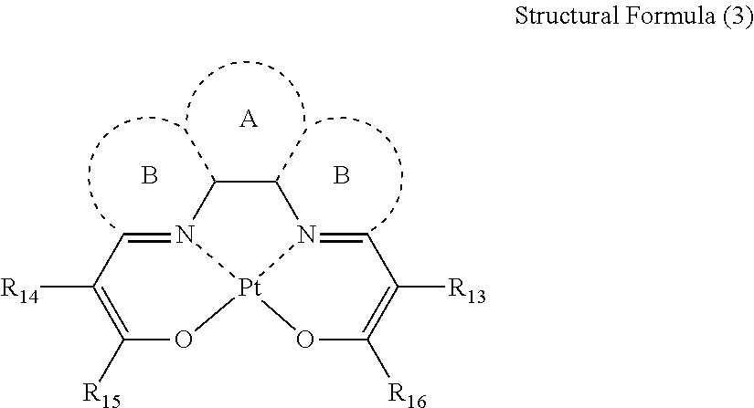


R=(2A∥−A⊥)/A⊥ Equation (1)
S=(R−1)/(R+2) Equation (2)
<Other Compounds>


—Synthesis of Compound 1a—

—Synthesis of Compound 3b—

—Synthesis of Compound 4a—


—Synthesis of Compound 5a—

—Synthesis of Compound 6a—

—Synthesis of Phosphorescent Compound 30—

—Synthesis of Compound 16a—
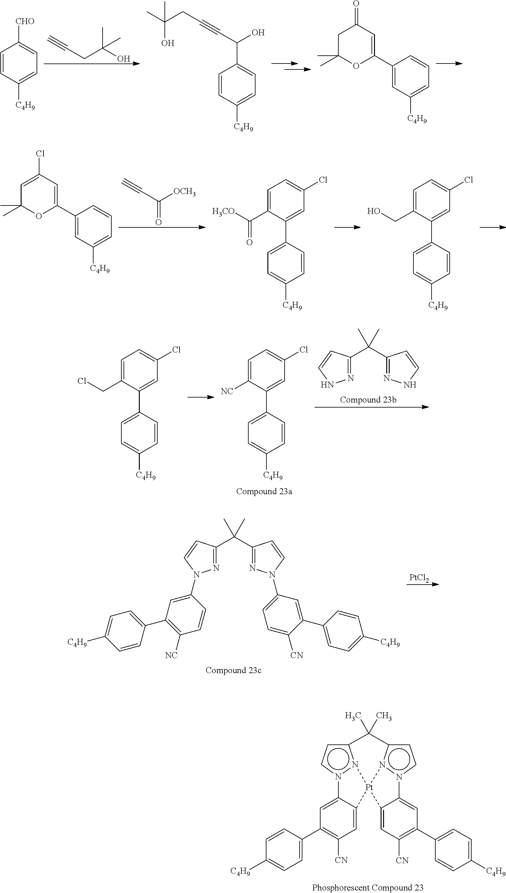
—Synthesis of Compound 23a—

—Synthesis of Host 1a (Host-1a)—


(Evaluation of Materials for Organic Electroluminescence Element 1 to 12 and Comparative Materials for Organic Electroluminescence Element 1 to 9)
—Preparation of Evaluation Cells—
R=(2A∥−A⊥)/A⊥ Equation (1)
S=(R−1)/(R+2) Equation (2)
<Measurement of Polarized Emission Ratio>
| TABLE 1 | ||||||||
| Material | Discotic | |||||||
| for organic | liquid- | |||||||
| electro- | crystalline | Polarized | ||||||
| luminescence | Phosphorescent | Aspect | host | Size | Order | emission | ||
| element | compound | ratio | compound | ratio | parameter | ratio | ||
| Ex. 1 | 1 | 1 | 12.3 | 1 | 1.06 | 0.7 | 3.8 |
| Ex. 2 | 2 | 3 | 12.3 | 1 | 1.06 | 0.62 | 2.8 |
| Ex. 3 | 3 | 4 | 12.3 | 1 | 1.06 | 0.66 | 3.2 |
| Ex. 4 | 4 | 5 | 3.1 | 1 | 1.07 | 0.55 | 2.2 |
| Ex. 5 | 5 | 6 | 3.1 | 1 | 0.96 | 0.58 | 2.4 |
| Ex. 6 | 6 | 30 | 12.3 | 2 | 1.04 | 0.69 | 3.7 |
| Ex. 7 | 7 | 1 | 12.3 | 4 | 1.01 | 0.74 | 4.0 |
| Ex. 8 | 8 | 5 | 3.1 | 4 | 1.02 | 0.72 | 3.8 |
| Ex. 9 | 9 | 1 | 12.3 | 5 | 1.02 | 0.73 | 3.9 |
| Ex. 10 | 10 | 6 | 3.1 | 5 | 0.93 | 0.71 | 3.8 |
| Ex. 11 | 11 | 16 | 5.5 | 6 | 0.96 | 0.62 | 2.8 |
| Ex. 12 | 12 | 23 | 5.4 | 6 | 0.92 | 0.64 | 3.1 |
| Comp. Ex. 1 | Comp. 1 | 1 | 12.3 | 2 | 1.55 | 0.38 | 1.4 |
| Comp. Ex. 2 | Comp. 2 | Comp. 1 | 9.6 | 1 | 0.34 | 0.41 | 1.5 |
| Comp. Ex. 3 | Comp. 3 | Comp. 2 | 4.2 | 1 | 0.43 | 0.42 | 1.5 |
| Comp. Ex. 4 | Comp. 4 | Comp. 1 | 9.6 | 2 | 0.56 | 0.35 | 1.2 |
| Comp. Ex. 5 | Comp. 5 | Comp. 2 | 4.2 | 3 | 0.57 | 0.37 | 1.3 |
| Comp. Ex. 6 | Comp. 6 | Comp. 3 | 2.9 | 1 | 0.86 | 0.4 | 1.4 |
| Comp. Ex. 7 | Comp. 7 | 1 | 12.3 | NLC1 | 1.05 | 0 | 1 |
| Comp. Ex. 8 | Comp. 8 | Comp. 4 | 4.2 | 1 | 0.77 | 0.44 | 1.6 |
| Comp. Ex. 9 | Comp. 9 | Comp. 5 | 4.2 | 2 | 1.23 | 0.4 | 1.4 |
| (In the column of material for organic electroluminescence element, “Comp.” denotes a comparative material for organic electroluminescence element. In the column of phosphorescent compound, “Comp.” denotes a comparative phosphorescent compound. In the column of discotic liquid-crystalline host compound, “NLC” denotes a non-liquid-crystalline host compound.) | |||||||

| TABLE 2 | |||||||
| Discotic | |||||||
| liquid- | |||||||
| Evaluation | Phosphorescent | Aspect | crystalline host | Size | Emission | ||
| substrate | compound | ratio | compound | ratio | distribution | ||
| Example 13 | Evaluation | 1 | 12.3 | 1 | 1.06 | 1.4 |
| Substrate 1 | ||||||
| Example 14 | Evaluation | 3 | 12.3 | 1 | 1.06 | 1.32 |
| |
||||||
| Example 15 | Evaluation | 4 | 12.3 | 1 | 1.06 | 1.36 |
| Substrate 3 | ||||||
| Example 16 | |
5 | 3.1 | 1 | 1.07 | 1.25 |
| Substrate 4 | ||||||
| Example 17 | Evaluation | 6 | 3.1 | 1 | 0.96 | 1.28 |
| |
||||||
| Example 18 | Evaluation | 30 | 12.3 | 2 | 1.04 | 1.39 |
| Substrate 6 | ||||||
| Comp. Ex. 10 | Comparative | 1 | 12.3 | 2 | 1.55 | 1.08 |
| Substrate 1 | ||||||
| Comp. Ex. 11 | Comparative | Comp. 1 | 9.6 | 1 | 0.34 | 1.11 |
| |
||||||
| Comp. Ex. 12 | Comparative | Comp. 2 | 4.2 | 1 | 0.43 | 1.12 |
| Substrate 3 | ||||||
| Comp. Ex. 13 | Comparative | Comp. 1 | 9.6 | 2 | 0.56 | 1.05 |
| Substrate 4 | ||||||
| Comp. Ex. 14 | Comparative | Comp. 2 | 4.2 | 3 | 0.57 | 1.07 |
| |
||||||
| Comp. Ex. 15 | Comparative | Comp. 3 | 2.9 | 1 | 0.86 | 1.1 |
| Substrate 6 | ||||||
| Comp. Ex. 16 | Comparative | 1 | 12.3 | NLC 1 | 1.05 | 1 |
| Substrate 7 | ||||||
| Comp. Ex. 17 | Comparative | Comp. 4 | 4.2 | 1 | 0.77 | 1.14 |
| Substrate 8 | ||||||
| Comp. Ex. 18 | Comparative | Comp. 5 | 4.2 | 2 | 1.23 | 1.1 |
| Substrate 9 | ||||||
| (In Table 2, “comparative substrate” denotes a comparative evaluation substrate. In the column of phosphorescent compound, “Comp.” denotes a comparative phosphorescent compound. In the column of discotic liquid-crystalline host compound, “NLC” denotes a non-liquid-crystalline host compound.) | ||||||


| TABLE 3 | ||||||||
| Organic | Relative | |||||||
| electro- | Light- | external | ||||||
| luminescence | Host | emitting | Size | Order | quantum | Luminance | ||
| element | material | material | ratio | parameter | efficiency | half-life | ||
| Example 19 | A | 1 | 1 | 1.06 | 0.7 | 1.5 | 1.2 |
| Example 20 | B | 1 | 4 | 1.06 | 0.66 | 1.3 | 1.1 |
| Example 21 | C | 4 | 1 | 1.01 | 0.74 | 1.5 | 1.4 |
| Example 22 | |
5 | 1 | 1.02 | 0.73 | 1.5 | 2.1 |
| Example 23 | E | 6 | 16 | 0.96 | 0.62 | 1.3 | 3.5 |
| Example 24 | F | 6 | 23 | 0.92 | 0.64 | 1.3 | 5.7 |
| Comp. Ex. 19 | a | 2 | 1 | 1.55 | 0.38 | 1 | 1 |
| Comp. Ex. 20 | b | 1 | Comp. 2 | 0.43 | 0.42 | 1.1 | 0.9 |


| TABLE 4 | ||||||||
| Organic | Relative | |||||||
| electro- | Light- | external | ||||||
| luminescence | Host | emitting | Size | Order | quantum | Luminance | ||
| element | material | material | ratio | parameter | efficiency | half-life | ||
| Example 25 | G | 1 | 1 | 1.06 | 0.7 | 1.3 | 1.3 |
| Example 26 | H | 1 | 4 | 1.06 | 0.66 | 1.2 | 1.2 |
| Example 27 | I | 4 | 1 | 1.01 | 0.74 | 1.4 | 1.5 |
| Example 28 | |
5 | 1 | 1.02 | 0.73 | 1.4 | 2.3 |
| Example 29 | K | 6 | 16 | 0.96 | 0.62 | 1.4 | 3.2 |
| Example 30 | L | 6 | 23 | 0.92 | 0.64 | 1.7 | 6.3 |
| Comp. Ex. 21 | |
2 | 1 | 1.55 | 0.38 | 1 | 1 |
| Comp. Ex. 22 | d | 1 | Comp. 2 | 0.43 | 0.42 | 1 | 0.9 |
| TABLE 5 | ||||||||
| Organic | Relative | |||||||
| electro- | Light- | external | ||||||
| luminescence | Host | emitting | Size | Order | quantum | Luminance | ||
| element | material | material | ratio | parameter | efficiency | half-life | ||
| Example 31 | M | 1 | 1 | 1.06 | 0.7 | 1.3 | 1.3 |
| Example 32 | N | 1 | 4 | 1.06 | 0.66 | 1.2 | 1.2 |
| Example 33 | O | 4 | 1 | 1.01 | 0.74 | 1.4 | 1.6 |
| Example 34 | |
5 | 1 | 1.02 | 0.73 | 1.3 | 2.3 |
| Example 35 | Q | 6 | 16 | 0.96 | 0.62 | 1.4 | 3.1 |
| Example 36 | R | 6 | 23 | 0.92 | 0.64 | 1.7 | 6.1 |
| Comp. Ex. 23 | |
2 | 1 | 1.55 | 0.38 | 1 | 1 |
| Comp. Ex. 24 | f | 1 | Comp. 2 | 0.43 | 0.42 | 0.8 | 0.7 |
-
- 1 Substrate
- 2 Anode
- 3 Hole injection layer
- 4 Hole transporting layer
- 5 Light-emitting layer
- 6 Electron transporting layer
- 7 Electron injection layer
- 8 Cathode
- 10 Organic electroluminescence element
Claims (11)


Applications Claiming Priority (3)
| Application Number | Priority Date | Filing Date | Title |
|---|---|---|---|
| JP2010084541 | 2010-03-31 | ||
| JP2010-084541 | 2010-03-31 | ||
| PCT/JP2011/058055 WO2011125756A1 (en) | 2010-03-31 | 2011-03-30 | Organic electric-field light-emitting device material, organic electric-field light-emitting device formed of same, and method for manufacturing organic electric-field light-emitting device |
Publications (2)
| Publication Number | Publication Date |
|---|---|
| US20130033174A1 US20130033174A1 (en) | 2013-02-07 |
| US9601705B2 true US9601705B2 (en) | 2017-03-21 |
Family
ID=44762697
Family Applications (1)
| Application Number | Title | Priority Date | Filing Date |
|---|---|---|---|
| US13/638,737 Active 2034-06-05 US9601705B2 (en) | 2010-03-31 | 2011-03-30 | Material for organic electroluminescence element and organic electroluminescence element using the same, and method for manufacturing organic electroluminescence element |
Country Status (7)
| Country | Link |
|---|---|
| US (1) | US9601705B2 (en) |
| EP (1) | EP2555273B1 (en) |
| JP (1) | JP5714379B2 (en) |
| KR (1) | KR101832003B1 (en) |
| CN (1) | CN102934251B (en) |
| TW (1) | TWI490309B (en) |
| WO (1) | WO2011125756A1 (en) |
Cited By (1)
| Publication number | Priority date | Publication date | Assignee | Title |
|---|---|---|---|---|
| US11495711B2 (en) | 2017-11-02 | 2022-11-08 | Guangdong Aglaia Optoelectronic Materials Co., Ltd | Device comprising organometallic complex luminescent material |
Families Citing this family (17)
| Publication number | Priority date | Publication date | Assignee | Title |
|---|---|---|---|---|
| JP5718023B2 (en) * | 2010-11-08 | 2015-05-13 | ユー・ディー・シー アイルランド リミテッド | Organic electroluminescent device and method for producing organic electroluminescent device |
| JP5981736B2 (en) * | 2011-04-12 | 2016-08-31 | ユー・ディー・シー アイルランド リミテッド | ORGANIC ELECTROLUMINESCENT ELEMENT, AND LIGHT EMITTING DEVICE, DISPLAY DEVICE AND LIGHTING DEVICE USING THE ORGANIC ELECTROLUMINESCENT ELEMENT |
| JP5743694B2 (en) * | 2011-04-28 | 2015-07-01 | ユー・ディー・シー アイルランド リミテッド | Donor sheet for organic electroluminescent device, organic electroluminescent device, organic electroluminescent device, and method for producing organic electroluminescent device |
| US10016335B2 (en) * | 2012-03-27 | 2018-07-10 | Electromed, Inc. | Body pulsating apparatus and method |
| US9708530B2 (en) | 2012-11-06 | 2017-07-18 | Empire Technology Development Llc | Organic phosphorescent materials and methods for their preparation and use |
| KR102065904B1 (en) * | 2012-12-07 | 2020-01-15 | 엘지디스플레이 주식회사 | Organic light emitting diode device and liquid crystal type emitting material used for the same |
| JPWO2014157470A1 (en) * | 2013-03-27 | 2017-02-16 | 大電株式会社 | Phosphorescent material and light emitting device |
| US9911931B2 (en) | 2014-06-26 | 2018-03-06 | Universal Display Corporation | Organic electroluminescent materials and devices |
| GB201511300D0 (en) * | 2015-06-26 | 2015-08-12 | Cambridge Display Tech Ltd | Metal complex and organic light-emitting device |
| CN107646147B (en) * | 2015-03-03 | 2021-02-02 | 日产化学工业株式会社 | Compositions comprising a hole carrier compound and a polymeric acid and uses thereof |
| US10252116B2 (en) * | 2015-10-18 | 2019-04-09 | Hyper Ice, Inc. | Vibrating fitness ball |
| JP2018022862A (en) * | 2016-07-20 | 2018-02-08 | 株式会社Joled | Organic electroluminescent element, organic electroluminescent device, and electronic apparatus |
| JP6768534B2 (en) * | 2016-07-20 | 2020-10-14 | 株式会社Joled | Organic electroluminescent devices, organic electroluminescent devices and electronic devices |
| WO2020088582A1 (en) * | 2018-10-31 | 2020-05-07 | Versitech Limited | Platinum (ii) schiff base complexes with increased emission quantum yield for red oled applications |
| US11985888B2 (en) * | 2019-08-12 | 2024-05-14 | The Regents Of The University Of Michigan | Organic electroluminescent device |
| CN110577544A (en) * | 2019-10-25 | 2019-12-17 | 重庆工商大学 | A kind of hexaazatriphenylene derivative and its synthesis method |
| CN115863242B (en) * | 2023-03-02 | 2023-05-09 | 惠科股份有限公司 | Transient substrate and transfer method of light-emitting chip |
Citations (16)
| Publication number | Priority date | Publication date | Assignee | Title |
|---|---|---|---|---|
| JPH10321371A (en) | 1997-05-20 | 1998-12-04 | Asahi Glass Co Ltd | Novel organic electroluminescence device, method for producing the same, and application thereof |
| JP2002043056A (en) | 2000-07-19 | 2002-02-08 | Canon Inc | Light emitting element |
| US20030034722A1 (en) * | 2001-03-14 | 2003-02-20 | Akira Tsuboyama | Light emitting device and display unit which make use of porphyrin derivative compound |
| JP2005082702A (en) | 2003-09-09 | 2005-03-31 | Toyo Ink Mfg Co Ltd | Organic electroluminescent device material and organic electroluminescent device using the same |
| JP2005099248A (en) | 2003-09-24 | 2005-04-14 | Fuji Photo Film Co Ltd | Liquid crystal display device |
| JP2005099481A (en) | 2003-09-25 | 2005-04-14 | Tohoku Pioneer Corp | Dual-mode display |
| JP2005310733A (en) | 2003-06-02 | 2005-11-04 | Fuji Photo Film Co Ltd | Organic electroluminescent element and complex compound |
| US20060182992A1 (en) | 2003-06-02 | 2006-08-17 | Kazumi Nii | Organic electroluminescent devices and metal complex compounds |
| US20060204787A1 (en) | 2005-03-14 | 2006-09-14 | Fuji Photo Film Co., Ltd. | Organic electroluminescent device |
| JP2007019462A (en) | 2005-03-16 | 2007-01-25 | Fujifilm Corp | Organic electroluminescence device |
| JP2007096255A (en) | 2005-03-14 | 2007-04-12 | Fujifilm Corp | Organic electroluminescence device |
| JP2007133279A (en) | 2005-11-14 | 2007-05-31 | Fujifilm Corp | Method for manufacturing substrate for liquid crystal display device, substrate for liquid crystal display device and liquid crystal display device |
| US20090128008A1 (en) | 2005-03-16 | 2009-05-21 | Fujifilm Corporation | Platinum complex compound and organic electroluminescent device |
| US20090261721A1 (en) | 2008-04-22 | 2009-10-22 | Fujifilm Corporation | Organic electroluminescence device, novel platinum complex compound and novel compound capable of being a ligand thereof |
| JP2011046699A (en) | 2009-07-31 | 2011-03-10 | Sumitomo Chemical Co Ltd | Metal complex, composition including the same, and light-emitting element using the same |
| WO2011030883A1 (en) * | 2009-09-14 | 2011-03-17 | Fujifilm Corporation | Color filter and light-emitting display element |
Family Cites Families (16)
| Publication number | Priority date | Publication date | Assignee | Title |
|---|---|---|---|---|
| US2367661A (en) | 1941-12-31 | 1945-01-23 | Du Pont | Process of photopolymerization |
| US2367670A (en) | 1941-12-31 | 1945-01-23 | Du Pont | Cementing process |
| US2448828A (en) | 1946-09-04 | 1948-09-07 | Du Pont | Photopolymerization |
| US2722512A (en) | 1952-10-23 | 1955-11-01 | Du Pont | Photopolymerization process |
| NL108006C (en) | 1957-05-17 | |||
| US3046127A (en) | 1957-10-07 | 1962-07-24 | Du Pont | Photopolymerizable compositions, elements and processes |
| US3549367A (en) | 1968-05-24 | 1970-12-22 | Du Pont | Photopolymerizable compositions containing triarylimidazolyl dimers and p-aminophenyl ketones |
| US4212970A (en) | 1977-11-28 | 1980-07-15 | Fuji Photo Film Co., Ltd. | 2-Halomethyl-5-vinyl-1,3,4-oxadiazole compounds |
| JPS5928328B2 (en) | 1977-11-29 | 1984-07-12 | 富士写真フイルム株式会社 | Photopolymerizable composition |
| DE3337024A1 (en) | 1983-10-12 | 1985-04-25 | Hoechst Ag, 6230 Frankfurt | LIGHT SENSITIVE COMPOUNDS HAVING TRICHLORMETHYL GROUPS, METHOD FOR THE PRODUCTION THEREOF AND LIGHT SENSITIVE MIXTURE CONTAINING THESE COMPOUNDS |
| JP2692035B2 (en) | 1994-05-13 | 1997-12-17 | 富士写真フイルム株式会社 | Thin film manufacturing method |
| JP2587398B2 (en) | 1994-05-31 | 1997-03-05 | 富士写真フイルム株式会社 | Optical compensation sheet, liquid crystal display and color liquid crystal display |
| CN101667626B (en) * | 2003-06-02 | 2012-11-28 | 富士胶片株式会社 | Organic electroluminescent devices and metal complex compounds |
| US7994423B2 (en) | 2004-06-14 | 2011-08-09 | Georgia Tech Research Corporation | Charge-transport materials, methods of fabrication thereof, and methods of use thereof |
| GB0422057D0 (en) | 2004-10-05 | 2004-11-03 | Astrazeneca Ab | Novel compounds |
| US8119255B2 (en) | 2006-12-08 | 2012-02-21 | Universal Display Corporation | Cross-linkable iridium complexes and organic light-emitting devices using the same |
-
2011
- 2011-03-30 US US13/638,737 patent/US9601705B2/en active Active
- 2011-03-30 KR KR1020127027235A patent/KR101832003B1/en active Active
- 2011-03-30 CN CN201180027097.XA patent/CN102934251B/en active Active
- 2011-03-30 JP JP2011075917A patent/JP5714379B2/en active Active
- 2011-03-30 EP EP11765656.1A patent/EP2555273B1/en active Active
- 2011-03-30 WO PCT/JP2011/058055 patent/WO2011125756A1/en not_active Ceased
- 2011-03-31 TW TW100111274A patent/TWI490309B/en active
Patent Citations (20)
| Publication number | Priority date | Publication date | Assignee | Title |
|---|---|---|---|---|
| JPH10321371A (en) | 1997-05-20 | 1998-12-04 | Asahi Glass Co Ltd | Novel organic electroluminescence device, method for producing the same, and application thereof |
| JP2002043056A (en) | 2000-07-19 | 2002-02-08 | Canon Inc | Light emitting element |
| US20020038860A1 (en) | 2000-07-19 | 2002-04-04 | Akira Tsuboyama | Luminescence device |
| US20030034722A1 (en) * | 2001-03-14 | 2003-02-20 | Akira Tsuboyama | Light emitting device and display unit which make use of porphyrin derivative compound |
| US20090174324A1 (en) | 2003-06-02 | 2009-07-09 | Fujifilm Corporation | Organic electroluminescent devices and metal complex compounds |
| JP2005310733A (en) | 2003-06-02 | 2005-11-04 | Fuji Photo Film Co Ltd | Organic electroluminescent element and complex compound |
| US20060182992A1 (en) | 2003-06-02 | 2006-08-17 | Kazumi Nii | Organic electroluminescent devices and metal complex compounds |
| JP2005082702A (en) | 2003-09-09 | 2005-03-31 | Toyo Ink Mfg Co Ltd | Organic electroluminescent device material and organic electroluminescent device using the same |
| JP2005099248A (en) | 2003-09-24 | 2005-04-14 | Fuji Photo Film Co Ltd | Liquid crystal display device |
| JP2005099481A (en) | 2003-09-25 | 2005-04-14 | Tohoku Pioneer Corp | Dual-mode display |
| US20060204787A1 (en) | 2005-03-14 | 2006-09-14 | Fuji Photo Film Co., Ltd. | Organic electroluminescent device |
| JP2007096255A (en) | 2005-03-14 | 2007-04-12 | Fujifilm Corp | Organic electroluminescence device |
| JP2007019462A (en) | 2005-03-16 | 2007-01-25 | Fujifilm Corp | Organic electroluminescence device |
| US20090128008A1 (en) | 2005-03-16 | 2009-05-21 | Fujifilm Corporation | Platinum complex compound and organic electroluminescent device |
| JP2007133279A (en) | 2005-11-14 | 2007-05-31 | Fujifilm Corp | Method for manufacturing substrate for liquid crystal display device, substrate for liquid crystal display device and liquid crystal display device |
| US20090261721A1 (en) | 2008-04-22 | 2009-10-22 | Fujifilm Corporation | Organic electroluminescence device, novel platinum complex compound and novel compound capable of being a ligand thereof |
| JP2009283891A (en) | 2008-04-22 | 2009-12-03 | Fujifilm Corp | Organic electroluminescence device, novel platinum complex compound and novel compound capable of being ligand thereof |
| JP2011046699A (en) | 2009-07-31 | 2011-03-10 | Sumitomo Chemical Co Ltd | Metal complex, composition including the same, and light-emitting element using the same |
| EP2460788A1 (en) | 2009-07-31 | 2012-06-06 | Sumitomo Chemical Company, Limited | Metal complex, composition comprising same and light-emitting element using same |
| WO2011030883A1 (en) * | 2009-09-14 | 2011-03-17 | Fujifilm Corporation | Color filter and light-emitting display element |
Non-Patent Citations (1)
| Title |
|---|
| Lussem, G., et al., "Liquid Crystalline Materials for Light-emitting Diodes," Polymers for Advanced Technologies, Jul. 1998, pp. 443-460, vol. 9, No. 7. |
Cited By (1)
| Publication number | Priority date | Publication date | Assignee | Title |
|---|---|---|---|---|
| US11495711B2 (en) | 2017-11-02 | 2022-11-08 | Guangdong Aglaia Optoelectronic Materials Co., Ltd | Device comprising organometallic complex luminescent material |
Also Published As
| Publication number | Publication date |
|---|---|
| KR20130020778A (en) | 2013-02-28 |
| CN102934251B (en) | 2015-08-12 |
| EP2555273A4 (en) | 2016-03-30 |
| EP2555273B1 (en) | 2017-09-27 |
| TW201139614A (en) | 2011-11-16 |
| JP5714379B2 (en) | 2015-05-07 |
| WO2011125756A1 (en) | 2011-10-13 |
| JP2011228686A (en) | 2011-11-10 |
| KR101832003B1 (en) | 2018-02-26 |
| CN102934251A (en) | 2013-02-13 |
| EP2555273A1 (en) | 2013-02-06 |
| TWI490309B (en) | 2015-07-01 |
| US20130033174A1 (en) | 2013-02-07 |
Similar Documents
| Publication | Publication Date | Title |
|---|---|---|
| US9601705B2 (en) | Material for organic electroluminescence element and organic electroluminescence element using the same, and method for manufacturing organic electroluminescence element | |
| CN109564982B (en) | Organic Light Emitting Devices | |
| US9882149B2 (en) | Compound for organic optoelectric device, organic optoelectronic device comprsing same, and display apparatus comprising organic optoelectric device | |
| KR101838675B1 (en) | Organic electroluminescent element | |
| KR102005723B1 (en) | Organic electroluminescent element | |
| KR101759966B1 (en) | Organic electroluminescent device | |
| US7955716B2 (en) | Metal coordination compound, polymer composition, and organic electroluminescent device employing same | |
| US20150021585A1 (en) | Composition for organic light-emitting diode, organic light-emitting layer including same, and organic light-emitting diode | |
| US9419231B2 (en) | Organic electroluminescence device | |
| US10505124B2 (en) | Carbazole-based compound and organic light-emitting device including the same | |
| US20170069853A1 (en) | Condensed cyclic comopund and organic light-emitting device including the same | |
| US20200388766A1 (en) | Compound for organic optoelectronic diode, composition for organic optoelectronic diode, organic optoelectronic diode and display device | |
| US20130105786A1 (en) | Novel spiro(anthracene-9,9'-fluoren)-10-one compound and organic light-emitting device including the same | |
| US12161045B2 (en) | Pyrromethene boron complex, light emitting element using same, display device, lighting device, color conversion composition, color conversion film, color conversion substrate, light source unit and display | |
| US12286446B2 (en) | Organometallic compound, organic light- emitting device including the same, and diagnostic composition including the organometallic compound | |
| CN112771031A (en) | Compound, light-emitting material, delayed phosphor, organic light-emitting element, oxygen sensor, method for designing molecule, and program | |
| KR20210002670A (en) | Organic electroluminescent materials and devices | |
| JP5577122B2 (en) | Organic electroluminescence device | |
| US10096784B2 (en) | Compound for organic optoelectric device, composition for organic optoelectric device and organic optoelectric device and display device | |
| US11690288B2 (en) | Composition for organic optoelectronic diode, organic optoelectronic diode, and display device | |
| US10096777B2 (en) | Composition for organic optoelectric device and organic optoelectric device and display device | |
| JP5718023B2 (en) | Organic electroluminescent device and method for producing organic electroluminescent device | |
| US12122732B2 (en) | Functionalized polycyclic aromatic hydrocarbon compound and light-emitting device including the same | |
| US20190312209A1 (en) | Condensed cyclic compound and organic light-emitting device including the same | |
| JP5886928B2 (en) | Material for organic electroluminescent element, film containing the same, and organic electroluminescent element |
Legal Events
| Date | Code | Title | Description |
|---|---|---|---|
| AS | Assignment |
Owner name: UNIVERAL DISPLAY CORPORATION IRELAND LIMITED, IREL Free format text: ASSIGNMENT OF ASSIGNORS INTEREST;ASSIGNOR:TAKAKU, KOJI;REEL/FRAME:029056/0578 Effective date: 20120907 |
|
| AS | Assignment |
Owner name: UDC IRELAND LIMITED, IRELAND Free format text: ASSIGNMENT OF ASSIGNORS INTEREST;ASSIGNOR:FUJIFILM CORPORATION;REEL/FRAME:029731/0363 Effective date: 20120726 |
|
| AS | Assignment |
Owner name: UDC IRELAND LIMITED, IRELAND Free format text: ASSIGNMENT OF ASSIGNORS INTEREST;ASSIGNOR:FUJIFILM CORPORATION;REEL/FRAME:029760/0235 Effective date: 20120726 |
|
| FEPP | Fee payment procedure |
Free format text: PAYOR NUMBER ASSIGNED (ORIGINAL EVENT CODE: ASPN); ENTITY STATUS OF PATENT OWNER: LARGE ENTITY |
|
| STCF | Information on status: patent grant |
Free format text: PATENTED CASE |
|
| MAFP | Maintenance fee payment |
Free format text: PAYMENT OF MAINTENANCE FEE, 4TH YEAR, LARGE ENTITY (ORIGINAL EVENT CODE: M1551); ENTITY STATUS OF PATENT OWNER: LARGE ENTITY Year of fee payment: 4 |
|
| MAFP | Maintenance fee payment |
Free format text: PAYMENT OF MAINTENANCE FEE, 8TH YEAR, LARGE ENTITY (ORIGINAL EVENT CODE: M1552); ENTITY STATUS OF PATENT OWNER: LARGE ENTITY Year of fee payment: 8 |