US9597854B2 - Resin laminated plate - Google Patents

Resin laminated plate Download PDF

Info

Publication number
US9597854B2
US9597854B2 US14/915,345 US201414915345A US9597854B2 US 9597854 B2 US9597854 B2 US 9597854B2 US 201414915345 A US201414915345 A US 201414915345A US 9597854 B2 US9597854 B2 US 9597854B2
Authority
US
United States
Prior art keywords
back side
region
concave
front side
concave ribs
Prior art date
Legal status (The legal status is an assumption and is not a legal conclusion. Google has not performed a legal analysis and makes no representation as to the accuracy of the status listed.)
Active
Application number
US14/915,345
Other versions
US20160207276A1 (en
Inventor
Kenji Ishii
Tadatoshi Tanji
Current Assignee (The listed assignees may be inaccurate. Google has not performed a legal analysis and makes no representation or warranty as to the accuracy of the list.)
Kyoraku Co Ltd
Original Assignee
Kyoraku Co Ltd
Priority date (The priority date is an assumption and is not a legal conclusion. Google has not performed a legal analysis and makes no representation as to the accuracy of the date listed.)
Filing date
Publication date
Application filed by Kyoraku Co Ltd filed Critical Kyoraku Co Ltd
Assigned to KYORAKU CO., LTD. reassignment KYORAKU CO., LTD. ASSIGNMENT OF ASSIGNORS INTEREST (SEE DOCUMENT FOR DETAILS). Assignors: TANJI, TADATOSHI, ISHII, KENJI
Publication of US20160207276A1 publication Critical patent/US20160207276A1/en
Application granted granted Critical
Publication of US9597854B2 publication Critical patent/US9597854B2/en
Active legal-status Critical Current
Anticipated expiration legal-status Critical

Links

Images

Classifications

    • BPERFORMING OPERATIONS; TRANSPORTING
    • B32LAYERED PRODUCTS
    • B32BLAYERED PRODUCTS, i.e. PRODUCTS BUILT-UP OF STRATA OF FLAT OR NON-FLAT, e.g. CELLULAR OR HONEYCOMB, FORM
    • B32B3/00Layered products comprising a layer with external or internal discontinuities or unevennesses, or a layer of non-planar shape; Layered products comprising a layer having particular features of form
    • B32B3/26Layered products comprising a layer with external or internal discontinuities or unevennesses, or a layer of non-planar shape; Layered products comprising a layer having particular features of form characterised by a particular shape of the outline of the cross-section of a continuous layer; characterised by a layer with cavities or internal voids ; characterised by an apertured layer
    • B32B3/30Layered products comprising a layer with external or internal discontinuities or unevennesses, or a layer of non-planar shape; Layered products comprising a layer having particular features of form characterised by a particular shape of the outline of the cross-section of a continuous layer; characterised by a layer with cavities or internal voids ; characterised by an apertured layer characterised by a layer formed with recesses or projections, e.g. hollows, grooves, protuberances, ribs
    • BPERFORMING OPERATIONS; TRANSPORTING
    • B32LAYERED PRODUCTS
    • B32BLAYERED PRODUCTS, i.e. PRODUCTS BUILT-UP OF STRATA OF FLAT OR NON-FLAT, e.g. CELLULAR OR HONEYCOMB, FORM
    • B32B27/00Layered products comprising a layer of synthetic resin
    • B32B27/06Layered products comprising a layer of synthetic resin as the main or only constituent of a layer, which is next to another layer of the same or of a different material
    • B32B27/08Layered products comprising a layer of synthetic resin as the main or only constituent of a layer, which is next to another layer of the same or of a different material of synthetic resin
    • BPERFORMING OPERATIONS; TRANSPORTING
    • B32LAYERED PRODUCTS
    • B32BLAYERED PRODUCTS, i.e. PRODUCTS BUILT-UP OF STRATA OF FLAT OR NON-FLAT, e.g. CELLULAR OR HONEYCOMB, FORM
    • B32B2307/00Properties of the layers or laminate
    • B32B2307/70Other properties
    • B32B2307/718Weight, e.g. weight per square meter
    • BPERFORMING OPERATIONS; TRANSPORTING
    • B32LAYERED PRODUCTS
    • B32BLAYERED PRODUCTS, i.e. PRODUCTS BUILT-UP OF STRATA OF FLAT OR NON-FLAT, e.g. CELLULAR OR HONEYCOMB, FORM
    • B32B2419/00Buildings or parts thereof
    • BPERFORMING OPERATIONS; TRANSPORTING
    • B32LAYERED PRODUCTS
    • B32BLAYERED PRODUCTS, i.e. PRODUCTS BUILT-UP OF STRATA OF FLAT OR NON-FLAT, e.g. CELLULAR OR HONEYCOMB, FORM
    • B32B2553/00Packaging equipment or accessories not otherwise provided for
    • BPERFORMING OPERATIONS; TRANSPORTING
    • B32LAYERED PRODUCTS
    • B32BLAYERED PRODUCTS, i.e. PRODUCTS BUILT-UP OF STRATA OF FLAT OR NON-FLAT, e.g. CELLULAR OR HONEYCOMB, FORM
    • B32B2605/00Vehicles

Definitions

  • the present invention relates to a resin laminate.
  • resin laminates are conventionally employed for interior materials of automobiles, building materials, and materials for logistics and packaging.
  • Such resin laminate has a front surface material made of a resin and a back surface material made of a resin.
  • the back surface material is provided with concave ribs having tip ends to be abutted on the internal surface of the front surface material.
  • various methods have been employed conventionally.
  • PTL 1 discloses a method as follows.
  • PLT 1 Japanese Unexamined Patent Application Publication No. 2013-10273
  • a resin laminate having a flat surface of a front side sheet is assumed, where a back side sheet is provided with a step to form a thick plate area and a thin plate area in the resin laminate.
  • the concave ribs having the back side sheet recessed towards the front side sheet have the depth in the thick plate area deeper than the depth in the thin plate area.
  • a front side sheet 3 of a resin laminate 1 is sometimes provided with a convex region 3 a and flat regions 3 b .
  • concave ribs 7 a with a back side sheet 5 recessed towards the front side sheet 3 in a manner same as that in PTL 1 have the depth in the convex region 3 a deeper than the depth in the flat regions 3 b .
  • the concave ribs 7 a formed in the convex region 3 a therefore, have a thickness thinner than the thickness of concave ribs 7 b formed in the flat regions 3 b .
  • the entire thickness has to be thicker to prevent pinholes in the thinnest area, leading to increase in weight of the resin laminate.
  • the present invention has been made in view of such circumstances and provides a resin laminate that is capable of equalizing the depth of concave ribs provided in a back side sheet even when there are flat regions and a convex region in a front side sheet of the resin laminate.
  • a resin laminate includes: a front side sheet; and a back side sheet, both stacked across a hollow, the back side sheet being recessed into the hollow to provide a large number of concave ribs and a bottom of the large number of concave ribs welded to the front side sheet to couple the front side sheet to the back side sheet by the large number of concave ribs, wherein the front side sheet is provided with a front side flat region configured with a flat surface and a front side convex region projecting to an opposite side of the hollow, the back side sheet is provided with a back side flat region configured with a flat surface and a back side concave region recessed into the hollow, the front side convex region and the back side concave region are provided in a position facing each other, and at least one of the concave ribs is provided for each of the front side convex region and the front side flat region.
  • the present inventors have made various investigations to achieve the above object. As a result, they have come up with an idea of providing a concave region in a back side sheet so as to face a convex region of a front side sheet. Then, by providing a concave region in this position, it is possible to reduce a difference between the depth of the concave ribs in the convex region of the front side sheet and the depth of the concave ribs in the flat regions of the front side sheet, and thus they have come to complete the present invention. In addition, by equalizing the depth of the concave ribs, the thickness of the concave ribs is equalized. Then, by equalizing the thickness of the concave ribs, pinholes do not easily occur even when the back side sheet is thinned, thereby enabling reduction in thickness, that is, reduction in weight of the back side sheet.
  • the front side convex region has a length in a height direction substantially equal to a length in a depth direction of the back side concave region.
  • the front side convex region has a shape fitting into the back side concave region.
  • the large number of concave ribs are arranged to substantially form an equilateral triangle with a line connecting centers of adjacent three of the concave ribs.
  • the adjacent three of the concave ribs at a border between the back side concave region and the back side flat region include the concave ribs provided in the back side concave region and the concave ribs provided in the back side flat region.
  • a border line between the back side concave region and the back side flat region is provided between the concave ribs provided in the back side concave region and the concave ribs provided in the back side flat region.
  • FIG. 1 illustrate a configuration of a resin laminate 1 in a first embodiment of the present invention, where (a) is a plan view taken from a front side sheet 3 side, (c) is a bottom view taken from a back side sheet 5 side, and (b) is an A-A cross-sectional view of (c).
  • FIGS. 2( a ) and ( b ) are cross-sectional views corresponding to FIG. 1( b ) , where (a) illustrates a state of vertically arranging two resin laminates 1 in FIG. 1 in alignment and (b) illustrates a state of stacking two resin laminates 1 .
  • FIG. 3 illustrates a step of closely adhering melted resin sheets 13 and 14 to molds 11 and 12 in a procedure of manufacturing the resin laminate 1 in FIG. 1 .
  • FIG. 4 is a diagram illustrating the procedure of manufacturing the resin laminate 1 following FIG. 3 and illustrates a state after closing the molds.
  • FIG. 5( a ) is a cross-sectional view of a resin laminate 1 in a second embodiment of the present invention corresponding to FIGS. 1( b ), and 5( b ) illustrates a state of vertically stacking two resin laminates 1 in 5 ( a ).
  • FIG. 6 is a reference drawing to illustrate the problems for the present invention and is a cross-sectional view corresponding to FIG. 1( b ) .
  • a resin laminate 1 in the first embodiment of the present invention is provided with a front side sheet 3 and a back side sheet 5 that are stacked across a hollow 2 .
  • a large number of concave ribs 7 a and 7 b are formed by causing the back side sheet 5 recessed into the hollow 2 .
  • the bottom of the respective concave ribs 7 a and 7 b is welded to the front side sheet 3 , thereby coupling the front side sheet 3 to the back side sheet 5 by the large number of concave ribs 7 a and 7 b .
  • the front side sheet 3 is provided with front side flat regions 3 b configured with a flat surface and a front side convex region 3 a projecting to the opposite side of the hollow 2 .
  • the back side sheet 5 is provided with back side flat regions 5 b configured with a flat surface and a back side concave region 5 a recessed into the hollow 2 .
  • the front side convex region 3 a and the back side concave region 5 a are provided in a position facing each other.
  • the large number of concave ribs 7 a are formed in the front side convex region 3 a
  • the large number of concave ribs 7 b are formed in the front side flat regions 3 b.
  • the back side concave region 5 a is not formed in the back side sheet 5 as illustrated in FIG. 6 , there used to be a problem that the concave ribs 7 a provided in the front side convex region 3 a have a depth deeper than the depth of the concave ribs 7 b provided in the front side flat regions 3 b and the thickness becomes thinner accordingly.
  • the back side concave region 5 a is provided to face the front side convex region 3 a , and thus deepening of the concave ribs in the front side convex region 3 a may be suppressed.
  • the front side convex region 3 a has a length in the height direction substantially equal to the length in the depth direction of the back side concave region 5 a , and thus the concave ribs 7 a have a depth substantially identical to the depth of the concave ribs 7 b .
  • the length in the height direction of the front side convex region 3 a does not have to match the length in the depth direction of the back side concave region 5 a , and there may be a difference in the lengths.
  • the depth of the concave ribs 7 a and the depth of the concave ribs 7 b do not become completely same but the difference in the depth is less than that in the mode illustrated in FIG. 6 .
  • the effect of the present invention to equalize the depth of the concave ribs is thus obtained.
  • the front side convex region 3 a has a shape fitting into the back side concave region 5 a .
  • FIGS. 2( a ) and 2( b ) when a plurality of resin laminates 1 are stacked, such shape allows volume reduction by having the front side convex region 3 a entering the back side concave region 5 a .
  • the plurality of stacked resin laminates 1 are suppressed from horizontal movement to each other, which may cause flaws on the surface of the resin laminates 1 .
  • the concave ribs 7 a and 7 b are arranged to substantially form an equilateral triangle with a line connecting centers of adjacent three of the concave ribs.
  • the back side concave region 5 a is provided with the large number of concave ribs 7 a
  • the concave ribs 7 a are arranged to form an equilateral triangle Ta with a line connecting the centers of adjacent three of the concave ribs 7 a .
  • the back side flat regions 5 b are provided with the large number of concave ribs 7 b , and the concave ribs 7 b are arranged to form an equilateral triangle Tb with a line connecting the centers of adjacent three of the concave ribs 7 b.
  • the concave ribs 7 a and 7 b are arranged to form an equilateral triangle Tab with a line connecting the centers of adjacent three of the concave ribs including 7 a and 7 b .
  • the large number of concave ribs are uniformly arranged at an identical pitch over the back side concave region 5 a and the back side flat regions 5 b .
  • the border BB between the back side concave region 5 a and the back side flat regions 5 b is provided in zigzag to weave between the concave ribs 7 a and 7 b .
  • the border BB may avoid overlap with the concave ribs, and thus mold design is facilitated. Meanwhile, there is no concave rib in the front surface side.
  • a border FB between the front side convex region 3 a and the front side flat regions 3 b may thus be freely designed. It may be, as illustrated in FIG. 1( a ) for example, linear.
  • One of the points of the present invention is to avoid complex mold design by differentiating the shapes of the borders BB and FB in such a manner.
  • a method of manufacturing the resin laminate 1 in the present embodiment is described.
  • a pair of molds 11 and 12 in accordance with the shape of the resin laminate 1 are prepared.
  • the melted resin sheets 13 and 14 are closely adhered to the molds 11 and 12 .
  • the molds 11 and 12 are closed to sandwich the melted resin sheets 13 and 14 .
  • the molds 11 and 12 are provided with pinch-offs 11 b and 12 b to surround a cavity 15 formed inside the molds 11 and 12 .
  • the melted resin sheets 13 and 14 are pinched and crushed by the pinch-offs 11 b and 12 b .
  • the areas outside the cavity 15 become burrs 16 and the areas pinched by the pinch-offs 11 b and 12 b become cut-off lines for the burrs 16 .
  • air may be optionally blown in the cavity 15 .
  • the molds 11 and 12 are opened to remove the molded product and the burrs 16 are cut on the cut-off lines formed in the molded product by the pinch-offs 11 b and 12 b and eliminated.
  • the resin laminate 1 illustrated in FIG. 1 is formed.
  • the resin laminate 1 in the present embodiment is similar to that in the first embodiment, and the configuration of the front side convex region 3 a and the back side concave region 5 a is mainly different. The following description is given mainly to such points.
  • the front side convex region 3 a has a size substantially identical to that of the back side concave region 5 a .
  • the plurality of stacked resin laminates 1 is almost unmovable horizontally.
  • the back side concave region 5 a is larger than the front side convex region 3 a .
  • the plurality of stacked resin laminates 1 is thus relatively movable horizontally within the range illustrated with arrows D in FIG.
  • the resin laminate 1 in the present embodiment is allowed to relatively move slightly in the horizontal direction when stacked, and thus the effect of suppressing flaws in the resin laminate 1 may be worse than that in the first embodiment. Instead, the front side convex region 3 a is easily inserted into the back side concave region 5 a and there is an advantage of easy stacking of a plurality of resin laminates 1 .
  • the front side convex region 3 a and the back side concave region 5 a occupy a substantially same region, and thus there are the concave ribs 7 a provided in the front side convex region 3 a and the concave ribs 7 b provided in the front side flat regions 3 b .
  • the back side concave region 5 a is wider than the front side convex region 3 a , and thus in addition to the concave ribs 7 a and 7 b , concave ribs 7 c shallower than the concave ribs 7 a are provided in the regions where the back side concave region 5 a overlaps with the front side flat regions 3 b.
  • the borders FB and BB have a substantially identical angle of inclination.
  • the border FB has an angle of inclination less than that of the border BB.
  • the borders FB and BB may thus have different angles of inclination.
  • the borders FB and BB are inclined surfaces in the first and second embodiments, these borders may be surfaces substantially vertical to the front surface or the back surface of the resin laminate 1 .

Landscapes

  • Laminated Bodies (AREA)
  • Moulds For Moulding Plastics Or The Like (AREA)
  • Lining Or Joining Of Plastics Or The Like (AREA)
  • Blow-Moulding Or Thermoforming Of Plastics Or The Like (AREA)

Abstract

Provided is a resin laminates in which the depth of concave ribs provided to a back side sheet can be made uniform, even when a convex region and flat regions are present on an front side sheet of the resin laminate. The resin laminate is provided with the front side sheet and the back side sheet, which overlap with a hollow interposed therebetween. The back side sheet is recessed into the hollow, and a large number of concave ribs are provided. The bottoms of the concave ribs are fused to the front side sheet. The front side sheet is provided with front side flat region configured from a flat surface and a front side convex region protruding away from the hollow. The back side sheet is provided with back side flat region configured from a flat surface and a back side concave region recessed into the hollow.

Description

TECHNICAL FIELD
The present invention relates to a resin laminate.
BACKGROUND ART
So-called resin laminates are conventionally employed for interior materials of automobiles, building materials, and materials for logistics and packaging. Such resin laminate has a front surface material made of a resin and a back surface material made of a resin. The back surface material is provided with concave ribs having tip ends to be abutted on the internal surface of the front surface material. For a method of manufacturing such resin laminate, various methods have been employed conventionally.
For example, PTL 1 discloses a method as follows.
That is, using a split mold in which a cavity in one piece of the split mold is provided with a plurality of projections projecting towards the other piece of the split mold, two sheet materials made of a thermoplastic resin in a molten state is positioned between the pair of split mold pieces. Then, after an enclosed space is formed between one of the sheet materials and the cavity in the one piece of the split mold, the air in the enclosed space is sucked from the side of the one piece of the split mold. By the suction action, a plurality of concave ribs are formed in the sheet material at the plurality of projections. By closing the pair of split mold pieces, the bottom of the concave ribs is welded to the other sheet material to obtain a resin laminate having a hollow structure reinforced by the plurality of ribs.
Use of such manufacturing technique enables maximum thinning of the respective thicknesses of the two sheet materials, thereby enabling reduction in weight and thickness while securing the manufacturing efficiency and the product quality.
CITATION LIST Patent Literature
PLT 1: Japanese Unexamined Patent Application Publication No. 2013-10273
SUMMARY OF INVENTION Technical Problem
In PTL 1, a resin laminate having a flat surface of a front side sheet is assumed, where a back side sheet is provided with a step to form a thick plate area and a thin plate area in the resin laminate. The concave ribs having the back side sheet recessed towards the front side sheet have the depth in the thick plate area deeper than the depth in the thin plate area.
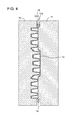
As illustrated in FIG. 6, a front side sheet 3 of a resin laminate 1 is sometimes provided with a convex region 3 a and flat regions 3 b. In such a case, concave ribs 7 a with a back side sheet 5 recessed towards the front side sheet 3 in a manner same as that in PTL 1 have the depth in the convex region 3 a deeper than the depth in the flat regions 3 b. The concave ribs 7 a formed in the convex region 3 a, therefore, have a thickness thinner than the thickness of concave ribs 7 b formed in the flat regions 3 b. When the thicknesses of the concave ribs 7 a and 7 b are different in such a manner, the entire thickness has to be thicker to prevent pinholes in the thinnest area, leading to increase in weight of the resin laminate.
The present invention has been made in view of such circumstances and provides a resin laminate that is capable of equalizing the depth of concave ribs provided in a back side sheet even when there are flat regions and a convex region in a front side sheet of the resin laminate.
Solution to Problem
According to the present invention, a resin laminate is provided that includes: a front side sheet; and a back side sheet, both stacked across a hollow, the back side sheet being recessed into the hollow to provide a large number of concave ribs and a bottom of the large number of concave ribs welded to the front side sheet to couple the front side sheet to the back side sheet by the large number of concave ribs, wherein the front side sheet is provided with a front side flat region configured with a flat surface and a front side convex region projecting to an opposite side of the hollow, the back side sheet is provided with a back side flat region configured with a flat surface and a back side concave region recessed into the hollow, the front side convex region and the back side concave region are provided in a position facing each other, and at least one of the concave ribs is provided for each of the front side convex region and the front side flat region.
The present inventors have made various investigations to achieve the above object. As a result, they have come up with an idea of providing a concave region in a back side sheet so as to face a convex region of a front side sheet. Then, by providing a concave region in this position, it is possible to reduce a difference between the depth of the concave ribs in the convex region of the front side sheet and the depth of the concave ribs in the flat regions of the front side sheet, and thus they have come to complete the present invention. In addition, by equalizing the depth of the concave ribs, the thickness of the concave ribs is equalized. Then, by equalizing the thickness of the concave ribs, pinholes do not easily occur even when the back side sheet is thinned, thereby enabling reduction in thickness, that is, reduction in weight of the back side sheet.
Various embodiments of the present invention are exemplified below. The embodiments shown below may be combined with each other.
It is preferred that the front side convex region has a length in a height direction substantially equal to a length in a depth direction of the back side concave region.
It is preferred that the front side convex region has a shape fitting into the back side concave region.
It is preferred that the large number of concave ribs are arranged to substantially form an equilateral triangle with a line connecting centers of adjacent three of the concave ribs.
It is preferred that the adjacent three of the concave ribs at a border between the back side concave region and the back side flat region include the concave ribs provided in the back side concave region and the concave ribs provided in the back side flat region.
It is preferred that a border line between the back side concave region and the back side flat region is provided between the concave ribs provided in the back side concave region and the concave ribs provided in the back side flat region.
BRIEF DESCRIPTION OF DRAWINGS
FIG. 1 illustrate a configuration of a resin laminate 1 in a first embodiment of the present invention, where (a) is a plan view taken from a front side sheet 3 side, (c) is a bottom view taken from a back side sheet 5 side, and (b) is an A-A cross-sectional view of (c).
FIGS. 2(a) and (b) are cross-sectional views corresponding to FIG. 1(b), where (a) illustrates a state of vertically arranging two resin laminates 1 in FIG. 1 in alignment and (b) illustrates a state of stacking two resin laminates 1.
FIG. 3 illustrates a step of closely adhering melted resin sheets 13 and 14 to molds 11 and 12 in a procedure of manufacturing the resin laminate 1 in FIG. 1.
FIG. 4 is a diagram illustrating the procedure of manufacturing the resin laminate 1 following FIG. 3 and illustrates a state after closing the molds.
FIG. 5(a) is a cross-sectional view of a resin laminate 1 in a second embodiment of the present invention corresponding to FIGS. 1(b), and 5(b) illustrates a state of vertically stacking two resin laminates 1 in 5(a).
FIG. 6 is a reference drawing to illustrate the problems for the present invention and is a cross-sectional view corresponding to FIG. 1(b).
DESCRIPTION OF EMBODIMENTS
With reference to the drawings, embodiments of the present invention are described below.
1. First Embodiment
As illustrated in FIG. 1, a resin laminate 1 in the first embodiment of the present invention is provided with a front side sheet 3 and a back side sheet 5 that are stacked across a hollow 2. In the back side sheet 5, a large number of concave ribs 7 a and 7 b are formed by causing the back side sheet 5 recessed into the hollow 2. The bottom of the respective concave ribs 7 a and 7 b is welded to the front side sheet 3, thereby coupling the front side sheet 3 to the back side sheet 5 by the large number of concave ribs 7 a and 7 b. The front side sheet 3 is provided with front side flat regions 3 b configured with a flat surface and a front side convex region 3 a projecting to the opposite side of the hollow 2. The back side sheet 5 is provided with back side flat regions 5 b configured with a flat surface and a back side concave region 5 a recessed into the hollow 2. The front side convex region 3 a and the back side concave region 5 a are provided in a position facing each other. The large number of concave ribs 7 a are formed in the front side convex region 3 a, and the large number of concave ribs 7 b are formed in the front side flat regions 3 b.
As described above, in a mode where the back side concave region 5 a is not formed in the back side sheet 5 as illustrated in FIG. 6, there used to be a problem that the concave ribs 7 a provided in the front side convex region 3 a have a depth deeper than the depth of the concave ribs 7 b provided in the front side flat regions 3 b and the thickness becomes thinner accordingly. In the present embodiment, the back side concave region 5 a is provided to face the front side convex region 3 a, and thus deepening of the concave ribs in the front side convex region 3 a may be suppressed. In the embodiment illustrated in FIG. 1, the front side convex region 3 a has a length in the height direction substantially equal to the length in the depth direction of the back side concave region 5 a, and thus the concave ribs 7 a have a depth substantially identical to the depth of the concave ribs 7 b. The length in the height direction of the front side convex region 3 a, however, does not have to match the length in the depth direction of the back side concave region 5 a, and there may be a difference in the lengths. In this case, the depth of the concave ribs 7 a and the depth of the concave ribs 7 b do not become completely same but the difference in the depth is less than that in the mode illustrated in FIG. 6. The effect of the present invention to equalize the depth of the concave ribs is thus obtained.
In the embodiment illustrated in FIG. 1, the front side convex region 3 a has a shape fitting into the back side concave region 5 a. As illustrated in FIGS. 2(a) and 2(b), when a plurality of resin laminates 1 are stacked, such shape allows volume reduction by having the front side convex region 3 a entering the back side concave region 5 a. In the state of the front side convex region 3 a entering the back side concave region 5 a, the plurality of stacked resin laminates 1 are suppressed from horizontal movement to each other, which may cause flaws on the surface of the resin laminates 1.
Then, with reference to FIG. 1(c), distribution of the concave ribs 7 a and 7 b viewed from the back side sheet 5 side is described. The concave ribs 7 a and 7 b are arranged to substantially form an equilateral triangle with a line connecting centers of adjacent three of the concave ribs. Specifically, as illustrated in FIG. 1(c), the back side concave region 5 a is provided with the large number of concave ribs 7 a, and the concave ribs 7 a are arranged to form an equilateral triangle Ta with a line connecting the centers of adjacent three of the concave ribs 7 a. The back side flat regions 5 b are provided with the large number of concave ribs 7 b, and the concave ribs 7 b are arranged to form an equilateral triangle Tb with a line connecting the centers of adjacent three of the concave ribs 7 b.
Further, at a border BB between the back side concave region 5 a and the back side flat regions 5 b, the concave ribs 7 a and 7 b are arranged to form an equilateral triangle Tab with a line connecting the centers of adjacent three of the concave ribs including 7 a and 7 b. In such a manner, the large number of concave ribs are uniformly arranged at an identical pitch over the back side concave region 5 a and the back side flat regions 5 b. The border BB between the back side concave region 5 a and the back side flat regions 5 b is provided in zigzag to weave between the concave ribs 7 a and 7 b. By providing the border BB in such a manner, the border BB may avoid overlap with the concave ribs, and thus mold design is facilitated. Meanwhile, there is no concave rib in the front surface side. A border FB between the front side convex region 3 a and the front side flat regions 3 b may thus be freely designed. It may be, as illustrated in FIG. 1(a) for example, linear. One of the points of the present invention is to avoid complex mold design by differentiating the shapes of the borders BB and FB in such a manner.
Then, a method of manufacturing the resin laminate 1 in the present embodiment is described. To manufacture the resin laminate 1 in the present embodiment, as illustrated in FIG. 3, a pair of molds 11 and 12 in accordance with the shape of the resin laminate 1 are prepared. By sucking the melted resin sheets (parisons) 13 and 14 from the mold 11 and 12 sides, the melted resin sheets 13 and 14 are closely adhered to the molds 11 and 12.
Then, as illustrated in FIG. 4, the molds 11 and 12 are closed to sandwich the melted resin sheets 13 and 14. The molds 11 and 12 are provided with pinch- offs 11 b and 12 b to surround a cavity 15 formed inside the molds 11 and 12. The melted resin sheets 13 and 14 are pinched and crushed by the pinch- offs 11 b and 12 b. In the melted resin sheets 13 and 14, the areas outside the cavity 15 become burrs 16 and the areas pinched by the pinch- offs 11 b and 12 b become cut-off lines for the burrs 16. After mold closing, air may be optionally blown in the cavity 15.
Then, the molds 11 and 12 are opened to remove the molded product and the burrs 16 are cut on the cut-off lines formed in the molded product by the pinch- offs 11 b and 12 b and eliminated.
By the above steps, the resin laminate 1 illustrated in FIG. 1 is formed.
2. Second Embodiment
Then, with reference to FIG. 5, the second embodiment of the present invention is described. The resin laminate 1 in the present embodiment is similar to that in the first embodiment, and the configuration of the front side convex region 3 a and the back side concave region 5 a is mainly different. The following description is given mainly to such points.
In the first embodiment, the front side convex region 3 a has a size substantially identical to that of the back side concave region 5 a. As illustrated in FIG. 2(b), in a state of inserting the front side convex region 3 a into the back side concave region 5 a, the plurality of stacked resin laminates 1 is almost unmovable horizontally. Meanwhile, in the present embodiment, the back side concave region 5 a is larger than the front side convex region 3 a. The plurality of stacked resin laminates 1 is thus relatively movable horizontally within the range illustrated with arrows D in FIG. 5(b) even in the state of inserting the front side convex region 3 a into the back side concave region 5 a. The resin laminate 1 in the present embodiment is allowed to relatively move slightly in the horizontal direction when stacked, and thus the effect of suppressing flaws in the resin laminate 1 may be worse than that in the first embodiment. Instead, the front side convex region 3 a is easily inserted into the back side concave region 5 a and there is an advantage of easy stacking of a plurality of resin laminates 1.
In the first embodiment, the front side convex region 3 a and the back side concave region 5 a occupy a substantially same region, and thus there are the concave ribs 7 a provided in the front side convex region 3 a and the concave ribs 7 b provided in the front side flat regions 3 b. In the present embodiment, the back side concave region 5 a is wider than the front side convex region 3 a, and thus in addition to the concave ribs 7 a and 7 b, concave ribs 7 c shallower than the concave ribs 7 a are provided in the regions where the back side concave region 5 a overlaps with the front side flat regions 3 b.
In the first embodiment, as illustrated in FIG. 1(b), the borders FB and BB have a substantially identical angle of inclination. In the present embodiment, the border FB has an angle of inclination less than that of the border BB. The borders FB and BB may thus have different angles of inclination. Although the borders FB and BB are inclined surfaces in the first and second embodiments, these borders may be surfaces substantially vertical to the front surface or the back surface of the resin laminate 1.
REFERENCE SIGNS LIST
1: Resin Laminate, 2: Hollow, 3: Front Side Sheet, 5: Back Side Sheet, 11, 12: Mold, 13, 14: Melted Resin Sheet

Claims (6)

The invention claimed is:
1. A resin laminate, comprising:
a front side sheet and a back side sheet, both stacked across a hollow,
the back side sheet being recessed into the hollows to provide a large number of concave ribs and a bottom of the large number of concave ribs welded to the front side sheet to couple the front side sheet to the back side sheet by the large number of concave ribs, wherein the front side sheet is provided with a front side flat region configured with a flat surface and a front side convex region projecting to an opposite side of the hollow,
the back side sheet is provided with a back side flat region configured with a flat surface and a back side concave region recessed into the hollow,
the front side convex region and the back side concave region are provided in a position facing each other,
at least one of the concave ribs is provided for each of the front side convex region and the front side flat region,
a border between the back side concave region and the back side flat region and a border between the front side convex region and the front side flat region are different from each other in shape, and
the border between the back side concave region and the back side flat region is provided to weave between the concave ribs.
2. The resin laminate according to claim 1, wherein the front side convex region has a length in a height direction substantially equal to a length in a depth direction of the back side concave region.
3. The resin laminate according to claim 1, wherein the front side convex region has a shape fitting into the back side concave region.
4. The resin laminate according to any one of claim 1, wherein the large number of concave ribs are arranged to substantially form an equilateral triangle with a line connecting centers of adjacent three of the concave ribs.
5. The resin laminate according to claim 4, wherein the adjacent three of the concave ribs at a border between the back side concave region and the back side flat region comprise the concave ribs provided in the back side concave region and the concave ribs provided in the back side flat region.
6. The resin laminate according to any one of claim 1, wherein a border line between the back side concave region and the back side flat region is provided between the concave ribs provided in the back side concave region and the concave ribs provided in the back side flat region.
US14/915,345 2013-09-02 2014-08-26 Resin laminated plate Active US9597854B2 (en)

Applications Claiming Priority (3)

Application Number Priority Date Filing Date Title
JP2013181279 2013-09-02
JP2013-181279 2013-09-02
PCT/JP2014/072236 WO2015029971A1 (en) 2013-09-02 2014-08-26 Resin laminated plate

Publications (2)

Publication Number Publication Date
US20160207276A1 US20160207276A1 (en) 2016-07-21
US9597854B2 true US9597854B2 (en) 2017-03-21

Family

ID=52586528

Family Applications (1)

Application Number Title Priority Date Filing Date
US14/915,345 Active US9597854B2 (en) 2013-09-02 2014-08-26 Resin laminated plate

Country Status (4)

Country Link
US (1) US9597854B2 (en)
EP (1) EP3042759B1 (en)
JP (1) JP6332274B2 (en)
WO (1) WO2015029971A1 (en)

Citations (6)

* Cited by examiner, † Cited by third party
Publication number Priority date Publication date Assignee Title
JPH0483741U (en) 1990-11-30 1992-07-21
JP2000085039A (en) 1998-09-08 2000-03-28 Jsp Corp Molded body
JP2007152876A (en) 2005-12-08 2007-06-21 Kawakami Sangyo Co Ltd Folding processing method of synthetic resin bubble board
US20110303355A1 (en) 2009-12-29 2011-12-15 Kyoraku Co., Ltd. Resin laminate manufacturing method
JP2013010273A (en) 2011-06-29 2013-01-17 Kyoraku Co Ltd Resin laminated plate
EP2727718A1 (en) 2011-06-29 2014-05-07 Kyoraku Co., Ltd. Resin laminated plate

Family Cites Families (4)

* Cited by examiner, † Cited by third party
Publication number Priority date Publication date Assignee Title
JP2887088B2 (en) * 1995-03-16 1999-04-26 盟和産業株式会社 Method for molding plastic honeycomb body and interior member having molded plastic honeycomb body
JP5522519B2 (en) * 2009-12-29 2014-06-18 キョーラク株式会社 Interior parts for vehicles
JP5590292B2 (en) * 2009-12-29 2014-09-17 キョーラク株式会社 Manufacturing method of resin laminate
JP5720439B2 (en) * 2011-06-29 2015-05-20 キョーラク株式会社 Manufacturing method of resin laminate and molding die of resin laminate

Patent Citations (8)

* Cited by examiner, † Cited by third party
Publication number Priority date Publication date Assignee Title
JPH0483741U (en) 1990-11-30 1992-07-21
JP2000085039A (en) 1998-09-08 2000-03-28 Jsp Corp Molded body
JP2007152876A (en) 2005-12-08 2007-06-21 Kawakami Sangyo Co Ltd Folding processing method of synthetic resin bubble board
US20110303355A1 (en) 2009-12-29 2011-12-15 Kyoraku Co., Ltd. Resin laminate manufacturing method
EP2520410A1 (en) 2009-12-29 2012-11-07 Kyoraku CO., LTD Method for manufacturing a resin laminate
JP2013010273A (en) 2011-06-29 2013-01-17 Kyoraku Co Ltd Resin laminated plate
EP2727718A1 (en) 2011-06-29 2014-05-07 Kyoraku Co., Ltd. Resin laminated plate
US20140127471A1 (en) 2011-06-29 2014-05-08 Kyoraku Co., Ltd Resin-laminated board

Non-Patent Citations (3)

* Cited by examiner, † Cited by third party
Title
Extended European Search Report dated Aug. 2, 2016, including the Supplementary European Search Report and the European Search Opinion, in connection with corresponding EP Application No. 14840822.2 (7 pgs.).
International Search Report dated Nov. 18, 2014 from corresponding International Patent Application No. PCT/JP2014/072236; 4 pgs.
Translation of JP 2000-085039. *

Also Published As

Publication number Publication date
US20160207276A1 (en) 2016-07-21
JP6332274B2 (en) 2018-05-30
EP3042759A4 (en) 2016-08-31
EP3042759A1 (en) 2016-07-13
WO2015029971A1 (en) 2015-03-05
JPWO2015029971A1 (en) 2017-03-02
EP3042759B1 (en) 2017-11-22

Similar Documents

Publication Publication Date Title
EP3276723A3 (en) Fuel-cell unit cell and manufacturing method therefor
CN107253334B (en) Die and process for forming T-shaped stringer stiffened wallboard made of composite material
CN104670475A (en) Aircraft integrated composite trailing edge and manufacturing method thereof
CN104822501B (en) The manufacturing process of thermoplastic resin material
JP2015229304A (en) Molding jig and molding method
CN105823666A (en) Method for prefabricating composite laminate special-shaped layering defects
US9597854B2 (en) Resin laminated plate
CN106394575A (en) Vehicle with sandwich-type sheet component
CN105993209A (en) Metal housing of electronic device, manufacturing method thereof and electronic device
CN104108158A (en) Air conditioner panel manufacturing method, air conditioner panel, air conditioner indoor unit, and air conditioner
KR20180043665A (en) Battery cover, mold and method manufacturing the battery cover by the mold
CN105599370A (en) Three-dimensional thermoplastic honeycomb plate product and production method thereof
JP5898567B2 (en) Hollow structure manufacturing method, manufacturing apparatus, and end face sealing structure
US20120168988A1 (en) Method for manufacture of tray
US20230231254A1 (en) Composite cover and method of manufacturing the cover
JP6534338B2 (en) Duct and method of manufacturing the same
CN216429838U (en) Blade prefabricated part, fan blade and fan equipment
EP3261818B1 (en) Thermoforming mould and method of fabrication of a thermoforming mould
CN104139277A (en) Manufacturing method of small-sized hollow closed part
CN106003855A (en) Reversely-convex telescopic hollow structural board and manufacturing method thereof
KR101571976B1 (en) Casing for reinforcement of composite structure, composite structure having the casing and manufacturing method of the composite structure
CN207811562U (en) Dust-proof mold and mold system
JP7406810B2 (en) Hollow structure and method for manufacturing hollow structure
JP6379750B2 (en) Resin laminate
CN205467108U (en) Interior mode structure among refrigerator drawer forming die

Legal Events

Date Code Title Description
AS Assignment

Owner name: KYORAKU CO., LTD., JAPAN

Free format text: ASSIGNMENT OF ASSIGNORS INTEREST;ASSIGNORS:ISHII, KENJI;TANJI, TADATOSHI;SIGNING DATES FROM 20160201 TO 20160203;REEL/FRAME:037859/0473

STCF Information on status: patent grant

Free format text: PATENTED CASE

MAFP Maintenance fee payment

Free format text: PAYMENT OF MAINTENANCE FEE, 4TH YEAR, LARGE ENTITY (ORIGINAL EVENT CODE: M1551); ENTITY STATUS OF PATENT OWNER: LARGE ENTITY

Year of fee payment: 4

MAFP Maintenance fee payment

Free format text: PAYMENT OF MAINTENANCE FEE, 8TH YEAR, LARGE ENTITY (ORIGINAL EVENT CODE: M1552); ENTITY STATUS OF PATENT OWNER: LARGE ENTITY

Year of fee payment: 8