US9596266B1 - Apparatuses, methods and systems for a real-time cyber threat indicator verification mechanism - Google Patents
Apparatuses, methods and systems for a real-time cyber threat indicator verification mechanism Download PDFInfo
- Publication number
- US9596266B1 US9596266B1 US14/339,438 US201414339438A US9596266B1 US 9596266 B1 US9596266 B1 US 9596266B1 US 201414339438 A US201414339438 A US 201414339438A US 9596266 B1 US9596266 B1 US 9596266B1
- Authority
- US
- United States
- Prior art keywords
- cyber threat
- indicator
- threat indicator
- cyber
- virtual client
- Prior art date
- Legal status (The legal status is an assumption and is not a legal conclusion. Google has not performed a legal analysis and makes no representation as to the accuracy of the status listed.)
- Active, expires
Links
- 238000000034 method Methods 0.000 title claims description 14
- 238000012795 verification Methods 0.000 title abstract description 9
- 230000007246 mechanism Effects 0.000 title abstract description 7
- 238000012790 confirmation Methods 0.000 claims abstract description 56
- 230000004044 response Effects 0.000 claims abstract description 20
- 230000003993 interaction Effects 0.000 claims abstract description 4
- 238000004891 communication Methods 0.000 claims description 37
- 230000006399 behavior Effects 0.000 claims description 13
- 230000015654 memory Effects 0.000 claims description 9
- 238000012544 monitoring process Methods 0.000 claims description 3
- 230000000116 mitigating effect Effects 0.000 claims 3
- 238000005516 engineering process Methods 0.000 abstract description 3
- 238000010586 diagram Methods 0.000 description 10
- 230000001413 cellular effect Effects 0.000 description 9
- 230000008569 process Effects 0.000 description 7
- 230000003287 optical effect Effects 0.000 description 3
- 238000012545 processing Methods 0.000 description 3
- 230000005540 biological transmission Effects 0.000 description 2
- 230000006870 function Effects 0.000 description 2
- 230000002452 interceptive effect Effects 0.000 description 2
- 230000001902 propagating effect Effects 0.000 description 2
- 230000000007 visual effect Effects 0.000 description 2
- VYZAMTAEIAYCRO-UHFFFAOYSA-N Chromium Chemical compound [Cr] VYZAMTAEIAYCRO-UHFFFAOYSA-N 0.000 description 1
- 241001481833 Coryphaena hippurus Species 0.000 description 1
- 238000013475 authorization Methods 0.000 description 1
- 230000003542 behavioural effect Effects 0.000 description 1
- 230000015572 biosynthetic process Effects 0.000 description 1
- 238000011161 development Methods 0.000 description 1
- 230000007717 exclusion Effects 0.000 description 1
- 239000011521 glass Substances 0.000 description 1
- 239000000463 material Substances 0.000 description 1
- 230000002085 persistent effect Effects 0.000 description 1
- 239000010979 ruby Substances 0.000 description 1
- 229910001750 ruby Inorganic materials 0.000 description 1
- 238000012360 testing method Methods 0.000 description 1
- 238000012546 transfer Methods 0.000 description 1
- 238000012800 visualization Methods 0.000 description 1
Images


Classifications
-
- H—ELECTRICITY
- H04—ELECTRIC COMMUNICATION TECHNIQUE
- H04L—TRANSMISSION OF DIGITAL INFORMATION, e.g. TELEGRAPHIC COMMUNICATION
- H04L63/00—Network architectures or network communication protocols for network security
- H04L63/14—Network architectures or network communication protocols for network security for detecting or protecting against malicious traffic
- H04L63/1441—Countermeasures against malicious traffic
- H04L63/145—Countermeasures against malicious traffic the attack involving the propagation of malware through the network, e.g. viruses, trojans or worms
-
- H—ELECTRICITY
- H04—ELECTRIC COMMUNICATION TECHNIQUE
- H04L—TRANSMISSION OF DIGITAL INFORMATION, e.g. TELEGRAPHIC COMMUNICATION
- H04L63/00—Network architectures or network communication protocols for network security
- H04L63/14—Network architectures or network communication protocols for network security for detecting or protecting against malicious traffic
- H04L63/1441—Countermeasures against malicious traffic
- H04L63/1491—Countermeasures against malicious traffic using deception as countermeasure, e.g. honeypots, honeynets, decoys or entrapment
-
- G—PHYSICS
- G06—COMPUTING; CALCULATING OR COUNTING
- G06F—ELECTRIC DIGITAL DATA PROCESSING
- G06F21/00—Security arrangements for protecting computers, components thereof, programs or data against unauthorised activity
- G06F21/30—Authentication, i.e. establishing the identity or authorisation of security principals
- G06F21/31—User authentication
- G06F21/316—User authentication by observing the pattern of computer usage, e.g. typical user behaviour
-
- G—PHYSICS
- G06—COMPUTING; CALCULATING OR COUNTING
- G06F—ELECTRIC DIGITAL DATA PROCESSING
- G06F21/00—Security arrangements for protecting computers, components thereof, programs or data against unauthorised activity
- G06F21/50—Monitoring users, programs or devices to maintain the integrity of platforms, e.g. of processors, firmware or operating systems
- G06F21/52—Monitoring users, programs or devices to maintain the integrity of platforms, e.g. of processors, firmware or operating systems during program execution, e.g. stack integrity ; Preventing unwanted data erasure; Buffer overflow
- G06F21/53—Monitoring users, programs or devices to maintain the integrity of platforms, e.g. of processors, firmware or operating systems during program execution, e.g. stack integrity ; Preventing unwanted data erasure; Buffer overflow by executing in a restricted environment, e.g. sandbox or secure virtual machine
-
- G—PHYSICS
- G06—COMPUTING; CALCULATING OR COUNTING
- G06F—ELECTRIC DIGITAL DATA PROCESSING
- G06F21/00—Security arrangements for protecting computers, components thereof, programs or data against unauthorised activity
- G06F21/50—Monitoring users, programs or devices to maintain the integrity of platforms, e.g. of processors, firmware or operating systems
- G06F21/55—Detecting local intrusion or implementing counter-measures
- G06F21/56—Computer malware detection or handling, e.g. anti-virus arrangements
- G06F21/566—Dynamic detection, i.e. detection performed at run-time, e.g. emulation, suspicious activities
-
- H—ELECTRICITY
- H04—ELECTRIC COMMUNICATION TECHNIQUE
- H04L—TRANSMISSION OF DIGITAL INFORMATION, e.g. TELEGRAPHIC COMMUNICATION
- H04L63/00—Network architectures or network communication protocols for network security
- H04L63/14—Network architectures or network communication protocols for network security for detecting or protecting against malicious traffic
- H04L63/1433—Vulnerability analysis
-
- H—ELECTRICITY
- H04—ELECTRIC COMMUNICATION TECHNIQUE
- H04L—TRANSMISSION OF DIGITAL INFORMATION, e.g. TELEGRAPHIC COMMUNICATION
- H04L63/00—Network architectures or network communication protocols for network security
- H04L63/14—Network architectures or network communication protocols for network security for detecting or protecting against malicious traffic
- H04L63/1441—Countermeasures against malicious traffic
-
- G—PHYSICS
- G06—COMPUTING; CALCULATING OR COUNTING
- G06F—ELECTRIC DIGITAL DATA PROCESSING
- G06F2221/00—Indexing scheme relating to security arrangements for protecting computers, components thereof, programs or data against unauthorised activity
- G06F2221/21—Indexing scheme relating to G06F21/00 and subgroups addressing additional information or applications relating to security arrangements for protecting computers, components thereof, programs or data against unauthorised activity
- G06F2221/2133—Verifying human interaction, e.g., Captcha
Definitions
- This application may contain material that is subject to copyright, mask work, and/or other intellectual property protection.
- the respective owners of such intellectual property have no objection to the facsimile reproduction of the disclosure by anyone as it appears in published Patent Office file/records, but otherwise reserve all rights.
- Some embodiments described herein generally relate to apparatuses, methods, and systems for a cyber threat management mechanism, and more particularly, relate to a real-time cyber threat indicator verification mechanism (“TIVM”).
- TIVM real-time cyber threat indicator verification mechanism
- Computer malware is a type of software that disrupts the normal operation of a computer.
- a malware instance can send malicious code programs to a computer so as to burden the processing capacity of the computer, gain access to secured data without authorization, or modify critical system settings.
- Anti-malware programs are designed to detect potential threats of malware.
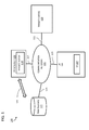
- FIG. 1 provides a schematic block diagram of a communication network system in which TIVM aspects can be provided, according to an embodiment.
- FIG. 2 is a schematic illustration of TIVM components and/or modules, according to an embodiment.
- FIG. 3A is a schematic block diagram illustrating aspects of infrastructure of a threat indicator confirmation system, according to an embodiment.
- FIG. 3B is an example data flow diagram illustrating aspects of interactive data flows between a TIVM server and the affiliated entities, according to an embodiment.
- FIGS. 4A-4C provide example logic flow diagrams illustrating aspects of threat indicator confirmation, according to one embodiment.
- the real-time cyber threat indicator verification mechanism technology may receive, from a host computer, a cyber threat indicator having identifying information of a cyber threat source; instantiate, in response to the cyber threat indicator, a virtual client emulator; send a control message to cause the virtual client emulator to interact with the cyber threat source based on the identifying information; obtain a confidence indicator relating to the cyber threat indicator based on interaction between the virtual client emulator and the cyber threat source; and generate a cyber threat indicator confirmation report including the confidence indicator.
- a real-time cyber threat indicator verification mechanism technology instantiates one or more virtual client emulators to access a source of a threat, in response to a received threat indicator, so as to evaluate validity and/or severity of the potential threat.
- a threat indicator (or an indicator of risk (IoR), as used interchangeably throughout the application) can provide basic context around a cyber threat, and/or behaviors observed or collected by or from a public Internet connected to the target hosts; and such behavioral information may be provided to a user (e.g., a cyber threat analyst, etc.).
- a threat indicator can include, for example, a name of malware, a verbose description of behaviors, a set of IP addresses/Domains/URL identifiers, a set of protocol/port identifiers and various contexts associated with a particular malware instance, and/or the like.
- the TIVM can receive the threat indicators and provide active and real-time verifications of the threat indicators before associating the threat indicators with Internet hosts for further threat processing. In this way, the TIVM can provide users such as cyber analysts with a more accurate and real-time view of those threats, and false alarms of cyber threats will be reduced.
- FIG. 1 provides a schematic block diagram of a communication network system in which TIVM aspects can be provided, according to an embodiment.
- a communication network system 100 can include one or more user devices or user equipments (UEs) 101 , each equipped with at least a user interface (UI) 107 ; one or more TIVM servers 109 ; one or more data source(s) or databases 111 ; and one or more target hosts 108 (e.g., the infected computers, etc.).
- Any of the devices or platforms of the network system 100 can be equipped with local memory/storage spaces (not shown in FIG. 1 ).
- the devices and platforms of the network system 100 may have access to centralized or distributed memory/storage spaces (not shown in FIG. 1 ) through the communication network 105 .
- FIG. 1 is merely an example illustrating the types of devices and platforms that can be included within a communication network system 100 .
- Communication network 105 can be any communication network, such as the Internet, configurable to allow the one or more UEs 101 , the one or more TIVM servers 109 , and the target host(s) 108 to communicate with communication network 105 and/or to each other through communication network 105 .
- Communication network 105 can be any network or combination of networks capable of transmitting information (e.g., data and/or signals) and can include, for example, a telephone network, an Ethernet network, a fiber-optic network, a wireless network, and/or a cellular network.
- communication network 105 can include multiple networks operatively coupled to one another by, for example, network bridges, routers, switches and/or gateways.
- the UEs 101 can be operatively coupled to a cellular network; and the target host(s) 108 can be operatively coupled to a fiber-optic network.
- the cellular network and fiber-optic network can each be operatively coupled to one another via one or more network bridges, routers, switches, and/or gateways such that the cellular network, the Ethernet network and the fiber-optic network are operatively coupled to form a communication network.
- the cellular network and fiber-optic network can each be operatively coupled to one another via one or more additional networks.
- the cellular network and the fiber-optic network can each be operatively coupled to the Internet such that the cellular network, the fiber-optic network and the Internet are operatively coupled to form a communication network.
- UEs 101 are operatively coupled to communication network 105 via network connection(s) 113 ; target host(s) 108 are operatively coupled to communication network 105 via network connection(s) 115 ; TIVM servers 109 are operatively coupled to communication network 105 via network connection(s) 117 ; and data source(s) 111 are operatively coupled to communication network 105 via network connection(s) 119 .
- Network connections 113 , 115 , 117 , and 119 can be any appropriate network connection to operatively couple UEs 101 , target host(s) 108 , the TIVM servers 109 , and the data source(s) 111 .
- the TIVM server(s) 109 can have a direct connection to the data source(s) 111 via communication 121 .
- a network connection can be a wireless network connection such as, for example, a wireless fidelity (“Wi-Fi”) or Wireless Local Area Network (“WLAN”) connection, a Wireless Wide Area Network (“WWAN”) connection, and/or a cellular connection.
- a network connection can be a wired connection such as, for example, an Ethernet connection, a Digital Subscription Line (“DSL”) connection, a broadband coaxial connection, and/or a fiber-optic connection.
- Wi-Fi wireless fidelity
- WLAN Wireless Local Area Network
- WWAN Wireless Wide Area Network
- a network connection can be a wired connection such as, for example, an Ethernet connection, a Digital Subscription Line (“DSL”) connection, a broadband coaxial connection, and/or a fiber-optic connection.
- DSL Digital Subscription Line
- a communication network system 100 can include more than one UE 101 , more than one TIVM server 109 , and more than one data source in.
- a UE 101 , and/or a TIVM server 109 can be operatively coupled to the communication network 105 by heterogeneous network connections.
- a first UE 101 can be operatively coupled to the communication network 105 by a WWAN network connection
- another UE 101 can be operatively coupled to the communication network 105 by a DSL network connection
- a TIVM server 109 can be operatively coupled to the communication network 105 by a fiber-optic network connection.
- the TIVM server(s) 109 each can be, for example, a web server, a remote server, and/or the like, configured to provide search capabilities to electronic devices, such as UEs 101 .
- the UE 101 can be in communication with the TIVM server(s) 109 via the communication network 105 .
- the TIVM server(s) 109 can be a remote server housed separately from the UE 101 .
- the UE 101 can receive a signal representing a report for active confirmation of a cyber threat indicator, from the TIVM server 109 via the communication links 113 and 117 .
- the TIVM server(s) 109 can be integrated with the UE 101 , where the report can be directly presented at the UI 107 on UE 101 .
- the report of active confirmation can be generated at the TIVM server 109 by employing a virtual emulator 114 to access the target host(s) 108 so as to determine whether the target host 108 is infected by any malicious code or program.
- FIG. 2 A detailed discussion of functional module(s) and data store(s) of the TIVM server 109 is provided in FIG. 2 .
- the UEs 101 can be any of a variety of electronic devices that can be operatively coupled to communication network 105 .
- a UE 101 can be, for example, a personal computer, a tablet computer, a personal digital assistant (PDA), a cellular telephone, a portable/mobile internet device, television, kiosk display, display screens in vehicles, projection devices, laser display devices, digital display watches, digital display glasses and/or some other electronic communication device with audio and/or visual capabilities.
- a UE 101 can also be, for example, a television set, a streamer device, a set top box, or any other electronic device equipped with a display unit (a UI 107 ) and a network connection 113 that enables the device to run applications on an operating system.
- the UEs 101 each can include a web browser configured to access a webpage or website, for example, hosted on or accessible via the TIVM platform 103 over communication network 105 .
- the UEs 101 can be, for example, configured to support, for example, Hyper Text Markup Language (HTML) using JavaScript.
- HTML Hyper Text Markup Language
- the UEs 101 can include a web browser, such as, Firefox®, Safari®, Dolphin®, Opera®, Internet Explorer (IE)®, Chrome® and/or similar browsers.
- An Internet page or website can be accessed by a user of a web browser at a UE 101 by providing the web browser with a reference such as a uniform resource locator (URL), for example, of a webpage.
- URL uniform resource locator
- a user of a UE 101 can access a TIVM server 109 via a URL designated for the TIVM server 109 .
- UEs 101 each can include specialized software other than a browser for accessing a web server such as, for example, a TIVM server 109 .
- Specialized software can be, for example, a specialized network-enabled application or program.
- portions of a website accessible via a web server can be located in a local or remote memory space/data store accessible to the web server.
- a UE 101 can also include a display, monitor or user interface (UI) 107 , a keyboard, various ports (e.g., a USB port), and other user interface features, such as, for example, touch screen controls, audio components, and/or video components (each not shown).
- UI monitor or user interface
- the UE 101 may be operated and/or accessed by a user (e.g., a cyber analyst, etc.) to obtain active confirmation report of a threat indicator.
- Data source(s) or database(s) 111 can be distributed sources of data throughout the communication network system 100 .
- a data source 111 can be at least one or more of a database, a data warehouse, a file, etc.
- FIG. 2 is a schematic illustration of TIVM components and/or modules, according to an embodiment.
- the TIVM server 200 can be similar to the TIVM server 109 in FIG. 1 .
- a TIVM server 200 can include a threat indicator module 201 , a virtual client emulator controller module 202 , a TIVM reporting module 203 , and/or the like.
- a data store(s) 211 can include a threat indicator data table 219 a , virtual emulator information data table 219 b , report data table 219 c , and/or the like.
- the TIVM server 200 communicates with other devices of a communication network system (e.g., communication network system 100 of FIG. 1 ) via input signal 221 and output signal 223 .
- a communication network system e.g., communication network system 100 of FIG. 1
- the TIVM server 200 and its components can be located anywhere within a communication network system 100 such as that shown in FIG. 1 including, but not limited to, within the UEs 101 , or in separate locations within the communication network system 100 of FIG. 1 .
- the TIVM server 200 can also be provided as on-premise deployment, via private computation clouds, or be embedded into other software or bundled into devices by Original Equipment Manufacturers (OEMs).
- OEMs Original Equipment Manufacturers
- a module can be, for example, any assembly and/or set of operatively-coupled electrical components, and can include, for example, a memory, a processor, electrical traces, optical connectors, software (executing or to be executed in hardware) and/or the like. Furthermore, a module can be capable of performing one or more specific functions associated with the module, as discussed further below.
- the TIVM server 200 can provide an analytics platform as a Software as a Service (SaaS) such that, for example, the TIVM services are centrally hosted on the information cloud (not shown) for independent software vendors, system integrators, analytics consultants, enterprises, etc., to build multi-tenant business intelligence and embedded analytics solutions for external and internal customers and/or users, for example, by using a browser.
- SaaS Software as a Service
- the TIVM server 200 can enable users to mashup data from various sources for real-time ad-hoc analysis, build reports with rich visualizations and dynamic dashboards, and collaborate in-place among stakeholders to make informed decisions.
- the TIVM server 200 can provide capability of reducing data into smaller parts or views that can yield more information (e.g., slice and dice), drill downs and search on data.
- a multi-dimensional data structure can be considered as a data cube and the act of picking a rectangular subset of a data cube by choosing a single value for one of its dimensions can define a new data cube with one fewer dimension (e.g., slice operation).
- Other operations can produce sub-cubes, for example, by allowing an analyst to pick specific values of multiple dimensions (e.g., dice operation).
- a drill down/up operation allows the user to navigate among levels of data ranging from the most summarized (up) to the most detailed (down).
- the TIVM server 200 can receive an input including a threat indicator sent from a data source (e.g., see 111 in FIG. 1 , etc.) such as a host computer, and the e input signal 221 including the threat indicator may be processed at the threat indicator module 201 ; and the threat indicator can be stored at a threat indicator table 219 a .
- the threat indicator input signal 221 may include a name of malware, or a verbose description of behaviors, a set of IP addresses/Domains/URL identifiers, a set of protocol/port identifiers and various context associated with a particular malware instance, and/or the like. Further detail of the threat indicator module 201 generating an active confirmation list based on the threat indicators is discussed in FIG. 4B and description below.
- the virtual client emulator controller 202 may instantiate one or more client emulator(s) from a virtual emulator information table 219 b to access the IP addresses/Domains/URL identifiers in order to verify the presence of malicious code, collects samples of that malicious code, and determine observable behaviors to increase the overall confidence and knowledge of the reported threat indicator.
- a virtual client emulator can simulate a client terminal and/or a client operational module, such as a client application, a client operating system, a client operation, and/or the like, and send an access request to a threat source based on the IP address/Domain/URL identifier of the threat source, where the access request can be disguised as a request sent from a client terminal.
- the virtual emulator information table 219 b can include data fields such as, but not limited to a virtual emulator identifier, a virtual emulator name, a virtual emulator compatible operating system, a virtual emulator threat type, and/or the like.
- the reported data from the emulators may be integrated in a threat indicator confirmation report at the TIVM reporting module 203 to be stored.
- the output signal 223 may include a variety of data outputs, such as a threat indicator confirmation response (e.g., a confidence indicator of the received threat indicator) from a virtual client emulator, a report of the threat indicator from the report database 219 c , and/or the like.
- a threat indicator confirmation response e.g., a confidence indicator of the received threat indicator
- FIG. 3A is a schematic block diagram illustrating aspects of infrastructure of a threat indicator confirmation system (e.g., a more detailed example illustration of the TIVM server 200 in FIG. 2 ), according to an embodiment.
- the TIVM can include a threat indicator confirmation system 300 that processes a threat indicator received from intelligence feeds 303 a - d , and verifies the threat indicator.
- the threat indicator confirmation system 300 can aggregate a set of threat indicators related to malware and botnets.
- the threat indicator confirmation system 300 can be built as part of a data center 301 , which facilitates the data transmission between various functional modules within the threat indicator confirmation system 300 , such as the data center management 305 , a core intelligence processor 306 , customer management and entitlement module 307 , confirmation controller 321 , confirmation results analyzer 322 , virtual client emulators 324 , and/or the like.
- the data center 301 may also facilitates exogenous data exchange, such as various intelligence feeds 303 a - d to the core intelligence processor 306 , access requests from a virtual client emulator 324 via the Internet 303 to the target host 302 , and/or the like.
- Such data communications can be managed and archived by the data center management module 305 at an archive database 319 a.
- the core intelligence processor 306 can receive various intelligence feeds 303 a - 303 d (e.g., from an internal or external intelligence source, etc.) so that the core intelligence processor 306 can identify the confirmation targets and/or threat indicators.
- the core intelligence processor 306 can then identify the IP addresses and/or the fully qualified domain name (FQDN) of the target hosts 302 from database 319 c , e.g., by forming a query on the database 319 c based on a URL in the threat indicator, etc.
- the IP/FQDN information is passed on to the confirmation controller module 321 , which manages the virtual client emulators 324 , to access a target host(s) 302 via the Internet 303 .
- the confirmation controller module 321 which manages the virtual client emulators 324
- a virtual client emulator can simulate a client terminal and/or client modules to send an access request to the target host( 2 ) 302 .
- the target hosts 302 can interact with the virtual client emulator 324 as if the virtual client emulator 324 is a real client terminal/system, and can send malicious code to the virtual client emulator 324 when the target host(s) 302 includes a cyber threat hazard.
- the virtual client emulator 324 can simulate a web browser running on a client computer, and can generate a simulated Hypertext Transfer Protocol (HTTP) request containing an IP address, a session identifier, a browser identifier, and/or the like to the target host(s) 302 , which can be a web server.
- HTTP Hypertext Transfer Protocol
- the target host(s) 320 When the target host(s) 320 , e.g., the web server, is contaminated with malicious cyber hazards, the target host(s) 302 may respond to the HTTP request with a response (e.g., a connection approval, etc.) but including malicious code, and such malicious code can be captured by the virtual client emulator 342 .
- the virtual client emulator 324 can simulate an electronic mail component, an online gaming component, an instant messaging component, and/or the like.
- the confirmation results obtained by the virtual client emulator(s) 324 may be processed by the confirmation results analyzer 322 .
- the threat indicator confirmation system 300 may provide threat verification service to a customer via the customer management module 307 , which manages customer profiles such as customer identifications and subscriptions information at the database 319 b.
- FIG. 3B is an example data flow diagram illustrating aspects of interactive data flows between a TIVM server (e.g., 109 in FIG. 1 ) and the related entities, according to an embodiment.
- the TIVM server 310 could be similar to the TIVM server 109 in FIG. 1 , and/or the threat indicator confirmation system 300 in FIG. 3A .
- the TIVM server 310 can receive various threat indicators (IoR) 321 a - n from IoR sources 316 a - n .
- IoR threat indicators
- the IoR sources may include a cyber risk monitoring entity, which may be either an automatic system or a manual monitoring mechanism (e.g., a person may manually submit a threat indicator, etc.), and/or the like.
- the TIVM server 310 can instantiate virtual client emulators based on the threat indicator type at 322 .
- a virtual client emulator can correspond to a type of threat indicator, based on criticality, classification, threat indicator source, and/or the like characteristics of the threat indicator.
- a virtual client emulator can correspond to multiple types of threat indicators.
- the client emulators may be housed with the TIVM server 310 , e.g., as shown at 324 in FIG. 3A .
- the client emulators 315 a - n may be distributed emulators that are housed separately from the TIVM server 310 , e.g., as shown at 315 a - n in FIG. 3B .
- a confirmation controller module within the TIVM server 310 (or the threat indicator confirmation system 300 in FIG. 3A ) may distribute the set of source IP addresses or URL identifiers to one or more (virtual) client emulators 315 a - n .
- the client emulators 315 a - n then connect to hosts computers 302 a - n (e.g., the suspected infected computers/devices, etc.), such as compute devices associated with the IP addresses or URLs referenced by the threat indicator, continuously, periodically, intermittently or on an on-demand basis, e.g., by sending access requests 324 a - n to the hosts computers 302 a - n .
- hosts computers 302 a - n e.g., the suspected infected computers/devices, etc.
- compute devices associated with the IP addresses or URLs referenced by the threat indicator continuously, periodically, intermittently or on an on-demand basis, e.g., by sending access requests 324 a - n to the hosts computers 302 a - n .
- each client emulator 315 a - n verifies whether any malicious code is present in the response or active on the host computer; and if there is any, the client emulator 315 a - n collect samples of that malicious code 325 a - n from the received responses or determines observed behavior of the malware running on the host computer.
- the virtual client emulator 315 a - n may then determine a confidence level of the threat indicator (e.g., regarding whether the threat indicator indeed includes a malicious attack, etc.) and send a confidence indicator 326 a - n to the TIVM server 310 .
- the client emulators 315 a - n report back on the collected malicious code 325 a - n to the TIVM server 310 , which may in turn determine whether a malicious attack is indicated with the threat indicator.
- the reporting module (e.g., 203 in FIG. 2 ) can generate a threat indicator confirmation report at 328 .
- Both negative and positive connection and behavior information (e.g., whether the threat indicator corresponds to an actual risk to cyber security, etc.) is included in the threat indicator confirmation report as part of the confirmation data, and is included in the confirmation report.
- the confirmation report can include data fields such as, but not limited to a report name, a report timestamp, a threat indicator identifier, a threat indicator timestamp, a threat IP address, threat FQDN, threat malware type, threat Botnet type, virtual emulator history, a confidence level/indicator, and/or the like.
- FIGS. 4A-4C provide example logic flow diagrams illustrating aspects of threat indicator confirmation (e.g., functions performed by the threat indicator confirmation system 300 in FIG. 3A ), according to one embodiment.
- the TIVM starts with building an active confirmation list of threat indicators to be verified, e.g., at 401 .
- the TIVM can receive a live feed of threat indicator 403 b in real-time, and add the received threat indicator to the active confirmation list.
- the TIVM may process threat indicators offline in a batch, e.g., by obtaining previously received and stored threat indicators (IoRs 402 ) from a data store 403 a.
- IoRs 402 previously received and stored threat indicators
- the active confirmation list 404 can be updated constantly, periodically, intermittently, and/or based on an on-demand basis.
- the VITM can execute the active confirmation list at 405 (as further discussed in FIG. 4C ) to obtain a list of confirmation results 406 , which can be saved at a threat indicator results data store 407 .
- FIG. 4B is a logic flow diagram illustrating aspects of building an active confirmation list (e.g., 401 in FIG. 4A ), according to an embodiment.
- the TIVM can build an active confirmation list based on received threat indicators, for example, by the threat indicator module 201 in FIG. 2 .
- the TIVM upon receiving a threat indicator (or Indicator of Risk (IoR)) at 421 , the TIVM can determine a category of the indicator, e.g., whether it belongs to the malware category at 422 ; if not, whether it belongs to the Botnet category at 423 ; if not, whether it belongs to other advanced persistent threat (APT) categories at 424 , and/or the like.
- IoR Indicator of Risk
- the TIVM can continue to determine whether the threat indicator has a timestamp at 425 . If no timestamp associated with the threat indicator, the TIVM may determine whether the threat indicator has a TIVM timestamp at 426 (e.g., the timestamp added to the indicator when received at the TIVM threat indicator module 201 in FIG. 2 ).
- the TIVM can proceed to determine whether the threat indicator has any associated FQDN at 427 . If no timestamp is associated with the threat indicator, the TIVM may not be able to process the threat indicator, and can move on to the next threat indicator at 421 .
- the TIVM can determine whether the threat indicator has associated IP address at 428 . If neither FQDN is found at 427 , nor is any IP address found at 428 , the TIVM may not be able to process the threat indicator, and can move on to the next threat indicator at 421 . Otherwise, when an IP address is associated with the threat indicator 428 , the TIVM can query a lookup list of FQDN for the IP address using a Power Domain Name Server (pDNS) at 429 , and return the query result of an IP/FQDN list to 430 .
- pDNS Power Domain Name Server
- the TIVM can optionally proceed at 430 , to determine whether the IP address or FQDN is on an exclusion list, e.g., whether the IP or FQDN has been flagged or alerted in previous attack records. If yes, the threat has been confirmed at 430 , and the TIVM can proceed to process the next threat indicator at 421 . If not, the TIVM may add the threat indicator record to an active confirmation list at 431 for further verification, and the TIVM may re-start at 421 to process the next threat indicator.
- an exclusion list e.g., whether the IP or FQDN has been flagged or alerted in previous attack records. If yes, the threat has been confirmed at 430 , and the TIVM can proceed to process the next threat indicator at 421 . If not, the TIVM may add the threat indicator record to an active confirmation list at 431 for further verification, and the TIVM may re-start at 421 to process the next threat indicator.
- an example data structure of the active confirmation record is provided at 432 , including a record identifier, a threat indicator timestamp (determined at 425 ), an optional TIVM timestamp (determined at 426 ), an optional IP address (determined at 428 ), a FQDN list (determined at 427 /429), a Uniform Resource Identifier (URI), and/or the like.
- a threat indicator timestamp determined at 425
- an optional TIVM timestamp determined at 426
- an optional IP address determined at 428
- FQDN list determined at 427 /429
- URI Uniform Resource Identifier
- FIG. 4C is a logic flow diagram illustrating aspects of executing an active confirmation list (e.g., 405 in FIG. 4A ), according to an embodiment.
- the TIVM instantiates an OS virtual machine and produce(s) an active verification request at 413 , e.g., by instantiating a virtual client emulator and facilitating the virtual client emulator to access the IP/URL address of the threat source (see 342 a - n , 325 a - n in FIG. 3B ).
- the TIVM can obtain returned results from the OS virtual machine at 414 , and store such results at an active confirmation job running results database 415 .
- the TIVM can also determine whether all the tests are complete at 416 , e.g., by examining whether all the active confirmation records on the active formation list have been verified. If yes, the TIVM can return the job running results 417 to produce a confirmation report, e.g., at the reporting module 203 in FIG. 2 . Otherwise, the TIVM may continue to examine the remaining active confirmation record at 412 .
- Hardware modules can include, for example, a general-purpose processor, a field programmable gates array (FPGA), and/or an application specific integrated circuit (ASIC).
- Software modules (executed on hardware) can be expressed in a variety of software languages (e.g., computer code), including C, C++, JavaTM, Ruby, Python, JavaScript, Perl, PHP, Visual BasicTM, and other object-oriented, procedural, or other programming language and development tools.
- Examples of computer code include, but are not limited to, micro-code or micro-instructions, machine instructions, such as produced by a compiler, code used to produce a web service, and files containing higher-level instructions that are executed by a computer using an interpreter. Additional examples of computer code include, but are not limited to, control signals, encrypted code, and compressed code.
- Some embodiments described herein relate to a computer storage product with a non-transitory computer-readable medium (also can be referred to as a non-transitory processor-readable medium) having instructions or computer code thereon for performing various computer-implemented operations.
- the computer-readable medium or processor-readable medium
- the media and computer code may be those designed and constructed for the specific purpose or purposes.
- non-transitory computer-readable media include, but are not limited to, magnetic storage media such as hard disks, floppy disks, and magnetic tape; optical storage media such as Compact Disc/Digital Video Discs (CD/DVDs), Compact Disc-Read Only Memories (CD-ROMs), and holographic devices; magneto-optical storage media such as optical disks; carrier wave signal processing modules; and hardware devices that are specially configured to store and execute program code, such as Application-Specific Integrated Circuits (ASICs), Programmable Logic Devices (PLDs), Read-Only Memory (ROM) and Random-Access Memory (RAM) devices.
- ASICs Application-Specific Integrated Circuits
- PLDs Programmable Logic Devices
- ROM Read-Only Memory
- RAM Random-Access Memory
Landscapes
- Engineering & Computer Science (AREA)
- Computer Security & Cryptography (AREA)
- Computer Hardware Design (AREA)
- General Engineering & Computer Science (AREA)
- Theoretical Computer Science (AREA)
- Software Systems (AREA)
- Health & Medical Sciences (AREA)
- General Health & Medical Sciences (AREA)
- Physics & Mathematics (AREA)
- General Physics & Mathematics (AREA)
- Computing Systems (AREA)
- Computer Networks & Wireless Communication (AREA)
- Signal Processing (AREA)
- Virology (AREA)
- Social Psychology (AREA)
- Debugging And Monitoring (AREA)
- Data Exchanges In Wide-Area Networks (AREA)
Abstract
Description
Claims (18)
Priority Applications (2)
| Application Number | Priority Date | Filing Date | Title |
|---|---|---|---|
| US14/339,438 US9596266B1 (en) | 2014-07-23 | 2014-07-23 | Apparatuses, methods and systems for a real-time cyber threat indicator verification mechanism |
| US15/457,403 US10027705B1 (en) | 2014-07-23 | 2017-03-13 | Apparatuses, methods and systems for a real-time cyber threat indicator verification mechanism |
Applications Claiming Priority (1)
| Application Number | Priority Date | Filing Date | Title |
|---|---|---|---|
| US14/339,438 US9596266B1 (en) | 2014-07-23 | 2014-07-23 | Apparatuses, methods and systems for a real-time cyber threat indicator verification mechanism |
Related Child Applications (1)
| Application Number | Title | Priority Date | Filing Date |
|---|---|---|---|
| US15/457,403 Continuation US10027705B1 (en) | 2014-07-23 | 2017-03-13 | Apparatuses, methods and systems for a real-time cyber threat indicator verification mechanism |
Publications (1)
| Publication Number | Publication Date |
|---|---|
| US9596266B1 true US9596266B1 (en) | 2017-03-14 |
Family
ID=58227728
Family Applications (2)
| Application Number | Title | Priority Date | Filing Date |
|---|---|---|---|
| US14/339,438 Active 2034-10-13 US9596266B1 (en) | 2014-07-23 | 2014-07-23 | Apparatuses, methods and systems for a real-time cyber threat indicator verification mechanism |
| US15/457,403 Active US10027705B1 (en) | 2014-07-23 | 2017-03-13 | Apparatuses, methods and systems for a real-time cyber threat indicator verification mechanism |
Family Applications After (1)
| Application Number | Title | Priority Date | Filing Date |
|---|---|---|---|
| US15/457,403 Active US10027705B1 (en) | 2014-07-23 | 2017-03-13 | Apparatuses, methods and systems for a real-time cyber threat indicator verification mechanism |
Country Status (1)
| Country | Link |
|---|---|
| US (2) | US9596266B1 (en) |
Cited By (14)
| Publication number | Priority date | Publication date | Assignee | Title |
|---|---|---|---|---|
| US20160330185A1 (en) * | 2015-05-08 | 2016-11-10 | Cloudflare, Inc. | Generating an NSEC Record |
| US20170149802A1 (en) * | 2015-11-19 | 2017-05-25 | Threat Stream, Inc. | Protecting threat indicators from third party abuse |
| US10033699B2 (en) | 2015-05-08 | 2018-07-24 | Cloudflare, Inc. | Transparent DNSSEC-signing proxy |
| US10230742B2 (en) * | 2015-01-30 | 2019-03-12 | Anomali Incorporated | Space and time efficient threat detection |
| US10242318B2 (en) * | 2016-05-25 | 2019-03-26 | Symantec Corporation | System and method for hierarchical and chained internet security analysis |
| WO2019231826A1 (en) * | 2018-05-28 | 2019-12-05 | RiskLens, Inc. | Systems and methods for determining the efficacy of computer system security policies |
| US11252182B2 (en) * | 2019-05-20 | 2022-02-15 | Cloudflare, Inc. | Identifying malicious client network applications based on network request characteristics |
| US11258828B2 (en) * | 2018-05-28 | 2022-02-22 | RiskLens, Inc. | Systems and methods for monitoring and correcting computer system security practices |
| US20220103596A1 (en) * | 2020-09-28 | 2022-03-31 | T-Mobile Usa, Inc. | Digital on-demand coupons for security service of communications system |
| US11431676B2 (en) * | 2015-12-24 | 2022-08-30 | Huawei Technologies Co., Ltd. | Method, apparatus, and system for detecting terminal security status |
| US11546368B2 (en) | 2020-09-28 | 2023-01-03 | T-Mobile Usa, Inc. | Network security system including a multi-dimensional domain name system to protect against cybersecurity threats |
| US11829484B2 (en) | 2019-11-04 | 2023-11-28 | Monaco Risk Analytics Inc | Cyber risk minimization through quantitative analysis of aggregate control efficacy |
| US20240056482A1 (en) * | 2022-08-09 | 2024-02-15 | Commvault Systems, Inc. | Expedited recovery based on data storage management integration with cyber threat deception |
| CN117834305A (en) * | 2024-03-05 | 2024-04-05 | 米烁网络科技(广州)有限公司 | Network operation environment assessment system based on mimicry security technology |
Families Citing this family (2)
| Publication number | Priority date | Publication date | Assignee | Title |
|---|---|---|---|---|
| CN110677408B (en) * | 2019-07-09 | 2021-07-09 | 腾讯科技(深圳)有限公司 | Attack information processing method and device, storage medium and electronic device |
| US12028214B1 (en) * | 2022-05-26 | 2024-07-02 | Qintel, LLC | Discovering computing entities communicating with a network communication protocol |
Citations (4)
| Publication number | Priority date | Publication date | Assignee | Title |
|---|---|---|---|---|
| US20090307769A1 (en) * | 2006-03-14 | 2009-12-10 | Jon Curnyn | Method and apparatus for providing network security |
| US20120304244A1 (en) * | 2011-05-24 | 2012-11-29 | Palo Alto Networks, Inc. | Malware analysis system |
| US8806646B1 (en) * | 2011-04-27 | 2014-08-12 | Twitter, Inc. | Detecting malware in mobile sites |
| US9003517B2 (en) * | 2009-10-28 | 2015-04-07 | Microsoft Technology Licensing, Llc | Isolation and presentation of untrusted data |
-
2014
- 2014-07-23 US US14/339,438 patent/US9596266B1/en active Active
-
2017
- 2017-03-13 US US15/457,403 patent/US10027705B1/en active Active
Patent Citations (4)
| Publication number | Priority date | Publication date | Assignee | Title |
|---|---|---|---|---|
| US20090307769A1 (en) * | 2006-03-14 | 2009-12-10 | Jon Curnyn | Method and apparatus for providing network security |
| US9003517B2 (en) * | 2009-10-28 | 2015-04-07 | Microsoft Technology Licensing, Llc | Isolation and presentation of untrusted data |
| US8806646B1 (en) * | 2011-04-27 | 2014-08-12 | Twitter, Inc. | Detecting malware in mobile sites |
| US20120304244A1 (en) * | 2011-05-24 | 2012-11-29 | Palo Alto Networks, Inc. | Malware analysis system |
Cited By (22)
| Publication number | Priority date | Publication date | Assignee | Title |
|---|---|---|---|---|
| US10230742B2 (en) * | 2015-01-30 | 2019-03-12 | Anomali Incorporated | Space and time efficient threat detection |
| US10616248B2 (en) | 2015-01-30 | 2020-04-07 | Anomali Incorporated | Space and time efficient threat detection |
| US20160330185A1 (en) * | 2015-05-08 | 2016-11-10 | Cloudflare, Inc. | Generating an NSEC Record |
| US9954840B2 (en) * | 2015-05-08 | 2018-04-24 | Cloudflare, Inc. | Generating a negative answer to a domain name system query that indicates resource records as existing for the domain name regardless of whether those resource records actually exist for the domain name |
| US10033699B2 (en) | 2015-05-08 | 2018-07-24 | Cloudflare, Inc. | Transparent DNSSEC-signing proxy |
| US11647008B2 (en) | 2015-05-08 | 2023-05-09 | Cloudflare, Inc. | Generating a negative answer to a domain name system query that indicates resource records as existing for the domain name regardless of whether those resource records actually exist |
| US20170149802A1 (en) * | 2015-11-19 | 2017-05-25 | Threat Stream, Inc. | Protecting threat indicators from third party abuse |
| US10367829B2 (en) * | 2015-11-19 | 2019-07-30 | Anomali Incorporated | Protecting threat indicators from third party abuse |
| US11431676B2 (en) * | 2015-12-24 | 2022-08-30 | Huawei Technologies Co., Ltd. | Method, apparatus, and system for detecting terminal security status |
| US10242318B2 (en) * | 2016-05-25 | 2019-03-26 | Symantec Corporation | System and method for hierarchical and chained internet security analysis |
| US11258828B2 (en) * | 2018-05-28 | 2022-02-22 | RiskLens, Inc. | Systems and methods for monitoring and correcting computer system security practices |
| WO2019231826A1 (en) * | 2018-05-28 | 2019-12-05 | RiskLens, Inc. | Systems and methods for determining the efficacy of computer system security policies |
| US11252182B2 (en) * | 2019-05-20 | 2022-02-15 | Cloudflare, Inc. | Identifying malicious client network applications based on network request characteristics |
| US11829484B2 (en) | 2019-11-04 | 2023-11-28 | Monaco Risk Analytics Inc | Cyber risk minimization through quantitative analysis of aggregate control efficacy |
| US20220103596A1 (en) * | 2020-09-28 | 2022-03-31 | T-Mobile Usa, Inc. | Digital on-demand coupons for security service of communications system |
| US11496522B2 (en) * | 2020-09-28 | 2022-11-08 | T-Mobile Usa, Inc. | Digital on-demand coupons for security service of communications system |
| US11546368B2 (en) | 2020-09-28 | 2023-01-03 | T-Mobile Usa, Inc. | Network security system including a multi-dimensional domain name system to protect against cybersecurity threats |
| US20230034908A1 (en) * | 2020-09-28 | 2023-02-02 | T-Mobile Usa, Inc. | Digital coupons for security service of communications system |
| US12074899B2 (en) | 2020-09-28 | 2024-08-27 | T-Mobile Usa, Inc. | Network security system including a multi-dimensional domain name system to protect against cybersecurity threats |
| US20240056482A1 (en) * | 2022-08-09 | 2024-02-15 | Commvault Systems, Inc. | Expedited recovery based on data storage management integration with cyber threat deception |
| CN117834305A (en) * | 2024-03-05 | 2024-04-05 | 米烁网络科技(广州)有限公司 | Network operation environment assessment system based on mimicry security technology |
| CN117834305B (en) * | 2024-03-05 | 2024-05-10 | 米烁网络科技(广州)有限公司 | Network operation environment assessment system based on mimicry security technology |
Also Published As
| Publication number | Publication date |
|---|---|
| US10027705B1 (en) | 2018-07-17 |
Similar Documents
| Publication | Publication Date | Title |
|---|---|---|
| US10027705B1 (en) | Apparatuses, methods and systems for a real-time cyber threat indicator verification mechanism | |
| US11757945B2 (en) | Collaborative database and reputation management in adversarial information environments | |
| US11924251B2 (en) | System and method for cybersecurity reconnaissance, analysis, and score generation using distributed systems | |
| US11025674B2 (en) | Cybersecurity profiling and rating using active and passive external reconnaissance | |
| US20220014560A1 (en) | Correlating network event anomalies using active and passive external reconnaissance to identify attack information | |
| US9213832B2 (en) | Dynamically scanning a web application through use of web traffic information | |
| JP6608948B2 (en) | Network flow log for multi-tenant environments | |
| US20220201042A1 (en) | Ai-driven defensive penetration test analysis and recommendation system | |
| US9118714B1 (en) | Apparatuses, methods and systems for a cyber threat visualization and editing user interface | |
| US10795991B1 (en) | Enterprise search | |
| US9584541B1 (en) | Cyber threat identification and analytics apparatuses, methods and systems | |
| US20160080408A1 (en) | Apparatuses, methods and systems for a cyber security assessment mechanism | |
| US8561187B1 (en) | System and method for prosecuting dangerous IP addresses on the internet | |
| US11647037B2 (en) | Penetration tests of systems under test | |
| US20220109685A1 (en) | Network device identification via similarity of operation and auto-labeling | |
| US20240291870A1 (en) | Automatically computing and improving a cybersecurity risk score | |
| US20220414206A1 (en) | Browser extension for cybersecurity threat intelligence and response | |
| US11968239B2 (en) | System and method for detection and mitigation of data source compromises in adversarial information environments | |
| US20240244090A1 (en) | Cybersecurity analysis and protection using distributed systems | |
| CN111104675A (en) | Method and device for detecting system security vulnerability | |
| CN110545277B (en) | Risk processing method and device applied to security system, computing equipment and medium | |
| US20230283641A1 (en) | Dynamic cybersecurity scoring using traffic fingerprinting and risk score improvement | |
| CN112822147A (en) | Method, system and equipment for analyzing attack chain | |
| WO2021243321A1 (en) | A system and methods for score cybersecurity | |
| US11985144B2 (en) | Browser extension for cybersecurity threat intelligence and response |
Legal Events
| Date | Code | Title | Description |
|---|---|---|---|
| AS | Assignment |
Owner name: LOOKINGGLASS CYBER SOLUTIONS, INC., MARYLAND Free format text: ASSIGNMENT OF ASSIGNORS INTEREST;ASSIGNORS:COLEMAN, CHRISTOPHER D.;THOMSON, ALLAN;LEWIS, JASON A.;SIGNING DATES FROM 20150901 TO 20160628;REEL/FRAME:039031/0378 |
|
| STCF | Information on status: patent grant |
Free format text: PATENTED CASE |
|
| CC | Certificate of correction | ||
| MAFP | Maintenance fee payment |
Free format text: PAYMENT OF MAINTENANCE FEE, 4TH YR, SMALL ENTITY (ORIGINAL EVENT CODE: M2551); ENTITY STATUS OF PATENT OWNER: SMALL ENTITY Year of fee payment: 4 |
|
| AS | Assignment |
Owner name: EASTWARD FUND MANAGEMENT, MASSACHUSETTS Free format text: SECURITY INTEREST;ASSIGNOR:LOOKINGGLASS CYBER SOLUTIONS, INC.;REEL/FRAME:056822/0787 Effective date: 20210625 |
|
| AS | Assignment |
Owner name: SILICON VALLEY BANK, CALIFORNIA Free format text: SECURITY INTEREST;ASSIGNOR:LOOKINGGLASS CYBER SOLUTIONS, INC.;REEL/FRAME:057275/0234 Effective date: 20210824 |
|
| AS | Assignment |
Owner name: EASTWARD FUND MANAGEMENT, LLC, MASSACHUSETTS Free format text: SECURITY INTEREST;ASSIGNOR:LOOKINGGLASS CYBER SOLUTIONS, INC.;REEL/FRAME:059892/0264 Effective date: 20220510 |
|
| AS | Assignment |
Owner name: LOOKINGGLASS CYBER SOLUTIONS, INC., VIRGINIA Free format text: RELEASE BY SECURED PARTY;ASSIGNOR:SILICON VALLEY BANK;REEL/FRAME:062871/0797 Effective date: 20230301 |
|
| AS | Assignment |
Owner name: LOOKINGGLASS CYBER SOLUTIONS, LLC, VIRGINIA Free format text: CHANGE OF NAME;ASSIGNOR:LOOKINGGLASS CYBER SOLUTIONS, INC.;REEL/FRAME:063821/0591 Effective date: 20230419 Owner name: STIFEL BANK, MISSOURI Free format text: SECURITY INTEREST;ASSIGNOR:LOOKINGGLASS CYBER SOLUTIONS, LLC;REEL/FRAME:063829/0248 Effective date: 20230531 |
|
| AS | Assignment |
Owner name: CYVEILLANCE, INC., VIRGINIA Free format text: RELEASE BY SECURED PARTY;ASSIGNOR:EASTWARD FUND MANAGEMENT, LLC;REEL/FRAME:067131/0715 Effective date: 20230421 Owner name: CLOUDSHIELD TECHNOLOGIES, LLC, VIRGINIA Free format text: RELEASE BY SECURED PARTY;ASSIGNOR:EASTWARD FUND MANAGEMENT, LLC;REEL/FRAME:067131/0715 Effective date: 20230421 Owner name: LOOKINGGLASS CYBER SOLUTIONS, INC., VIRGINIA Free format text: RELEASE BY SECURED PARTY;ASSIGNOR:EASTWARD FUND MANAGEMENT, LLC;REEL/FRAME:067131/0715 Effective date: 20230421 Owner name: CYVEILLANCE, INC., VIRGINIA Free format text: RELEASE BY SECURED PARTY;ASSIGNOR:EASTWARD FUND MANAGEMENT, LLC;REEL/FRAME:067131/0803 Effective date: 20230421 Owner name: CLOUDSHIELD TECHNOLOGIES, LLC, VIRGINIA Free format text: RELEASE BY SECURED PARTY;ASSIGNOR:EASTWARD FUND MANAGEMENT, LLC;REEL/FRAME:067131/0803 Effective date: 20230421 Owner name: LOOKINGGLASS CYBER SOLUTIONS, INC., VIRGINIA Free format text: RELEASE BY SECURED PARTY;ASSIGNOR:EASTWARD FUND MANAGEMENT, LLC;REEL/FRAME:067131/0803 Effective date: 20230421 |
|
| AS | Assignment |
Owner name: MONROE CAPITAL MANAGEMENT ADVISORS, LLC, ILLINOIS Free format text: SECURITY INTEREST;ASSIGNORS:ZEROFOX, INC.;LOOKINGGLASS CYBER SOLUTIONS, LLC;IDENTITY THEFT GUARD SOLUTIONS, INC.;REEL/FRAME:067396/0304 Effective date: 20240513 |
|
| AS | Assignment |
Owner name: LOOKINGGLASS CYBER SOLUTIONS, LLC, MARYLAND Free format text: RELEASE BY SECURED PARTY;ASSIGNOR:STIFEL BANK;REEL/FRAME:067429/0361 Effective date: 20240513 |
|
| MAFP | Maintenance fee payment |
Free format text: PAYMENT OF MAINTENANCE FEE, 8TH YR, SMALL ENTITY (ORIGINAL EVENT CODE: M2552); ENTITY STATUS OF PATENT OWNER: SMALL ENTITY Year of fee payment: 8 |