US9595726B2 - Fuel reforming system and process - Google Patents
Fuel reforming system and process Download PDFInfo
- Publication number
- US9595726B2 US9595726B2 US14/148,971 US201414148971A US9595726B2 US 9595726 B2 US9595726 B2 US 9595726B2 US 201414148971 A US201414148971 A US 201414148971A US 9595726 B2 US9595726 B2 US 9595726B2
- Authority
- US
- United States
- Prior art keywords
- fuel
- path
- reformate
- reformates
- spiral
- Prior art date
- Legal status (The legal status is an assumption and is not a legal conclusion. Google has not performed a legal analysis and makes no representation as to the accuracy of the status listed.)
- Active, expires
Links
Images



Classifications
-
- H—ELECTRICITY
- H01—ELECTRIC ELEMENTS
- H01M—PROCESSES OR MEANS, e.g. BATTERIES, FOR THE DIRECT CONVERSION OF CHEMICAL ENERGY INTO ELECTRICAL ENERGY
- H01M8/00—Fuel cells; Manufacture thereof
- H01M8/06—Combination of fuel cells with means for production of reactants or for treatment of residues
- H01M8/0606—Combination of fuel cells with means for production of reactants or for treatment of residues with means for production of gaseous reactants
- H01M8/0612—Combination of fuel cells with means for production of reactants or for treatment of residues with means for production of gaseous reactants from carbon-containing material
- H01M8/0618—Reforming processes, e.g. autothermal, partial oxidation or steam reforming
-
- C—CHEMISTRY; METALLURGY
- C01—INORGANIC CHEMISTRY
- C01B—NON-METALLIC ELEMENTS; COMPOUNDS THEREOF; METALLOIDS OR COMPOUNDS THEREOF NOT COVERED BY SUBCLASS C01C
- C01B3/00—Hydrogen; Gaseous mixtures containing hydrogen; Separation of hydrogen from mixtures containing it; Purification of hydrogen; Reversible storage of hydrogen
- C01B3/02—Production of hydrogen; Production of gaseous mixtures containing hydrogen
- C01B3/32—Production of hydrogen; Production of gaseous mixtures containing hydrogen by reaction of gaseous or liquid organic compounds with gasifying agents, e.g. water, carbon dioxide or air
- C01B3/34—Production of hydrogen; Production of gaseous mixtures containing hydrogen by reaction of gaseous or liquid organic compounds with gasifying agents, e.g. water, carbon dioxide or air by reaction of hydrocarbons with gasifying agents
- C01B3/36—Production of hydrogen; Production of gaseous mixtures containing hydrogen by reaction of gaseous or liquid organic compounds with gasifying agents, e.g. water, carbon dioxide or air by reaction of hydrocarbons with gasifying agents using oxygen; using mixtures containing oxygen as gasifying agents
-
- C—CHEMISTRY; METALLURGY
- C01—INORGANIC CHEMISTRY
- C01B—NON-METALLIC ELEMENTS; COMPOUNDS THEREOF; METALLOIDS OR COMPOUNDS THEREOF NOT COVERED BY SUBCLASS C01C
- C01B2203/00—Integrated processes for the production of hydrogen or synthesis gas
- C01B2203/02—Processes for making hydrogen or synthesis gas
- C01B2203/025—Processes for making hydrogen or synthesis gas containing a partial oxidation step
- C01B2203/0255—Processes for making hydrogen or synthesis gas containing a partial oxidation step containing a non-catalytic partial oxidation step
-
- C—CHEMISTRY; METALLURGY
- C01—INORGANIC CHEMISTRY
- C01B—NON-METALLIC ELEMENTS; COMPOUNDS THEREOF; METALLOIDS OR COMPOUNDS THEREOF NOT COVERED BY SUBCLASS C01C
- C01B2203/00—Integrated processes for the production of hydrogen or synthesis gas
- C01B2203/02—Processes for making hydrogen or synthesis gas
- C01B2203/0283—Processes for making hydrogen or synthesis gas containing a CO-shift step, i.e. a water gas shift step
-
- C—CHEMISTRY; METALLURGY
- C01—INORGANIC CHEMISTRY
- C01B—NON-METALLIC ELEMENTS; COMPOUNDS THEREOF; METALLOIDS OR COMPOUNDS THEREOF NOT COVERED BY SUBCLASS C01C
- C01B2203/00—Integrated processes for the production of hydrogen or synthesis gas
- C01B2203/06—Integration with other chemical processes
- C01B2203/062—Hydrocarbon production, e.g. Fischer-Tropsch process
-
- C—CHEMISTRY; METALLURGY
- C01—INORGANIC CHEMISTRY
- C01B—NON-METALLIC ELEMENTS; COMPOUNDS THEREOF; METALLOIDS OR COMPOUNDS THEREOF NOT COVERED BY SUBCLASS C01C
- C01B2203/00—Integrated processes for the production of hydrogen or synthesis gas
- C01B2203/06—Integration with other chemical processes
- C01B2203/066—Integration with other chemical processes with fuel cells
-
- C—CHEMISTRY; METALLURGY
- C01—INORGANIC CHEMISTRY
- C01B—NON-METALLIC ELEMENTS; COMPOUNDS THEREOF; METALLOIDS OR COMPOUNDS THEREOF NOT COVERED BY SUBCLASS C01C
- C01B2203/00—Integrated processes for the production of hydrogen or synthesis gas
- C01B2203/08—Methods of heating or cooling
- C01B2203/0872—Methods of cooling
- C01B2203/0883—Methods of cooling by indirect heat exchange
-
- C—CHEMISTRY; METALLURGY
- C01—INORGANIC CHEMISTRY
- C01B—NON-METALLIC ELEMENTS; COMPOUNDS THEREOF; METALLOIDS OR COMPOUNDS THEREOF NOT COVERED BY SUBCLASS C01C
- C01B2203/00—Integrated processes for the production of hydrogen or synthesis gas
- C01B2203/12—Feeding the process for making hydrogen or synthesis gas
- C01B2203/1205—Composition of the feed
- C01B2203/1211—Organic compounds or organic mixtures used in the process for making hydrogen or synthesis gas
- C01B2203/1235—Hydrocarbons
-
- C—CHEMISTRY; METALLURGY
- C01—INORGANIC CHEMISTRY
- C01B—NON-METALLIC ELEMENTS; COMPOUNDS THEREOF; METALLOIDS OR COMPOUNDS THEREOF NOT COVERED BY SUBCLASS C01C
- C01B2203/00—Integrated processes for the production of hydrogen or synthesis gas
- C01B2203/12—Feeding the process for making hydrogen or synthesis gas
- C01B2203/1205—Composition of the feed
- C01B2203/1211—Organic compounds or organic mixtures used in the process for making hydrogen or synthesis gas
- C01B2203/1235—Hydrocarbons
- C01B2203/1241—Natural gas or methane
-
- C—CHEMISTRY; METALLURGY
- C01—INORGANIC CHEMISTRY
- C01B—NON-METALLIC ELEMENTS; COMPOUNDS THEREOF; METALLOIDS OR COMPOUNDS THEREOF NOT COVERED BY SUBCLASS C01C
- C01B2203/00—Integrated processes for the production of hydrogen or synthesis gas
- C01B2203/12—Feeding the process for making hydrogen or synthesis gas
- C01B2203/1205—Composition of the feed
- C01B2203/1211—Organic compounds or organic mixtures used in the process for making hydrogen or synthesis gas
- C01B2203/1235—Hydrocarbons
- C01B2203/1247—Higher hydrocarbons
-
- Y—GENERAL TAGGING OF NEW TECHNOLOGICAL DEVELOPMENTS; GENERAL TAGGING OF CROSS-SECTIONAL TECHNOLOGIES SPANNING OVER SEVERAL SECTIONS OF THE IPC; TECHNICAL SUBJECTS COVERED BY FORMER USPC CROSS-REFERENCE ART COLLECTIONS [XRACs] AND DIGESTS
- Y02—TECHNOLOGIES OR APPLICATIONS FOR MITIGATION OR ADAPTATION AGAINST CLIMATE CHANGE
- Y02E—REDUCTION OF GREENHOUSE GAS [GHG] EMISSIONS, RELATED TO ENERGY GENERATION, TRANSMISSION OR DISTRIBUTION
- Y02E60/00—Enabling technologies; Technologies with a potential or indirect contribution to GHG emissions mitigation
- Y02E60/30—Hydrogen technology
- Y02E60/50—Fuel cells
Definitions
- the present invention is directed to fuel reforming processes and systems. More particularly, the present invention is directed to fuel reforming processes and systems receiving hydrocarbon-air mixtures in fuel-rich conditions.
- Electrical power generation devices using hydrocarbons such as natural gas, gasoline, diesel, military logistic fuels, and other similar materials as the energy storage medium have several advantages over batteries. Such advantages include, for example, higher energy density, easier transportation, operation with a variety of supply infrastructures, short recharge periods, and other benefits.
- Some devices operate using syngas, a mixture of H 2 and CO.
- Syngas having H 2 and CO can be produced from hydrocarbons by using catalysts in fuel reformers.
- Using the catalysts permits a rapid reaction rate for fuel-rich reaction that has lower reaction temperature.
- the catalysts lower the effective activation energy so that products are able to reach their chemical equilibrium state at reduced temperatures resulting in near-theoretical yields (maximum amounts attainable) of H 2 and CO in the syngas.
- sulfur compounds and/or higher hydrocarbons present in the energy storage medium can easily poison or deposit carbon (coking) on the catalyst, which degrades performance and shortens the useful life of the catalyst for reformer operations. Catalysts also suffer from other deactivation mechanisms such as sintering.
- syngas having H 2 and CO can also be generated in fuel-rich reaction at elevated temperature, for example, using pure oxygen instead of air as oxidizer to reduce the need for thermal diluents or using an external energy source (for example, plasma) to provide excess energy in the reactants and thus accelerate the reaction rate.
- an external energy source for example, plasma
- a known combustor operates with a combustion zone configured for receiving fuel-lean energy storage media from a first spiraling path in a spiral heat exchanger to produce combustion products.
- the combustion products include H 2 O and CO 2 , which are expelled through a second spiraling path and preheat the incoming reactants in the first spiraling path.
- the known combustor is able to create a higher temperature reaction zone using air as oxidizer without external energy input, but the combustion products are not capable of being used in systems and processes requiring a syngas with a higher concentration of H 2 and CO than the resulting effluent from combustion.
- Fuel reforming processes and systems that produce one or more improvements would be desirable in the art.
- a fuel reforming process includes providing a fuel reformer, the fuel reformer including a reaction zone configured for exothermic partial oxidation to generate reformates and a heat exchanger extending from the reaction zone, the heat exchanger configured to expel the reformates through a reformate path and receive fuel-rich reactants through a fuel path.
- the fuel reforming process also includes generating the reformates by the exothermic partial oxidation of the fuel-rich reactants within the reaction zone and heating the fuel-rich reactants with the heat exchanger by heat from the reformates in the reformate path. The process is energetically self-sustained and operates without a catalyst.
- a fuel reforming system in another exemplary embodiment, includes a fuel reformer, the fuel reformer comprising a reaction zone configured for exothermic partial oxidation to generate reformates and a spiral heat exchanger extending from the reaction zone, the spiral heat exchanger configured to expel the reformates through a first spiraling path and receive fuel-rich reactants through a second spiraling path, and a fuel cell arranged and disposed to receive the reformates from the fuel reformer.
- a fuel reforming system in another exemplary embodiment, includes a fuel reformer, the fuel reformer comprising a reaction zone configured for exothermic partial oxidation to generate reformates, and a spiral heat exchanger extending from the reaction zone, the spiral heat exchanger configured to expel the reformates through a first spiraling path and receive fuel-rich reactants through a second spiraling path, and a component capable of operation with the reformates and incompatible with combustion products.
- FIG. 1 is a schematic view of a fuel reformer with a spiral arrangement during a fuel reforming process, according to an embodiment of the disclosure.
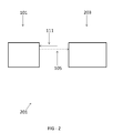
- FIG. 2 is a schematic view of a system having a fuel reformer and a secondary device, according to an embodiment of the disclosure.
- FIG. 3 is a schematic view of a fuel reformer with a toroidal arrangement, according to an embodiment of the disclosure.
- FIG. 4 is a schematic view of a fuel reformer with a square spiral arrangement, according to an embodiment of the disclosure.
- Embodiments of the present disclosure permit higher energy density, permit easier transportation, permit intermittent or continuous operation utilizing existing supply infrastructures, increase yields of H 2 and CO in syngas without catalysts, reduce or eliminate coking and/or catalyst degradation, have a longer operational life, operate without noble-metal-based catalysts (such as rhodium), are less complicated, operate without sub-systems (for example, pre-desulfurization, water management, and/or complicated control sub-systems), are portable, are smaller, are energetically self-sufficient, operate without pure oxygen streams, operate with fuel-rich combustion products, permit lower pressure drops (thus requiring less pump power), other suitable distinctions, or a combination thereof.
- noble-metal-based catalysts such as rhodium
- sub-systems for example, pre-desulfurization, water management, and/or complicated control sub-systems
- are portable are smaller, are energetically self-sufficient, operate without pure oxygen streams, operate with fuel-rich combustion products, permit lower pressure drops (thus requiring less pump power), other suitable
- FIG. 1 shows an embodiment of a fuel reformer 101 during an embodiment of a fuel reforming process.
- the fuel reformer 101 includes a reaction zone 103 configured for exothermic partial oxidation of fuel-rich reactants 111 .
- the reaction zone 103 is arranged and disposed within the fuel reformer 101 , for example, in the middle or substantially in the middle of the fuel reformer 101 .
- the reaction zone 103 is defined by internal structures (not shown) and/or elements of one or more features described hereinafter.
- the reaction zone 103 includes any suitable features permitting operation at high temperatures and/or under-oxidizing conditions.
- partial oxidation refers to a chemical reaction that occurs in oxygen-deficient conditions (with equivalence ration being greater than 1), such as, when a fuel-air or fuel-oxygen mixture is partially reacted to produce H 2 and CO.
- An embodiment of the reforming process using the fuel reformer 101 operates energetically self-sustained and without a catalyst by generating reformates 105 by the exothermic partial oxidation process, while heating the fuel-rich reactants 111 upstream of the reaction zone 103 , for example, with a heat exchanger, that efficiently transfers heat from the reformates 105 in the reformate path 109 to the fuel-rich reactants 111 flowing in adjacent spiral windings (for example, to an adiabatic flame temperature, a super-adiabatic flame temperature, or at least to an adiabatic flame temperature or a super-adiabatic flame temperature).
- the fuel reformer 101 and/or one or more components within the fuel reformer 101 are fabricated from any material capable of handling the operational conditions. Such materials include, but are not limited to, stainless steel and nickel-based superalloys.
- a fuel path 113 and a reformate path 109 extend from the reaction zone 103 , for example, in a spiraling countercurrent arrangement.
- the merger of the fuel path 113 and the reformate path 109 define the reaction zone 103 .
- one or both of the fuel path 113 and the reformate path 109 spiral from the reaction zone 103 , for example, along a spiral heat exchanger 107 .
- the spiral nature of the spiral heat exchanger 107 includes any suitable arrangement with complete or partial overlapping of the fuel path 113 and the reformate path 109 that permits separate fluid transport. Suitable arrangements include, but are not limited to, an arrangement of two or more plates coiled to form a spiral as is shown in FIG.
- the spiral heat exchanger 107 includes one or more heat transfer enhancements, for example, as occur naturally (Dean vortices) and/or through including additional inserts or other heat transfer enhancements to increase heat transfer and/or enable the reformate path 109 and/or the fuel path 113 to maintain a desired heat transfer rate.
- the spiral arrangement includes any suitable dimensions and/or configuration.
- the spiral arrangement includes any suitable number of turns, which are substantially extensions around the reaction zone 103 .
- Suitable numbers of turns include, but are not limited to, 3 or more turns, 6 or more turns, between 3 and 10 turns, between 3 and 12 turns, between 6 and 12 turns, between 10 and 12 turns, between 3 and 16 turns, between 6 and 16 turns, between 10 and 16 turns, 6 or more turns, 10 or more turns, 12 or more turns, 16 or more turns, or any suitable combination, sub-combination, range, or sub-range therein.
- the spiral arrangement includes any suitable separation for the fuel path 113 and/or the reformate path 109 .
- the fuel path 113 and/or the reformate path 109 have a thickness within one or more of the turns of between 2 mm and 3 mm, between 1 mm and 5 mm, between 1 mm and 4 mm, between 2 mm and 5 mm, 2 mm, 2.5 mm, 3 mm, or any suitable combination, sub-combination, range, or sub-range therein.
- the fuel path 113 and/or the reformate path 109 increase in width consistent with increased pressure regions.
- the spiral arrangement also includes any suitable dimensions for the axial length of the fuel path 113 and/or the reformate path 109 .
- Suitable dimensions include, but are not limited to, between 10 mm and 100 mm, between 20 mm and 80 mm, between 30 mm and 70 mm, between 40 mm and 60 mm, between 45 mm and 55 mm, 45 mm, 50 mm, 55 mm, or any suitable combination, sub-combination, range, or sub-range therein.
- the reaction zone 103 extends axially along the region between the fuel path 113 and the reformate path 109 , which provides greater heat release to loss (through end plates) ratio and, therefore, more heat recirculation effect.
- the spiral arrangement produces multiple heat transfer benefits.
- the spiral arrangement increases a heat transfer effect, for example, through centrifugal instability that occurs within the spiral channel.
- the spiral arrangement provides a larger ratio of heat exchange area to heat loss area, thereby increasing exchanger efficiency for a defined volume, in comparison to non-spiraling arrangements.
- the configuration of the arrangement and/or the number of the turns is selected to correspond to such properties.
- the reaction zone 103 generates the reformates 105 from the exothermic partial oxidation of the fuel-rich reactants 111 provided via the fuel path 113 .
- the fuel-rich reactants 111 have any suitable composition capable of producing a greater stoichiometric amount of H 2 during the exothermic partial oxidation of the fuel reforming process, for example, in comparison to complete combustion processes. Additionally or alternatively, the fuel-rich reactants 111 have any suitable composition capable of producing a greater stoichiometric amount of CO during the exothermic partial oxidation of the fuel reforming process, for example, in comparison to combustion processes.
- Suitable compositions of the fuel-rich reactants 111 include, but are not limited to, propane-air mixtures (for example, at an equivalence ratio equal to 3), vaporized liquid fuel-air mixtures (for example, n-heptane, kerosene-based fuel, and/or Jet Propellant 8 jet fuel), pulverized solid fuel-air mixtures (for example, coal-air, and/or biomass-air mixtures), or a combination thereof.
- propane-air mixtures for example, at an equivalence ratio equal to 3
- vaporized liquid fuel-air mixtures for example, n-heptane, kerosene-based fuel, and/or Jet Propellant 8 jet fuel
- pulverized solid fuel-air mixtures for example, coal-air, and/or biomass-air mixtures
- the reformates 105 transfer heat, generated from the exothermic partial oxidation, to the fuel rich reactants 111 , the fuel path 113 , and/or the spiral heat exchanger 107 .
- the heat is transferred by the reformate path 109 being in contact with the fuel path 113 and/or the spiral heat exchanger 107 .
- the transfer of the heat permits a high reaction temperature resulting a fast reaction rate and the fuel reforming process to be energetically self-sustained and/or operate without a catalyst.
- the fuel-rich reactants 111 and/or the fuel path 113 are at a lowest temperature (for example, ambient temperature) upon entry to the fuel reformer 101 .
- the temperature of the fuel-rich reactants 111 and/or the fuel path 113 increase in temperature via heat recirculation along the direction of flow until reaching the reaction zone 103 and then the exothermic partial oxidation further increases the temperature to the highest temperature (for example, between 1000° C. and 1300° C., the adiabatic flame temperature for equivalence ratio equal to 3 of propane-air mixture is 808° C.) at or near the reaction zone 103 .
- the reformates 105 travel from the reaction zone 103 through the reformate path 109 .
- the reformate path 109 and the reformates 105 are at a highest temperature (for example, between 1000° C. and 1300° C.) at the reaction zone 103 and decrease in temperature along the direction of flow until reaching a lower temperature upon flowing from the fuel reformer 101 .
- the composition of the reformates 105 and the arrangement of the fuel path 113 and the reformate path 109 permit the fuel reformer 101 to be used in conjunction with systems incompatible with combustors.
- being “incompatible with combustors” refers to not being operable when receiving combustion products.
- the fuel reformer 101 is arranged within a system 201 having a component 203 or device capable of use or operation with the reformates 105 .
- the component 203 is a fuel cell (for example, a solid oxide fuel cell, a 250 W fuel cell, a fuel cell having less than 500 W power, or any other suitable fuel cell), a hydrogen and/or syngas storage container, a hydrogen separation unit, an auxiliary power unit, a portable power generation system, a micro-combined heat and power system (m-CHP), a robotic system, another suitable apparatus, an after-treatment system in a diesel engine (for example, to reform part of diesel to syngas and regenerate lean NOx catalyst), a gasoline engine, or a combination thereof.
- a fuel cell for example, a solid oxide fuel cell, a 250 W fuel cell, a fuel cell having less than 500 W power, or any other suitable fuel cell
- a hydrogen and/or syngas storage container for example, a solid oxide fuel cell, a 250 W fuel cell, a fuel cell having less than 500 W power, or any other suitable fuel cell
- a hydrogen and/or syngas storage container for example, a hydrogen and/or syngas storage container
- Other devices include, but are not limited to, a water gas shift reactor having water introduced or produced, the water reacting with CO(g) in the reformate to produce additional H 2 by the equation CO+H 2 O ⁇ CO 2 +H 2 and/or a Fischer-Tropsch reactor having a Fischer-Tropsch catalyst to synthesize liquid fuels.
- the system 201 is or includes any arrangement including the fuel reformer 101 and the component 203 , such as, a power generation system, a reactor, a diesel engine, a gasoline engine, a vehicle, an independently-powered device, or a combination thereof.
- the fuel reformer 101 is separate from other portions of the system 201 and the reformates 105 are transported to the other portions of the system 201 .
- the system 201 includes any suitable features for operating the fuel reformer 101 in conjunction with the reformates 105 .
- Suitable features include, but are not limited to, a blower (not shown) and a fuel injection system (not shown).
- additional sub-systems for example, pre-desulfurization, water management, inert gas protection for start-up and shut-down, and/or complicated control sub-systems are not utilized.
- the fuel reformer 101 and/or the system 201 are capable of being adjusted to increase the concentration of H 2 and/or CO in the process, for example, achieving a mixture having a concentration of H 2 and CO that is at or near their thermodynamic equilibrium concentrations.
- Achievable molar concentrations of H 2 include, but are not limited to, about 8%, about 14%, about 15%, about 17%, at least 8%, at least 14%, at least 15%, at least 17%, or any suitable combination, sub-combination, range, or sub-range therein, thereby resulting in a ratio of the equilibrium concentration being about 28%, about 49%, about 54%, about 60%, at least 28%, at least 49%, at least 54%, at least 60%, or any suitable combination, sub-combination, range, or sub-range therein.
- Achievable molar concentrations of CO include, but are not limited to, about 15%, about 17%, about 18%, about 18.5%, at least 15%, at least 17%, at least 18%, at least 18.5%, or any suitable combination, sub-combination, range, or sub-range therein, thereby resulting in a ratio of the equilibrium concentration being about 70%, about 80%, about 85%, about 87%, at least 70%, at least 80%, at least 85%, at least 87%, or any suitable combination, sub-combination, range, or sub-range therein.
- a flow is adjusted.
- Suitable flow velocities include, but are not limited to, 50 cm/s, 100 cm/s, 150 cm/s, 200 cm/s, at least 50 cm/s, at least 100 cm/s, at least 150 cm/s, at least 200 cm/s, or any suitable combination, sub-combination, range, or sub-range therein.
- Suitable flow volumes include, but are not limited to, 62.5 cc/s, 125 cc/s, 187.5 cc/s, 250 cc/s, at least 62.5 cc/s, at least 125 cc/s, at least 187.5 cc/s, at least 250 cc/s, or any suitable combination, sub-combination, range, or sub-range therein.
- Flow conditions correlate to a Reynolds number (defined by the channel width, input flow velocity, and viscosity at room temperature), which, in one embodiment, is a ratio of inertial forces to viscous forces and corresponding to the number of transfer units (NTU) of the spiral heat exchanger.
- Suitable Reynolds numbers include, but are not limited to, 78.7, 157.3, 200, 236.0, 300, 314.7, 400, 800, 1600, at least 78.7, at least 157.3, at least 200, at least 236.0, at least 300, at least 314.7, at least 400, at least 800, at least 1600, or any suitable combination, sub-combination, range, or sub-range therein.
- Suitable input power conditions for the process include, but are not limited to, 500 W, 575.5 W, 1000 W, 1151.5 W, 1727.2 W, 2000 W, 2303 W, 2500 W, up to 575.5 W, up to 1151.5 W, up to 1727.2 W, up to 2303 W, up to 2500 W, more than 2500 W, or any suitable combination, sub-combination, range, or sub-range therein.
- the fuel reformer 101 receives the fuel-rich reactants 111 .
- the fuel-rich reactants 111 include a propane-air mixture at an equivalence ratio equal to 3.
- the fuel reformer 101 includes 3.5-turn spiraling arrangements of the fuel path 113 and the reformate path 109 , with the thickness of the fuel path 113 and the reformate path 109 being 2.5 mm and the dimensions of the axial length of the fuel path 113 and the reformate path 109 being 50 mm.
- the fuel reformer 101 receives the fuel-rich reactants 111 .
- the fuel-rich reactants 111 include the propane-air mixture at an equivalence ratio equal to 3.
- the fuel reformer 101 includes 3.5-turn spiraling arrangements of the fuel path 113 and the reformate path 109 , with the thickness of the fuel path 113 and the reformate path 109 being 2.5 mm and the dimensions of the axial length of the fuel path 113 and the reformate path 109 being 50 mm.
- the fuel-rich reactants 111 are introduced to the fuel reformer 101 with conditions of a flow rate of 157.3 ratio of inertial forces to viscous forces (Reynolds number), 100 cm/s flow velocity, 125 cc/s flow volume, and 1151.5 W input power.
- the reformates 105 have a mole fraction of about 14% H 2 and a mole fraction of about 17% CO, showing that the concentration of H 2 and CO increases with the Reynolds number, which is believed to be due to increased heat release to loss ratio and more heat recirculation.
- the fuel reformer 101 receives the fuel-rich reactants 111 .
- the fuel-rich reactants 111 include the propane-air mixture at an equivalence ratio equal to 3.
- the fuel reformer 101 includes 3.5-turn spiraling arrangements of the fuel path 113 and the reformate path 109 , with the thickness of the fuel path 113 and the reformate path 109 being 2.5 mm and the dimensions of the axial length of the fuel path 113 and the reformate path 109 being 50 mm.
- the fuel-rich reactants 111 are introduced to the fuel reformer 101 with conditions of a flow rate of 236 ratio of inertial forces to viscous forces (Reynolds number), 150 cm/s flow velocity, 187.5 cc/s flow volume, and 1727.2 W input power.
- the reformates 105 have a mole fraction of about 15% H 2 and a mole fraction of about 18% CO, showing that the concentration of H 2 and CO increases with the Reynolds number, which is believed to be due to increased heat release to loss ratio and more heat recirculation.
- the fuel reformer 101 receives the fuel-rich reactants 111 .
- the fuel-rich reactants 111 include the propane-air mixture at an equivalence ratio equal to 3.
- the fuel reformer 101 includes 3.5-turn spiraling arrangements of the fuel path 113 and the reformate path 109 , with the thickness of the fuel path 113 and the reformate path 109 being 2.5 mm and the dimensions of the axial length of the fuel path 113 and the reformate path 109 being 50 mm.
- the fuel-rich reactants 111 are introduced to the fuel reformer 101 with conditions of a flow rate of 314.7 ratio of inertial forces to viscous forces (Reynolds number), 200 cm/s flow velocity, 250 cc/s flow volume, and 2303 W input power.
- the reformates 105 have a mole fraction of about 17% H 2 and a mole fraction of about 18.5% CO, showing that the concentration of H 2 and CO increases with the Reynolds number, which is believed to be due to increased heat release to loss ratio and more heat recirculation.
Landscapes
- Chemical & Material Sciences (AREA)
- Chemical Kinetics & Catalysis (AREA)
- Engineering & Computer Science (AREA)
- Organic Chemistry (AREA)
- General Chemical & Material Sciences (AREA)
- Sustainable Energy (AREA)
- Sustainable Development (AREA)
- Electrochemistry (AREA)
- Life Sciences & Earth Sciences (AREA)
- Health & Medical Sciences (AREA)
- General Health & Medical Sciences (AREA)
- Combustion & Propulsion (AREA)
- Inorganic Chemistry (AREA)
- Manufacturing & Machinery (AREA)
- Hydrogen, Water And Hydrids (AREA)
- Fuel Cell (AREA)
Abstract
Description
Claims (17)
Priority Applications (1)
| Application Number | Priority Date | Filing Date | Title |
|---|---|---|---|
| US14/148,971 US9595726B2 (en) | 2014-01-07 | 2014-01-07 | Fuel reforming system and process |
Applications Claiming Priority (1)
| Application Number | Priority Date | Filing Date | Title |
|---|---|---|---|
| US14/148,971 US9595726B2 (en) | 2014-01-07 | 2014-01-07 | Fuel reforming system and process |
Publications (2)
| Publication Number | Publication Date |
|---|---|
| US20150191352A1 US20150191352A1 (en) | 2015-07-09 |
| US9595726B2 true US9595726B2 (en) | 2017-03-14 |
Family
ID=53494639
Family Applications (1)
| Application Number | Title | Priority Date | Filing Date |
|---|---|---|---|
| US14/148,971 Active 2035-06-02 US9595726B2 (en) | 2014-01-07 | 2014-01-07 | Fuel reforming system and process |
Country Status (1)
| Country | Link |
|---|---|
| US (1) | US9595726B2 (en) |
Cited By (3)
| Publication number | Priority date | Publication date | Assignee | Title |
|---|---|---|---|---|
| US10557391B1 (en) | 2017-05-18 | 2020-02-11 | Advanced Cooling Technologies, Inc. | Incineration system and process |
| US20220136456A1 (en) * | 2020-11-02 | 2022-05-05 | National Cheng Kung University | Scroll heating device |
| US12474070B2 (en) | 2022-04-28 | 2025-11-18 | Tyco Fire & Security Gmbh | Direct evaporative cooling system for data center with fan and water optimization |
Families Citing this family (4)
| Publication number | Priority date | Publication date | Assignee | Title |
|---|---|---|---|---|
| US9169773B2 (en) * | 2012-04-18 | 2015-10-27 | Massachusetts Institute Of Technology | Engine reformer systems for lower cost, smaller scale manufacturing of liquid fuels |
| KR102442893B1 (en) * | 2020-08-06 | 2022-09-13 | 강구표 | hydrogen supply |
| CN112310430A (en) * | 2020-10-23 | 2021-02-02 | 中国科学院广州能源研究所 | Fuel cell bipolar plate based on dean vortex field and application |
| JP7536067B2 (en) * | 2022-12-02 | 2024-08-19 | 本田技研工業株式会社 | Reactor |
Citations (33)
| Publication number | Priority date | Publication date | Assignee | Title |
|---|---|---|---|---|
| US3302683A (en) | 1964-04-16 | 1967-02-07 | Wellman Incandescent Furn Co | Heat treatment apparatus |
| US3351563A (en) * | 1963-06-05 | 1967-11-07 | Chemical Construction Corp | Production of hydrogen-rich synthesis gas |
| US3397028A (en) | 1966-08-11 | 1968-08-13 | Bbc Brown Boveri & Cie | High-temperature fuel element apparatus |
| US4227021A (en) * | 1977-05-14 | 1980-10-07 | Basf Aktiengesellschaft | Production of adipic acid from acidic wash waters |
| US4369029A (en) | 1979-03-29 | 1983-01-18 | Kernforschungsanlage Julich Gmbh | Ceramic recuperator and method for the heating of combustion air |
| US5188740A (en) * | 1991-12-02 | 1993-02-23 | Texaco Inc. | Process for producing pumpable fuel slurry of sewage sludge and low grade solid carbonaceous fuel |
| US5520864A (en) * | 1992-08-21 | 1996-05-28 | Frei; Beat | Controlled mixture formation |
| US5529484A (en) | 1993-11-08 | 1996-06-25 | Moard; David M. | Apparatus and method for decreasing nitrogen oxide emissions from internal combustion power sources |
| DE19903168A1 (en) | 1999-01-27 | 2000-08-10 | Dbb Fuel Cell Engines Gmbh | Spiral heat exchanger and fuel cell system with a gas-heated evaporator |
| US20020020113A1 (en) | 1997-12-01 | 2002-02-21 | The Board Of Trustees Of The University Of | Superadiabatic generation of hydrogen and hydrocarbons |
| WO2002047186A2 (en) | 2000-12-05 | 2002-06-13 | Texaco Development Corporation | Reactor module for use in a compact fuel processor |
| US6613972B2 (en) | 2000-01-07 | 2003-09-02 | University Of Southern California | Microcombustor and combustion-based thermoelectric microgenerator |
| US20040123523A1 (en) | 2002-12-31 | 2004-07-01 | Xiaoyang Rong | Fuel conversion reactor |
| US6840762B2 (en) | 2002-06-18 | 2005-01-11 | Kaoru Maruta | Microcombustion heater having heating surface which emits radiant heat |
| DE10345902B4 (en) | 2003-10-02 | 2005-07-07 | Lurgi Ag | Production of synthesis gas from natural gas involves effecting both the reforming of a natural gas/steam mixture and also cooling of the obtained synthesis gas in a closed vertical reactor |
| US6936238B2 (en) | 2002-09-06 | 2005-08-30 | General Motors Corporation | Compact partial oxidation/steam reactor with integrated air preheater, fuel and water vaporizer |
| JP2007507686A (en) | 2003-10-03 | 2007-03-29 | エイエルエム ブルーフレイム リミテッド ライアビリティ カンパニー | Combustion method and apparatus for performing the combustion method |
| US20070131909A1 (en) * | 2005-11-04 | 2007-06-14 | Alexandre Rojey | Process for the production of synthesis gas from carbon-containing material and electrical energy |
| US7247402B2 (en) | 2003-06-23 | 2007-07-24 | California Institute Of Technology | Power generator and method for forming the same |
| WO2007121004A2 (en) | 2006-03-08 | 2007-10-25 | Board Of Regents, The University Of Texas System | System and method for superadiabatic counterflow reactor |
| US7316563B2 (en) | 2004-07-30 | 2008-01-08 | Marshall Daniel S | Combustor with integrated counter-flow heat exchanger |
| US20080249196A1 (en) * | 2005-09-28 | 2008-10-09 | L'air Liquide Societe Anonyme Pour I'etude Et I'exploitation Des Procedes Georges Claude | Method for Converting Hydrocarbon-Containing Gases Into Liquids Using a Syngas with Low H2/Co Ratio |
| US20090119991A1 (en) * | 2006-04-11 | 2009-05-14 | Thermo Technologies, Llc | Methods and Apparatus for Solid Carbonaceous Materials Synthesis Gas Generation |
| CN101589275A (en) | 2006-12-14 | 2009-11-25 | 德士古发展公司 | Heat transfer unit for steam generation and gas preheating |
| US7625414B2 (en) | 2003-01-23 | 2009-12-01 | Institut Francais Du Petrole | Partial oxidation reactor |
| US20100175639A1 (en) | 2005-03-01 | 2010-07-15 | Saudi Arabian Oil Company | Method for on board decarbonization of hydrocarbon fuels in a vehicle |
| US20110120012A1 (en) * | 2008-07-30 | 2011-05-26 | Hydrogen Energy International Limited | Minimal sour gas emission for an integrated gasification combined cycle complex |
| US20110168360A1 (en) * | 2010-01-14 | 2011-07-14 | Asia Vital Components Co., Ltd. | Heat exchanger |
| US20120095118A1 (en) * | 2009-04-22 | 2012-04-19 | Maarten Bracht | Production of a synthesis gas blend and use in a fischer-tropsch process |
| US8323363B2 (en) | 2007-08-30 | 2012-12-04 | Innovative Energy Solution | Reformation of hydrogen-containing fluids in a cyclic flow reactor |
| US20130015405A1 (en) | 2010-01-07 | 2013-01-17 | Gas2 Limited | Isothermal reactor for partial oxidation of methane |
| WO2013008020A1 (en) | 2011-07-13 | 2013-01-17 | Gas2 Limited | Isothermal reactor for partial oxidation of methane |
| DE102007025785B4 (en) | 2007-06-01 | 2013-02-21 | Lurgi Gmbh | Apparatus for treating synthesis gas |
-
2014
- 2014-01-07 US US14/148,971 patent/US9595726B2/en active Active
Patent Citations (40)
| Publication number | Priority date | Publication date | Assignee | Title |
|---|---|---|---|---|
| US3351563A (en) * | 1963-06-05 | 1967-11-07 | Chemical Construction Corp | Production of hydrogen-rich synthesis gas |
| US3302683A (en) | 1964-04-16 | 1967-02-07 | Wellman Incandescent Furn Co | Heat treatment apparatus |
| US3397028A (en) | 1966-08-11 | 1968-08-13 | Bbc Brown Boveri & Cie | High-temperature fuel element apparatus |
| US4227021A (en) * | 1977-05-14 | 1980-10-07 | Basf Aktiengesellschaft | Production of adipic acid from acidic wash waters |
| US4369029A (en) | 1979-03-29 | 1983-01-18 | Kernforschungsanlage Julich Gmbh | Ceramic recuperator and method for the heating of combustion air |
| US5188740A (en) * | 1991-12-02 | 1993-02-23 | Texaco Inc. | Process for producing pumpable fuel slurry of sewage sludge and low grade solid carbonaceous fuel |
| US5520864A (en) * | 1992-08-21 | 1996-05-28 | Frei; Beat | Controlled mixture formation |
| US5529484A (en) | 1993-11-08 | 1996-06-25 | Moard; David M. | Apparatus and method for decreasing nitrogen oxide emissions from internal combustion power sources |
| US20020020113A1 (en) | 1997-12-01 | 2002-02-21 | The Board Of Trustees Of The University Of | Superadiabatic generation of hydrogen and hydrocarbons |
| DE19903168A1 (en) | 1999-01-27 | 2000-08-10 | Dbb Fuel Cell Engines Gmbh | Spiral heat exchanger and fuel cell system with a gas-heated evaporator |
| US6613972B2 (en) | 2000-01-07 | 2003-09-02 | University Of Southern California | Microcombustor and combustion-based thermoelectric microgenerator |
| US6951456B2 (en) | 2000-01-07 | 2005-10-04 | University Of Southern California | Microcombustor and combustion-based thermoelectric microgenerator |
| EP1345679B1 (en) | 2000-12-05 | 2013-03-13 | Texaco Development Corporation | Reactor module for use in a compact fuel processor |
| US7135154B2 (en) | 2000-12-05 | 2006-11-14 | Texaco Inc. | Reactor module for use in a compact fuel processor |
| CA2436997A1 (en) | 2000-12-05 | 2002-06-13 | Texaco Development Corporation | Reactor module for use in a compact fuel processor |
| WO2002047186A2 (en) | 2000-12-05 | 2002-06-13 | Texaco Development Corporation | Reactor module for use in a compact fuel processor |
| US6840762B2 (en) | 2002-06-18 | 2005-01-11 | Kaoru Maruta | Microcombustion heater having heating surface which emits radiant heat |
| US6936238B2 (en) | 2002-09-06 | 2005-08-30 | General Motors Corporation | Compact partial oxidation/steam reactor with integrated air preheater, fuel and water vaporizer |
| US20040123523A1 (en) | 2002-12-31 | 2004-07-01 | Xiaoyang Rong | Fuel conversion reactor |
| US7625414B2 (en) | 2003-01-23 | 2009-12-01 | Institut Francais Du Petrole | Partial oxidation reactor |
| US7247402B2 (en) | 2003-06-23 | 2007-07-24 | California Institute Of Technology | Power generator and method for forming the same |
| DE10345902B4 (en) | 2003-10-02 | 2005-07-07 | Lurgi Ag | Production of synthesis gas from natural gas involves effecting both the reforming of a natural gas/steam mixture and also cooling of the obtained synthesis gas in a closed vertical reactor |
| JP2007507686A (en) | 2003-10-03 | 2007-03-29 | エイエルエム ブルーフレイム リミテッド ライアビリティ カンパニー | Combustion method and apparatus for performing the combustion method |
| US7316563B2 (en) | 2004-07-30 | 2008-01-08 | Marshall Daniel S | Combustor with integrated counter-flow heat exchanger |
| US20100175639A1 (en) | 2005-03-01 | 2010-07-15 | Saudi Arabian Oil Company | Method for on board decarbonization of hydrocarbon fuels in a vehicle |
| US20080249196A1 (en) * | 2005-09-28 | 2008-10-09 | L'air Liquide Societe Anonyme Pour I'etude Et I'exploitation Des Procedes Georges Claude | Method for Converting Hydrocarbon-Containing Gases Into Liquids Using a Syngas with Low H2/Co Ratio |
| US20070131909A1 (en) * | 2005-11-04 | 2007-06-14 | Alexandre Rojey | Process for the production of synthesis gas from carbon-containing material and electrical energy |
| US20090087801A1 (en) | 2006-03-08 | 2009-04-02 | Schoegl Ingmar M | System and Method for Superadiabatic Counterflow Reactor |
| WO2007121004A2 (en) | 2006-03-08 | 2007-10-25 | Board Of Regents, The University Of Texas System | System and method for superadiabatic counterflow reactor |
| US20090119991A1 (en) * | 2006-04-11 | 2009-05-14 | Thermo Technologies, Llc | Methods and Apparatus for Solid Carbonaceous Materials Synthesis Gas Generation |
| CN101589275A (en) | 2006-12-14 | 2009-11-25 | 德士古发展公司 | Heat transfer unit for steam generation and gas preheating |
| JP2010513834A (en) | 2006-12-14 | 2010-04-30 | テキサコ ディベラップメント コーポレイション | Heat transfer unit for steam generation and gas preheating |
| DE102007025785B4 (en) | 2007-06-01 | 2013-02-21 | Lurgi Gmbh | Apparatus for treating synthesis gas |
| US8323363B2 (en) | 2007-08-30 | 2012-12-04 | Innovative Energy Solution | Reformation of hydrogen-containing fluids in a cyclic flow reactor |
| US20130105739A1 (en) | 2007-08-30 | 2013-05-02 | Jacques Picardy Bingue | Process for reformation of hydrogen-containing fluids in a cyclic flow reactor |
| US20110120012A1 (en) * | 2008-07-30 | 2011-05-26 | Hydrogen Energy International Limited | Minimal sour gas emission for an integrated gasification combined cycle complex |
| US20120095118A1 (en) * | 2009-04-22 | 2012-04-19 | Maarten Bracht | Production of a synthesis gas blend and use in a fischer-tropsch process |
| US20130015405A1 (en) | 2010-01-07 | 2013-01-17 | Gas2 Limited | Isothermal reactor for partial oxidation of methane |
| US20110168360A1 (en) * | 2010-01-14 | 2011-07-14 | Asia Vital Components Co., Ltd. | Heat exchanger |
| WO2013008020A1 (en) | 2011-07-13 | 2013-01-17 | Gas2 Limited | Isothermal reactor for partial oxidation of methane |
Cited By (4)
| Publication number | Priority date | Publication date | Assignee | Title |
|---|---|---|---|---|
| US10557391B1 (en) | 2017-05-18 | 2020-02-11 | Advanced Cooling Technologies, Inc. | Incineration system and process |
| US20220136456A1 (en) * | 2020-11-02 | 2022-05-05 | National Cheng Kung University | Scroll heating device |
| US11480133B2 (en) * | 2020-11-02 | 2022-10-25 | National Cheng Kung University | Scroll heating device |
| US12474070B2 (en) | 2022-04-28 | 2025-11-18 | Tyco Fire & Security Gmbh | Direct evaporative cooling system for data center with fan and water optimization |
Also Published As
| Publication number | Publication date |
|---|---|
| US20150191352A1 (en) | 2015-07-09 |
Similar Documents
| Publication | Publication Date | Title |
|---|---|---|
| US20150191352A1 (en) | Fuel reforming system and process | |
| US12421893B2 (en) | Systems and methods for processing ammonia | |
| CN101318117B (en) | Staged membrane oxidation reactor system | |
| CA2440458C (en) | Micro component hydrocarbon steam reformer system and cycle for producing hydrogen gas | |
| US8123826B2 (en) | Process for the conversion of oil-based liquid fuels to a fuel mixture suitable for use in solid oxide fuel cell applications | |
| US7517372B2 (en) | Integrated fuel processor subsystem with quasi-autothermal reforming | |
| US10391464B2 (en) | Centrifugal blower system with internal gas mixing and gas phase chemical reactor incorporating same | |
| US20110079016A1 (en) | Compact aircraft combustor | |
| KR102217612B1 (en) | Methanol reforming system, CO2 absorbing tank system, fuel and reaction water storage for fuel cell and marine structure including the same | |
| WO2012066174A9 (en) | Ethanol processing system integrated in air-independent propulsion systems | |
| JP6064782B2 (en) | Fuel cell device | |
| EP1645540B1 (en) | Apparatus and process for the production of hydrogen and synthesis gas from liquid hydrocarbons | |
| KR20200138520A (en) | Methanol reforming system, CO2 absorbing tank system, fuel and reaction water storage for fuel cell and marine structure including the same | |
| US20090087801A1 (en) | System and Method for Superadiabatic Counterflow Reactor | |
| KR102204838B1 (en) | Methanol reforming system, CO2 absorbing tank system, fuel and reaction water storage for fuel cell and marine structure including the same | |
| KR102216751B1 (en) | Methanol reforming system, CO2 absorbing tank system, fuel and reaction water storage for fuel cell and marine structure including the same | |
| Burke et al. | Carbide-based fuel system for undersea vehicles | |
| Poshusta et al. | Design and integration of portable SOFC generators |
Legal Events
| Date | Code | Title | Description |
|---|---|---|---|
| AS | Assignment |
Owner name: ADVANCED COOLING TECHNOLOGIES, INC., PENNSYLVANIA Free format text: ASSIGNMENT OF ASSIGNORS INTEREST;ASSIGNORS:CHEN, CHIEN-HUA;PEARLMAN, HOWARD;SIGNING DATES FROM 20140102 TO 20140106;REEL/FRAME:031903/0832 |
|
| STCF | Information on status: patent grant |
Free format text: PATENTED CASE |
|
| MAFP | Maintenance fee payment |
Free format text: PAYMENT OF MAINTENANCE FEE, 4TH YEAR, LARGE ENTITY (ORIGINAL EVENT CODE: M1551); ENTITY STATUS OF PATENT OWNER: LARGE ENTITY Year of fee payment: 4 Free format text: PAYMENT OF MAINTENANCE FEE, 4TH YR, SMALL ENTITY (ORIGINAL EVENT CODE: M2551); ENTITY STATUS OF PATENT OWNER: SMALL ENTITY Year of fee payment: 4 |
|
| FEPP | Fee payment procedure |
Free format text: ENTITY STATUS SET TO SMALL (ORIGINAL EVENT CODE: SMAL); ENTITY STATUS OF PATENT OWNER: SMALL ENTITY |
|
| MAFP | Maintenance fee payment |
Free format text: PAYMENT OF MAINTENANCE FEE, 8TH YR, SMALL ENTITY (ORIGINAL EVENT CODE: M2552); ENTITY STATUS OF PATENT OWNER: SMALL ENTITY Year of fee payment: 8 |
|
| AS | Assignment |
Owner name: HPS INVESTMENT PARTNERS, LLC, NEW YORK Free format text: SECURITY INTEREST;ASSIGNOR:ADVANCED COOLING TECHNOLOGIES, INC.;REEL/FRAME:074701/0714 Effective date: 20260519 |