US9591197B2 - Lens apparatus and image pickup apparatus including the same - Google Patents
Lens apparatus and image pickup apparatus including the same Download PDFInfo
- Publication number
- US9591197B2 US9591197B2 US14/962,090 US201514962090A US9591197B2 US 9591197 B2 US9591197 B2 US 9591197B2 US 201514962090 A US201514962090 A US 201514962090A US 9591197 B2 US9591197 B2 US 9591197B2
- Authority
- US
- United States
- Prior art keywords
- control value
- value
- lens
- unit
- controller
- Prior art date
- Legal status (The legal status is an assumption and is not a legal conclusion. Google has not performed a legal analysis and makes no representation as to the accuracy of the status listed.)
- Expired - Fee Related
Links
Images


Classifications
-
- H04N5/232—
-
- G—PHYSICS
- G03—PHOTOGRAPHY; CINEMATOGRAPHY; ANALOGOUS TECHNIQUES USING WAVES OTHER THAN OPTICAL WAVES; ELECTROGRAPHY; HOLOGRAPHY
- G03B—APPARATUS OR ARRANGEMENTS FOR TAKING PHOTOGRAPHS OR FOR PROJECTING OR VIEWING THEM; APPARATUS OR ARRANGEMENTS EMPLOYING ANALOGOUS TECHNIQUES USING WAVES OTHER THAN OPTICAL WAVES; ACCESSORIES THEREFOR
- G03B3/00—Focusing arrangements of general interest for cameras, projectors or printers
- G03B3/10—Power-operated focusing
-
- H—ELECTRICITY
- H04—ELECTRIC COMMUNICATION TECHNIQUE
- H04N—PICTORIAL COMMUNICATION, e.g. TELEVISION
- H04N23/00—Cameras or camera modules comprising electronic image sensors; Control thereof
- H04N23/60—Control of cameras or camera modules
- H04N23/66—Remote control of cameras or camera parts, e.g. by remote control devices
-
- G—PHYSICS
- G02—OPTICS
- G02B—OPTICAL ELEMENTS, SYSTEMS OR APPARATUS
- G02B15/00—Optical objectives with means for varying the magnification
- G02B15/02—Optical objectives with means for varying the magnification by changing, adding, or subtracting a part of the objective, e.g. convertible objective
- G02B15/10—Optical objectives with means for varying the magnification by changing, adding, or subtracting a part of the objective, e.g. convertible objective by adding a part, e.g. close-up attachment
-
- G—PHYSICS
- G02—OPTICS
- G02B—OPTICAL ELEMENTS, SYSTEMS OR APPARATUS
- G02B7/00—Mountings, adjusting means, or light-tight connections, for optical elements
- G02B7/02—Mountings, adjusting means, or light-tight connections, for optical elements for lenses
- G02B7/04—Mountings, adjusting means, or light-tight connections, for optical elements for lenses with mechanism for focusing or varying magnification
- G02B7/09—Mountings, adjusting means, or light-tight connections, for optical elements for lenses with mechanism for focusing or varying magnification adapted for automatic focusing or varying magnification
-
- G—PHYSICS
- G02—OPTICS
- G02B—OPTICAL ELEMENTS, SYSTEMS OR APPARATUS
- G02B7/00—Mountings, adjusting means, or light-tight connections, for optical elements
- G02B7/02—Mountings, adjusting means, or light-tight connections, for optical elements for lenses
- G02B7/04—Mountings, adjusting means, or light-tight connections, for optical elements for lenses with mechanism for focusing or varying magnification
- G02B7/10—Mountings, adjusting means, or light-tight connections, for optical elements for lenses with mechanism for focusing or varying magnification by relative axial movement of several lenses, e.g. of varifocal objective lens
Definitions
- the present invention relates to a lens apparatus, and particularly to a lens apparatus for use in television photographing, cinematography, and the like, including an endless operating unit, and to an image pickup apparatus including the lens apparatus.
- a television lens for use in television photographing operates a driving target such as a stop (hereinafter referred to as an iris), a zoom lens, or a focus lens, based on an instruction from a camera connected to the lens by using various operating apparatuses.
- a driving target such as a stop (hereinafter referred to as an iris), a zoom lens, or a focus lens
- An operating apparatus illustrated in FIG. 9 is connected to a lens apparatus for communication and transmits position information in accordance with a rotation position of an operating unit 901 to the lens apparatus as an instructed position, thereby enabling control of the position of a driving target of the lens apparatus.
- the operating apparatus includes a non-endless operating apparatus in which an operating unit has a limited rotation angle range and an endless operating apparatus in which an operating unit has a non-limited rotation angle range.
- position information proportional to the rotation position of the operating unit is used as an instructed position.
- Japanese Patent No. 3777502 discloses a technique (hereinafter referred to as a matching technique) of matching a position of an endless operating unit with a lens position by using a final control value to be output to a driving unit (hereinafter referred to as a final control value) when an operation right is switched to an endless operating unit.
- a matching technique a technique of matching a position of an endless operating unit with a lens position by using a final control value to be output to a driving unit (hereinafter referred to as a final control value) when an operation right is switched to an endless operating unit.
- Equation (1) and Equation (2) show that the final control value is uniform before and after switching the operation right.
- the final control value before switching of the operation right is at a position at which matching is obtained (hereinafter referred to as a matching position), and matching is performed between the endless operating unit and the lens position by using the difference value. That is, unless neither the position of the endless operating unit nor the lens position changes between before and after switching of the operation right, movement of the lens position independent of operation of the endless operating unit does not occur in switching the operation right.
- FIG. 10A shows a relationship between the input control value and the final control value in a case where the operation right is switched to the endless operating unit at time T.
- the position of the lens apparatus and the position of the endless operating unit are matched so that unintentional lens driving can be prevented in switching the operation right.
- FIG. 10B shows a relationship between the input control value and the final control value in a case where the operation right is switched to the endless operating unit at time T in calculating the final control value from Equation (3).
- a matching position a position at which matching is obtained
- the lens is unintentionally driven to a degree corresponding to the correction value ⁇ only by switching the operation right.
- the present invention provides a lens apparatus that can prevent unintentional lens driving occurring in switching an operation right by correcting a matching position by computation in accordance with conditions of a lens.
- a lens apparatus is characterized by including: a movable optical member; a driving unit that drives the movable optical member; an operating unit that operates the driving unit; a first controller that derives an input value for operating the driving unit based on an operation amount of the operating unit; a second controller that corrects the input value input from the first controller to calculate a control value and outputs the control value to the driving unit; and a deriving unit that derives a matching position from the control value, wherein when an operation from the operating unit becomes effective, the deriving unit outputs the matching position to the first controller, and the first controller sets the matching position to the input value.
- the present invention can provide a lens apparatus that corrects a matching position by computation in accordance with conditions of a lens so as to prevent unintentional lens driving in switching an operation right.
- FIG. 1 is a block diagram illustrating a configuration according to a first embodiment.
- FIG. 2 is a control diagram in calculating a final control value according to the first embodiment.
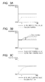
- FIG. 3A is a graph showing a relationship among an input control value, a final control value, and a lens position.
- FIG. 3B is a graph showing a relationship among the input control value, the final control value, and the lens position.
- FIG. 3C is a graph showing a relationship among the input control value, the final control value, and the lens position.
- FIG. 4 is a control diagram in calculating a matching position according to the first embodiment.
- FIG. 5A is a graph showing a relationship among the input control value, the final control value, and the lens position in matching according to the first embodiment.
- FIG. 5B is a graph showing a relationship among the input control value, the final control value, and the lens position in matching according to the first embodiment.
- FIG. 6 is a flowchart of a matching position calculating process according to the first embodiment.
- FIG. 7 is a flowchart of the matching position calculating process in the case of using a constant correction value.
- FIG. 8A is a graph showing a relationship among the input control value, the final control value, and the lens position in the case of using a correction value ⁇ .
- FIG. 8B is a graph showing a relationship among the input control value, the final control value, and the lens position in the case of using the correction value ⁇ .
- FIG. 9 schematically illustrates an operating apparatus.
- FIG. 10A is a graph showing a relationship between an input control value and a final control value in matching.
- FIG. 10B is a graph showing a relationship between the input control value and the final control value in matching.
- FIG. 1 is a block diagram illustrating a configuration according to an embodiment of the present invention.
- FIGS. 1 to 8B a lens apparatus according to a first embodiment of the present invention will be described.
- FIG. 1 is a functional block diagram of a photographing system according to this embodiment.
- reference numeral 100 denotes a lens operating apparatus
- reference numeral 200 denotes an operating apparatus.
- the lens apparatus 100 includes a focus lens 101 , a zoom lens 102 , an iris 103 , a computing unit L (second controller) 110 , a matching position calculator (matching position deriver, deriving unit) 111 , and a communicating unit L 112 .
- the focus lens 101 is a lens that changes an object distance.
- the zoom lens 102 is a lens that changes a focal length.
- the iris 103 is a stop unit that adjusts the amount of light.
- the focus lens 101 is connected to a focus driving unit 104 and a focus position detector 105 .
- the zoom lens 102 is connected to a zoom driving unit 106 and a zoom position detector 107 .
- the iris 103 is connected to an iris driving unit 108 and an iris position detector 109 .
- the focus position detector 105 In accordance with driving of the focus lens 101 , the focus position detector 105 outputs a position signal to the computing unit L 110 . Similarly, in accordance with driving of the zoom lens 102 , the zoom position detector 107 outputs a position signal to the computing unit L (second controller) 110 . In accordance with driving of the iris 103 , the iris position detector 109 outputs a position signal to the computing unit L (second controller) 110 .
- the computing unit L 110 outputs communication data to the communicating unit L 112 , and receives an instructed position from the communicating unit L 112 .
- the received instructed position (hereinafter referred to as an input control value, an input value) is subjected to various correction processes in accordance with conditions of the lens apparatus, thereby calculating (deriving) a control (hereinafter referred to as a final control value, a control value).
- a drive signal (hereinafter referred to as an output control value) is calculated (derived) by using a control parameter such as a gain with respect to the final control value, and the calculated output control value is output to the driving unit.
- the focus lens 101 is driven by outputting an output control value for focusing calculated (derived) using a focus instructed position and a correction value related to the focusing to the focus driving unit 104 .
- the zoom lens 102 is driven by outputting an output control value for zooming to the zoom driving unit 106 .
- the iris 103 is driven by outputting the output control value of the iris to the iris driving unit 108 .
- control correction processes in accordance with conditions of the lens apparatus described above will be described in detail later.
- a final control value and a correction value (hereinafter referred to as a control correction value) calculated (derived) in the control correction process are output to the matching position calculator 111 , and a matching position input from the matching position calculator 111 is output to the communicating unit L 112 .
- the matching position calculator 111 calculates (derives) a matching position, and outputs the calculated matching position to the computing unit L 110 .
- a method for calculating the matching position will be described in detail later.
- the communicating unit L 112 transmits communication data input from the computing unit L 110 to the operating apparatus 200 , and outputs the instructed position received from the operating apparatus 200 to the computing unit L 110 .
- the operating apparatus 200 mainly includes communicating unit D 201 , an operating unit (endless operating unit) 202 , a position detector D 203 , and a computing unit D (first controller) 204 .
- the communicating unit D 201 outputs communication data received from the lens apparatus 100 to the computing unit D 204 , and transmits an instructed position input from the computing unit D 204 to the lens apparatus 100 .
- the operating unit 202 is an operating member operated by a user.
- the operating unit 202 is a rotary operating member as illustrated in FIG. 9 , and is an endless operating apparatus.
- the position detector D 203 With rotational movement of the operating member, the position detector D 203 outputs a position signal to the computing unit D 204 .
- the computing unit D 204 calculates (derives) an instructed position, and outputs the calculated instructed position to the communicating unit D 201 . If the communication data input from the communicating unit D 201 is a matching position, the matching position is output to the communicating unit D 201 as the instructed position.
- the instructed position transmitted from the operating apparatus 200 to the lens apparatus 100 is a focus instructed position.
- the control correction value ⁇ in the integration process is a value obtained by integrating a difference between the lens position and the input control value with respect to time.
- the control correction value ⁇ is continuously added to the input control value. For example, in a case where the optical axis direction that is a moving direction of the lens is not horizontal, and the lens is subjected to a force in one moving direction under its own weight, the lens position can be moved closer to the input control value by performing the integration process.
- control correction process is performed by the computing unit L 110 , and a control correction process is performed by using the integration process.
- FIG. 2 is a control diagram in calculating (deriving) an output control value performed by the computing unit L 110 .
- FIGS. 3A, 3B, and 3C illustrate relationships among the input control value, the final control value, and the lens position.
- FIG. 3A shows a relationship between the input control value and the lens position in the case of performing no integration process.
- FIG. 3A demonstrates that the lens position is separated from the input control value. As described above, this relationship is established in the case where the lens apparatus is disposed in a tilted orientation so that the moving direction of the lens is not horizontal and the lens is subjected to a force in one moving direction under its own weight.
- FIG. 3B illustrates a relationship between the input control value and the final control value in the case of performing the integration process from time T 0 .
- the hatched portion in the graph indicates the control correction value ⁇ calculated (derived) from Equation (6).
- the value calculated (derived) from Equation (7) is the final control value.
- a value obtained by multiplying the final control value by a control parameter such as a gain is output as an output control value to the driving unit.
- FIG. 3C illustrates a relationship between the input control value and the lens position in the case of performing the integration process. As compared to FIG. 3A , the lens position can be moved closer to the input control value by performing the integration process.
- the computing unit L 110 calculates a control correction value ⁇ through the integration process. Thereafter, the input control value and the control correction value ⁇ are substituted into Equation. (7), thereby calculating a final control value for focusing.
- the final control value for focusing obtained from Equation (7), a focus control gain value ⁇ , and a focus lens position are substituted into Equation (8), thereby calculating an output control value for focusing.
- FIG. 4 is a control diagram in deriving a matching position in the case of performing the integration process.
- control correction value ⁇ is 0 (zero).
- FIGS. 5A and 5B show relationships among the input control value, the final control value, and the lens position in the case of performing matching at time T. Hatched portions in the graphs indicate the control correction value ⁇ .
- the lens apparatus includes a preset operation of controlling the position to a previously stored position with an operation instruction from a switch or another device. For example, description will be given on a case where the operation right is switched from a focus position control by the preset operation to the operating apparatus 200 at time T.
- the final control value in this preset operation is Ctl_FIN_org.
- FIG. 5A shows a relationship between the input control value and the final control value.
- FIG. 5B illustrates a relationship between the input control value and the lens position.
- the final control value after matching becomes Ctl_FIN_org, and the final control value does not change before and after executing matching, and the lens position does not change, either, as shown in the graph.
- the final control value is the matching position
- unintentional driving of the lens occurs in switching the operation right.
- this problem can be solved by using the value obtained from Equation (9) as the matching position.
- FIG. 6 is a flowchart showing a matching position deriving process in this embodiment.
- the final control value Ctl_FIN is input from the computing unit L 110 to the matching position calculator 111 and is set as a matching position P, and then, the process proceeds to S 602 .
- S 603 it is determined whether the control correction process is performed or not. If the control correction process is performed, the process proceeds to S 605 , and otherwise, the process proceeds to S 604 .
- the matching position calculator 111 calculates (derives) a matching position P by subtracting the final control value Ctl_FIN input from the computing unit L 110 and the control correction value ⁇ into Equation (9), and the process is finished.
- the matching position can be corrected by computation in accordance with conditions of the lens, thereby providing a lens apparatus that can prevent unintentional lens driving in switching the operation right.
- the instructed position from the operating apparatus is used as the focus instructed position.
- the present invention is not limited to this example, and the instructed position from the operating apparatus may be a zoom instructed position or an iris instructed position.
- the driving target of the lens is a focus lens in the above embodiment.
- the present invention is not limited to this example, and the driving target may be a zoom lens or an iris.
- control correction process is the integration process.
- the present invention is not limited to this example, and the control correction process only needs to be a process of calculating a final control value by performing the correction process on the input control value inside the lens.
- the matching position can be calculated by substituting the control correction value used in the control correction process into Equation (9).
- the lens apparatus 100 may have an iris correcting function including an extender that can be inserted and removed in/from an optical path, changes a focal length, and is not illustrated in FIG. 1 and configured to correct an iris (aperture stop) so that the iris (aperture stop) is automatically driven toward an open end by inserting the extender into the optical path.
- the lens apparatus 100 includes an unillustrated nonvolatile memory that stores a correction value ⁇ of the iris correcting function in accordance with a magnification of the extender.
- the instructed position transmitted from the operating apparatus 200 to the lens apparatus 100 is an iris instructed position.
- FIG. 7 is a flowchart showing a matching position calculating process in calculating a matching position from Equation (10).
- steps S 601 to S 605 shown in FIG. 6 are the same, and S 701 , which is a subtraction process of a correction value ⁇ described with reference to Equation (10), is added immediately before the process of the flowchart shown in FIG. 6 is finished.
- FIGS. 8A and 8B show relationships among the input control value, the final control value, and the lens position in the case of performing matching at time T in calculating a matching position from Equation (10). Hatched portions in the graphs indicate the control correction value ⁇ and double hatched portions in the graphs indicate the correction value ⁇ .
- the final control value in the preset operation is set at Ctl_FIN_org in view of the case where the operation right is switched to the operating apparatus 200 at time T from iris position control by the preset operation.
- FIG. 8A illustrates a relationship between the input control value and the final control value.
- FIG. 8B illustrates a relationship between the input control value and the lens position.
- the final control value after matching is Ctl_FIN_org, and the final control value does not change before and after the execution of the matching.
- the lens position does not change, either.
- the constant correction value ⁇ has been described using the iris correction value.
- the present invention is not limited to this example, and the correction process only needs to be performed on the input control value.
- the constant correction value ⁇ may be read out from a nonvolatile memory as described above, or may be a predetermined value or a value that dynamically changes in accordance with conditions of the lens.
- problems described above can be solved by using, as a matching position, a value obtained by subtracting a correction value used in the correction process into Equation (10) from the final control value.
- the matching position can be corrected by computation in accordance with conditions of the lens, thereby providing a lens apparatus that can prevent unintentional lens driving in switching an operation right.
- an image pickup element that receives object light from the lens apparatus can provide an image pickup apparatus that can prevent unintentional lens driving in switching an operation right of an endless operating unit.
- Embodiment(s) of the present invention can also be realized by a computer of a system or apparatus that reads out and executes computer executable instructions (e.g., one or more programs) recorded on a storage medium (which may also be referred to more fully as a ‘non-transitory computer-readable storage medium’) to perform the functions of one or more of the above-described embodiment(s) and/or that includes one or more circuits (e.g., application specific integrated circuit (ASIC)) for performing the functions of one or more of the above-described embodiment(s), and by a method performed by the computer of the system or apparatus by, for example, reading out and executing the computer executable instructions from the storage medium to perform the functions of one or more the above-described embodiment (s) and/or controlling the one or more circuits to perform the functions of one or more of the above-described embodiment(s).
- computer executable instructions e.g., one or more programs
- a storage medium which may also be referred to more fully as a ‘
- the computer may comprise one or more processors (e.g., central processing unit (CPU), micro processing unit (MPU)) and may include a network of separate computers or separate processors to read out and execute the computer executable instructions.
- the computer executable instructions may be provided to the computer, for example, from a network or the storage medium.
- the storage medium may include, for example, one or more of a hard disk, a random-access memory (RAM), a read only memory (ROM), a storage of distributed computing systems, an optical disk (such as a compact disc (CD), digital versatile disc (DVD), or Blu-ray Disc (BD)TM), a flash memory device, a memory card, and the like.
Landscapes
- Physics & Mathematics (AREA)
- General Physics & Mathematics (AREA)
- Optics & Photonics (AREA)
- Engineering & Computer Science (AREA)
- Multimedia (AREA)
- Signal Processing (AREA)
- Lens Barrels (AREA)
- Studio Devices (AREA)
- Diaphragms For Cameras (AREA)
- Structure And Mechanism Of Cameras (AREA)
Abstract
Description
difference value=final control value (before switching)−input control value (1)
final control value (after switching)=input control value+difference value (2)
final control value (before switching)=input control value (before switching)+correction value α (3)
difference value=final control value (before switching)−correction value α−input control value (4)
final control value (after switching)=final control value (before switching)−correction value α (5)
control correction value α=∫(lens position—input control value)dt (6)
final control value (Ctl_FIN)=(input control value (Ctl_IN)+control correction value (α)) (7)
output control value (Ctl_OUT)=(final control value (Ctl_FIN)=lens position (Fol))×control parameter (β) (8)
matching position (P)=final control value (Ctl_FIN)−control correction value (α) (9)
matching position (P)=final control value (Ctl_FIN)−control correction value (α)−correction value (γ) (10)
Claims (9)
Applications Claiming Priority (2)
| Application Number | Priority Date | Filing Date | Title |
|---|---|---|---|
| JP2014257618A JP6506548B2 (en) | 2014-12-19 | 2014-12-19 | Lens device and imaging device having the same |
| JP2014-257618 | 2014-12-19 |
Publications (2)
| Publication Number | Publication Date |
|---|---|
| US20160182810A1 US20160182810A1 (en) | 2016-06-23 |
| US9591197B2 true US9591197B2 (en) | 2017-03-07 |
Family
ID=56130993
Family Applications (1)
| Application Number | Title | Priority Date | Filing Date |
|---|---|---|---|
| US14/962,090 Expired - Fee Related US9591197B2 (en) | 2014-12-19 | 2015-12-08 | Lens apparatus and image pickup apparatus including the same |
Country Status (2)
| Country | Link |
|---|---|
| US (1) | US9591197B2 (en) |
| JP (1) | JP6506548B2 (en) |
Families Citing this family (1)
| Publication number | Priority date | Publication date | Assignee | Title |
|---|---|---|---|---|
| JP7608205B2 (en) * | 2021-02-26 | 2025-01-06 | キヤノン株式会社 | Operation device, optical device, and imaging device |
Citations (3)
| Publication number | Priority date | Publication date | Assignee | Title |
|---|---|---|---|---|
| JP3777502B2 (en) | 2001-11-13 | 2006-05-24 | フジノン株式会社 | Lens device and lens operation unit |
| US20110158627A1 (en) * | 2009-12-28 | 2011-06-30 | Canon Kabushiki Kaisha | Image pickup apparatus including focus operating apparatus and focus control method |
| US20110243540A1 (en) * | 2010-03-31 | 2011-10-06 | Canon Kabushiki Kaisha | Focus adjusting apparatus |
Family Cites Families (4)
| Publication number | Priority date | Publication date | Assignee | Title |
|---|---|---|---|---|
| JPH0651176A (en) * | 1992-07-28 | 1994-02-25 | Nikon Corp | Lens barrel |
| JP2000162692A (en) * | 1998-11-27 | 2000-06-16 | Fuji Photo Optical Co Ltd | Extender-mounted lens device |
| DE202009014504U1 (en) * | 2009-10-27 | 2010-02-04 | Longmore, Martin | Control device for a lens of a camera |
| JP5546272B2 (en) * | 2010-02-05 | 2014-07-09 | キヤノン株式会社 | Optical device and control method thereof |
-
2014
- 2014-12-19 JP JP2014257618A patent/JP6506548B2/en not_active Expired - Fee Related
-
2015
- 2015-12-08 US US14/962,090 patent/US9591197B2/en not_active Expired - Fee Related
Patent Citations (3)
| Publication number | Priority date | Publication date | Assignee | Title |
|---|---|---|---|---|
| JP3777502B2 (en) | 2001-11-13 | 2006-05-24 | フジノン株式会社 | Lens device and lens operation unit |
| US20110158627A1 (en) * | 2009-12-28 | 2011-06-30 | Canon Kabushiki Kaisha | Image pickup apparatus including focus operating apparatus and focus control method |
| US20110243540A1 (en) * | 2010-03-31 | 2011-10-06 | Canon Kabushiki Kaisha | Focus adjusting apparatus |
Also Published As
| Publication number | Publication date |
|---|---|
| US20160182810A1 (en) | 2016-06-23 |
| JP6506548B2 (en) | 2019-04-24 |
| JP2016118627A (en) | 2016-06-30 |
Similar Documents
| Publication | Publication Date | Title |
|---|---|---|
| US10244170B2 (en) | Image-shake correction apparatus and control method thereof | |
| US9723209B2 (en) | Image shake correction device, image pickup apparatus, and control method | |
| EP3462235B1 (en) | Control apparatus, image capturing apparatus, control method, program, and storage medium | |
| EP3477355A1 (en) | Lens control apparatus, imaging apparatus including lens control apparatus, and lens control method | |
| US10091424B2 (en) | Image blur correction apparatus, method for controlling the same, and storage medium | |
| US10425571B2 (en) | Focusing and image pickup apparatus, storage medium, and method for controlling positioning of a focus lens | |
| US9918004B2 (en) | Camera body capable of driving an image sensor along an optical axis in response to a change in an optical state of an object image | |
| US9432567B2 (en) | Image pickup apparatus and imaging method that perform focus action following zoom action | |
| JP6995561B2 (en) | Image stabilization device and its control method, image pickup device | |
| US20160301858A1 (en) | Control apparatus, storage medium for storing control program, control method, and optical apparatus | |
| US10165188B2 (en) | Optical apparatus, display controlling method, and non-transitory computer readable storage medium storing a program, that display object distance information | |
| EP3015891B1 (en) | Focus adjustment device, camera system, and focus adjustment method | |
| US9591197B2 (en) | Lens apparatus and image pickup apparatus including the same | |
| US11445115B2 (en) | Image capturing and stabilization apparatus and method capable of performing image stabilization control by moving an image sensor | |
| US20250056120A1 (en) | Control apparatus, image pickup apparatus, lens apparatus, control method, and storage medium, that determine correction ratios between multiple image stabilizers | |
| JP6674254B2 (en) | Lens device and imaging device having the same | |
| US12309494B2 (en) | Image blur correction control apparatus and control method | |
| US10887503B2 (en) | Control apparatus, image capturing apparatus, and control method | |
| JP6425440B2 (en) | Imaging apparatus and imaging method | |
| US11997387B2 (en) | Image blur correction apparatus, control method thereof, and storage medium | |
| US11381728B2 (en) | Image capture apparatus and method for controlling the same | |
| US12126908B2 (en) | Image capturing apparatus obtaining a plurality of images to be used for generation of a combined image and method for controlling the same, and non-transitory computer-readable storage medium | |
| US20150077621A1 (en) | Image pickup apparatus, image pickup system, method of controlling image pickup apparatus, and non-transitory computer-readable storage medium | |
| JP6674253B2 (en) | Lens device and imaging device |
Legal Events
| Date | Code | Title | Description |
|---|---|---|---|
| AS | Assignment |
Owner name: CANON KABUSHIKI KAISHA, JAPAN Free format text: ASSIGNMENT OF ASSIGNORS INTEREST;ASSIGNOR:SUZUKI, JUNICHI;REEL/FRAME:037900/0936 Effective date: 20151119 |
|
| STCF | Information on status: patent grant |
Free format text: PATENTED CASE |
|
| MAFP | Maintenance fee payment |
Free format text: PAYMENT OF MAINTENANCE FEE, 4TH YEAR, LARGE ENTITY (ORIGINAL EVENT CODE: M1551); ENTITY STATUS OF PATENT OWNER: LARGE ENTITY Year of fee payment: 4 |
|
| FEPP | Fee payment procedure |
Free format text: MAINTENANCE FEE REMINDER MAILED (ORIGINAL EVENT CODE: REM.); ENTITY STATUS OF PATENT OWNER: LARGE ENTITY |
|
| LAPS | Lapse for failure to pay maintenance fees |
Free format text: PATENT EXPIRED FOR FAILURE TO PAY MAINTENANCE FEES (ORIGINAL EVENT CODE: EXP.); ENTITY STATUS OF PATENT OWNER: LARGE ENTITY |
|
| STCH | Information on status: patent discontinuation |
Free format text: PATENT EXPIRED DUE TO NONPAYMENT OF MAINTENANCE FEES UNDER 37 CFR 1.362 |
|
| FP | Lapsed due to failure to pay maintenance fee |
Effective date: 20250307 |