US9586602B2 - Brake unit for a vehicle and vehicle having such a brake unit - Google Patents
Brake unit for a vehicle and vehicle having such a brake unit Download PDFInfo
- Publication number
- US9586602B2 US9586602B2 US14/765,065 US201414765065A US9586602B2 US 9586602 B2 US9586602 B2 US 9586602B2 US 201414765065 A US201414765065 A US 201414765065A US 9586602 B2 US9586602 B2 US 9586602B2
- Authority
- US
- United States
- Prior art keywords
- brake
- brake unit
- locking
- locking element
- force
- Prior art date
- Legal status (The legal status is an assumption and is not a legal conclusion. Google has not performed a legal analysis and makes no representation as to the accuracy of the status listed.)
- Expired - Fee Related, expires
Links
Images


Classifications
-
- B—PERFORMING OPERATIONS; TRANSPORTING
- B61—RAILWAYS
- B61H—BRAKES OR OTHER RETARDING DEVICES SPECIALLY ADAPTED FOR RAIL VEHICLES; ARRANGEMENT OR DISPOSITION THEREOF IN RAIL VEHICLES
- B61H15/00—Wear-compensating mechanisms, e.g. slack adjusters
- B61H15/0007—Wear-compensating mechanisms, e.g. slack adjusters mechanical and self-acting in one direction
- B61H15/0014—Wear-compensating mechanisms, e.g. slack adjusters mechanical and self-acting in one direction by means of linear adjustment
- B61H15/0028—Wear-compensating mechanisms, e.g. slack adjusters mechanical and self-acting in one direction by means of linear adjustment with screw-thread and nut
-
- B—PERFORMING OPERATIONS; TRANSPORTING
- B60—VEHICLES IN GENERAL
- B60T—VEHICLE BRAKE CONTROL SYSTEMS OR PARTS THEREOF; BRAKE CONTROL SYSTEMS OR PARTS THEREOF, IN GENERAL; ARRANGEMENT OF BRAKING ELEMENTS ON VEHICLES IN GENERAL; PORTABLE DEVICES FOR PREVENTING UNWANTED MOVEMENT OF VEHICLES; VEHICLE MODIFICATIONS TO FACILITATE COOLING OF BRAKES
- B60T13/00—Transmitting braking action from initiating means to ultimate brake actuator with power assistance or drive; Brake systems incorporating such transmitting means, e.g. air-pressure brake systems
- B60T13/10—Transmitting braking action from initiating means to ultimate brake actuator with power assistance or drive; Brake systems incorporating such transmitting means, e.g. air-pressure brake systems with fluid assistance, drive, or release
- B60T13/58—Combined or convertible systems
- B60T13/588—Combined or convertible systems both fluid and mechanical assistance or drive
-
- B—PERFORMING OPERATIONS; TRANSPORTING
- B60—VEHICLES IN GENERAL
- B60T—VEHICLE BRAKE CONTROL SYSTEMS OR PARTS THEREOF; BRAKE CONTROL SYSTEMS OR PARTS THEREOF, IN GENERAL; ARRANGEMENT OF BRAKING ELEMENTS ON VEHICLES IN GENERAL; PORTABLE DEVICES FOR PREVENTING UNWANTED MOVEMENT OF VEHICLES; VEHICLE MODIFICATIONS TO FACILITATE COOLING OF BRAKES
- B60T13/00—Transmitting braking action from initiating means to ultimate brake actuator with power assistance or drive; Brake systems incorporating such transmitting means, e.g. air-pressure brake systems
- B60T13/10—Transmitting braking action from initiating means to ultimate brake actuator with power assistance or drive; Brake systems incorporating such transmitting means, e.g. air-pressure brake systems with fluid assistance, drive, or release
- B60T13/66—Electrical control in fluid-pressure brake systems
- B60T13/665—Electrical control in fluid-pressure brake systems the systems being specially adapted for transferring two or more command signals, e.g. railway systems
-
- B—PERFORMING OPERATIONS; TRANSPORTING
- B60—VEHICLES IN GENERAL
- B60T—VEHICLE BRAKE CONTROL SYSTEMS OR PARTS THEREOF; BRAKE CONTROL SYSTEMS OR PARTS THEREOF, IN GENERAL; ARRANGEMENT OF BRAKING ELEMENTS ON VEHICLES IN GENERAL; PORTABLE DEVICES FOR PREVENTING UNWANTED MOVEMENT OF VEHICLES; VEHICLE MODIFICATIONS TO FACILITATE COOLING OF BRAKES
- B60T17/00—Component parts, details, or accessories of power brake systems not covered by groups B60T8/00, B60T13/00 or B60T15/00, or presenting other characteristic features
- B60T17/08—Brake cylinders other than ultimate actuators
- B60T17/16—Locking of brake cylinders
-
- B—PERFORMING OPERATIONS; TRANSPORTING
- B60—VEHICLES IN GENERAL
- B60T—VEHICLE BRAKE CONTROL SYSTEMS OR PARTS THEREOF; BRAKE CONTROL SYSTEMS OR PARTS THEREOF, IN GENERAL; ARRANGEMENT OF BRAKING ELEMENTS ON VEHICLES IN GENERAL; PORTABLE DEVICES FOR PREVENTING UNWANTED MOVEMENT OF VEHICLES; VEHICLE MODIFICATIONS TO FACILITATE COOLING OF BRAKES
- B60T17/00—Component parts, details, or accessories of power brake systems not covered by groups B60T8/00, B60T13/00 or B60T15/00, or presenting other characteristic features
- B60T17/18—Safety devices; Monitoring
- B60T17/22—Devices for monitoring or checking brake systems; Signal devices
- B60T17/228—Devices for monitoring or checking brake systems; Signal devices for railway vehicles
-
- B—PERFORMING OPERATIONS; TRANSPORTING
- B61—RAILWAYS
- B61H—BRAKES OR OTHER RETARDING DEVICES SPECIALLY ADAPTED FOR RAIL VEHICLES; ARRANGEMENT OR DISPOSITION THEREOF IN RAIL VEHICLES
- B61H5/00—Applications or arrangements of brakes with substantially radial braking surfaces pressed together in axial direction, e.g. disc brakes
-
- F—MECHANICAL ENGINEERING; LIGHTING; HEATING; WEAPONS; BLASTING
- F16—ENGINEERING ELEMENTS AND UNITS; GENERAL MEASURES FOR PRODUCING AND MAINTAINING EFFECTIVE FUNCTIONING OF MACHINES OR INSTALLATIONS; THERMAL INSULATION IN GENERAL
- F16D—COUPLINGS FOR TRANSMITTING ROTATION; CLUTCHES; BRAKES
- F16D55/00—Brakes with substantially-radial braking surfaces pressed together in axial direction, e.g. disc brakes
- F16D55/02—Brakes with substantially-radial braking surfaces pressed together in axial direction, e.g. disc brakes with axially-movable discs or pads pressed against axially-located rotating members
- F16D55/22—Brakes with substantially-radial braking surfaces pressed together in axial direction, e.g. disc brakes with axially-movable discs or pads pressed against axially-located rotating members by clamping an axially-located rotating disc between movable braking members, e.g. movable brake discs or brake pads
- F16D55/224—Brakes with substantially-radial braking surfaces pressed together in axial direction, e.g. disc brakes with axially-movable discs or pads pressed against axially-located rotating members by clamping an axially-located rotating disc between movable braking members, e.g. movable brake discs or brake pads with a common actuating member for the braking members
- F16D55/2245—Brakes with substantially-radial braking surfaces pressed together in axial direction, e.g. disc brakes with axially-movable discs or pads pressed against axially-located rotating members by clamping an axially-located rotating disc between movable braking members, e.g. movable brake discs or brake pads with a common actuating member for the braking members in which the common actuating member acts on two levers carrying the braking members, e.g. tong-type brakes
-
- F—MECHANICAL ENGINEERING; LIGHTING; HEATING; WEAPONS; BLASTING
- F16—ENGINEERING ELEMENTS AND UNITS; GENERAL MEASURES FOR PRODUCING AND MAINTAINING EFFECTIVE FUNCTIONING OF MACHINES OR INSTALLATIONS; THERMAL INSULATION IN GENERAL
- F16D—COUPLINGS FOR TRANSMITTING ROTATION; CLUTCHES; BRAKES
- F16D65/00—Parts or details
- F16D65/14—Actuating mechanisms for brakes; Means for initiating operation at a predetermined position
- F16D65/16—Actuating mechanisms for brakes; Means for initiating operation at a predetermined position arranged in or on the brake
- F16D65/18—Actuating mechanisms for brakes; Means for initiating operation at a predetermined position arranged in or on the brake adapted for drawing members together, e.g. for disc brakes
-
- F—MECHANICAL ENGINEERING; LIGHTING; HEATING; WEAPONS; BLASTING
- F16—ENGINEERING ELEMENTS AND UNITS; GENERAL MEASURES FOR PRODUCING AND MAINTAINING EFFECTIVE FUNCTIONING OF MACHINES OR INSTALLATIONS; THERMAL INSULATION IN GENERAL
- F16D—COUPLINGS FOR TRANSMITTING ROTATION; CLUTCHES; BRAKES
- F16D65/00—Parts or details
- F16D65/38—Slack adjusters
- F16D65/40—Slack adjusters mechanical
- F16D65/52—Slack adjusters mechanical self-acting in one direction for adjusting excessive play
- F16D65/56—Slack adjusters mechanical self-acting in one direction for adjusting excessive play with screw-thread and nut
-
- F—MECHANICAL ENGINEERING; LIGHTING; HEATING; WEAPONS; BLASTING
- F16—ENGINEERING ELEMENTS AND UNITS; GENERAL MEASURES FOR PRODUCING AND MAINTAINING EFFECTIVE FUNCTIONING OF MACHINES OR INSTALLATIONS; THERMAL INSULATION IN GENERAL
- F16D—COUPLINGS FOR TRANSMITTING ROTATION; CLUTCHES; BRAKES
- F16D2121/00—Type of actuator operation force
- F16D2121/02—Fluid pressure
- F16D2121/04—Fluid pressure acting on a piston-type actuator, e.g. for liquid pressure
-
- F—MECHANICAL ENGINEERING; LIGHTING; HEATING; WEAPONS; BLASTING
- F16—ENGINEERING ELEMENTS AND UNITS; GENERAL MEASURES FOR PRODUCING AND MAINTAINING EFFECTIVE FUNCTIONING OF MACHINES OR INSTALLATIONS; THERMAL INSULATION IN GENERAL
- F16D—COUPLINGS FOR TRANSMITTING ROTATION; CLUTCHES; BRAKES
- F16D2121/00—Type of actuator operation force
- F16D2121/14—Mechanical
-
- F—MECHANICAL ENGINEERING; LIGHTING; HEATING; WEAPONS; BLASTING
- F16—ENGINEERING ELEMENTS AND UNITS; GENERAL MEASURES FOR PRODUCING AND MAINTAINING EFFECTIVE FUNCTIONING OF MACHINES OR INSTALLATIONS; THERMAL INSULATION IN GENERAL
- F16D—COUPLINGS FOR TRANSMITTING ROTATION; CLUTCHES; BRAKES
- F16D2125/00—Components of actuators
- F16D2125/18—Mechanical mechanisms
- F16D2125/20—Mechanical mechanisms converting rotation to linear movement or vice versa
- F16D2125/34—Mechanical mechanisms converting rotation to linear movement or vice versa acting in the direction of the axis of rotation
- F16D2125/40—Screw-and-nut
Definitions
- the invention relates to a brake unit for a vehicle, in particular a rail vehicle, having a brake cylinder, a brake piston which is axially guided in the brake cylinder, and means for adjusting a clearance, said means comprising two first stops that are assigned to each other and come to rest against each other when the brake unit is opened, wherein one of the first stops is formed on a locking element which is actively connected to the brake piston.
- Such a brake unit is disclosed in the publication U.S. Pat. No. 4,319,671 A, for example, in which a piston is used as a locking element, said piston being actively connected to the brake piston via the hydraulic fluid and coming to rest against an edge of a casing section of the brake cylinder when the brake unit is opened.
- the object of the invention is to allow such an opening of the brake unit in a simple and time-saving manner.
- a brake unit for a vehicle in particular a rail vehicle, having a brake cylinder, a brake piston which is axially guided in the brake cylinder, and means for adjusting a clearance with two first stops that are assigned to each other and come to rest against each other when the brake unit is opened, and wherein one of the first stops is formed on a locking element that is actively connected to the brake piston
- a locking member is engaged with the locking element under the force of a preloaded spring in such a manner that the locking element is blocked by the locking member when the first stops come to rest against each other, and that actuation means are suitably formed to displace the locking member that is engaged with the locking element, against the force of the preloaded spring, into a position released from the locking element.
- the brake piston can be displaced far beyond the clearance, thereby rendering the inventive brake unit particularly easy to maintain.
- the simple structure of the brake unit result in a reduction in weight and costs.
- the actuation means are preferably mechanical, such that the brake unit can be opened manually without difficulty for the purpose of maintenance tasks.
- the locking element can be a locking slide which overlaps a carrier that is formed on the brake piston, and the locking member can be a locking pawl which engages into teeth of the locking slide under the force of the preloaded spring.
- the locking element can be a locking wheel and the locking member can be a threaded spindle which is coupled to the brake piston via a screw-thread drive and is supported at the brake cylinder via a bearing.
- the threaded spindle is preferably a threaded spindle which is concentrically screwed into the brake piston and is not self-locking.
- the actuation means in this case preferably comprise a tie rod, a tie rod screw, and a pin which can be axially displaced by rotating the tie rod screw via a guide in the tie rod, wherein the preloaded spring is supported at the tie rod and wherein the threaded spindle comprises actuation surfaces which project into the path of movement of the pin, said actuation surfaces being so formed that the threaded spindle is displaced into the position released from the locking element when the pin is displaced against the force of the preloaded spring.
- the tie rod screw may be coupled to a tool via an interface, said tool allowing the tie rod screw to be turned from an easily accessible position. It is also advantageous here that the mechanical components which are involved in the adjustment of the clearance and in returning the brake piston for the purpose of fully opening the brake unit are situated in the hydraulic region, thereby significantly reducing the risk of jamming or wear to these components.
- connection between locking element and locking member may also be embodied as a frictional connection instead of the toothed engagement.
- an arresting pawl prefferably formed to block the locking element when the brake unit is in a closed position.
- the brake unit functions as a parking brake (restraining brake) when the locking element is blocked thus.
- the means for adjusting the clearance comprises two second stops that are assigned to each other and come to rest against each other when the brake unit is closed, wherein one of the second stops is formed on the locking element into which the locking member, under the force of the preloaded spring, engages in such a way that the locking element can continue to catch or slip relative to the locking member under the force of the brake piston when the second stops come to rest against each other, and therefore the clearance is automatically readjusted when the frictional partners wear.
- the invention also relates to a vehicle, in particular a rail vehicle, having a chassis to which a brake unit according to the invention is attached for the purpose of frictional engagement using braking means of a wheelset of the chassis.
- FIG. 1 shows a vehicle according to the invention in the form of a rail vehicle, wherein wheel sets of bogies are each assigned at least one brake unit according to the invention
- FIG. 2 shows a first embodiment variant of the brake unit according to the invention
- FIGS. 3 and 4 show a second embodiment variant of the brake unit according to the invention
- FIGS. 5 and 6 show various sectional views of a brake piston entity of the brake unit as per FIGS. 3 and 4 .
- FIGS. 7 to 12 show parts of the brake piston entity as per FIGS. 5 and 6 in various positions of its motion sequence.
- the rail vehicle 1 has cars 2 . 1 , 2 . 2 , . . . , 2 . n whose car bodies are each supported via a secondary suspension system by two chassis in the form of bogies 3 in a manner which is not shown here.
- the bogies 3 have two wheel sets 4 in each case.
- Each of the wheel sets 4 has a shaft 5 and wheels 6 which are held at the ends thereof.
- the shafts 5 of the wheel sets 4 are rotatably mounted in wheel set bearings in a manner which is not shown, said wheel set bearings being linked via a casing and a primary suspension system to a bogie frame 7 of the respective bogie 3 .
- the rail vehicle 1 further comprises a brake system which is designated 8 as a whole.
- Each shaft 5 of the rail vehicle 1 is normally assigned at least one inventive brake unit 9 in each case. Therefore each of the cars 2 . 1 , 2 . 2 , . . . , 2 . n has at least four of these brake units 9 .
- Each of the brake units 9 has a brake actuator 10 and first brake means 11 , which are actuated by the brake actuator 10 and take the form of a brake application entity 13 that is equipped with brake pads 12 .
- the first brake means 11 of each of these brake units 9 interacts in each case with second brake means 14 in the form of a brake disc 16 that is equipped with braking surfaces 15 .
- the braking surfaces 15 here take the form of two brake disc sections 16 . 1 , 16 . 2 , which are attached to the two sides of a wheel 6 that is assigned to the brake unit 9 , such that the wheel 6 having the two brake disc sections 16 . 1 , 16 . 2 represents the brake disc 16 in the form of a wheel brake disc (see FIGS. 2 and 3 ).
- the wheel brake disc instead of the wheel brake disc, however, it is also possible to provide an axle-mounted brake disc, in which case a separate disc having braking surfaces is arranged in a non-rotatable manner on the shaft 5 in addition to the wheel.
- the first brake means can also interact with a second brake means in the form of the wheel or in the form of a brake drum.
- the brake application entity 13 which is equipped with the brake pads 12 can be applied across the brake disc 16 for the purpose of producing a frictional engagement between the first brake means 11 and the second brake means 14 .
- the brake actuator 10 is an electro-hydraulic brake actuator.
- the brake system 8 has a central control device 17 a and, in each of the cars 2 . 1 , 2 . 2 , . . . , 2 . n , a brake controller 17 b in the form of one or two brake control devices 17 b. 1 and 17 b. 2 .
- the brake control devices 17 b. 1 and 17 b. 2 can be activated from the central control device 17 a of the brake system 8 via a wire train bus 18 a , said central control device 17 a being provided as part of a central vehicle control system, for example.
- the brake actuators 10 of the brake units 9 receive one brake instruction in each case via the brake controller 17 b .
- the brake instructions may be transferred to the brake actuators 10 via one or more control lines 18 b and/or a BUS and/or via radio in this case.
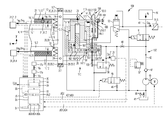
- FIG. 2 schematically shows a first embodiment variant 109 of the inventive brake unit with a first embodiment variant 110 of the brake actuator.
- FIGS. 3 and 4 show a second embodiment variant 209 of the inventive brake unit with a second embodiment variant 210 of the brake actuator, and FIGS. 5 to 12 show details of this second embodiment variant 210 of the brake actuator.
- the two embodiment variants 109 and 209 of the brake unit essentially differ only in the structural configuration of a brake piston entity, respectively designated 119 and 219 as a whole, of their respective brake actuators 110 and 210 , and therefore the components of the two embodiment variants 109 and 209 of the brake unit, said variants being developed in an essentially identical manner, are each designated by the same reference signs in the FIGS. 2 and 3 to 12 .
- both embodiment variants 109 and 209 of the brake unit 9 have a connecting part, designated 20 as a whole, on which the brake application entity 13 is held.
- the connecting part 20 comprises a brake bridge 20 . 1 and is permanently fixed to the bogie frame 7 by means of bolted connections 20 . 2 .
- the brake units 109 ; 209 may also be attached to the chassis at a different position, e.g. to a transmission casing or a wheelset flange of the bogie.
- the brake application entity 13 is formed as a brake caliper by means of two brake levers 21 .
- the brake application entity could however also be formed as a brake saddle.
- the position of the brake unit 109 ; 209 on the bogie frame 7 can be adjusted by means of the bolted connections 20 . 2 during the initial installation of the brake unit 109 ; 209 on the bogie frame 7 , but subsequent adjustment is very resource-intensive.
- each spring element 22 is assigned to each of the two brake levers 21 .
- a first end of each spring element 22 is supported at the respective brake lever 21 , and a second end is supported at the brake bridge 20 . 1 of the connecting part 20 .
- the prestressing force of each of the two spring elements 22 is adjustable. However, this is only shown for the second embodiment variant 209 of the brake unit here. According to FIGS. 3 and 4 , the adjustment of the prestressing force of each of the spring elements 22 is effected in each case by means of an adjustment entity that is designated 23 as a whole.
- the adjustment entities 23 comprise in each case an adjustment screw 23 . 1 (also referred to as an “adjusting screw” or “stop screw”), a threaded hole in the assigned brake lever 20 for engagement with the adjustment screw 23 . 1 , and a guide slot which is formed in the respective brake lever for guiding that end of the spring element which is supported at the brake lever, said end taking the form of a lever-type limb.
- an adjustment screw 23 . 1 also referred to as an “adjusting screw” or “stop screw”
- stop screw a threaded hole in the assigned brake lever 20 for engagement with the adjustment screw 23 . 1
- a guide slot which is formed in the respective brake lever for guiding that end of the spring element which is supported at the brake lever, said end taking the form of a lever-type limb.
- the adjustment of the prestressing forces of the spring elements 22 provides the means whereby a unilateral abutment of the brake means 11 , 14 can be dealt with quickly and easily during operational use. It is therefore possible e.g. to compensate for a relative offset of the attachment of the brake unit 109 ; 209 in a transverse direction y relative to the braking surfaces 15 of the brake disc 16 , and hence to centralize the brake unit 109 ; 209 relative to the brake disc 16 .
- the two brake levers 21 are pivotably connected to the connecting part 20 by means of connecting bolts 24 in each case, thus forming the brake caliper.
- First lever arms of the brake levers 21 are pivotably connected to supports 25 , 26 of the brake actuator 110 ; 210 .
- a reciprocating motion of the support 25 pushes the supports 25 , 26 away from each other, thereby spreading the first lever arms apart.
- the brake pads 12 are arranged at second lever arms of the brake levers 21 , and are applied across the brake disk 16 when the first lever arms are spread apart.
- the spring elements 22 In addition to the function of equalizing the clearance L of the brake pads 12 on both sides of the brake disc 16 (centering function), the spring elements 22 also perform a return function.
- the return function consists in opening the brake caliper when the brake actuator 110 ; 210 does not introduce any actuation force into the brake application entity for the purpose of applying the brake application entity 13 .
- the second embodiment variant 209 of the inventive brake unit is also equipped with an entity, designated 27 as a whole, which is provided to ensure the parallel movement of the brake pads but is not described in further detail here.
- the two embodiment variants 110 and 210 of the brake actuator comprise in each case a local electronics module 30 , a sensor entity 31 and an electro-hydraulic set point value force conversion entity 132 ; 232 , wherein the brake actuator 110 ; 210 with its components 30 , 31 and 132 ; 232 and the first brake means 11 are connected by means of the connecting part 20 to form an assembly.
- the local electronics module 30 comprises a set point value capture unit 33 , which is equipped with a set point value correction entity 34 .
- the local electronics module also comprises a set point value regulating entity 35 , a monitoring entity 36 , a fallback entity 37 and a switching entity 38 .
- the set point value capture unit 33 requests a brake set point value from at least one of the brake control devices 17 a. 1 or 17 b. 2 of the brake controller 17 b .
- the set point value correction entity 34 performs a wheel slide protection correction of the brake set point value as a function of a reduction signal of a wheel slide protection entity (not shown here), and a load correction of the brake set point value as a function of a current load value I.Last, wherein the brake set point value thus corrected is transferred to the set point value regulating entity 35 as set point value S.Cp B ; S.Fp B of a surface pressure variable Cp B ; Fp B or as set point value S.Fv B ; S.Mv B of a retardation variable Fv B ; Mv B .
- the load state of the cars 2 . 1 , 2 . 2 , . . . , 2 . n of the rail vehicle 1 is captured at at least one position in the vehicle, and reliably communicated to an assigned brake unit 109 ; 209 or to a group of brake units, e.g. a group of the brake units in one of the bogies.
- the electro-hydraulic set point value force conversion entity 132 ; 232 comprises a container 41 for the provision of hydraulic fluid, a brake cylinder 143 ; 243 with brake piston 144 ; 244 , this being connected to the container 41 via a hydraulic line system 42 , and control means 45 , 46 .
- the control means 45 , 46 are suitably formed to adjust a current value I.Cp B , applied to the brake piston 144 ; 244 , of a hydraulic pressure Cp B in the brake cylinder 143 ; 243 , under the influence of electrical output signals AS 1 , AS 2 which come from the set point value regulating entity 35 and are output via the switching entity 38 .
- a current value I.Fp B of a surface pressure Fp B resulting from the application of the hydraulic pressure Cp B to the brake piston 144 ; 244 , is converted by frictional engagement of the first brake means 11 with the second brake means 14 into a current value I.Fv B of a retardation force Fv B or a current value I.Mv B of a retardation torque Mv B .
- One of the control means is a pump assembly 45 , by means of which hydraulic fluid can be pumped from the container 41 into the brake cylinder 43 .
- the control means also comprise a brake valve 46 .
- the brake valve 46 is suitably formed to allow hydraulic fluid to flow out of the brake cylinder 43 into the container 41 .
- the sensor entity 31 which is part of the brake unit 109 or 209 , determines the current value I.Fp B of the hydraulic pressure by means of a first sensor 31 . 1 (pressure pickup), or the current value I.Fp B of the surface pressure as the current value of the surface pressure variable by means of a second sensor 31 . 2 , and/or the current value I.Fv B of the retardation force by means of a third sensor 31 . 3 , or the current value I.Mv B of the retardation torque as the current value of the retardation variable by means of a fourth sensor 31 . 4 .
- the set point value regulating entity 35 is likewise part of the electronics module 30 of the brake unit 109 or 209 and is suitably formed to output the output signals AS 1 , AS 2 such that the captured current value I.Fv B ; I.Mv B of the retardation variable Fv B ; Mv B corresponds to the set point value S.Fv B ; S.Mv B of the retardation variable Fv B ; Mv B , for the purpose of regulating the retardation variable Fv B ; Mv B , or to input the output signals AS 1 , AS 2 such that the captured current value I.Cp B ; I.Fp B of the surface pressure variable Cp B ; Fp B corresponds to the set point value S.Cp B ; S.Fp B of the surface pressure variable Cp B ; Fp B , for the purpose of regulating the surface pressure variable Cp B ; Fp B .
- the brake disc 16 is braked by pressing the brake pads 12 onto the braking surfaces 15 .
- the pressure is applied under the influence of the regulated braking force F B or under the influence of the passive load-corrected emergency braking force F N of the brake piston 144 ; 244 , this being contained in the brake cylinder 143 ; 243 and acting under the influence of the hydraulic pressure Cp B that is increased in a regulated manner in the brake cylinder 143 ; 243 or under the influence of a passive load-corrected hydraulic pressure Cp N that is supplied to the brake cylinder.
- the regulated braking force F B or the emergency braking force F N of the brake piston 44 is converted via the brake application entity 13 into the regulated surface pressure Fp B or the passive surface pressure Fp N , meaning that it is transferred via the brake application entity 13 onto the brake pads 12 as surface pressure Fp B or FP N .
- the increase of the regulated braking force F B is effected via the regulated increase of the hydraulic pressure Cp B in an extension chamber 143 . 1 ; 243 . 1 of the brake cylinder 43 by means of the pump assembly 45 .
- the pump assembly 45 pumps hydraulic fluid in the form of hydraulic oil from the container 41 into the extension chamber 143 . 1 ; 243 . 1 of the brake cylinder 143 ; 243 via a non-return valve 47 .
- the non-return valve 47 prevents a reverse flow of hydraulic oil into the container 41 if the pump assembly 45 is switched off.
- the regulated decrease of the braking force F B is achieved via a regulated decrease of the hydraulic pressure Cp B in the extension chamber 143 . 1 ; 243 . 1 of the brake cylinder by means of the brake valve 46 .
- the brake valve 46 is preferably a discretely switching seat valve with very low leakage.
- Hydraulic chokes 48 and 49 restrict the speed of the increase of the hydraulic pressure in the extension chamber 143 . 1 ; 243 . 1 of the brake cylinder 143 ; 243 and of the decrease of the hydraulic pressure in the extension chamber 143 . 1 ; 243 . 1 of the brake cylinder 143 ; 243 .
- an emergency braking force F N which is set too high may result in over braking, or an emergency braking force F N which is set too low may result in under braking of the rail vehicle 1 .
- the over braking could result in sliding and in flat spots on wheel 6 and rail S.
- the under braking could result in unacceptably long braking distances.
- the inventive brake unit 9 ; 109 ; 209 has means for providing the emergency braking force F N as a load-corrected emergency braking force.
- the adjustment of said emergency braking force i.e. the adaptation of the emergency braking force to the current weight of the vehicle
- the adjustment of said emergency braking force is effected within the permitted limits (empty/loaded) when:
- the vehicle is stationary or/and
- the speed of the vehicle is less than 10 km/h.
- the provision of the load-corrected emergency braking force F N is effected by supplying the passive load-corrected hydraulic pressure Cp N to the extension chamber 143 . 1 ; 243 . 1 of the brake cylinder.
- the set point value force conversion entity 132 ; 232 has a pressure transducer 50 which is attached under a preloaded pressure p N to a connection interface section 42 .
- the pressure transducer 50 is a compressed gas accumulator or alternatively a spring-type accumulator.
- Load correction of a predetermined emergency braking set point value is effected by means of the fallback entity 37 as a function of the current load value I.Last, the thus load-corrected emergency braking set point value being provided as a load-corrected set point value S.p N of the preloaded pressure of the pressure transducer 50 .
- the control means 45 , 46 also comprise the load correction means here, and are suitably formed to adjust the current value I.Cp N of the hydraulic pressure in the connection interface section 42 . 1 for the purpose of preloading the pressure transducer 50 , under the influence of the electrical output signals AS 4 , AS 5 which come from the fallback entity 37 and are output via the switching entity 38 , wherein hydraulic fluid can be pumped out of the container 41 into the connection interface section 42 . 1 by means of the pump assembly 45 , and wherein hydraulic fluid can flow out of the connection interface section 42 . 1 into the container 41 by means of the brake valve 46 .
- a fifth sensor which is attached to the connection interface section 42 .
- the further control means 51 take the form of a quick-action braking valve.
- the quick-action braking valve 51 When the quick-action braking valve 51 is open (for outflow), the pressure transducer 50 is filled.
- the preloaded pressure of the pressure transducer is therefore increased by means of the pump assembly 45 (motor pump unit) if the pretention pressure is too low due to loading conditions, and is decreased in a controlled manner by means of the brake valve 46 if the preloaded pressure is too high due to loading conditions.
- the quick-action braking valve 51 is closed again and remains closed during normal operation.
- a locking piston 153 ; 253 is also held back against the force of a preloaded spring 154 ; 254 by a hydraulically actuated valve 52 , which is preferably so embodied as to be adjustable.
- the locking piston can also be pulled back and a pressure release valve 56 opened by means of mechanical actuation 155 ; 255 .
- a manual release of the brake unit 109 ; 209 is thereby possible.
- the locking piston 153 ; 253 could also be pulled back by hydraulic actuation.
- the quick-action braking valve 51 is opened by issuing the output signal A 3 in order thereby to supply the preloaded pressure p N of the pressure transducer 50 via the hydraulic pressure Cp N to the brake cylinder 143 ; 243 .
- the container 41 is an oil tank which is sealed relative to the surrounding atmosphere in order to minimize the entry of humidity. Only in the event of under pressure occurring in the oil tank is said under pressure equalized by means of a valve arrangement 59 .
- the two brake piston entities 119 ; 219 have arresting means which are designated 158 ; 258 as a whole and are suitably formed, when in a locking position, to mechanically arrest the brake piston in order to provide a parking brake.
- the two brake piston entities 119 ; 219 also have means, designated 159 ; 259 as a whole, for presetting the clearance L between the first brake means 11 and the second brake means 14 to a predetermined clearance value S.L.
- These means 159 ; 259 are suitably formed to readjust the clearance L to the predetermined clearance value S.L automatically in the event of wear to the brake means 11 , 14 .
- the two brake piston entities 119 ; 219 further comprise returning means, designated 160 ; 260 as a whole, by means of which the brake unit can be switched into a fully open state, e.g. for the purpose of changing the brake pads.
- fully open signifies a state in which the distance between the first brake means 11 and the second brake means 14 is significantly greater than the predetermined clearance value S.L of the clearance L.
- the arresting means 158 for mechanically arresting the brake piston are spatially separated from the means 159 for presetting the clearance L and the returning means 160 .
- the hydraulic pressure Cp B and therefore ultimately also the surface pressure Fp B can drop over time.
- the arresting means 158 comprise a non-self-locking threaded spindle 161 which is concentrically screwed into the brake piston 144 and is supported at the brake cylinder 143 .
- a locking wheel 162 which is connected to the threaded spindle 161 , is prevented from rotating when the locking piston 153 is in its locking position because, in said locking position, an arresting pawl 153 . 1 of the locking piston 153 engages in a locking groove 162 . 1 of the locking wheel 162 . Any movement of the brake piston 144 is therefore prevented and therefore the currently applicable value I.Fp B for parking (restraining) the rail vehicle 1 is maintained.
- the locking piston 153 can be pulled back out of its locking position into a released position and the pressure release valve 56 can be opened by means of the mechanical actuation 155 . The manual release of the brake unit 109 is thereby possible.
- a first stop 144 . 1 of the brake piston 144 abuts an assigned first stop 163 . 1 of a locking element 163 , this taking the form of a locking slide, under the force of the return springs 22 .
- a rotation of the threaded spindle 161 causes the brake piston 144 to move an adjustment distance corresponding to the predetermined clearance value S.L, from the first stop 163 . 1 to a second stop 163 . 2 of the locking slide. If the brake means 11 , 14 are not worn, a second stop 144 .
- the locking slide 163 is provided with fine teeth 163 . 3 , into which a locking member 165 in the form of a locking pawl engages under the force of a preloaded spring 164 , such that the locking slide 163 which is displaced by the readjustment distance is arrested again at the end of the readjustment.
- the brake piston 144 When the hydraulic pressure Cp B decreases, the brake piston 144 does not travel back the readjustment distance, but only travels back the adjustment distance from the second stop 163 . 2 to the first stop 163 . 1 , thereby reestablishing the predetermined clearance value S.L of the clearance L.
- the locking pawl 165 forms the locking member which is held, by means of the preloaded spring 164 , in a position engaged with the locking slide 163 , wherein the locking slide 163 restricts the opening of the brake to the predetermined clearance value since the first stops 144 . 1 and 163 . 1 come to rest against each other.
- the mechanical actuation 155 which also serves as an actuation means for actuating the locking member 165 , is suitably formed to displace the locking member 165 against the force of the preloaded spring 164 into a position released from the locking slide 144 .
- the arresting means 258 for mechanically arresting the brake piston 244 , the means 259 for presetting the clearance L, and the returning means 260 are not spatially separated from each other.
- the movement of the brake piston 244 can be mechanically arrested by means of the arresting means 258 when a parking brake is used.
- the arresting means 258 again comprise a non-self-locking threaded spindle 261 which is concentrically screwed into the brake piston 244 and is supported at the brake cylinder 243 .
- a locking wheel 262 which is connected via teeth 262 . 2 , a toothed face here, to teeth 261 . 2 of the threaded spindle 261 , is prevented from rotating by the arresting pawl 253 . 1 of the locking piston 253 . Movement of the brake piston 244 is thereby prevented and the braking force F B is therefore maintained.
- the locking piston 253 can be pulled back and the pressure release valve 56 opened by means of the mechanical actuation 255 .
- a manual release of the brake unit 209 is thereby possible.
- the mechanical actuation 255 comprises a draw-piston 255 . 1 with a cross pin 255 . 2 which engages in the locking piston 253 , and a guide 255 . 3 for said draw-piston.
- a first stop 262 . 3 of the locking wheel 262 under the force of the return springs 22 , abuts an assigned first stop 270 . 1 which is supported at the brake cylinder.
- a rotation of the threaded spindle 261 causes the brake piston 244 to moves an adjustment distance until a second stop 262 . 4 of the locking wheel comes to rest against an assigned second stop 270 . 2 , which is likewise supported at the brake cylinder.
- the locking wheel 262 comes to rest against the second stop 270 . 2 when the brake unit is closed at a predetermined maximum value of the braking force F B .
- a further increase of the hydraulic pressure Cp B causes a rotation between locking wheel 262 and threaded spindle 261 , these being connected via the fine teeth 262 . 2 and 261 . 2 .
- the hydraulic pressure Cp B decreases, the brake piston 244 travels back the adjustment distance again, without the readjustment distance, until the locking wheel comes to rest against the first stop 270 .
- the two stops 270 . 1 and 270 . 2 are so embodied as to be adjustable.
- a frictional connection between the locking wheel and the threaded spindle, e.g. using a cone, may also be selected instead of the connection via the teeth 262 . 2 and 261 . 2 .
- the returning means 260 are used again for the purpose of fully opening the brake unit 209 .
- Said returning means also comprise actuation means 275 , 276 , 277 , wherein the threaded spindle 261 as a locking member is held in an engaged position with the locking element 262 by means of the preloaded spring 273 here, and the actuation means 275 , 276 , 277 are suitably formed to displace the threaded spindle 261 against the force of the preloaded spring 273 into a position released from the locking element 262 .
- the actuation means 275 , 276 , 277 comprise a tie rod 275 , a tie rod screw 276 , and a pin 277 which can be axially displaced by rotating the tie rod screw 276 via a guide 275 . 1 in the tie rod, wherein the preloaded spring 273 is supported at the tie rod 275 and wherein the threaded spindle 261 comprises actuation surfaces 261 . 1 which project into the path of movement of the pin 277 , said actuation surfaces 261 . 1 being so formed that the threaded spindle 261 is displaced into the position released from the locking element 262 when the pin 277 is displaced against the force of the preloaded spring 273 .
- FIG. 7 shows an initial state, in which the brake unit 209 is open at maximum clearance.
- a constant brake-opening hydraulic force Cp B acts on the brake piston 244 because an entry chamber 243 . 2 (cf. FIG. 5 ) is permanently pressurized from the storage container 41 .
- the brake piston 244 is blocked in the position which corresponds to the maximum clearance.
- the blocking of the brake piston is caused by the threaded spindle 261 , which cannot rotate because the locking wheel 262 is resting against the first stop 270 . 1 .
- the torque of the threaded spindle 261 is transferred to the locking wheel 262 by the engagement of the reciprocal teeth 261 . 2 , 262 . 2 .
- the engagement of the teeth cannot be released, since the threaded spindle 261 is axially loaded by the force of the brake piston 244 .
- a proximity switch 271 is open because an indicator groove 262 . 5 of the locking wheel is in its detection zone.
- the arresting pawl 253 . 1 is hydraulically withdrawn.
- FIG. 8 an intermediate state of the brake unit 209 , in which the clearance L of the brake pads has been overcome and the brake pads abut the brake disc without force.
- This state was achieved by increasing the hydraulic pressure Cp N in the extension chamber 243 . 1 of the brake cylinder 243 .
- the force of the return springs 22 was overcome and the brake piston 244 has moved into the position illustrated.
- the threaded spindle 261 has rotated accordingly, since the brake piston 244 is non-rotatably mounted and the threaded spindle 261 is mounted in such a way that it can only execute rotational movements.
- This axial fixing is achieved by means of a preloaded spring 272 (cf. FIG. 5 ) pushing the threaded spindle against an axial rolling bearing 273 . 1 , 273 . 2 , which is itself supported at the casing of the brake cylinder 243 .
- This axial force also prevents the toothed face from being released.
- the proximity switch 271 is closed because the indicator groove 262 . 5 is outside its detection zone.
- FIG. 9 shows the next intermediate state, in which the braking force has increased until blocked by the locking wheel 262 .
- the brake piston 244 has therefore moved further as a result of a further increase in the braking pressure, until the locking wheel 262 comes to rest on the second stop 270 . 2 .
- the force on the brake pads has increased linearly in accordance with the spring rate of the brake caliper arrangement.
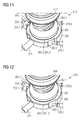
- FIG. 10 shows the next intermediate state, in which the braking force F B has increased until the toothed face 261 . 2 has lifted from the toothed face 262 . 2 .
- the brake cylinder pressure Cp B has been increased further, resulting in the brake piston 244 moving further out according to the brake caliper stiffness.
- the locking wheel 262 and the threaded spindle 261 have not been able to rotate any further. Consequently, the brake piston 244 pulls on the threaded spindle 261 such that the force of the preloaded spring 272 is overcome.
- the toothed face 261 . 2 begins to separate from the toothed face 262 . 2 .
- the separation process is a movement which results from the combination of an axial movement and a rotation of the threaded spindle.
- FIG. 11 shows the next intermediate state, in which the braking force F B has increased to the extent that the toothed face 261 . 2 has notched forward relative to the toothed face 262 . 2 , and in which the arresting pawl 253 . 1 of the locking piston 253 has subsequently sunk into the locking groove 262 . 5 of the locking wheel 262 .
- the brake cylinder pressure Cp B was therefore increased further.
- the threaded spindle 261 continued to experience the combination of axial lifting and rotation, until the tooth tips of the toothed faces 261 . 2 , 262 . 2 were directly opposed. In the next instant, the toothed face 261 . 2 suddenly jumped into the next tooth gap of the toothed face 262 .
- FIG. 12 shows the final state for the parking brake, in which the arresting means 158 (i.e. the mechanical arresting device for the parking brake) is active.
- the brake cylinder pressure Cp B has therefore been decreased, and the brake piston 244 moved back until its backward movement was blocked by the locking bolt 253 .
- the brake unit has no external hydraulic interfaces and therefore no hydraulic line, tube or hose connections to the vehicle.
- the only external interfaces from the brake unit to the vehicle or to the brake controller are those interfaces which are used for the voltage supply or the transfer of signals.
- the integrated hydraulic circuit therefore allows actively regulated service braking, emergency braking or quick-action braking by providing the regulated braking force F B , a hydraulically and/or mechanically actuated and arrestable parking brake function, and passive emergency braking by providing the passive emergency braking force F N .
- the adjustment and wear-related readjustment of the clearance L is realized in a structurally simple manner, and the moving parts are located in the hydraulic medium in this case, thereby reducing the danger of jamming and wear of said moving parts.
- a released brake is reliably detected by means of a distance sensor 171 and/or the switch 271 . Furthermore, a brake which is stuck can be detected by means of the sensor entity 31 .
- a brake system 8 can be realized which is retardation-regulated and which also offers braking distance reliability during operation.
- the inventive brake unit can easily be adapted in a project-specific manner by means of parameterizing characteristic braking values, and therefore a high degree of standardization can be achieved using this brake unit.
Landscapes
- Engineering & Computer Science (AREA)
- Mechanical Engineering (AREA)
- General Engineering & Computer Science (AREA)
- Transportation (AREA)
- Braking Arrangements (AREA)
- Braking Systems And Boosters (AREA)
Applications Claiming Priority (4)
| Application Number | Priority Date | Filing Date | Title |
|---|---|---|---|
| DE102013201635.2A DE102013201635A1 (de) | 2013-01-31 | 2013-01-31 | Bremseinheit für ein Fahrzeug und Fahrzeug mit einer derartigen Bremseinheit |
| DE102013201635 | 2013-01-31 | ||
| DE102013201635.2 | 2013-01-31 | ||
| PCT/EP2014/050232 WO2014117969A1 (de) | 2013-01-31 | 2014-01-08 | Bremseinheit für ein fahrzeug und fahrzeug mit einer derartigen bremseinheit |
Publications (2)
| Publication Number | Publication Date |
|---|---|
| US20150367870A1 US20150367870A1 (en) | 2015-12-24 |
| US9586602B2 true US9586602B2 (en) | 2017-03-07 |
Family
ID=49998229
Family Applications (1)
| Application Number | Title | Priority Date | Filing Date |
|---|---|---|---|
| US14/765,065 Expired - Fee Related US9586602B2 (en) | 2013-01-31 | 2014-01-08 | Brake unit for a vehicle and vehicle having such a brake unit |
Country Status (10)
| Country | Link |
|---|---|
| US (1) | US9586602B2 (zh) |
| EP (1) | EP2934975B1 (zh) |
| CN (1) | CN104955696B (zh) |
| AU (1) | AU2014211685A1 (zh) |
| DE (1) | DE102013201635A1 (zh) |
| ES (1) | ES2629206T3 (zh) |
| PL (1) | PL2934975T3 (zh) |
| RU (1) | RU2015136847A (zh) |
| WO (1) | WO2014117969A1 (zh) |
| ZA (1) | ZA201504513B (zh) |
Families Citing this family (10)
| Publication number | Priority date | Publication date | Assignee | Title |
|---|---|---|---|---|
| DE102017101028A1 (de) | 2017-01-19 | 2018-07-19 | Knorr-Bremse Systeme für Schienenfahrzeuge GmbH | Bremszangeneinheit |
| DE102018214353A1 (de) * | 2018-08-24 | 2020-02-27 | Robert Bosch Gmbh | Verfahren zum Abbau eines vorherrschenden Bremsdrucks in einem Bremskreis einer elektronisch schlupfregelbaren Fremdkraftbremsanlage sowie elektronisch schlupfregelbare Fremdkraftbremsanlage |
| DE102018216976A1 (de) * | 2018-10-04 | 2020-04-09 | Robert Bosch Gmbh | Hydraulikaggregat für eine hydraulische Fahrzeugbremsanlage |
| DE102019103661A1 (de) * | 2019-02-13 | 2020-08-13 | Wabco Europe Bvba | Druckluftbremsanlage eines Kraftfahrzeugs |
| CN111907497B (zh) * | 2020-08-14 | 2022-11-18 | 中车齐齐哈尔车辆有限公司 | 一种集成制动装置及具有其的铁路货车 |
| IT202100022442A1 (it) * | 2021-08-27 | 2023-02-27 | Faiveley Transport Italia Spa | Sistema per determinare la velocità di avanzamento di almeno un veicolo |
| DE102022203763A1 (de) * | 2022-04-13 | 2023-10-19 | Knorr-Bremse Systeme für Schienenfahrzeuge GmbH | Bremssystem und Bremsverfahren für Schienenfahrzeuge |
| DE102022203764A1 (de) * | 2022-04-13 | 2023-10-19 | Knorr-Bremse Systeme für Schienenfahrzeuge GmbH | Bremssystem und Bremsverfahren für Schienenfahrzeuge |
| DE102022203766B4 (de) * | 2022-04-13 | 2024-03-21 | Knorr-Bremse Systeme für Schienenfahrzeuge GmbH | Bremssystem und Bremsverfahren für Schienenfahrzeuge |
| DE102022203767A1 (de) * | 2022-04-13 | 2023-10-19 | Knorr-Bremse Systeme für Schienenfahrzeuge GmbH | Bremssystem und Bremsverfahren für Schienenfahrzeuge |
Citations (9)
| Publication number | Priority date | Publication date | Assignee | Title |
|---|---|---|---|---|
| DE1755343A1 (de) | 1968-04-27 | 1971-08-26 | Hans Bortsch | Kraftfahrzeug mit Feststellbremse |
| DE2810445A1 (de) | 1978-03-10 | 1979-09-13 | Knorr Bremse Gmbh | Bremszylinder |
| US4319671A (en) | 1980-06-02 | 1982-03-16 | Wabco, Ltd. | Hydro-pneumatic brake actuator arranged to maintain a constant brake shoe clearance |
| US4706786A (en) * | 1985-01-25 | 1987-11-17 | Knorr-Bremse Ag | Brake linkage for vehicle brakes |
| US5103940A (en) * | 1989-04-28 | 1992-04-14 | Meneut Jean Claude | Self-adjusting brake incorporating wear compensation |
| DE10329694A1 (de) | 2002-09-17 | 2004-04-01 | Continental Teves Ag & Co. Ohg | Hydraulische Fahrzeugbremse |
| DE102006007684A1 (de) | 2006-02-20 | 2007-08-23 | Bpw Bergische Achsen Kg | Radbremse |
| US20080087505A1 (en) * | 2006-10-13 | 2008-04-17 | Jacob Kobelt | Adjustable cam actuated brake assembly |
| US7434669B2 (en) | 2002-09-17 | 2008-10-14 | Continental Teves Ag & Co. Ohg | Hydraulic vehicle brake |
-
2013
- 2013-01-31 DE DE102013201635.2A patent/DE102013201635A1/de not_active Withdrawn
-
2014
- 2014-01-08 WO PCT/EP2014/050232 patent/WO2014117969A1/de active Application Filing
- 2014-01-08 ES ES14700825.4T patent/ES2629206T3/es active Active
- 2014-01-08 US US14/765,065 patent/US9586602B2/en not_active Expired - Fee Related
- 2014-01-08 PL PL14700825T patent/PL2934975T3/pl unknown
- 2014-01-08 RU RU2015136847A patent/RU2015136847A/ru not_active Application Discontinuation
- 2014-01-08 EP EP14700825.4A patent/EP2934975B1/de active Active
- 2014-01-08 CN CN201480006838.XA patent/CN104955696B/zh active Active
- 2014-01-08 AU AU2014211685A patent/AU2014211685A1/en not_active Abandoned
-
2015
- 2015-06-23 ZA ZA2015/04513A patent/ZA201504513B/en unknown
Patent Citations (9)
| Publication number | Priority date | Publication date | Assignee | Title |
|---|---|---|---|---|
| DE1755343A1 (de) | 1968-04-27 | 1971-08-26 | Hans Bortsch | Kraftfahrzeug mit Feststellbremse |
| DE2810445A1 (de) | 1978-03-10 | 1979-09-13 | Knorr Bremse Gmbh | Bremszylinder |
| US4319671A (en) | 1980-06-02 | 1982-03-16 | Wabco, Ltd. | Hydro-pneumatic brake actuator arranged to maintain a constant brake shoe clearance |
| US4706786A (en) * | 1985-01-25 | 1987-11-17 | Knorr-Bremse Ag | Brake linkage for vehicle brakes |
| US5103940A (en) * | 1989-04-28 | 1992-04-14 | Meneut Jean Claude | Self-adjusting brake incorporating wear compensation |
| DE10329694A1 (de) | 2002-09-17 | 2004-04-01 | Continental Teves Ag & Co. Ohg | Hydraulische Fahrzeugbremse |
| US7434669B2 (en) | 2002-09-17 | 2008-10-14 | Continental Teves Ag & Co. Ohg | Hydraulic vehicle brake |
| DE102006007684A1 (de) | 2006-02-20 | 2007-08-23 | Bpw Bergische Achsen Kg | Radbremse |
| US20080087505A1 (en) * | 2006-10-13 | 2008-04-17 | Jacob Kobelt | Adjustable cam actuated brake assembly |
Also Published As
| Publication number | Publication date |
|---|---|
| PL2934975T3 (pl) | 2017-09-29 |
| CN104955696A (zh) | 2015-09-30 |
| AU2014211685A1 (en) | 2015-07-16 |
| DE102013201635A1 (de) | 2014-07-31 |
| US20150367870A1 (en) | 2015-12-24 |
| EP2934975B1 (de) | 2017-03-22 |
| ZA201504513B (en) | 2016-05-25 |
| ES2629206T3 (es) | 2017-08-07 |
| EP2934975A1 (de) | 2015-10-28 |
| CN104955696B (zh) | 2017-07-07 |
| WO2014117969A1 (de) | 2014-08-07 |
| RU2015136847A (ru) | 2017-03-10 |
Similar Documents
| Publication | Publication Date | Title |
|---|---|---|
| US9586602B2 (en) | Brake unit for a vehicle and vehicle having such a brake unit | |
| US20150367822A1 (en) | Brake unit for a Vehicle and Vehicle having such a Brake Unit | |
| US20150367826A1 (en) | Brake unit for a vehicle and vehicle with a brake unit of this type | |
| US4018140A (en) | Hydraulic disc brake actuator | |
| AU2010202131B2 (en) | Combination cylinder with power-transmitting transmission having variable gear ratio | |
| KR101237672B1 (ko) | 철도차량용 디스크 브레이크 유닛 | |
| US7413061B2 (en) | Method and device for controlling an electrically actuated wear adjuster | |
| CS207356B2 (en) | Hydraulic control facility of the vehicle brake | |
| EP3271602B1 (en) | Brake actuator | |
| US3954304A (en) | Emergency and handbrake control system | |
| US9989117B2 (en) | Disc brake having a bidirectional wear adjustment device and bidirectional wear adjustment device | |
| US9656679B2 (en) | Brake unit for a vehicle and vehicle having such a brake unit | |
| CA2977880A1 (en) | Parking brake arrangement | |
| US3557915A (en) | Brake shoe adjusting mechanism for a railway vehicle braking unit | |
| KR101845336B1 (ko) | 제어효율 향상 및 수동 제동완해기능을 갖는 철도차량용 전기기계식 제동엑츄에이터 | |
| US3842951A (en) | Two way automatic brake adjuster | |
| DE2028540B2 (de) | Druckmittelbeaufschlagbarer bremszylinder, insbesondere fuer hydraulisch betaetigte klotz- oder scheibenbremse von schienenfahrzeugen | |
| WO2016064424A1 (en) | Slack adjuster for narrow gauge railroad cars |
Legal Events
| Date | Code | Title | Description |
|---|---|---|---|
| AS | Assignment |
Owner name: LIEBHERR-TRANSPORTATION SYSTEMS GMBH & CO. KG, AUS Free format text: ASSIGNMENT OF ASSIGNORS INTEREST;ASSIGNORS:BILDSTEIN, MARKUS;GAILE, ANTON;REEL/FRAME:036777/0361 Effective date: 20151001 Owner name: SIEMENS AKTIENGESELLSCHAFT, GERMANY Free format text: ASSIGNMENT OF ASSIGNORS INTEREST;ASSIGNOR:SCHIFFERS, TONI;REEL/FRAME:036777/0406 Effective date: 20150611 |
|
| AS | Assignment |
Owner name: SIEMENS AKTIENGESELLSCHAFT, GERMANY Free format text: ASSIGNMENT OF ASSIGNORS INTEREST;ASSIGNOR:LIEBHERR-TRANSPORTATION SYSTEMS GMBH & CO. KG;REEL/FRAME:036792/0378 Effective date: 20150930 |
|
| STCF | Information on status: patent grant |
Free format text: PATENTED CASE |
|
| FEPP | Fee payment procedure |
Free format text: MAINTENANCE FEE REMINDER MAILED (ORIGINAL EVENT CODE: REM.); ENTITY STATUS OF PATENT OWNER: LARGE ENTITY |
|
| LAPS | Lapse for failure to pay maintenance fees |
Free format text: PATENT EXPIRED FOR FAILURE TO PAY MAINTENANCE FEES (ORIGINAL EVENT CODE: EXP.); ENTITY STATUS OF PATENT OWNER: LARGE ENTITY |
|
| STCH | Information on status: patent discontinuation |
Free format text: PATENT EXPIRED DUE TO NONPAYMENT OF MAINTENANCE FEES UNDER 37 CFR 1.362 |
|
| FP | Lapsed due to failure to pay maintenance fee |
Effective date: 20210307 |