US9573101B2 - Micro-bubble generator for showerhead - Google Patents
Micro-bubble generator for showerhead Download PDFInfo
- Publication number
- US9573101B2 US9573101B2 US14/700,171 US201514700171A US9573101B2 US 9573101 B2 US9573101 B2 US 9573101B2 US 201514700171 A US201514700171 A US 201514700171A US 9573101 B2 US9573101 B2 US 9573101B2
- Authority
- US
- United States
- Prior art keywords
- housing
- generating means
- micro
- bubble generating
- bubble generator
- Prior art date
- Legal status (The legal status is an assumption and is not a legal conclusion. Google has not performed a legal analysis and makes no representation as to the accuracy of the status listed.)
- Expired - Fee Related, expires
Links
Images


Classifications
-
- B—PERFORMING OPERATIONS; TRANSPORTING
- B01—PHYSICAL OR CHEMICAL PROCESSES OR APPARATUS IN GENERAL
- B01F—MIXING, e.g. DISSOLVING, EMULSIFYING OR DISPERSING
- B01F25/00—Flow mixers; Mixers for falling materials, e.g. solid particles
- B01F25/40—Static mixers
- B01F25/42—Static mixers in which the mixing is affected by moving the components jointly in changing directions, e.g. in tubes provided with baffles or obstructions
- B01F25/43—Mixing tubes, e.g. wherein the material is moved in a radial or partly reversed direction
- B01F25/432—Mixing tubes, e.g. wherein the material is moved in a radial or partly reversed direction with means for dividing the material flow into separate sub-flows and for repositioning and recombining these sub-flows; Cross-mixing, e.g. conducting the outer layer of the material nearer to the axis of the tube or vice-versa
- B01F25/4323—Mixing tubes, e.g. wherein the material is moved in a radial or partly reversed direction with means for dividing the material flow into separate sub-flows and for repositioning and recombining these sub-flows; Cross-mixing, e.g. conducting the outer layer of the material nearer to the axis of the tube or vice-versa using elements provided with a plurality of channels or using a plurality of tubes which can either be placed between common spaces or collectors
-
- B01F5/0644—
-
- B—PERFORMING OPERATIONS; TRANSPORTING
- B01—PHYSICAL OR CHEMICAL PROCESSES OR APPARATUS IN GENERAL
- B01F—MIXING, e.g. DISSOLVING, EMULSIFYING OR DISPERSING
- B01F23/00—Mixing according to the phases to be mixed, e.g. dispersing or emulsifying
- B01F23/20—Mixing gases with liquids
- B01F23/23—Mixing gases with liquids by introducing gases into liquid media, e.g. for producing aerated liquids
- B01F23/232—Mixing gases with liquids by introducing gases into liquid media, e.g. for producing aerated liquids using flow-mixing means for introducing the gases, e.g. baffles
- B01F23/2323—Mixing gases with liquids by introducing gases into liquid media, e.g. for producing aerated liquids using flow-mixing means for introducing the gases, e.g. baffles by circulating the flow in guiding constructions or conduits
-
- B01F3/04503—
-
- B—PERFORMING OPERATIONS; TRANSPORTING
- B05—SPRAYING OR ATOMISING IN GENERAL; APPLYING FLUENT MATERIALS TO SURFACES, IN GENERAL
- B05B—SPRAYING APPARATUS; ATOMISING APPARATUS; NOZZLES
- B05B1/00—Nozzles, spray heads or other outlets, with or without auxiliary devices such as valves, heating means
- B05B1/14—Nozzles, spray heads or other outlets, with or without auxiliary devices such as valves, heating means with multiple outlet openings; with strainers in or outside the outlet opening
- B05B1/18—Roses; Shower heads
- B05B1/185—Roses; Shower heads characterised by their outlet element; Mounting arrangements therefor
-
- B—PERFORMING OPERATIONS; TRANSPORTING
- B05—SPRAYING OR ATOMISING IN GENERAL; APPLYING FLUENT MATERIALS TO SURFACES, IN GENERAL
- B05B—SPRAYING APPARATUS; ATOMISING APPARATUS; NOZZLES
- B05B7/00—Spraying apparatus for discharge of liquids or other fluent materials from two or more sources, e.g. of liquid and air, of powder and gas
- B05B7/02—Spray pistols; Apparatus for discharge
- B05B7/04—Spray pistols; Apparatus for discharge with arrangements for mixing liquids or other fluent materials before discharge
- B05B7/0416—Spray pistols; Apparatus for discharge with arrangements for mixing liquids or other fluent materials before discharge with arrangements for mixing one gas and one liquid
- B05B7/0425—Spray pistols; Apparatus for discharge with arrangements for mixing liquids or other fluent materials before discharge with arrangements for mixing one gas and one liquid without any source of compressed gas, e.g. the air being sucked by the pressurised liquid
-
- E—FIXED CONSTRUCTIONS
- E03—WATER SUPPLY; SEWERAGE
- E03C—DOMESTIC PLUMBING INSTALLATIONS FOR FRESH WATER OR WASTE WATER; SINKS
- E03C1/00—Domestic plumbing installations for fresh water or waste water; Sinks
- E03C1/02—Plumbing installations for fresh water
- E03C1/025—Water supply lines as such, e.g. shower hoses
-
- E—FIXED CONSTRUCTIONS
- E03—WATER SUPPLY; SEWERAGE
- E03C—DOMESTIC PLUMBING INSTALLATIONS FOR FRESH WATER OR WASTE WATER; SINKS
- E03C1/00—Domestic plumbing installations for fresh water or waste water; Sinks
- E03C1/02—Plumbing installations for fresh water
- E03C1/08—Jet regulators or jet guides, e.g. anti-splash devices
- E03C1/084—Jet regulators with aerating means
-
- B—PERFORMING OPERATIONS; TRANSPORTING
- B05—SPRAYING OR ATOMISING IN GENERAL; APPLYING FLUENT MATERIALS TO SURFACES, IN GENERAL
- B05B—SPRAYING APPARATUS; ATOMISING APPARATUS; NOZZLES
- B05B1/00—Nozzles, spray heads or other outlets, with or without auxiliary devices such as valves, heating means
- B05B1/14—Nozzles, spray heads or other outlets, with or without auxiliary devices such as valves, heating means with multiple outlet openings; with strainers in or outside the outlet opening
- B05B1/18—Roses; Shower heads
-
- E—FIXED CONSTRUCTIONS
- E03—WATER SUPPLY; SEWERAGE
- E03C—DOMESTIC PLUMBING INSTALLATIONS FOR FRESH WATER OR WASTE WATER; SINKS
- E03C1/00—Domestic plumbing installations for fresh water or waste water; Sinks
- E03C1/02—Plumbing installations for fresh water
- E03C1/04—Water-basin installations specially adapted to wash-basins or baths
- E03C1/0408—Water installations especially for showers
- E03C1/0409—Shower handles
Definitions
- the present invention relates to a micro-bubble generator and more particularly pertains to a micro-bubble generator for showerhead.
- the present invention provides a micro-bubble generator for showerhead which is simple in structure and capable of producing micro-bubbles which are about 1.5 microns in diameter.
- the present invention generally comprises:
- a housing having a water inlet at a first end thereof, a water outlet at a second end thereof, and a plurality of apertures provided circumferentially around a lateral surface of the housing;
- a bubble generating means securedly received within the housing and having a top which is engaged with an inner wall of the housing in a watertight manner, a body positioned downstream from the top and having a diameter smaller than diameter of the inner wall of the housing so that a circumferential gap is formed between an outer lateral surface of the body and the inner wall of the housing, and a recess coaxially extending from the top to a portion of the body, wherein a plurality of water passages extend radially outward from the recess to the outer lateral surface of the body so that each of the water passages is in communication with the circumferential gap;
- a sealing means disposed between the housing and the bubble generating means which provides selective communication from the plurality of apertures to the top of the bubble generating means.
- the circumferential gap is approximately 0.5 mm in width.
- Each of the water passages is approximately 1.5 mm to 2.0 mm in diameter.
- the body of the bubble generating means is tapered inwards at a downstream end thereof to help reduce pressure of water flowing from the circumferential gap and to allow micro-bubbles in water flowing from the circumferential gap to disperse evenly.
- a mounting bracket is provided upstream of the bubble generating means, and the mounting bracket is fixedly positioned in relation to the housing so as to leave a gap between the housing and the mounting bracket, and the gap provides communication between the plurality of apertures and the top of the bubble generating means;
- the sealing means is in form of an annular ring having an outer downward extending flange portion and an inner upward extending flange portion; the outer downward extending flange portion is securedly disposed at the gap between the housing and the mounting bracket in a way to seal an end of the gap; the inner upward extending flange portion is disposed towards an other end of the gap and movable between a sealing position where it blocks communication from the plurality of apertures to the top of the bubble generating means and a non-sealing position where it allows communication from the plurality of apertures to the top of the bubble generating means.
- a connector having a first portion, a second portion and a bore therethrough; the first portion is threadedly engaged with a downstream end of the housing, and the second portion has a threaded external wall for threadedly engaging with a downstream water pipe.
- the connector is also provided with upward extending protrusions abutting against a downstream end of the body of the bubble generating means for supporting the bubble generating means in position.
- the upstream end of the housing is internally threaded for engaging with an upstream water pipe.
- the housing is made of plastics or copper.
- the bubble generating means is made of copper or plastics.
- FIG. 1 is a cross sectional view of a preferred embodiment of the present invention.
- FIG. 2 is a disassembling view of the embodiment of the present invention as shown in FIG. 1 .
- FIG. 3 is a perspective view of the bubble generating means of the embodiment of the present invention as shown in FIG. 1 .
- FIG. 4 is an enlarged cross sectional view showing the sealing means in the sealing position of the embodiment of the present invention as shown in FIG. 1 .
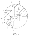
- FIG. 5 is an enlarged cross sectional view showing the sealing means in the non-sealing position of the embodiment of the present invention as shown in FIG. 1 .
- the present embodiment comprises a housing 1 , a bubble generating means 2 and a sealing means 3 .
- the housing 1 has a water inlet 11 at a first end thereof, a water outlet 12 at a second end thereof, and a plurality of apertures 13 provided circumferentially around a lateral surface of the housing 1 .
- the bubble generating means 2 is securedly received within the housing 1 and has a top 21 which is engaged with an inner wall 14 of the housing 1 in a watertight manner by means of an O-ring 6 , a body 22 positioned downstream from the top 21 and having a diameter smaller than diameter of the inner wall 14 of the housing so that a circumferential gap 23 is formed between an outer lateral surface 24 of the body 22 and the inner wall 14 of the housing 1 , and a recess 25 coaxially extending from the top 21 to a portion of the body 22 , wherein a plurality of water passages 26 extend radially outward from the recess 25 to the outer lateral surface 24 of the body 22 so that each of the water passages 26 is in communication with the circumferential gap 23 .
- the circumferential gap 23 is approximately 0.5 mm in width.
- Each of the water passages 26 is approximately 1.5 mm to 2.0 mm in diameter.
- the body 22 of the bubble generating means 2 is tapered inwards at a downstream end thereof.
- a mounting bracket 4 is provided upstream of the bubble generating means 2 , and the mounting bracket 4 is fixedly positioned in relation to the housing 1 so as to leave a gap 41 between the housing 1 and the mounting bracket 4 , and the gap 41 provides communication between the plurality of apertures 13 and the top 21 of the bubble generating means 2 .
- the sealing means 3 is in form of an annular ring having an outer downward extending flange portion 31 and an inner upward extending flange portion 32 . The outer downward extending flange portion 31 is securedly disposed at the gap 41 between the housing 1 and the mounting bracket 4 in a way to seal an end of the gap 41 .
- the inner upward extending flange portion 42 is disposed towards an other end of the gap 41 and movable between a sealing position where it blocks communication from the plurality of apertures 13 to the top 21 of the bubble generating means 2 and a non-sealing position where it allows communication from the plurality of apertures 13 to the top 21 of the bubble generating means 2 .
- a connector 5 having a first portion 51 , a second portion 52 and a bore 53 therethrough is provided.
- the first portion 51 is threadedly engaged with a downstream end of the housing 1
- the second portion 52 has a threaded external wall 54 for threadedly engaging with a downstream water pipe.
- the connector 5 is also provided with upward extending protrusions 55 abutting against a downstream end of the body 22 of the bubble generating means 2 for supporting the bubble generating means 2 in position.
- the upstream end of the housing 1 is internally threaded for engaging with an upstream water pipe.
- the connector 5 is water-sealingly engaged with the housing by means of an O-ring 7 .
- the housing 1 is made of plastics, but it could also be made of copper; the bubble generating means 2 is made of copper, but it could also be made of plastics.
- air in the recess 25 is drawn to the water passages 26 , air pressure in the recess 25 is reduced, thus puling the sealing means 3 to the non-sealing position to allow surrounding air to be drawn from the plurality of apertures 13 to refill the recess 25 , so that water passing through the water passages 26 always has sufficient amount of air to become aerated.
- the aerated water then plunges onto the inner wall 14 of the housing 1 and exit through the circumferential gap 23 .
- the circumferential gap 23 is very narrow, any water bubbles formed in the water passages 26 would be broken up into micro-bubbles.
- the inward tapering of the body 22 of the bubble generating means 2 at a downstream end thereof also helps reduce pressure of water flowing from the circumferential gap 23 and to allow micro-bubbles in water flowing from the circumferential gap 23 to disperse evenly. Therefore, the bubbles in the water stream exiting from the circumferential gap 23 and thereafter the water outlet 12 of the housing 1 are micro in size.
- the above embodiment is a preferred embodiment of the present invention.
- the present invention is capable of other embodiments and is not limited by the above embodiment. Any other variation, decoration, substitution, combination or simplification, whether in substance or in principle, not deviated from the spirit of the present invention, is replacement or substitution of equivalent effect and falls within the scope of protection of the present invention.
Abstract
Description
Claims (10)
Priority Applications (1)
| Application Number | Priority Date | Filing Date | Title |
|---|---|---|---|
| US14/700,171 US9573101B2 (en) | 2015-04-30 | 2015-04-30 | Micro-bubble generator for showerhead |
Applications Claiming Priority (1)
| Application Number | Priority Date | Filing Date | Title |
|---|---|---|---|
| US14/700,171 US9573101B2 (en) | 2015-04-30 | 2015-04-30 | Micro-bubble generator for showerhead |
Publications (2)
| Publication Number | Publication Date |
|---|---|
| US20160317987A1 US20160317987A1 (en) | 2016-11-03 |
| US9573101B2 true US9573101B2 (en) | 2017-02-21 |
Family
ID=57203961
Family Applications (1)
| Application Number | Title | Priority Date | Filing Date |
|---|---|---|---|
| US14/700,171 Expired - Fee Related US9573101B2 (en) | 2015-04-30 | 2015-04-30 | Micro-bubble generator for showerhead |
Country Status (1)
| Country | Link |
|---|---|
| US (1) | US9573101B2 (en) |
Families Citing this family (3)
| Publication number | Priority date | Publication date | Assignee | Title |
|---|---|---|---|---|
| DE202016007178U1 (en) * | 2016-11-23 | 2018-02-27 | Neoperl Gmbh | Sanitary outlet unit |
| JP7295669B2 (en) * | 2019-03-22 | 2023-06-21 | 日東精工株式会社 | shower head |
| CN112705060B (en) * | 2020-12-15 | 2021-12-28 | 燕山大学 | Rotary multi-diameter bubble generating device |
Citations (7)
| Publication number | Priority date | Publication date | Assignee | Title |
|---|---|---|---|---|
| US20050077636A1 (en) * | 2003-10-10 | 2005-04-14 | Bortkevitch Sergey V. | Method and apparatus for enhanced oil recovery by injection of a micro-dispersed gas-liquid mixture into the oil-bearing formation |
| US20060027100A1 (en) * | 2003-06-13 | 2006-02-09 | Five Star Technologies, Inc. | Device and method for generating micro bubbles in a liquid using hydrodynamic cavitation |
| US20070257381A1 (en) * | 2006-05-08 | 2007-11-08 | Chuang Shuo W | Cavitation generating system |
| US7758024B2 (en) * | 2005-11-11 | 2010-07-20 | Shoei Butsuryu Co., Ltd. | Microbubble generating device and hair washing device utilizing the same |
| US7913984B2 (en) * | 2004-05-31 | 2011-03-29 | Sanyo Facilities Industry Co., Ltd. | Method and system for generating microbubble-contained liquid and microbubble generator to be assembled in the system |
| US20130168879A1 (en) * | 2012-01-04 | 2013-07-04 | Chun-Hsin Lee | Venturi tube for shower head |
| US20140264966A1 (en) * | 2001-11-26 | 2014-09-18 | Thomas D. Gillette | Systems and methods for producing ozonated water on demand |
-
2015
- 2015-04-30 US US14/700,171 patent/US9573101B2/en not_active Expired - Fee Related
Patent Citations (7)
| Publication number | Priority date | Publication date | Assignee | Title |
|---|---|---|---|---|
| US20140264966A1 (en) * | 2001-11-26 | 2014-09-18 | Thomas D. Gillette | Systems and methods for producing ozonated water on demand |
| US20060027100A1 (en) * | 2003-06-13 | 2006-02-09 | Five Star Technologies, Inc. | Device and method for generating micro bubbles in a liquid using hydrodynamic cavitation |
| US20050077636A1 (en) * | 2003-10-10 | 2005-04-14 | Bortkevitch Sergey V. | Method and apparatus for enhanced oil recovery by injection of a micro-dispersed gas-liquid mixture into the oil-bearing formation |
| US7913984B2 (en) * | 2004-05-31 | 2011-03-29 | Sanyo Facilities Industry Co., Ltd. | Method and system for generating microbubble-contained liquid and microbubble generator to be assembled in the system |
| US7758024B2 (en) * | 2005-11-11 | 2010-07-20 | Shoei Butsuryu Co., Ltd. | Microbubble generating device and hair washing device utilizing the same |
| US20070257381A1 (en) * | 2006-05-08 | 2007-11-08 | Chuang Shuo W | Cavitation generating system |
| US20130168879A1 (en) * | 2012-01-04 | 2013-07-04 | Chun-Hsin Lee | Venturi tube for shower head |
Also Published As
| Publication number | Publication date |
|---|---|
| US20160317987A1 (en) | 2016-11-03 |
Similar Documents
| Publication | Publication Date | Title |
|---|---|---|
| US10695726B2 (en) | Micro-bubble generator | |
| US9573101B2 (en) | Micro-bubble generator for showerhead | |
| US9211357B1 (en) | Pump type aroma diffuser | |
| CN108571037B (en) | Sanitary insert unit | |
| US11248368B2 (en) | Faucet aerator with center stream | |
| WO2017029835A1 (en) | Foamy water discharging device and foamy water discharging unit | |
| US20130082122A1 (en) | Jet regulator | |
| KR101581391B1 (en) | Venturi structure shower nozzle | |
| JP7249819B2 (en) | Microbubble generating nozzle | |
| CN109073116B (en) | Faucet coupling with flow stability | |
| CN107303543A (en) | Shower nozzle | |
| JP6199768B2 (en) | Bubble generator and bubble generation mechanism | |
| EA202090156A1 (en) | BARBOTING DEVICE AND METHOD FOR PARTICLE RECOVERY | |
| RU2563744C1 (en) | Atomiser with active spreader | |
| TW200520851A (en) | Foam nozzle | |
| CN105546211B (en) | Flow regulator and water economizer and flow regulator | |
| MX2019006669A (en) | Gas-liquid separation device. | |
| RU93704U1 (en) | GAS-LIQUID INJECTOR | |
| RU2554335C1 (en) | Swirl atomiser | |
| US9974709B2 (en) | Nozzles | |
| RU2652002C1 (en) | Pneumatic nozzle with two-phase flow of spray | |
| MX2018004964A (en) | Nozzle useful for shower systems. | |
| RU2631282C1 (en) | Complex atomizer | |
| JP2014083411A (en) | Shower head | |
| RU2554336C1 (en) | Atomiser |
Legal Events
| Date | Code | Title | Description |
|---|---|---|---|
| AS | Assignment |
Owner name: AQUAMATE K&B LIMITED, HONG KONG Free format text: ASSIGNMENT OF ASSIGNORS INTEREST;ASSIGNOR:LEE, RANSOM MAN PAN;REEL/FRAME:040833/0498 Effective date: 20150430 |
|
| STCF | Information on status: patent grant |
Free format text: PATENTED CASE |
|
| FEPP | Fee payment procedure |
Free format text: MAINTENANCE FEE REMINDER MAILED (ORIGINAL EVENT CODE: REM.); ENTITY STATUS OF PATENT OWNER: MICROENTITY |
|
| LAPS | Lapse for failure to pay maintenance fees |
Free format text: PATENT EXPIRED FOR FAILURE TO PAY MAINTENANCE FEES (ORIGINAL EVENT CODE: EXP.); ENTITY STATUS OF PATENT OWNER: MICROENTITY |
|
| STCH | Information on status: patent discontinuation |
Free format text: PATENT EXPIRED DUE TO NONPAYMENT OF MAINTENANCE FEES UNDER 37 CFR 1.362 |
|
| FP | Lapsed due to failure to pay maintenance fee |
Effective date: 20210221 |