US956754A - Coin-controlled telephone. - Google Patents
Coin-controlled telephone. Download PDFInfo
- Publication number
- US956754A US956754A US51689209A US1909516892A US956754A US 956754 A US956754 A US 956754A US 51689209 A US51689209 A US 51689209A US 1909516892 A US1909516892 A US 1909516892A US 956754 A US956754 A US 956754A
- Authority
- US
- United States
- Prior art keywords
- coin
- telephone
- controlled telephone
- plates
- toll
- Prior art date
- Legal status (The legal status is an assumption and is not a legal conclusion. Google has not performed a legal analysis and makes no representation as to the accuracy of the status listed.)
- Expired - Lifetime
Links
- 238000010276 construction Methods 0.000 description 3
- 210000005069 ears Anatomy 0.000 description 2
- 230000015572 biosynthetic process Effects 0.000 description 1
Images
Classifications
-
- G—PHYSICS
- G07—CHECKING-DEVICES
- G07D—HANDLING OF COINS OR VALUABLE PAPERS, e.g. TESTING, SORTING BY DENOMINATIONS, COUNTING, DISPENSING, CHANGING OR DEPOSITING
- G07D5/00—Testing specially adapted to determine the identity or genuineness of coins, e.g. for segregating coins which are unacceptable or alien to a currency
Definitions
- This invention relates to toll collecting devices for telephone and electric light substations, and particularly, is adapted for subscribers sub-stations where a certain toll is paid each month.
- the object of the invention is to provide a device of this character in which the circuits of the sub-station apparatus are incomplete until the proper toll has been deposited, and further means for adjusting the device whereby any differences in toll rates may be accounted for.
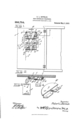
- Figure l is an elevation of the rear face of a sub-station box door, showing my invention applied thereto;
- Fig. 2 is a section taken on the line 22 of Fig. 1;
- Fig. 3 is a detail elevation of one of the base plates;
- Fig. 4 is a detail perspective view of one of the contact plates.
- 1 denotes the door of the telephone or electric light box, which is shown as having attached to its rear face separated base plates 2 and 3, each provided with slots 4, in either end thereof, which lie immediately over similar slots 5 formed in the door.
- clamping and adjusting bolts 6 Positioned in these slots are clamping and adjusting bolts 6 with their heads sliding or moving within the slots 5 in such a manner as to permit their free adjustment from one side of the base plate to the other.
- These bolts (3 pass through apertures formed in the contact plates 7 which have in their outer flanges S a cut-away portion 9 which is bent up to form a suitable tongue 10 in which a binding screw 11 is secured.
- the contact plates are substantially Z- shaped in formation with a flange 12 lying in a parallel plane to the flange 8 in such a manner that the contact plate on one side is adapted to have its flange 12 overlapping the flange 12 of the opposite contact member, thereby insuring a wide range of adJustment of these parts.
- a socketed base a pair of supporting plates secured to the base and each having separate slots arranged over the sockets in the base, substantially Z-shaped coin testing and retaining members, bolts passing through said members to secure the same independently adjustable on the plates, whereby their lower ends may be held together to form a I In testimony whereof, I have hereunto set restricted opening to permit the passage of my hand in presence of two subscribing wit- 10 coins of certain denominations and to hold nesses.
Landscapes
- Physics & Mathematics (AREA)
- General Physics & Mathematics (AREA)
- Control Of Vending Devices And Auxiliary Devices For Vending Devices (AREA)
Description
' R. L. BOWMAN COIN CONTROLLED TELEPHONE. APPLICATION FILED SEPT. 9, 1909.
Patented May 3, 1910.
1%, I Y M UNITED STATES PATENT GFFICE.
ROBERT LEE BOWMAN, OE KNOXVILLE, TENNESSEE.
COIN-CONTROLLED TELEPHONE.
To all whom it may concern:
Be it known that I, ROBERT LEE BOWMAN, a citizen of the United States, residing at Knoxville, Tennessee, have invented certain new and useful Improvements in Coin-Controlled Telephones; and I do declare the following to be a full, clear, and exact description of the invention, such as will enable others skilled in the art to which it appertains to make and use the same.
This invention relates to toll collecting devices for telephone and electric light substations, and particularly, is adapted for subscribers sub-stations where a certain toll is paid each month.
The object of the invention is to provide a device of this character in which the circuits of the sub-station apparatus are incomplete until the proper toll has been deposited, and further means for adjusting the device whereby any differences in toll rates may be accounted for.
With the foregoing and other objects in view, the invention consists of certain novel features of construction, combination and arrangement of parts, as will be more fully described and particularly pointed out in the appended claim.
In the drawings, Figure l is an elevation of the rear face of a sub-station box door, showing my invention applied thereto; Fig. 2 is a section taken on the line 22 of Fig. 1; Fig. 3 is a detail elevation of one of the base plates; Fig. 4 is a detail perspective view of one of the contact plates.
Referring more especially to the drawings, 1 denotes the door of the telephone or electric light box, which is shown as having attached to its rear face separated base plates 2 and 3, each provided with slots 4, in either end thereof, which lie immediately over similar slots 5 formed in the door. Positioned in these slots are clamping and adjusting bolts 6 with their heads sliding or moving within the slots 5 in such a manner as to permit their free adjustment from one side of the base plate to the other. These bolts (3 pass through apertures formed in the contact plates 7 which have in their outer flanges S a cut-away portion 9 which is bent up to form a suitable tongue 10 in which a binding screw 11 is secured. This Specification of Letters Patent.
Application filed September 9, 1909.
Patented May 3, 1910.
Serial No. 516,892.
constitutes the binding post and alfords a direct connection with the line wires.
The contact plates are substantially Z- shaped in formation with a flange 12 lying in a parallel plane to the flange 8 in such a manner that the contact plate on one side is adapted to have its flange 12 overlapping the flange 12 of the opposite contact member, thereby insuring a wide range of adJustment of these parts. In Fig. 1, I have shown a set of these contact plates arranged at A and connected with one of the line wires L of the telephone or electric light line, another set arranged at B having connection with the set A by the wire 7', The opposite member of the set A is connected by the wire Z to the opposite member of the set B, a suitable wire Z being led off from the opposite member of the set B to the opposite side of the telephone or electric light apparatus, as will be clearly understood by those versed in the art. There may be as many of these sets as are necessary, each succeeding one being arranged for a lesser denomination of coin, than the preceding one above and each one of the sets may be adjusted according to the amount of toll charged for a certain sub station. In the door, immediately above the set A, is a coin slot 13 by which the coins are directed to the sets.
From the foregoing description, taken in connection with the accompanying drawings, the construction and operation of the invention will be readily understood without requiring a more extended explanation.
Various changes in the form, proportion and the minor details of construction may be resorted to without departing from the principle or sacrificing any of the advantages of the invention, as defined in the appended claim.
Having thus described my invention, what I claim is:
In a device of the class described, a socketed base, a pair of supporting plates secured to the base and each having separate slots arranged over the sockets in the base, substantially Z-shaped coin testing and retaining members, bolts passing through said members to secure the same independently adjustable on the plates, whereby their lower ends may be held together to form a I In testimony whereof, I have hereunto set restricted opening to permit the passage of my hand in presence of two subscribing wit- 10 coins of certain denominations and to hold nesses.
coins of the proper denominations ears struck up from the attaching flanges of said members, and binding screws passing through said ears to secure the line terminals to said members.
ROBERT LEE BOWMAN.
"Witnesses VVILLIAM T. DAvIs, L. S. ESTES.
Priority Applications (1)
| Application Number | Priority Date | Filing Date | Title |
|---|---|---|---|
| US51689209A US956754A (en) | 1909-09-09 | 1909-09-09 | Coin-controlled telephone. |
Applications Claiming Priority (1)
| Application Number | Priority Date | Filing Date | Title |
|---|---|---|---|
| US51689209A US956754A (en) | 1909-09-09 | 1909-09-09 | Coin-controlled telephone. |
Publications (1)
| Publication Number | Publication Date |
|---|---|
| US956754A true US956754A (en) | 1910-05-03 |
Family
ID=3025157
Family Applications (1)
| Application Number | Title | Priority Date | Filing Date |
|---|---|---|---|
| US51689209A Expired - Lifetime US956754A (en) | 1909-09-09 | 1909-09-09 | Coin-controlled telephone. |
Country Status (1)
| Country | Link |
|---|---|
| US (1) | US956754A (en) |
-
1909
- 1909-09-09 US US51689209A patent/US956754A/en not_active Expired - Lifetime
Similar Documents
| Publication | Publication Date | Title |
|---|---|---|
| DE2430281A1 (en) | ELECTRICAL SYSTEM COMPOSED FROM POWER DISTRIBUTION BARS | |
| DE69211784T2 (en) | Test probe for electrical contact | |
| US1470747A (en) | Coin collector | |
| US612782A (en) | Iieber r | |
| US1052989A (en) | Rent-collecting means for telephone service. | |
| US2278930A (en) | Coin chute | |
| US1666229A (en) | Device | |
| US922045A (en) | Telephone pay-station. | |
| US1182963A (en) | Attachment for coin-collectors. | |
| US916293A (en) | Coin-holder. | |
| US1039604A (en) | Coin-distributing apparatus. | |
| US1182962A (en) | Coin-collector for telephone-tolls. | |
| US886497A (en) | System and apparatus for telephone local toll or pay stations. | |
| US577911A (en) | Edward p | |
| US1776301A (en) | Coin-controlled apparatus | |
| US2287176A (en) | Telephone coin collector | |
| US1024931A (en) | Meter connection-box. | |
| US1245472A (en) | Coin-collecting device. | |
| US931547A (en) | Rent-collecting means for telephone service. | |
| DE554583C (en) | Device for the detection of high electrical voltages | |
| US1141866A (en) | Telephone pay-station. | |
| US1221191A (en) | Apparatus for checking a number of telephone-calls. | |
| US801186A (en) | Main distributer for telephone-exchanges. | |
| US338263A (en) | Telephonic transmitting apparatus | |
| US547405A (en) | Telephone-toll apparatus |