US9564620B2 - Power storage device - Google Patents
Power storage device Download PDFInfo
- Publication number
- US9564620B2 US9564620B2 US14/383,132 US201314383132A US9564620B2 US 9564620 B2 US9564620 B2 US 9564620B2 US 201314383132 A US201314383132 A US 201314383132A US 9564620 B2 US9564620 B2 US 9564620B2
- Authority
- US
- United States
- Prior art keywords
- battery containing
- containing body
- end portion
- power storage
- battery
- Prior art date
- Legal status (The legal status is an assumption and is not a legal conclusion. Google has not performed a legal analysis and makes no representation as to the accuracy of the status listed.)
- Active, expires
Links
- 238000003780 insertion Methods 0.000 claims abstract description 75
- 230000037431 insertion Effects 0.000 claims abstract description 75
- 230000000903 blocking effect Effects 0.000 claims abstract description 4
- HBBGRARXTFLTSG-UHFFFAOYSA-N Lithium ion Chemical compound [Li+] HBBGRARXTFLTSG-UHFFFAOYSA-N 0.000 claims description 4
- 229910001416 lithium ion Inorganic materials 0.000 claims description 4
- 230000002265 prevention Effects 0.000 description 23
- 238000012423 maintenance Methods 0.000 description 14
- 238000009434 installation Methods 0.000 description 10
- FWIJKWMXNHRSRO-UHFFFAOYSA-N 1-(3-tert-butyl-1-methylpyrazol-5-yl)-3-(4-chlorophenyl)urea Chemical compound CN1N=C(C(C)(C)C)C=C1NC(=O)NC1=CC=C(Cl)C=C1 FWIJKWMXNHRSRO-UHFFFAOYSA-N 0.000 description 9
- 238000007689 inspection Methods 0.000 description 5
- 239000011810 insulating material Substances 0.000 description 5
- 230000000694 effects Effects 0.000 description 4
- 230000002708 enhancing effect Effects 0.000 description 4
- 238000010586 diagram Methods 0.000 description 3
- 229910052751 metal Inorganic materials 0.000 description 3
- 239000002184 metal Substances 0.000 description 3
- 230000037361 pathway Effects 0.000 description 3
- 238000012546 transfer Methods 0.000 description 3
- 230000007423 decrease Effects 0.000 description 2
- 239000008151 electrolyte solution Substances 0.000 description 2
- 230000006870 function Effects 0.000 description 2
- 239000005001 laminate film Substances 0.000 description 2
- 229920006280 packaging film Polymers 0.000 description 2
- 239000012785 packaging film Substances 0.000 description 2
- 229910001220 stainless steel Inorganic materials 0.000 description 2
- 239000010935 stainless steel Substances 0.000 description 2
- XLYOFNOQVPJJNP-UHFFFAOYSA-N water Substances O XLYOFNOQVPJJNP-UHFFFAOYSA-N 0.000 description 2
- 208000032953 Device battery issue Diseases 0.000 description 1
- 230000008901 benefit Effects 0.000 description 1
- 230000005540 biological transmission Effects 0.000 description 1
- 230000008859 change Effects 0.000 description 1
- 238000006243 chemical reaction Methods 0.000 description 1
- 238000013461 design Methods 0.000 description 1
- 238000007599 discharging Methods 0.000 description 1
- 239000000428 dust Substances 0.000 description 1
- 230000005611 electricity Effects 0.000 description 1
- 210000003811 finger Anatomy 0.000 description 1
- 230000017525 heat dissipation Effects 0.000 description 1
- 230000020169 heat generation Effects 0.000 description 1
- 230000006872 improvement Effects 0.000 description 1
- 239000000463 material Substances 0.000 description 1
- 238000000034 method Methods 0.000 description 1
- 238000012986 modification Methods 0.000 description 1
- 230000004048 modification Effects 0.000 description 1
- 238000000465 moulding Methods 0.000 description 1
- 238000010248 power generation Methods 0.000 description 1
- 230000009467 reduction Effects 0.000 description 1
- 230000002787 reinforcement Effects 0.000 description 1
- 230000008439 repair process Effects 0.000 description 1
- 238000004904 shortening Methods 0.000 description 1
- 239000000243 solution Substances 0.000 description 1
- 210000003813 thumb Anatomy 0.000 description 1
- 238000003466 welding Methods 0.000 description 1
Images


Classifications
-
- H—ELECTRICITY
- H01—ELECTRIC ELEMENTS
- H01M—PROCESSES OR MEANS, e.g. BATTERIES, FOR THE DIRECT CONVERSION OF CHEMICAL ENERGY INTO ELECTRICAL ENERGY
- H01M10/00—Secondary cells; Manufacture thereof
- H01M10/42—Methods or arrangements for servicing or maintenance of secondary cells or secondary half-cells
- H01M10/425—Structural combination with electronic components, e.g. electronic circuits integrated to the outside of the casing
- H01M10/4257—Smart batteries, e.g. electronic circuits inside the housing of the cells or batteries
-
- H01M2/1022—
-
- H—ELECTRICITY
- H01—ELECTRIC ELEMENTS
- H01M—PROCESSES OR MEANS, e.g. BATTERIES, FOR THE DIRECT CONVERSION OF CHEMICAL ENERGY INTO ELECTRICAL ENERGY
- H01M10/00—Secondary cells; Manufacture thereof
- H01M10/42—Methods or arrangements for servicing or maintenance of secondary cells or secondary half-cells
- H01M10/425—Structural combination with electronic components, e.g. electronic circuits integrated to the outside of the casing
-
- H01M2/1077—
-
- H—ELECTRICITY
- H01—ELECTRIC ELEMENTS
- H01M—PROCESSES OR MEANS, e.g. BATTERIES, FOR THE DIRECT CONVERSION OF CHEMICAL ENERGY INTO ELECTRICAL ENERGY
- H01M50/00—Constructional details or processes of manufacture of the non-active parts of electrochemical cells other than fuel cells, e.g. hybrid cells
- H01M50/20—Mountings; Secondary casings or frames; Racks, modules or packs; Suspension devices; Shock absorbers; Transport or carrying devices; Holders
- H01M50/204—Racks, modules or packs for multiple batteries or multiple cells
- H01M50/207—Racks, modules or packs for multiple batteries or multiple cells characterised by their shape
- H01M50/211—Racks, modules or packs for multiple batteries or multiple cells characterised by their shape adapted for pouch cells
-
- H—ELECTRICITY
- H01—ELECTRIC ELEMENTS
- H01M—PROCESSES OR MEANS, e.g. BATTERIES, FOR THE DIRECT CONVERSION OF CHEMICAL ENERGY INTO ELECTRICAL ENERGY
- H01M50/00—Constructional details or processes of manufacture of the non-active parts of electrochemical cells other than fuel cells, e.g. hybrid cells
- H01M50/20—Mountings; Secondary casings or frames; Racks, modules or packs; Suspension devices; Shock absorbers; Transport or carrying devices; Holders
- H01M50/271—Lids or covers for the racks or secondary casings
-
- H—ELECTRICITY
- H01—ELECTRIC ELEMENTS
- H01M—PROCESSES OR MEANS, e.g. BATTERIES, FOR THE DIRECT CONVERSION OF CHEMICAL ENERGY INTO ELECTRICAL ENERGY
- H01M50/00—Constructional details or processes of manufacture of the non-active parts of electrochemical cells other than fuel cells, e.g. hybrid cells
- H01M50/20—Mountings; Secondary casings or frames; Racks, modules or packs; Suspension devices; Shock absorbers; Transport or carrying devices; Holders
- H01M50/289—Mountings; Secondary casings or frames; Racks, modules or packs; Suspension devices; Shock absorbers; Transport or carrying devices; Holders characterised by spacing elements or positioning means within frames, racks or packs
- H01M50/291—Mountings; Secondary casings or frames; Racks, modules or packs; Suspension devices; Shock absorbers; Transport or carrying devices; Holders characterised by spacing elements or positioning means within frames, racks or packs characterised by their shape
-
- H—ELECTRICITY
- H01—ELECTRIC ELEMENTS
- H01M—PROCESSES OR MEANS, e.g. BATTERIES, FOR THE DIRECT CONVERSION OF CHEMICAL ENERGY INTO ELECTRICAL ENERGY
- H01M10/00—Secondary cells; Manufacture thereof
- H01M10/05—Accumulators with non-aqueous electrolyte
- H01M10/052—Li-accumulators
- H01M10/0525—Rocking-chair batteries, i.e. batteries with lithium insertion or intercalation in both electrodes; Lithium-ion batteries
-
- H01M2/10—
-
- H01M2/1005—
-
- H01M2/1011—
-
- H01M2/1016—
-
- H01M2/1061—
-
- H—ELECTRICITY
- H01—ELECTRIC ELEMENTS
- H01M—PROCESSES OR MEANS, e.g. BATTERIES, FOR THE DIRECT CONVERSION OF CHEMICAL ENERGY INTO ELECTRICAL ENERGY
- H01M10/00—Secondary cells; Manufacture thereof
- H01M10/42—Methods or arrangements for servicing or maintenance of secondary cells or secondary half-cells
- H01M10/425—Structural combination with electronic components, e.g. electronic circuits integrated to the outside of the casing
- H01M2010/4271—Battery management systems including electronic circuits, e.g. control of current or voltage to keep battery in healthy state, cell balancing
-
- H—ELECTRICITY
- H01—ELECTRIC ELEMENTS
- H01M—PROCESSES OR MEANS, e.g. BATTERIES, FOR THE DIRECT CONVERSION OF CHEMICAL ENERGY INTO ELECTRICAL ENERGY
- H01M2220/00—Batteries for particular applications
- H01M2220/10—Batteries in stationary systems, e.g. emergency power source in plant
-
- H—ELECTRICITY
- H01—ELECTRIC ELEMENTS
- H01M—PROCESSES OR MEANS, e.g. BATTERIES, FOR THE DIRECT CONVERSION OF CHEMICAL ENERGY INTO ELECTRICAL ENERGY
- H01M50/00—Constructional details or processes of manufacture of the non-active parts of electrochemical cells other than fuel cells, e.g. hybrid cells
- H01M50/20—Mountings; Secondary casings or frames; Racks, modules or packs; Suspension devices; Shock absorbers; Transport or carrying devices; Holders
- H01M50/256—Carrying devices, e.g. belts
-
- Y—GENERAL TAGGING OF NEW TECHNOLOGICAL DEVELOPMENTS; GENERAL TAGGING OF CROSS-SECTIONAL TECHNOLOGIES SPANNING OVER SEVERAL SECTIONS OF THE IPC; TECHNICAL SUBJECTS COVERED BY FORMER USPC CROSS-REFERENCE ART COLLECTIONS [XRACs] AND DIGESTS
- Y02—TECHNOLOGIES OR APPLICATIONS FOR MITIGATION OR ADAPTATION AGAINST CLIMATE CHANGE
- Y02E—REDUCTION OF GREENHOUSE GAS [GHG] EMISSIONS, RELATED TO ENERGY GENERATION, TRANSMISSION OR DISTRIBUTION
- Y02E60/00—Enabling technologies; Technologies with a potential or indirect contribution to GHG emissions mitigation
- Y02E60/10—Energy storage using batteries
Definitions
- the present invention relates to a power storage device.
- Power storage devices each include a plurality of secondary batteries, and can discharge power stored in the secondary batteries as necessary.
- the power storage devices can discharge, in the daytime, power stored late at night when the electricity rate is low, and discharge, at night, power stored in the daytime by photovoltaic power generation.
- the power storage devices can discharge power stored in the power storage devices up to that time.
- Such power storage devices have often been installed in, e.g., industrial or business establishments, but, in recent years, they are beginning to be installed more in general residential houses as well.
- a film package battery contains battery elements formed by alternately stacking positive plates and negative plates via separators, and the battery elements and an electrolyte solution are encapsulated in a container formed of a packaging film such as a laminate film.
- Patent Literature 1 describes a power storage device in which a lithium ion battery with a plurality of cells integrally packed therein is arranged in a cuboidal casing with its periphery surrounded by metal plates. The inside of the casing is separated by a wall into right and left spaces, and in one of the spaces, the lithium ion battery and a charging unit therefor are disposed. In the other space, a controller that converts power from the battery to alternate-current power and supplies the alternate-current power is disposed, and a heat dissipation space exists between the controller and the wall.
- Patent Literature 2 describes a power storage system including a battery module including a plurality of battery cells and a housing case that houses the battery module, in which charge accumulated in the battery module is converted into alternate-current power and supplied to a load.
- the housing case has a cuboidal shape with a surface having a largest area as a front portion, and in the housing case, a plurality of the cuboidal battery modules are housed.
- These battery modules are arranged in such a manner that the front portion of the housing case and a surface of each battery module that has a largest area face each other, and can be inserted/removed to/from the housing case through a side portion of the housing case.
- a controller that controls conversion to alternate-current power or charging/discharging of the battery modules is disposed inside the housing case.
- Patent Literature 1 a battery with a plurality of cells integrally packed therein is housed in a casing. Thus, at the time of work for installation, or maintenance and inspection of the battery, transfer of the entire integrated battery into and from the casing is necessary. As described in Patent Literature 1, the battery has large weight, and the work for transferring such battery in and out requires a lot of labor. Also, since the battery is an integrated one, even if a battery failure is identified, it is impossible to individually determine whether the respective cells have a failure in the battery as housed in the power storage device or transfer only a cell having a failure to and from the power storage device for repair or replacement.
- prevention of a drop of a battery module is an important issue where a battery module housing section of the housing case is placed at a relatively-high position or where the housing case has multi-tier housing sections and a battery module is housed in an upper-tier housing section.
- a plurality of battery modules arranged in a housing case are interconnected or connected to electronic components in the housing case, and in such connection, enhancement in efficiency of the connection work and simplification of the connection structure (for example, shortening of the cable or direct connection between the connectors) are demanded.
- the vertical position of each battery module when inserting the battery module may be determined. In such case, if a battery module is inserted in the wrong way, it is necessary to pull the heavy battery module out and turn and insert the heaving battery module again, resulting in a substantial decrease in work efficiency.
- An object of the present invention is to provide a power storage device and a power storage system that can solve any one of the above problems.
- An aspect of the present invention provides a power storage device including a battery containing body and a chassis for housing the battery containing body,
- the battery containing body has a flat shape and is housed and placed upright such that an end portion of the battery containing body faces the opening;
- the chassis includes, inside, a first guide rail for receiving a first end portion on a lower side of the battery containing body when inserting and removing the battery containing body and a second guide rail for receiving a second end portion on an upper side of the battery containing body when inserting and removing the battery containing body;
- the first guide rail includes a pair of side plates facing each other and extending in an insertion direction, the pair of side plates supporting the first end portion on the lower side of the battery containing body, one of the side plates being a higher side plate that is higher than the other side plate and the other side plate being a lower side plate that is lower than the higher side plate;
- a receiving portion including a stopper is provided;
- a first protrusion portion is provided such that, when removing the battery containing body, the first protrusion portion engages with the stopper, thereby preventing the battery containing body from dropping;
- a second protrusion portion is provided such that,
- the battery containing body when the battery containing body is turned upside down, the vicinity of the back-side corner portion of the second end portion is placed on the receiving portion, and then an attempt to insert the battery containing body with the first end portion of the battery containing body received by the second guide rail and the second end portion of the battery containing body received by the first guide rail is made, the second protrusion portion engages with the higher side plate of the first guide rail, thereby blocking the insertion of the battery containing body, and
- the second protrusion portion engages with the stopper, thereby preventing the battery containing body from dropping.
- Another aspect of the present invention provides a power storage system including the above power storage device, and a control system unit for controlling the power storage device.
- An exemplary embodiment of the present invention can solve any one of the above problems.
- FIG. 1A is a front-side perspective view illustrating an outer appearance of a chassis of a power storage device according to an exemplary embodiment of the present invention.
- FIG. 1B is a rear-side perspective view illustrating an outer appearance of a chassis of a power storage device according to an exemplary embodiment of the present invention.
- FIG. 2A is a side view for describing an inner portion of a chassis of a power storage device according to an exemplary embodiment of the present invention (with a side panel removed).
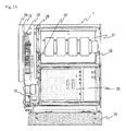
- FIG. 2B is a front view for describing an inner portion of a chassis of a power storage device according to an exemplary embodiment of the present invention (with battery containing bodies housed therein and a front door opened).
- FIG. 3A is a front-side perspective view for describing a structure of a chassis of a power storage device according to an exemplary embodiment of the present invention.
- FIG. 3B is a front view for describing a structure of a chassis of a power storage device according to an exemplary embodiment of the present invention (with no battery containing bodies housed therein and a front door opened).
- FIG. 3C is a perspective view of a battery containing body of a power storage device according to an exemplary embodiment of the present invention.
- FIG. 4 is a rear-side perspective view for describing a structure of a chassis of a power storage device according to an exemplary embodiment of the present invention.
- FIG. 5A is a perspective view for describing a battery containing body drop prevention structure in a power storage device according to an exemplary embodiment of the present invention.
- FIG. 5B is an enlarged partial perspective view for describing a battery containing body drop prevention structure in a power storage device according to an exemplary embodiment of the present invention.
- FIG. 5C is an enlarged partial side view for describing a battery containing body drop prevention structure of a power storage device according to an exemplary embodiment of the present invention.
- FIG. 5D is an enlarged partial perspective view for describing a battery containing body drop prevention structure in a power storage device according to an exemplary embodiment of the present invention.
- FIG. 6A is a perspective view for describing a battery containing body wrong insertion prevention structure in a power storage device according to an exemplary embodiment of the present invention.
- FIG. 6B is an enlarged partial perspective view for describing a battery containing body wrong insertion prevention structure (guide rail structure) in a power storage device according to an exemplary embodiment of the present invention.
- FIG. 6C is an enlarged partial perspective view for describing a battery containing body wrong insertion prevention structure in a power storage device according to an exemplary embodiment of the present invention.
- FIG. 6D is an enlarged partial side view for describing a battery containing body wrong insertion prevention structure in a power storage device according to an exemplary embodiment of the present invention.
- a power storage device including a plurality of battery containing bodies (for example, battery modules or battery packs), a power conditioner (hereinafter referred to as “PCS unit”), a battery management unit (hereinafter referred to as “BMU”) and a chassis that houses these can be provided, and a power storage system including the power storage device, and a control system unit (for example, a system controller) for controlling the power storage device can be also provided.
- a power storage device including a plurality of battery containing bodies (for example, battery modules or battery packs), a power conditioner (hereinafter referred to as “PCS unit”), a battery management unit (hereinafter referred to as “BMU”) and a chassis that houses these
- PCS unit power conditioner
- BMU battery management unit
- a chassis that houses these
- a power storage system including the power storage device, and a control system unit (for example, a system controller) for controlling the power storage device
- the power storage device and the power storage system can be connected, for example, between a commercial power supply provided in a general household and a load such as a home appliance for use as a backup power supply or supplementary power for the case of, e.g., a blackout, and furthermore, for use for supply of extra power to the commercial power source.
- a commercial power supply provided in a general household
- a load such as a home appliance for use as a backup power supply or supplementary power for the case of, e.g., a blackout
- supplementary power for the case of, e.g., a blackout
- the household dispersed power source can be connected to the power storage system.
- the BMU is provided between the respective battery containing bodies, and the PCS unit and the control system unit, and collects information on the states of the respective battery containing bodies and determines the states of the respective battery containing bodies based on the collected information. Also, the BMU outputs information indicating the states of the respective battery containing bodies to the PCS unit and the control system unit based on the results of the determination.
- the PCS unit converts alternate current supplied from an external power supply (e.g., a commercial power supply) to direct current and outputs the direct current to the respective battery containing bodies, and also converts direct current supplied from the respective battery containing bodies to alternate current and outputs the alternate current to the outside (a load).
- an external power supply e.g., a commercial power supply
- the control system unit mainly includes an arithmetic processor, a memory and a program stored in the memory, and comprehensively controls the power storage device.
- the control system unit for example, manages and controls information transmission between the BMU and the PCS unit, manages and controls the amounts of charge and discharge of the battery containing bodies, or switches between operation modes (a charge mode and a discharge mode) of the power storage device according to the program.
- the control system unit can be arranged outside of chassis 1 , separately from the power storage device, using a control device such as a personal computer. Also, the control system unit may be provided in the power storage device.
- the BMU is electrically connected to the battery containing bodies and the PCS unit (direct-current connection), and the PCS unit is electrically connected to the external power supply or the load (alternate-current connection).
- the control system unit is connected in such a manner that the control system unit can communicate with the BMU and the PCS unit.
- FIGS. 1A and 1B are a front-side perspective view and a rear-side perspective view illustrating an outer appearance of the chassis, respectively.
- FIGS. 2A and 2B are diagrams for describing the inside of the chassis: FIG. 2A is a side view with a side panel of the chassis removed; and FIG. 2B is a front view with front door 11 opened.
- FIGS. 3A and 4 are perspective views for describing a front-side structure and a rear-side structure of the chassis, respectively.
- a cuboidal housing case for example, a metal (for example, stainless steel) housing case having a cuboidal outer appearance, can be used.
- a surface that faces the installation surface such as the ground surface (horizontal surface) is a lower surface, and a surface on the upper side that faces the lower surface is an upper surface, and from among side surface portions forming a periphery of chassis 1 , a side surface portion including opening 20 is a front surface (front).
- a direction perpendicular to the installation surface is referred to as “height direction” or “upright or vertical” and a direction that is parallel to the ground surface and along a side surface is referred to as “transverse or horizontal” or “width direction”.
- chassis 1 has a flat cuboidal shape, and a front portion and a rear portion of chassis 1 each has a vertical rectangular shape, and opposite side surface portions of chassis 1 each have a horizontal rectangular shape.
- a size of chassis 1 can be set to, for example, 900 mm in height, 300 mm in width of the front surface (vertically-long side surface) (length parallel to the installation surface, of a side surface provided with front door 11 ) and 800 mm in width of the side surfaces (horizontally-long side faces) (length parallel to the installation surface, of surfaces extending from the front door 11 side to the maintenance door 12 side).
- Chassis 1 is provided with opening 20 in the vertically-long side surface (front surface), and is also provided with front door 11 (cover) for opening/closing the opening 20 .
- front door 11 can pivot about a pivot axis provided in the vicinity of an end portion of the door to open/close the opening (pivotable type), enabling enhancement in workability in installation, maintenance and inspection of the device.
- a detachable cover may be provided. A portion of contact between the door and the chassis is packed for keeping sufficient airtightness and water-tightness.
- each of battery containing bodies 21 can be inserted and removed through opening 20 .
- BMU 22 can be inserted and removed through opening 20 .
- battery containing bodies 21 and BMU 22 are housed in chassis 1 .
- Housed battery containing bodies 21 are supported by pivotable or detachable battery containing body cover 24 , and thereby fixed to prevent movement of battery containing bodies 21 in the removal direction due to, e.g., shaking.
- Battery containing body cover 24 can be fixed via, e.g., bolt or screw fastening.
- Battery containing bodies 21 each have a flat shape such as a flat cuboidal shape, and are arranged upright in parallel to one another so that respective end portions (vertically-long side surfaces) thereof face an opening face of opening 20 .
- a plurality of battery containing bodies 21 are housed in each of a lower-tier housing space and an upper-tier housing space, forming a two-tier arrangement. In the example illustrated in FIGS. 2B and 3A , a total of six battery containing bodies, three on the lower tier side and three on the upper tier side, are housed.
- Principal surfaces (surfaces along the insertion direction and the height direction) of adjacent battery containing bodies face one another, and these principal surfaces are arranged in parallel to the side surfaces (side surfaces along a direction from the front door side to the maintenance door side) of chassis 1 .
- Such arrangement of the flat shape battery containing bodies enables high-density housing.
- such parallel arrangement of the plurality of upright battery containing bodies 21 can avoid the effect of the weight of the adjacent battery containing bodies compared to a case where transversely-mounted battery containing bodies are stacked, enabling prevention of occurrence of a failure due to deflection or deformation.
- FIG. 3B is a front view of the chassis with no battery containing bodies 21 housed. At a back surface of the battery containing body housing section, chassis-side connectors 26 that receive respective rear-side connectors 37 of the battery containing bodies are provided.
- BMU 22 has a flat shape such as a flat cuboidal shape having a height that is similar to those of battery containing bodies 21 , and is adjacent to the battery containing body arranged at an end portion of the lower-tier side arrangement, and is disposed upright so that an end portion (vertically-long side face) of the BMU faces opening 20 .
- BMU 22 can be fixed via, e.g., bolt or screw fastening.
- cables connected to electronic devices such as PCS unit 23 disposed on the rear side of chassis 1 can be arranged and a control panel including, e.g., a break switch can be provided.
- Heat sink 14 is provided on an outer surface of PCS-provided door 13
- PCS unit 23 is provided on an inner surface (inner-wall surface) of PCS-provided door 13
- Heat insulating material 25 is provided at a position where heat insulating material 25 faces PCS unit 23 when the PCS-provided door 13 is closed.
- heat sink 14 is provided on the outer surface of door 13 provided at the rear surface portion and PCS unit 23 is provided on the inner surface in such a manner that heat sink 14 and PCS unit 23 face each other via door 13 , heat generated from PCS unit 23 can be released to the outside of the chassis by heat sink 14 .
- Heat sink 14 may be provided integrally with PCS-provided door 13 .
- PCS-provided door 13 with PCS unit 23 and heat sink 14 provided thereon is a pivotable one, and can open/close an opening on the upper side of the rear surface portion of the chassis body, thereby enhancing the workability in attachment or maintenance and inspection of PCS unit 23 and heat insulating material 25 .
- Heat insulating material 25 is provided between the PCS unit 23 , and housed battery containing body 21 and BMU 22 . Consequently, the effect of heat generation by PCS unit 23 on battery containing bodies 21 and BMU 22 can be suppressed. A portion of contact between door 13 and chassis 1 is packed to keep sufficient airtightness and water-tightness.
- Maintenance door 12 is a pivotable one, and can open/close an opening on the lower side of the rear surface portion of the chassis body, and inside the opening, fused switches, breakers or the like are arranged. Maintenance door 12 protects the switches, the breakers or the like from the external environment, and can easily be opened/closed, enhancing the workability in maintenance. A portion of contact between maintenance door 12 and chassis 1 is packed to keep sufficient airtightness and water-tightness.
- chassis 1 can be installed on mount 10 and fixed via, e.g., bolts.
- the installation of chassis 1 on mount 10 can enhance the stability and prevent chassis 1 from falling, and can also prevent water exposure due to a puddle of rain water.
- a sunshade covering the upper surface of chassis 1 can be provided.
- FIG. 3C is a perspective view of battery containing body 21 as placed upright.
- reference numeral 31 denotes a handle
- reference numeral 32 denotes a front-side connector
- reference numeral 33 denotes a projection portion for guide rail fitting
- reference numeral 34 denotes a recess portion (support portion)
- reference numeral 37 denotes a rear-side connector.
- placed upright refers to a state in which battery containing body 21 is placed with a surface other than two principal surfaces having a largest area, as a bottom.
- an outer appearance of battery containing body 21 can have a flat shape such as a flat cuboidal shape in which lengths in a longitudinal direction (insertion direction) of a lower end portion and an upper end portion of battery containing body 21 placed upright are longer than a length in a longitudinal direction (vertical direction) of an end portion on the front side in the insertion direction of battery containing body 21 .
- Handle 31 is provided at the end portion on the front side in the direction of insertion to chassis 1 . By holding handle 31 , battery containing body 21 can easily be inserted to and removed from the power storage device.
- connector 32 is provided at the end portion provided with handle 31 .
- the end portion faces the opening of chassis 1 when battery containing body 21 is housed in chassis 1 , enabling attachment/detachment of a cable to/from connector 32 after insertion of battery containing body 21 .
- a rear-side connector 37 is provided at an end portion on the opposite side of the end portion provided with handle 31 (back side in the insertion direction) of the battery containing body.
- Battery containing body 21 is provided with recess portion 34 at least at a lower end portion thereof.
- recess portion 34 functions as a support portion for supporting battery containing body 21 with one hand (in this case, the other hand can hold handle 31 ).
- the hand holding recess portion 34 is put in the recess portion, enabling prevention of slippage of the hand in the insertion/removal direction and thus facilitating the insertion/removal work.
- recess portion 34 can be held, making it easy to hold the end portion provided with recess portion 34 , and thus enabling prevention of drop of battery containing body 21 and enabling battery containing body 21 to be carried around easily.
- recess portion 34 is provided at each of the lower end portion and the upper end portion of battery containing body 21 , resulting in an increase in holding position, which decreases the necessity to change the position of the battery containing body or a standing position when holding the battery containing body up, enhancing the workability.
- Each recess portion 34 is formed to have a size that can receive the fingers other than the thumb or the palm of a hand, making it easier to hold and enhancing the ease of holding.
- Each recess portion 34 is preferably provided on the back side relative to a center portion in the insertion direction.
- the weight imposed on the other hand that holds recess portion 34 can be reduced compared to cases where the front side portion of the lower end portion is held. Also, the balance of the battery containing body is improved, whereby the battery containing body can easily be held up.
- projection portions 33 that fit in respective guide rails in chassis 1 are provided.
- a first lower end portion-side projection portion extending in the insertion direction, and a second lower end portion-side projection portion extending in the insertion direction, which is provided apart from the first lower end portion-side projection portion can be provided.
- Recess portion 34 provided at the lower end portion of the battery containing body 21 can be formed by a space between the first lower end portion-side projection portion and the second lower end portion-side projection portion.
- a first upper end portion-side projection portion extending in the insertion direction and a second upper end portion-side projection portion extending in the insertion direction, which is provided apart from the first upper end portion-side projection portion, can be provided.
- Recess portion 34 provided at the upper end portion of the battery containing body 21 can be formed by a space between the first upper end portion-side projection portion and the second upper end portion-side projection portion.
- Each battery containing body (for example, battery module) includes a plurality of secondary batteries in a case having a flat shape such as a flat cuboidal shape. At an inner surface of each of two principal surfaces of the case, a plurality of recess portions are provided, and the batteries can be arranged one by one in these recess portions. For example, a battery containing body that holds a total of eight batteries can be obtained by arranging four batteries on one principal surface and arranging four batteries on the other principal surface.
- the plurality of batteries in the case can be connected in series.
- This case can be provided with handle 31 and projection portions 33 by integral molding.
- the arrangement, the number and the connection method of the plurality of batteries are not limited to the ones described above, and can arbitrarily be determined according to desired design specifications.
- film package batteries can be used.
- Each film package battery contains battery elements formed by alternately stacking positive electrodes and negative electrodes via separators, and the battery elements and an electrolyte solution are encapsulated in a container formed of a packaging film such as a laminate film. From the perspective of high-density housing in the case, it is desirable to use batteries having a flat cuboidal shape. For such batteries, lithium ion batteries are favorably used.
- these battery containing bodies are arranged upright in parallel to one another in chassis 1 .
- Each battery containing body is inserted with the end portion side provided with handle 31 as the front, and the end portion provided with the handle faces opening 20 (or the inner surface of closed front door 11 ) of the chassis.
- FIG. 3A the plurality of battery containing bodies 21 are illustrated in an integrated manner; however, the respective battery containing bodies are independent from one another and each can solely be transferred to/from chassis 1 .
- Battery containing bodies 21 housed in chassis 1 are connected in series, and adjacent battery containing bodies 21 are connected via a cable connecting front-side connectors 32 .
- Each of opposite ends of the battery containing bodies connected in series is connected to BMU 22 via the cable connected to the front-side connector 32 .
- Rear-side connectors 37 can be electrically connected to the BMU, whereby information indicating the states of the respective battery containing bodies is input to the BMU.
- a reinforcement material may be attached to the outer side of chassis 1 as necessary.
- the outer side of chassis 1 can be covered by exterior panels.
- side panels covering opposite side surfaces and an upper panel covering the upper surface can be provided.
- the respective panels may be mutually fixed via rivets or welding or fixed to the chassis as necessary.
- Each panel can be formed using a member of a metal such as stainless steel.
- the present exemplary embodiment having the structure described below enables prevention of drop of a heavy (for example, 9 kg) battery containing body in the work for transferring the battery containing body in and out, and further enables prevention of wrong insertion of the battery containing body, consequently enabling enhancement in work efficiency. Furthermore, the efficiency of battery containing body connection work can be enhanced and the connection structure can be simplified (for example, the cable can be shortened).
- FIGS. 5A to 5D are diagrams for describing a drop prevention structure for work for removal of a battery containing body
- FIGS. 6A to 6D are diagrams for describing a wrong insertion prevention structure for work for inserting a battery containing body.
- the battery containing body in each Figure is illustrated with the side surface (principal surface) on the front side of the battery containing body case and the contents (e.g. batteries) omitted to clearly show a hollow shape of the battery containing body case.
- a lower-side end portion (first end portion) of upright battery containing body 21 housed in chassis 1 is fitted in lower-side guide rail 51 , and an upper-side end portion (second end portion) of the same is fitted in upper-side guide rail 52 , and thereby battery containing body 21 can be inserted to and removed from the chassis 1 along these guide rails.
- FIG. 5A when battery containing body 21 is pulled out in the direction of the arrow in the Figure from a state in which the battery containing body is inserted, as illustrated in the enlarged views of FIGS.
- protrusion portion (first protrusion portion) 35 provided in the vicinity of a corner portion on the back side in the insertion direction of the lower-side end portion (first end portion) of battery containing body 21 catches on stopper 54 provided at a terminal portion on the front side in the battery containing body insertion direction (the opening 20 side of chassis 1 ) of lower-side guide rail 51 and thereby is prevented from being pulled out any further in the arrow direction.
- the vicinity of the corner portion on the back side in the insertion direction means a region of less than 50% of the total length in the insertion direction of the lower-side end portion (or the upper-side end portion) of the battery containing body from the corner on the back side in the insertion direction (or a site in the region), more specifically a region of 30% or less, still more specifically 20% or less of the total length in the insertion direction from the corner in the back side in the insertion direction (or a site in the region).
- stopper 54 and receiving portion 53 can be integrally formed using a same member.
- Stopper 54 is a plate-like portion having a planar surface crossing the insertion direction of battery containing body 21 (longitudinal direction of guide rail 51 ) (preferably at right angles) and extending along the height direction (direction perpendicular to the power storage device installation surface). Stopper 54 formed of this plate-like portion is disposed on at least one side of a pathway which is an extension in the removal direction (in the direction of the arrow in the Figure) of a pathway for insertion and removal of the battery containing body lower-side end portion along lower-side guide rail 51 . As illustrated in FIG.
- stopper 54 is disposed on at least one side of the extension pathway so that stopper 54 is positioned on a side surface of projection portion 33 . More specifically, as illustrated in FIGS.
- a recess portion in which the lower-side end portion (projection portion 33 ) of battery containing body 21 is to be fitted is provided in the plate-like portion, which is stopper 54 , and the portion around the recess portion of the plate-like portion engages with protrusion portion 35 provided on one side of the lower-side end portion (projection portion 33 ) of the battery containing body (i.e., catches on the protrusion portion) and functions as a stopper.
- Protrusion portion 35 provided at battery containing body 21 protrudes in a width direction of the lower-side end portion (or projection portion 33 ) of battery containing body 21 (that is, on the one side where stopper 54 is provided as viewed in the insertion direction) and engages with stopper (plate-like portion) 54 (i.e., catches on the stopper) when removing battery containing body 21 .
- Protrusion portion 35 does not come into contact with guide rail 51 when inserting battery containing body 21 . While as illustrated in FIGS. 5B and 5D , protrusion portion 35 protrudes on the side plate (lower side plate 51 a ) side of lower-side guide rail 51 , as illustrated in FIG. 5C , a height of the side plate is reduced to prevent protrusion portion 35 and the side plate (lower side plate 51 a ) from coming into contact with each other when inserting the battery containing body.
- size Hp in the height direction of protrusion portion 35 is set so that a part of contact with stopper 54 has a contact region that provides sufficient engagement.
- size Hp is set not to prevent the lower-side end portion (or projection portions 33 ) of battery containing body 21 from being fitted in the lower-side guide rail. If a position of a lower end of protrusion portion 35 is too close to the lower-side end portion (bottom position) of the battery containing body (that is, too close to the bottom position of lower-side guide rail 51 ), it is necessary to reduce height Hs of the side plate (lower side plate 51 a ) accordingly, resulting in insufficiency in height of the side plate, which makes battery containing body 21 easily come off from lower-side guide rail 51 when inserting battery containing body 21 .
- protrusion portion 35 is a protrusion portion from a side surface of the projection portion.
- size Hp in the height direction of protrusion portion 35 is set to be smaller than height Hc of projection portion 33 .
- An end portion on the front side in the insertion direction of upper-side guide rail 52 is located at a position withdrawn to the back side relative to an end portion on the front side in the insertion direction of lower-side guide rail 51 .
- the length of the withdrawal is preferably not less than a length from a position of contact between protrusion portion 35 and stopper 54 to the back-side corner portion of the lower-side end portion of the battery containing body.
- the vicinity of the back-side corner portion of the lower-side end portion of battery containing body 21 is provided with a tapered shape in which the bottom surface is inclined (gradually spaced from the ground surface) toward the back-side corner portion, enabling facilitation of the raise with the back-side corner portion as a support.
- the structure according to the present exemplary embodiment prevents battery containing body 21 from being inserted any further from the state illustrated in FIGS. 6A, 6C and 6D .
- second protrusion portion 36 provided in the vicinity of a corner portion on the back side in the insertion direction of the second end portion of battery containing body 21 , and a guide plate (higher guide plate 51 b ) of lower-side guide rail 51 come into contact with each other, which prevents battery containing body 21 from being inserted any further in the direction of the arrow in the Figures.
- This failure to insert the battery containing body makes it easy to notice the wrong insertion.
- second protrusion portion 36 catches on stopper 54 and is prevented from being pulled out any further.
- the vicinity of the corner portion on the back side in the insertion direction of the second end portion of battery containing body 21 (part on the back side from second protrusion portion 36 ) is supported by receiving portion 53 . Consequently, battery containing body 21 is prevented from being dropped when pulling out battery containing body 21 .
- Such drop prevention structure for pull-out is similar to the above-described drop prevention structure provided by engagement between first protrusion portion 35 and stopper 54 .
- Second protrusion portion 36 has a structure that is similar to the drop prevention structure of first protrusion portion 35 . Also, a size in the height direction of second protrusion portion 36 is set so that a part of contact with higher side plate 51 b has a contact region that provides sufficient engagement. As illustrated in FIG. 3C , if projection portion 33 for guide rail fitting is provided at the second end portion (and the first end portion) of the battery containing body, second protrusion portion 36 is a protrusion portion from a side surface of the projection portion. Here, a size in the height direction of second protrusion portion 36 is set to be smaller than a height of projection portion 33 .
- Second protrusion portion 36 described above is provided on the side that is the same as first protrusion portion 35 as viewed in the insertion direction of the battery containing body.
- lower-side guide rail 51 includes a pair of side plates 51 a and 51 b that face each other and extend in the insertion direction, the side plates 51 a and 51 b being capable of supporting the first and second end portions of the battery containing body.
- upper-side guide rail 52 also includes a pair of side plates.
- each guide rail can include plural pairs of side plates aligned along the insertion direction.
- Each guide rail can include a pair of side plates each continuously extending over the entirety in the extending direction (insertion direction) of the guide rail.
- one side plate (higher side plate 51 b ) is higher than the other side plate (lower side plate 51 b ).
- higher side plate 51 b is positioned on the side opposite to first protrusion portion 35 as viewed in the insertion direction. Therefore, the first protrusion portion does not engage with the higher side plate.
- lower side plate 51 a is located on the side that is the same as the first protrusion portion, lower side plate 51 a is formed to be low enough to avoid engagement with the first protrusion portion, and thus the first protrusion portion does not engage with the lower side plate, either. Consequently, the first end portion of the battery containing body can be fitted in lower-side guide rail 51 and insertion of the battery containing body is not blocked.
- the second end portion of battery containing body 21 is fitted in upper-side guide rail 52 , and second protrusion portion 36 and one side plate (on the same side) of upper-side guide rail 52 , which are located on the same side as viewed in the insertion direction, are set to have respective sizes that avoid engagement therebetween.
- higher side plate 51 b is positioned on the side that is the same as second protrusion portion 36 as viewed in the insertion direction. Therefore, the second protrusion portion engages with the higher side plate (bumps into the higher side plate), whereby insertion of the battery containing body is blocked.
- Upper-side guide rail 52 in this case can have a normal structure if upper-side guide rail 52 can engage with the second end portion; also, one side plate of upper-side guide rail 52 may be made larger in the height direction so as to engage with first protrusion portion 35 .
- the side plate of upper-side guide rail 52 that engages with first protrusion portion 35 is disposed on the side that is the same as higher guide plate 51 b of lower-side guide rail 51 as viewed in the insertion direction. Consequently, insertion of the battery containing body can be blocked by both the upper-side guide rail and the lower-side guide rail.
- front-side connector 32 is provided at an end portion of each battery containing body 21 , and front-side connectors 32 is disposed on the upper side or the lower side relative to a center in the height direction of the end portion of the battery containing body (for example, handle 31 ). Furthermore, as illustrated in FIG. 3A , battery containing bodies 21 are housed in such a manner that front-side connector 32 are arranged in parallel on the upper side or the lower side relative to handles 31 . Also, as illustrated in FIG.
- Such arrangement that makes the connectors close to one another enables reduction in length of the cable interconnecting the connectors and thus enables enhancement in efficiency of work for connecting/disconnecting connectors.
- the vertical positions of the battery containing bodies at the time of insertion are determined, and thus, it is necessary to prevent wrong insertion of an upside-down battery containing body.
- chassis-side connectors 26 are provided at the respective rear-side end portions of battery containing bodies 21 , and are directly connected to chassis-side connectors 26 provided in chassis 1 when battery containing bodies 21 are inserted.
- Such connection structure requires no cable and enables connection/disconnection between the connectors accompanying insertion/removal of battery containing body 21 , enabling enhancement in work efficiency.
- chassis-side connectors 26 form an particular arrangement as with front-side connectors 32 described above. In other words, the chassis-side connectors are arranged in parallel on the upper side or the lower side relative to a center in the height direction of the battery containing body housing section and rear-side connectors 37 of battery containing bodies 21 as housed are also arranged so as to correspond to such arrangement.
- chassis-side connectors 26 in the first housing section are arranged in parallel on the upper side relative to the center in the height direction of the first housing section
- chassis-side connectors 26 in the second housing section are arranged in parallel on the lower side relative to the center in the height direction of the second housing section
- rear-side connectors 37 of the battery containing bodies as housed are also arranged so as to correspond to such arrangement.
- the above-described connector connection structure enables substantial improvement in efficiency of installation work and maintenance and inspection work for the power storage device, jointly with the above-described wrong insertion prevention and drop prevention structures.
Landscapes
- Chemical & Material Sciences (AREA)
- Chemical Kinetics & Catalysis (AREA)
- Electrochemistry (AREA)
- General Chemical & Material Sciences (AREA)
- Engineering & Computer Science (AREA)
- Manufacturing & Machinery (AREA)
- Microelectronics & Electronic Packaging (AREA)
- Battery Mounting, Suspending (AREA)
Abstract
Description
- Patent Literature 1: JP2010-182541A
- Patent Literature 2: JP2012-9309A
- 1 chassis
- 10 mount
- 11 front door (cover)
- 12 maintenance door
- 13 PCS-provided door
- 14 heat sink
- 20 opening
- 21 battery containing body
- 22 BMU
- 23 PCS unit
- 24 battery containing body cover
- 25 heat insulating material
- 26 chassis-side connector
- 31 handle
- 32 front-side connector of battery containing body
- 33 projection portion for guide rail fitting
- 34 recess portion (support portion)
- 35 protrusion portion (first protrusion portion)
- 36 protrusion portion (second protrusion portion)
- 37 rear-side connector of battery containing body
- 51 lower-side guide rail
- 51 a lower side plate
- 51 b higher side plate
- 52 upper-side guide rail
- 53 receiving portion
- 54 stopper
Claims (20)
Applications Claiming Priority (3)
| Application Number | Priority Date | Filing Date | Title |
|---|---|---|---|
| JP2012060702 | 2012-03-16 | ||
| JP2012-060702 | 2012-03-16 | ||
| PCT/JP2013/057442 WO2013137446A1 (en) | 2012-03-16 | 2013-03-15 | Power-storage device |
Publications (2)
| Publication Number | Publication Date |
|---|---|
| US20150044512A1 US20150044512A1 (en) | 2015-02-12 |
| US9564620B2 true US9564620B2 (en) | 2017-02-07 |
Family
ID=49161341
Family Applications (1)
| Application Number | Title | Priority Date | Filing Date |
|---|---|---|---|
| US14/383,132 Active 2034-01-02 US9564620B2 (en) | 2012-03-16 | 2013-03-15 | Power storage device |
Country Status (5)
| Country | Link |
|---|---|
| US (1) | US9564620B2 (en) |
| EP (1) | EP2827402A4 (en) |
| JP (2) | JP6146820B2 (en) |
| CN (1) | CN104170119B (en) |
| WO (1) | WO2013137446A1 (en) |
Cited By (3)
| Publication number | Priority date | Publication date | Assignee | Title |
|---|---|---|---|---|
| USD842239S1 (en) * | 2014-02-12 | 2019-03-05 | Abb Technology Ag | Charging station |
| US10875506B2 (en) * | 2017-03-23 | 2020-12-29 | Honda Motor Co., Ltd. | Housing device |
| US11189875B1 (en) * | 2016-12-09 | 2021-11-30 | Green Cubes Technology, Llc | Battery systems containing recyclable battery portions |
Families Citing this family (6)
| Publication number | Priority date | Publication date | Assignee | Title |
|---|---|---|---|---|
| WO2015151884A1 (en) * | 2014-03-31 | 2015-10-08 | 日本電気株式会社 | Rechargeable-battery device |
| JP7381285B2 (en) * | 2019-10-15 | 2023-11-15 | ファナック株式会社 | Auxiliary power equipment and industrial machinery |
| WO2022067427A1 (en) * | 2020-10-02 | 2022-04-07 | Blue Solutions Canada Inc. | Energy storage unit having a rack assembly and a plurality of battery modules |
| KR20220080516A (en) * | 2020-12-07 | 2022-06-14 | 주식회사 엘지에너지솔루션 | A board type ESS battery pack |
| JP7533247B2 (en) * | 2021-01-28 | 2024-08-14 | トヨタ自動車株式会社 | Power storage device |
| US20220306231A1 (en) * | 2021-03-25 | 2022-09-29 | Shimano Inc. | Operating device for human-powered vehicle |
Citations (19)
| Publication number | Priority date | Publication date | Assignee | Title |
|---|---|---|---|---|
| JPS59129166U (en) | 1983-02-19 | 1984-08-30 | 古河電池株式会社 | Storage battery storage device |
| JPS6027024U (en) | 1983-08-02 | 1985-02-23 | 川崎重工業株式会社 | Locking mechanism for the inner tray in the box |
| JPH0459064U (en) | 1990-09-28 | 1992-05-20 | ||
| US5140138A (en) * | 1989-05-16 | 1992-08-18 | Kabushiki Kaisha Toshiba | Battery operated personal terminal apparatus |
| JPH11115504A (en) | 1997-10-21 | 1999-04-27 | Fuji Heavy Ind Ltd | Battery mounting structure for automobile |
| JP3079998U (en) | 2000-12-14 | 2001-09-07 | 飛瑞股▲分▼有限公司 | Uninterruptible power system |
| JP2002057470A (en) | 2000-08-09 | 2002-02-22 | Fujitsu Denso Ltd | Heavy article mounting device for cabinet |
| JP2004231024A (en) | 2003-01-30 | 2004-08-19 | Kawasaki Heavy Ind Ltd | Battery box for railroad vehicle |
| US20060056142A1 (en) | 2004-09-10 | 2006-03-16 | Fumikazu Takahashi | Data processing unit and DC backup power supply |
| US20060093899A1 (en) * | 2004-10-28 | 2006-05-04 | Yoon-Cheol Jeon | Battery module |
| JP2006185823A (en) | 2004-12-28 | 2006-07-13 | Sony Corp | Battery |
| US20070037044A1 (en) * | 2005-08-12 | 2007-02-15 | Sony Corporation | Secondary battery |
| JP2010182541A (en) | 2009-02-05 | 2010-08-19 | Sanyo Electric Co Ltd | Charge accumulation device |
| WO2010149243A1 (en) | 2009-06-23 | 2010-12-29 | Bayerische Motoren Werke Aktiengesellschaft | Device for supplying voltage to a motor vehicle, comprising a cooler block |
| JP2011000913A (en) | 2009-06-16 | 2011-01-06 | Toyota Motor Corp | Mounting structure for energy storage |
| WO2011086771A1 (en) | 2010-01-15 | 2011-07-21 | 三菱自動車工業株式会社 | Battery case for vehicle |
| JP2012009309A (en) | 2010-06-25 | 2012-01-12 | Sanyo Electric Co Ltd | Storage system of electricity |
| JP2012009310A (en) | 2010-06-25 | 2012-01-12 | Sanyo Electric Co Ltd | Storage system of electricity |
| JP2012009311A (en) | 2010-06-25 | 2012-01-12 | Sanyo Electric Co Ltd | Storage system of electricity |
-
2013
- 2013-03-15 CN CN201380014708.6A patent/CN104170119B/en active Active
- 2013-03-15 US US14/383,132 patent/US9564620B2/en active Active
- 2013-03-15 WO PCT/JP2013/057442 patent/WO2013137446A1/en active Application Filing
- 2013-03-15 JP JP2014505028A patent/JP6146820B2/en active Active
- 2013-03-15 EP EP13761927.6A patent/EP2827402A4/en not_active Withdrawn
-
2014
- 2014-02-14 JP JP2014026028A patent/JP5744257B2/en active Active
Patent Citations (23)
| Publication number | Priority date | Publication date | Assignee | Title |
|---|---|---|---|---|
| JPS59129166U (en) | 1983-02-19 | 1984-08-30 | 古河電池株式会社 | Storage battery storage device |
| JPS6027024U (en) | 1983-08-02 | 1985-02-23 | 川崎重工業株式会社 | Locking mechanism for the inner tray in the box |
| US5140138A (en) * | 1989-05-16 | 1992-08-18 | Kabushiki Kaisha Toshiba | Battery operated personal terminal apparatus |
| JPH0459064U (en) | 1990-09-28 | 1992-05-20 | ||
| JPH11115504A (en) | 1997-10-21 | 1999-04-27 | Fuji Heavy Ind Ltd | Battery mounting structure for automobile |
| JP2002057470A (en) | 2000-08-09 | 2002-02-22 | Fujitsu Denso Ltd | Heavy article mounting device for cabinet |
| JP3079998U (en) | 2000-12-14 | 2001-09-07 | 飛瑞股▲分▼有限公司 | Uninterruptible power system |
| JP2004231024A (en) | 2003-01-30 | 2004-08-19 | Kawasaki Heavy Ind Ltd | Battery box for railroad vehicle |
| US20060056142A1 (en) | 2004-09-10 | 2006-03-16 | Fumikazu Takahashi | Data processing unit and DC backup power supply |
| JP2006079751A (en) | 2004-09-10 | 2006-03-23 | Hitachi Computer Peripherals Co Ltd | Information processing apparatus and dc backup power source apparatus |
| US20060093899A1 (en) * | 2004-10-28 | 2006-05-04 | Yoon-Cheol Jeon | Battery module |
| JP2006185823A (en) | 2004-12-28 | 2006-07-13 | Sony Corp | Battery |
| US20070037044A1 (en) * | 2005-08-12 | 2007-02-15 | Sony Corporation | Secondary battery |
| JP2010182541A (en) | 2009-02-05 | 2010-08-19 | Sanyo Electric Co Ltd | Charge accumulation device |
| JP2011000913A (en) | 2009-06-16 | 2011-01-06 | Toyota Motor Corp | Mounting structure for energy storage |
| WO2010149243A1 (en) | 2009-06-23 | 2010-12-29 | Bayerische Motoren Werke Aktiengesellschaft | Device for supplying voltage to a motor vehicle, comprising a cooler block |
| DE102009030017A1 (en) | 2009-06-23 | 2010-12-30 | Bayerische Motoren Werke Aktiengesellschaft | Device for supplying power to a motor vehicle with a radiator block |
| US20120129018A1 (en) | 2009-06-23 | 2012-05-24 | Bayerische Motoren Werke Aktiengesellschaft | Device That is Intended for Supplying Power to a Motor Vehicle and Comprises a Cooler Block |
| WO2011086771A1 (en) | 2010-01-15 | 2011-07-21 | 三菱自動車工業株式会社 | Battery case for vehicle |
| US20120164500A1 (en) | 2010-01-15 | 2012-06-28 | Mitsubishi Jidosha Kogyo Kabushiki Kaisha | Automotive battery case |
| JP2012009309A (en) | 2010-06-25 | 2012-01-12 | Sanyo Electric Co Ltd | Storage system of electricity |
| JP2012009310A (en) | 2010-06-25 | 2012-01-12 | Sanyo Electric Co Ltd | Storage system of electricity |
| JP2012009311A (en) | 2010-06-25 | 2012-01-12 | Sanyo Electric Co Ltd | Storage system of electricity |
Non-Patent Citations (4)
| Title |
|---|
| Chinese Office Action corresponding to Chinese Application No. 201380014708.6, dated Nov. 30, 2015, 11 pages. |
| Extended European Search Report corresponding to European Application No. 13761927.6, dated Jul. 23, 2015, 4 pages. |
| International Search Report corresponding to PCT/JP2013/057442, dated May 7, 2013 (5 pages). |
| Japanese Office Action with partial English translation corresponding to Japanese Patent Application No. 2014-026028, dated Jan. 6, 2015, 5 pages. |
Cited By (3)
| Publication number | Priority date | Publication date | Assignee | Title |
|---|---|---|---|---|
| USD842239S1 (en) * | 2014-02-12 | 2019-03-05 | Abb Technology Ag | Charging station |
| US11189875B1 (en) * | 2016-12-09 | 2021-11-30 | Green Cubes Technology, Llc | Battery systems containing recyclable battery portions |
| US10875506B2 (en) * | 2017-03-23 | 2020-12-29 | Honda Motor Co., Ltd. | Housing device |
Also Published As
| Publication number | Publication date |
|---|---|
| EP2827402A4 (en) | 2015-08-26 |
| JPWO2013137446A1 (en) | 2015-08-03 |
| JP2015008120A (en) | 2015-01-15 |
| WO2013137446A1 (en) | 2013-09-19 |
| US20150044512A1 (en) | 2015-02-12 |
| CN104170119A (en) | 2014-11-26 |
| JP5744257B2 (en) | 2015-07-08 |
| EP2827402A1 (en) | 2015-01-21 |
| CN104170119B (en) | 2016-10-12 |
| JP6146820B2 (en) | 2017-06-14 |
Similar Documents
| Publication | Publication Date | Title |
|---|---|---|
| US9564620B2 (en) | Power storage device | |
| US10056586B2 (en) | Battery containing body and power storage device | |
| US9502738B2 (en) | Power storage device | |
| EP2693514B1 (en) | Rack type power device and battery pack with detachable connector | |
| CN103493241B (en) | Battery case, the sub-battery case being used in battery case and use their set of cells | |
| US8558507B2 (en) | Secondary battery storage system rack with fire extinguisher device | |
| US8704486B2 (en) | Electricity storage system | |
| JP6102541B2 (en) | Storage device and storage battery replacement method | |
| KR101557415B1 (en) | portable apparatus for electric charging and discharging | |
| JP5936114B2 (en) | Power storage device | |
| US20220285779A1 (en) | Battery rack having fixing frame and energy storage system | |
| JP6323006B2 (en) | Power storage device | |
| KR101413831B1 (en) | A Battery Cartridge | |
| JP2020515003A (en) | Battery pack fixing device | |
| KR101545237B1 (en) | Battery pack module of enlarged capacity type |
Legal Events
| Date | Code | Title | Description |
|---|---|---|---|
| AS | Assignment |
Owner name: NEC ENERGY DEVICES, LTD., JAPAN Free format text: ASSIGNMENT OF ASSIGNORS INTEREST;ASSIGNORS:KAWAGUCHI, DAISUKE;IIDA, AKIRA;SUZUKI, TORU;REEL/FRAME:033674/0259 Effective date: 20140821 Owner name: NEC ENGINEERING, LTD., JAPAN Free format text: ASSIGNMENT OF ASSIGNORS INTEREST;ASSIGNORS:KAWAGUCHI, DAISUKE;IIDA, AKIRA;SUZUKI, TORU;REEL/FRAME:033674/0259 Effective date: 20140821 Owner name: NEC CORPORATION, JAPAN Free format text: ASSIGNMENT OF ASSIGNORS INTEREST;ASSIGNORS:KAWAGUCHI, DAISUKE;IIDA, AKIRA;SUZUKI, TORU;REEL/FRAME:033674/0259 Effective date: 20140821 |
|
| STCF | Information on status: patent grant |
Free format text: PATENTED CASE |
|
| AS | Assignment |
Owner name: NEC PLATFORMS, LTD., JAPAN Free format text: MERGER;ASSIGNOR:NEC ENGINEERING, LTD.;REEL/FRAME:043590/0213 Effective date: 20170401 |
|
| AS | Assignment |
Owner name: ENVISION AESC ENERGY DEVICES LTD., JAPAN Free format text: CHANGE OF NAME;ASSIGNOR:NEC ENERGY DEVICES LTD.;REEL/FRAME:050844/0246 Effective date: 20190329 |
|
| MAFP | Maintenance fee payment |
Free format text: PAYMENT OF MAINTENANCE FEE, 4TH YEAR, LARGE ENTITY (ORIGINAL EVENT CODE: M1551); ENTITY STATUS OF PATENT OWNER: LARGE ENTITY Year of fee payment: 4 |
|
| MAFP | Maintenance fee payment |
Free format text: PAYMENT OF MAINTENANCE FEE, 8TH YEAR, LARGE ENTITY (ORIGINAL EVENT CODE: M1552); ENTITY STATUS OF PATENT OWNER: LARGE ENTITY Year of fee payment: 8 |