US9562968B2 - Sensor system and method for determining target location using sparsity-based processing - Google Patents
Sensor system and method for determining target location using sparsity-based processing Download PDFInfo
- Publication number
- US9562968B2 US9562968B2 US14/060,001 US201314060001A US9562968B2 US 9562968 B2 US9562968 B2 US 9562968B2 US 201314060001 A US201314060001 A US 201314060001A US 9562968 B2 US9562968 B2 US 9562968B2
- Authority
- US
- United States
- Prior art keywords
- signal
- est
- target
- location
- vector
- Prior art date
- Legal status (The legal status is an assumption and is not a legal conclusion. Google has not performed a legal analysis and makes no representation as to the accuracy of the status listed.)
- Expired - Fee Related, expires
Links
Images
Classifications
-
- G—PHYSICS
- G01—MEASURING; TESTING
- G01S—RADIO DIRECTION-FINDING; RADIO NAVIGATION; DETERMINING DISTANCE OR VELOCITY BY USE OF RADIO WAVES; LOCATING OR PRESENCE-DETECTING BY USE OF THE REFLECTION OR RERADIATION OF RADIO WAVES; ANALOGOUS ARRANGEMENTS USING OTHER WAVES
- G01S13/00—Systems using the reflection or reradiation of radio waves, e.g. radar systems; Analogous systems using reflection or reradiation of waves whose nature or wavelength is irrelevant or unspecified
- G01S13/66—Radar-tracking systems; Analogous systems
- G01S13/72—Radar-tracking systems; Analogous systems for two-dimensional [2D] tracking, e.g. combination of angle and range tracking, track-while-scan radar
- G01S13/723—Radar-tracking systems; Analogous systems for two-dimensional [2D] tracking, e.g. combination of angle and range tracking, track-while-scan radar by using numerical data
- G01S13/726—Multiple target tracking
-
- G—PHYSICS
- G01—MEASURING; TESTING
- G01S—RADIO DIRECTION-FINDING; RADIO NAVIGATION; DETERMINING DISTANCE OR VELOCITY BY USE OF RADIO WAVES; LOCATING OR PRESENCE-DETECTING BY USE OF THE REFLECTION OR RERADIATION OF RADIO WAVES; ANALOGOUS ARRANGEMENTS USING OTHER WAVES
- G01S13/00—Systems using the reflection or reradiation of radio waves, e.g. radar systems; Analogous systems using reflection or reradiation of waves whose nature or wavelength is irrelevant or unspecified
- G01S13/02—Systems using reflection of radio waves, e.g. primary radar systems; Analogous systems
- G01S13/06—Systems determining position data of a target
- G01S13/08—Systems for measuring distance only
- G01S13/10—Systems for measuring distance only using transmission of interrupted, pulse modulated waves
- G01S13/18—Systems for measuring distance only using transmission of interrupted, pulse modulated waves wherein range gates are used
-
- G—PHYSICS
- G01—MEASURING; TESTING
- G01S—RADIO DIRECTION-FINDING; RADIO NAVIGATION; DETERMINING DISTANCE OR VELOCITY BY USE OF RADIO WAVES; LOCATING OR PRESENCE-DETECTING BY USE OF THE REFLECTION OR RERADIATION OF RADIO WAVES; ANALOGOUS ARRANGEMENTS USING OTHER WAVES
- G01S13/00—Systems using the reflection or reradiation of radio waves, e.g. radar systems; Analogous systems using reflection or reradiation of waves whose nature or wavelength is irrelevant or unspecified
- G01S13/02—Systems using reflection of radio waves, e.g. primary radar systems; Analogous systems
- G01S13/50—Systems of measurement based on relative movement of target
- G01S13/52—Discriminating between fixed and moving objects or between objects moving at different speeds
- G01S13/522—Discriminating between fixed and moving objects or between objects moving at different speeds using transmissions of interrupted pulse modulated waves
- G01S13/524—Discriminating between fixed and moving objects or between objects moving at different speeds using transmissions of interrupted pulse modulated waves based upon the phase or frequency shift resulting from movement of objects, with reference to the transmitted signals, e.g. coherent MTi
-
- G—PHYSICS
- G01—MEASURING; TESTING
- G01S—RADIO DIRECTION-FINDING; RADIO NAVIGATION; DETERMINING DISTANCE OR VELOCITY BY USE OF RADIO WAVES; LOCATING OR PRESENCE-DETECTING BY USE OF THE REFLECTION OR RERADIATION OF RADIO WAVES; ANALOGOUS ARRANGEMENTS USING OTHER WAVES
- G01S3/00—Direction-finders for determining the direction from which infrasonic, sonic, ultrasonic or electromagnetic waves, or particle emission, not having a directional significance, are being received
- G01S3/02—Direction-finders for determining the direction from which infrasonic, sonic, ultrasonic or electromagnetic waves, or particle emission, not having a directional significance, are being received using radio waves
- G01S3/74—Multi-channel systems specially adapted for direction-finding, i.e. having a single antenna system capable of giving simultaneous indications of the directions of different signals
-
- G—PHYSICS
- G01—MEASURING; TESTING
- G01S—RADIO DIRECTION-FINDING; RADIO NAVIGATION; DETERMINING DISTANCE OR VELOCITY BY USE OF RADIO WAVES; LOCATING OR PRESENCE-DETECTING BY USE OF THE REFLECTION OR RERADIATION OF RADIO WAVES; ANALOGOUS ARRANGEMENTS USING OTHER WAVES
- G01S7/00—Details of systems according to groups G01S13/00, G01S15/00, G01S17/00
- G01S7/02—Details of systems according to groups G01S13/00, G01S15/00, G01S17/00 of systems according to group G01S13/00
- G01S7/021—Auxiliary means for detecting or identifying radar signals or the like, e.g. radar jamming signals
-
- G—PHYSICS
- G01—MEASURING; TESTING
- G01S—RADIO DIRECTION-FINDING; RADIO NAVIGATION; DETERMINING DISTANCE OR VELOCITY BY USE OF RADIO WAVES; LOCATING OR PRESENCE-DETECTING BY USE OF THE REFLECTION OR RERADIATION OF RADIO WAVES; ANALOGOUS ARRANGEMENTS USING OTHER WAVES
- G01S7/00—Details of systems according to groups G01S13/00, G01S15/00, G01S17/00
- G01S7/02—Details of systems according to groups G01S13/00, G01S15/00, G01S17/00 of systems according to group G01S13/00
- G01S7/41—Details of systems according to groups G01S13/00, G01S15/00, G01S17/00 of systems according to group G01S13/00 using analysis of echo signal for target characterisation; Target signature; Target cross-section
- G01S7/418—Theoretical aspects
-
- G—PHYSICS
- G01—MEASURING; TESTING
- G01S—RADIO DIRECTION-FINDING; RADIO NAVIGATION; DETERMINING DISTANCE OR VELOCITY BY USE OF RADIO WAVES; LOCATING OR PRESENCE-DETECTING BY USE OF THE REFLECTION OR RERADIATION OF RADIO WAVES; ANALOGOUS ARRANGEMENTS USING OTHER WAVES
- G01S7/00—Details of systems according to groups G01S13/00, G01S15/00, G01S17/00
- G01S7/02—Details of systems according to groups G01S13/00, G01S15/00, G01S17/00 of systems according to group G01S13/00
- G01S7/28—Details of pulse systems
- G01S7/2813—Means providing a modification of the radiation pattern for cancelling noise, clutter or interfering signals, e.g. side lobe suppression, side lobe blanking, null-steering arrays
-
- G—PHYSICS
- G01—MEASURING; TESTING
- G01S—RADIO DIRECTION-FINDING; RADIO NAVIGATION; DETERMINING DISTANCE OR VELOCITY BY USE OF RADIO WAVES; LOCATING OR PRESENCE-DETECTING BY USE OF THE REFLECTION OR RERADIATION OF RADIO WAVES; ANALOGOUS ARRANGEMENTS USING OTHER WAVES
- G01S7/00—Details of systems according to groups G01S13/00, G01S15/00, G01S17/00
- G01S7/02—Details of systems according to groups G01S13/00, G01S15/00, G01S17/00 of systems according to group G01S13/00
- G01S7/36—Means for anti-jamming, e.g. ECCM, i.e. electronic counter-counter measures
Definitions
- the present invention provides a sensor system and method for estimating a location of signal of interest, even when the signal is coherently interfered such as due to multipath propagation or signal repeaters.
- the sensor system can actively transmit signals or remain passive and not transmit any signals.
- the signal of interest is the target reflected signal that is transmitted by the sensor system and for passive systems the signal of interest is any incoming known or unknown signals, including jamming and interference signals.
- Actively transmitting arrayed sensor systems such as linear or phased array radar system, include multiple transmitting and receiving antenna elements that are arranged in space in the antenna array.
- a phased-array radar antenna consists of a number of transmitting and receiving antenna elements arranged in space and each antenna element transmits radar signals and receives reflected signals (signal reflections) from targets as well as other items present in the environment.
- reflected signals signal reflections
- antenna elements are grouped to formed so called sub-arrays, and the received reflected signals of the group of elements (sub-array) are combined in specific ways to form sub-array signals which are used for detection and estimation of a target.
- Radar target positions are usually identified by the range, azimuth angle, elevation angle, and Doppler frequency shift space.
- the range resolution, angular resolution, and Doppler resolution are limited by the radar system's signal bandwidth, radar aperture, and signal pulse repetitions.
- the individual targets cannot be distinguished without further processing.
- signals are transmitted on the same frequency as the transmission frequency of the radar causing interference with the radar reception of reflected signals.
- These signals may have known waveforms or unknown waveforms, and the transmission of these signals may be inadvertently interfering with the signal reception of the radar or may be deliberately transmitted to interfere with reception of the reflected signals (i.e., jamming the radar receivers) to prevent the radar from detecting and estimating the position of targets.
- some radars will manipulate the array radiation pattern to suppress the interfering and/or jamming signals based on the detected locations of the jammers by its Electronic Support (ES) systems.
- ES Electronic Support
- Other radars use adaptive beam forming techniques that adjust complex weights being applied to element or sub-array signals to suppress the interfering and/or jamming signals without explicitly locating the jammers while extracting the desired target signal.
- the interfering signals and/or jamming signals are also reflected by objects in the environment, resulting in multipath signals arriving at the receivers of the radar.
- These replicas of the transmitted signals are “coherent,” which means they are delayed and complexly attenuated versions of the original transmitted signals, which causes the signal source location estimation process to be even more difficult and require more processing resources.
- adaptive beam forming signal processing for a sensor system typically involves the use of the covariance of the element signals or sub-array signals
- the typical adaptive beam forming signal processing cannot resolve for a location of a signal of interest because coherent interference received with the signal of interest cannot be separated in the Eigen space of the signal covariance matrix. This causes the adaptive beam forming signal processing to be unable to resolve the DoA of the signal of interest from the associated coherent interference including multipath signals arriving at the signal receiving elements of the sensor, and results in the sensor system being unable to estimate the location of the signal of interest.
- What is needed is a sensor system that can determine a location of a target, even resolve locations of multiple targets within a defined area, such as a single range-angular-Doppler detection cell for a radar system, or an area bounded in elevation and azimuth for passive signal receiving systems, in environments including a high level of signal interference including multipath signals, and may include jamming signals and associated multipath signals or repeated signals.
- a defined area such as a single range-angular-Doppler detection cell for a radar system, or an area bounded in elevation and azimuth for passive signal receiving systems, in environments including a high level of signal interference including multipath signals, and may include jamming signals and associated multipath signals or repeated signals.
- a sensor system for estimating a location of a target using a sparse representation framework comprising a plurality of receiving elements for receiving energy signals including an energy signal-of-interest, other transmitted energy signals and coherent interference, and at least one receiver comprising at least one processor using the sparse representation framework for processing the received energy signals, and a sparsity solver for estimating the location of the target.
- the at least one processor using a sparse representation framework receives received energy signals and separates the energy signal-of-interest present in each snapshot collection window in at least one of a spatial domain, a temporal domain and a frequency domain, so that only the energy signal-of-interest and associated coherent interference are present in a snapshot, converts the energy signal-of-interest and associated coherent interference present in each snapshot from an energy signal in a time domain to an energy signal in a frequency domain, divides the energy signal in the frequency domain in each snapshot with a reference signal which is not equal to 0, and arranges a search grid around an area defined an angle ⁇ and a delay ⁇ on an at least 2-D grid.
- the at least one processor then forms matrix vector equations using a signal model matrix, and applies the sparsity solver to solve the matrix vector equations to estimate a location of the target.
- the energy signal-of-interest is a single signal-of-interest transmitted by the target and includes associated coherent interference
- the at least one processor uses a sparse representation framework arranges a search grid around an area defined an angle ⁇ and a delay ⁇ on the at least 2-D grid, where a frequency domain measurement ratio term for angle ⁇ is represented as follows:
- the sparsity solver solves for ⁇ , and estimates a location of the target transmitting the signal-of-interest where the solution of ⁇ is spanned by the null space of ⁇ , a correct ⁇ is sparse, and ⁇ cannot be zero.
- the sparsity solver selects a ⁇ U that is not zero and is a member of ⁇ and divides the homogeneous spectrum ratio equation with the selected ⁇ U value as follows:
- the energy signal-of-interest is multiple signals-of-interest having a single waveform and includes associated coherent interference
- the at least one processor using a sparse representation framework then forms a number of measurement equations, the number of measurement equation being equal to N ⁇ M, where N is the number of outputs from receiving elements of the sensor array, and M is the number of frequency sampling points available, forms a matrix based on the N ⁇ M measurement equations for the solution vector y and a K ⁇ L search space in the 3-D grid, forms a 3-D image of the K ⁇ L search space, where the solution vector x for the target on the 3-D image is sparse when a number of grid points within the K ⁇ L search space is much greater than a number of grid points P having a value above a noise floor of the K ⁇ L search space (KL>>P), and applies the sparsity solver to solve the matrix for the solution vector x to estimate the location of the target.
- the energy signal having a known waveform used for normalizing the received energy signals in the frequency domain in each snapshot collection window is the energy signal of known waveform transmitted by the transmitter and the normalized received reflected energy signals in the frequency domain is represented as follows:
- the at least one processor after forming the N ⁇ M matrix-vector equations, arranges a fine search grid around an area defined by an angle and an associated range in the 3-D grid, and the matrix formed based on the N ⁇ M measurements of vector y and a K ⁇ L search space is a linear angle-excess range estimation matrix in the following form:
- the angle defining the small area is a look angle ⁇ and the range is the associated range R.
- x est argmin x ⁇ ( ⁇ x ⁇ 1 + l ⁇ ′ ⁇ ( y - Ax ) )
- the combination of techniques applied by the sparsity solver to solve the unconstrained optimization problem and estimate a location for the target comprises a variable splitting technique and an augmented Lagrangian technique.
- variable splitting technique reformulates the following unconstrained optimization problem into a constrained optimization problem represented by the following equation
- ⁇ x est , v est ⁇ s est ⁇ argmin x , v , s ⁇ ( ⁇ v ⁇ 1 + l ⁇ ′ ⁇ ( s ) + ⁇ 1 ⁇ ⁇ v - x - d 1 ⁇ 2 2 + ⁇ 2 ⁇ ⁇ y - Ax - s - d 2 ⁇ 2 2 ) ⁇ update ⁇ : ⁇ ⁇ d 1 ⁇ d 1 - ( v est - x est ) ⁇ update ⁇ : ⁇ ⁇ d 2 ⁇ d 2 - ( y - Ax est - s est )
- the sparsity solver solves for values for x est , v est , and s est using the following equations:
- v est argmin v ⁇ ⁇ v ⁇ 1 + l ⁇ ′ ⁇ ( s ) + ⁇ 1 ⁇ ⁇ v - x - d 1 ⁇ 2 2
- s est argmin s ⁇ l ⁇ ′ ⁇ ( s ) + ⁇ 2 ⁇ ⁇ y - Ax - s - d 2 ⁇ 2 2
- x est argmin x ⁇ ⁇ 1 ⁇ ⁇ v est - x - d 1 ⁇ 2 2 + ⁇ 2 ⁇ ⁇ y - Ax - s est - d 2 ⁇ 2 2
- a sensor system for estimating a location of a target using a sparse representation framework where at least one interfering transmitter is transmitting an interfering signal.
- the system comprising at least one transmitter for transmitting an energy signal in at least one direction, the energy signal reflecting off of at least the target, at least one interfering transmitter for transmitting an interfering energy signal, a plurality of receiving elements for receiving energy signals including an energy signal-of-interest, the energy signal reflecting off of at least the target, transmitted interfering energy signals and coherent interference, and at least one receiver comprising at least one processor using the sparse representation framework for processing the received energy signals, and a sparsity solver for estimating the location of the interfering transmitter transmitting the interfering signal passively and the location of the target actively.
- the at least one processor using a sparse representation framework receives energy signals and separates the interfering energy signal present in each snapshot collection window in at least one of a spatial domain, a temporal domain and a frequency domain, so that only the interfering energy signal and associated coherent interference are present in a snapshot, converts the interfering energy signal and associated coherent interference present in each snapshot from an energy signal in a time domain to an energy signal in a frequency domain, divides the energy signal in the frequency domain in each snapshot with a reference signal which is not equal to 0, and arranges a search grid around an area defined an angle ⁇ and a delay ⁇ on the at least 2-D grid, where a frequency domain measurement ratio term for angle ⁇ is represented as follows:
- ⁇ V ⁇ which belong to the set of amplitudes ⁇
- the terms corresponding to ( ⁇ k ⁇ t n0,1 ) are now denoted as ⁇ n0,1 , ⁇ n0,2 , . . . ⁇ n0,V ⁇ and are arranged based on the sorting sequence of the calculated values for ( ⁇ k ⁇ t n,1 ) and are not necessarily in an ascending order, rearranges the spectrum ratio equation using the new notations to obtain the following homogeneous spectrum ratio equation in matrix vector form:
- the sparsity solver solves for ⁇ , and estimates a location of the interfering transmitter transmitting the interfering signal, where the solution of ⁇ is spanned by the null space of ⁇ , a correct ⁇ is sparse, and ⁇ cannot be zero.
- the at least one processor using a sparse representation framework then forms a number of measurement equations, the number of measurement equation being equal to N ⁇ M, where N is the number of outputs from receiving elements of the sensor array, and M is the number of frequency sampling points available, forms a matrix based on the N ⁇ M measurement equations for the solution vector y and a K ⁇ L search space in the 3-D grid, forms a 3-D image of the K ⁇ L search space, where the solution vector x for the target on the 3-1) image is sparse when a number of grid points within the K ⁇ L search space is much greater than a number of grid points P having a value above a noise floor of the K ⁇ L search space (KL>>P), and applies the sparsity solver to solve the matrix for the solution vector x to estimate a location of the target.
- a method for estimating a location of a target using a sparse representation framework comprising receiving energy signals including an energy signal-of-interest, other transmitted energy signals and coherent interference, and processing the received energy signals in at least one processor using a sparse representation framework comprising receiving received energy signals and separating the energy signal-of-interest present in each snapshot collection window in at least one of a spatial domain, a temporal domain and a frequency domain, so that only the energy signal-of-interest and associated coherent interference are present in a snapshot, converting the energy signal-of-interest and associated coherent interference present in each snapshot from an energy signal in a time domain to an energy signal in a frequency domain, dividing the energy signal in the frequency domain in each snapshot with a reference signal which is not equal to 0, arranging a search grid around an area defined an angle ⁇ and a delay ⁇ on an at least 2-D grid, forming matrix vector equations using a signal model matrix, and applying a sparsity solver to solve the matrix vector equation
- the energy signal-of-interest is a single signal-of-interest transmitted by the target and includes associated coherent interference
- to passively estimate the location of the target further comprises arranging a search grid around an area defined an angle ⁇ and a delay ⁇ on the at least 2-D grid, where a frequency domain measurement ratio term for angle ⁇ is represented as follows:
- ⁇ V ⁇ which belong to the set of amplitudes ⁇
- the terms corresponding to ( ⁇ k ⁇ t n0,1 ) are now denoted as ⁇ n0,1 , ⁇ n0,2 , . . . , ⁇ n0,V ⁇ , and are arranged based on the sorting sequence of the calculated values for ( ⁇ k ⁇ t n,1 ) and are not necessarily in an ascending order, rearranging the spectrum ratio equation using the new notations to obtain the following homogeneous spectrum ratio equation in matrix vector form:
- solving for ⁇ further comprises selecting a ⁇ u value that is not zero and is a member of ⁇ and divides the homogeneous spectrum ratio equation with the selected ⁇ u as follows:
- ⁇ ⁇ ⁇ i ⁇ i ⁇ ⁇ 1 / ⁇ U ⁇ ⁇ and ⁇ ⁇ i ⁇ U ⁇ jm ⁇ ⁇ ⁇ im ′ ⁇ s , i ⁇ U ⁇ and applying at least one known sparsity estimation approach to estimate a location of the target transmitting of the signal-of-interest where ⁇ i is sparse, and an angle of arrival and delay ⁇ of each signal-of-interest corresponds to the ⁇ i having a significant value with the smallest delay ⁇ .
- the energy signal-of-interest is multiple signals-of-interest having a single waveform and includes associated coherent interference
- the method further comprises forming a number of measurement equations, the number of measurement equation being equal to N ⁇ M, where N is the number of outputs from receiving elements of the sensor array, and M is the number of frequency sampling points available, forming a matrix based on the N ⁇ M measurement equations for the solution vector y and a K ⁇ L search space in the 3-D grid, forming a 3-D image of the K ⁇ L search space, where the solution vector x for the target on the 3-D image is sparse when a number of grid points within the K ⁇ L search space is much greater than a number of grid points P having a value above a noise floor of the K ⁇ L search space (KL>>P), and solving the matrix for the solution vector x using the sparsity solver to estimate the location of the target.
- N is the number of outputs from receiving elements of the sensor array
- M is the number of frequency sampling points available
- the energy signal having a known waveform used for normalizing the received energy signals in the frequency domain in each snapshot collection window is the energy signal of known waveform transmitted by the transmitter and the normalized received reflected energy signals in the frequency domain is represented as follows:
- the method further comprises arranging a fine search grid around an area defined by an angle and an associated range in the 3-D grid, and forming the matrix based on the N ⁇ M measurements of vector y and a K ⁇ L search space is a linear angle-excess range estimation matrix in the following form:
- x est argmin x ⁇ ( ⁇ x ⁇ 1 + l ⁇ ′ ⁇ ( y - Ax ) ) where: the indicator function l is defined as follows:
- l ⁇ ′ ⁇ ( y - Ax ) ⁇ 0 if ⁇ ⁇ y - Ax ⁇ 2 ⁇ ⁇ ′ ⁇ if ⁇ ⁇ y - Ax ⁇ 2 > ⁇ ′
- a solution of the unconstrained optimization problem must satisfy ⁇ y ⁇ Hx ⁇ 2 ⁇ ′; and applies a combination of at least two techniques to solve the unconstrained optimization problem to estimate the location of the target.
- solving the unconstrained optimization problem further comprises reformulating the unconstrained optimization problem into a constrained optimization problem represented by the following equation:
- ⁇ x est , v est , s est ⁇ argmin x , v , s ⁇ ( ⁇ v ⁇ 1 + l ⁇ ′ ⁇ ( s ) + ⁇ 1 ⁇ ⁇ v - x - d 1 ⁇ 2 2 + ⁇ 2 ⁇ ⁇ y - Ax - s - d 2 ⁇ 2 2 ) ⁇ update ⁇ : ⁇ ⁇ d 1 ⁇ d 1 - ( v est - x est ) ⁇ update ⁇ : ⁇ ⁇ d 2 ⁇ d 2 - ( y - Ax est - s est ) where ⁇ 1 and ⁇ 2 are some positive numbers. and iteratively solving the reformulated equation for values of x est , v est , s est to estimate the location of the target.
- solving for values for x est , v est , and s est further comprises using the following equations:
- v est argmin v ⁇ ⁇ v ⁇ 1 + l ⁇ ′ ⁇ ( s ) + ⁇ 1 ⁇ ⁇ v - x - d 1 ⁇ 2 2
- s est argmin s ⁇ l ⁇ ′ ⁇ ( s ) + ⁇ 2 ⁇ ⁇ y - Ax - s - d 2 ⁇ 2 2
- x est argmin x ⁇ ⁇ 1 ⁇ ⁇ v est - x - d 1 ⁇ 2 2 + ⁇ 2 ⁇ ⁇ y - Ax - s est - d 2 ⁇ 2 2
- a method for estimating a location of a target using a sparse representation framework where at least one interfering transmitter is transmitting an interfering signal comprising receiving energy signals including an energy signal-of-interest, the interfering energy signal and coherent interference, and processing the received energy signals in at least one processor using a sparse representation framework comprising receiving received energy signals and separating the energy signal-of-interest present in each snapshot collection window in one of a spatial domain, a temporal domain and a frequency domain, so that only the energy signal-of-interest and associated coherent interference are present in a snapshot.
- the method further comprises converting the energy signal-of-interest and associated coherent interference present in each snapshot from an energy signal in a time domain to an energy signal in a frequency domain, and dividing the energy signal in the frequency domain in each snapshot with a reference signal which is not equal to 0, arranging a search grid around an area defined an angle ⁇ and a delay ⁇ on the at least 2-D grid, where a frequency domain measurement ratio term for angle ⁇ is represented as follows:
- ⁇ V ⁇ which belong to the set of amplitudes ⁇
- the terms corresponding to ( ⁇ k ⁇ t n0,1 ) are now denoted as ⁇ n0,1 , ⁇ n0,2 , . . . , ⁇ n0,V ⁇ , and are arranged based on the sorting sequence of the calculated values for ( ⁇ k ⁇ t n,1 ) and are not necessarily in an ascending order, rearranging the spectrum ratio equation using the new notations to obtain the following homogeneous spectrum ratio equation in matrix vector form;
- the method further comprises forming a number of measurement equations, the number of measurement equation being equal to N ⁇ M, where N is the number of outputs from receiving elements of the sensor array, and M is the number of frequency sampling points available, forming a matrix based on the N ⁇ M measurement equations for the solution vector y and a K ⁇ L search space in the 3-D grid, forming a 3-D image of the K ⁇ L search space, where the solution vector x for the target on the 3-D image is sparse when a number of grid points within the K ⁇ L search space is much greater than a number of grid points P having a value above a noise floor of the K ⁇ L search space (KL>>P), and solving the matrix for the solution vector x using the sparsity solver to estimate the location of the target.
- N is the number of outputs from receiving elements of the sensor array
- M is the number of frequency sampling points available
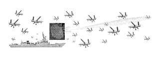
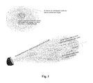
- FIG. 1 shows an arrayed-radar with multiple targets in a resolution cell
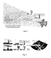
- FIG. 2 illustrates an example of sparsity-based processing for counter-stealth L-Band radar and EW applications
- FIG. 3 illustrates an example of sparsity-based processing for land based counter VLO radar applications
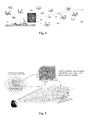
- FIG. 4 illustrates an example of an embodiment of the sparsity-based processing of the present invention applied to radar electronic counter-counter measure (ECCM) processing applications;
- ECCM radar electronic counter-counter measure
- FIG. 5 illustrates an example of a radar 3-D fine grid in excess range—azimuth—elevation space used in one embodiment of the sparsity-based processing of the present invention
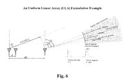
- FIG. 6 shows an example of an uniform linear array (ULA) formulation
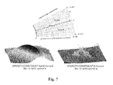
- FIG. 7 shows a comparative notational example of sparsity-based processing radar results on the right and conventional radar results on the left.
- the system and method of the present invention uses a sparse representation framework, which hereinafter is referred to as sparsity-based processing, ruining on one or more computers of a sensor system, to enhance target location estimation capabilities of the sensor system for one or more targets.
- the sparsity-based processing of the system and method of the present invention even enables enhanced target resolution performance for closely spaced targets in environments rich in multipath interference.
- the sparsity-based processing of the system and method of the present invention uses snapshots of the received signals and does not require the construction of a signal covariance, used in most traditional target location resolution and adaptive array techniques.
- the system and method of the present invention is tolerant to coherent interference (e.g. multipath and signal repeaters), and provides estimated locations for targets in all three dimensions—i.e. range, azimuth, and elevation with higher resolution, even in higher noise environments.
- the sparsity-based processing of the system and method of present invention uses snapshot samples of the received signals in an innovative new way to formulate and form a matrix for a target location estimation problem and solve the matrix by applying a sparse representation framework (i.e., sparsity-based processing) to resolve ambiguity in the received signals, improve the angular resolution accuracy (e.g., DoA accuracy) of the received signals, and improve the accuracy and performance of the sensor system for estimating a location of targets, even in environments having high coherent interference due to multipath and signal repeaters.
- the signal conversion to the frequency domain, frequency-domain division operations, search grid formulation, and angular and temporal ambiguity resolution processing for solving the sparse vector estimation problem are innovative concepts of the present invention.
- the disclosed unique formulation techniques frame a sensor target location problem into a sparsity estimation problem in which the target location can be solved using sparsity solvers with better resolution, by potentially an order of magnitude, than can be provided by existing sensor location techniques.
- the sparsity-based processing of the system and method of the present invention uses target information spanning spatial, temporal, and spectral domains, and constructs an innovative joint sparse DoA and multipath estimation model for resolving ambiguity in the DoA of received signals, including the reflected or echo signal from the targets and associated multipath replicas in signal transmitting sensor system embodiments.
- This novel modeling technique of the present invention enables the sparsity-based processing to apply sparsity solving techniques to resolve and estimate a location of a target.
- sparsity-based processing initially passively resolves signal ambiguity and estimates the location of each signal-of-interest as described in the following paragraphs.
- the processor(s) of the sensor system using sparsity-based processing establishes a 2-D (for linear array) or 3-D grid (for planar array) covering the defined area in which the targets were detected.
- the 2-D grid spans a single angular space and a multipath space and the 3-D grid spans two orthogonal angular space and a multipath space.
- the 2-D grid spans a single angular space and an excess range space and the 3-D grid spans two orthogonal angular space and an excess range space.
- each target is assumed to occupy a single grid point in the 2-D or 3-D grid, and the 2-D or 3-D grid is considered to be sparse because the number of grid points contained within the 2-D or 3-D grid is assumed to be much greater that the number of targets to be located in the defined area covered by the 2-D or 3-D grid.
- This embodiment of sparsity-based processing then takes one or more snapshots of the received signals in a snapshot collection window, converts these received signals in the time domain to received signals in the frequency domain, and normalize the frequency-domain signal with a frequency-domain reference signal.
- This unique frequency-domain snapshot processing approach re-casts the original target estimation problem into a linear estimation problem in which the map image represented by a solution vector is sparse in nature.
- the system and method of the present invention does not use or rely upon signal covariance based processing or Hankel matrix based processing, which advantageously removes limitations associated with signal covariance based processing and Hankel matrix based processing.
- the system and method of the present invention significantly improve range resolution and angular resolution performance of the sensor by potentially an order of magnitude.
- the sparsity-based processing of the present invention can also be applied to detail 3-D target imaging for classification purposes.
- the processing necessary for target position estimation of the present invention may significantly increase the amount of signal processing performed by the sensor system (signal processing bandwidth) to determine the location of the targets. In some sensor systems, this may require hardware upgrades to processing assets, as well as higher power consumption.
- the sensor system does not actively transmit a signal (e.g., remains passive) and the sparsity-based processing, using only azimuth and elevation data for the received signals, angularly, temporally, or spectrally separates the received signals, provides an coarse estimated direction of arrival for each signal of interest (SOI), and then estimates a finer location for each coarsely separated signal of interest, even when the coarsely separated SOI is coherently interfered.
- SOI signal of interest
- the passive DoA estimation problem relates to the electronic protection/electronic support (EP/ES) and signal intelligence (SKINT) missions, for example.
- Some examples of passive system embodiments include an electronic support measures (ESM) system or other arrayed signal receiving sensor system, such as towed-array sonars and cell phone location capabilities using cellular system cell tower transceivers.
- ESM electronic support measures
- an arrayed-sensor system initially receives signals transmitted by one or more signal transmitters at multiple receiving elements of the arrayed sensor system, and the present invention can passively resolve and estimate the location of each of signal transmitter (i.e., target) using only the existing arrayed receiving elements of the sensor system by enforcing sparsity constraints in the sparsity-based processing.
- the system and method of the present invention initially parses the received signals by taking snapshots of the received signals in snapshot collection windows, for example.
- the frequency of the snapshots and duration of the snapshot collection windows are variables selected by the sparsity-based processing based on the signal environment encountered.
- the sparsity-based processing converts each received signal in a snapshot from a received signal in the time domain to a received signal in the frequency domain.
- the converted received signals in the frequency domain are then normalized by dividing the received signal at each receiving element in the snapshot with a reference signal.
- the reference signal is the received signal of one of the elements of the sensor system array.
- the present invention now applies sparsity-based processing to the converted, normalized received signals in the frequency domain to resolve any ambiguity and separate the signal of interest from coherent interference.
- the combination of received signal conversion to the frequency domain, normalization, and sparsity formulation resolves the signal of interest, which travels from the target to the receiver via a direct line-of-sight (LOS) path, from multipath reflected signals and other signal repeaters present in the environment.
- the system and method of the present invention reformulates the target location estimation problem and provide an estimate of each signal transmitter (target) location by enforcing sparsity constraints, thereby enabling the benefits associated with enforcing the sparsity constraints to be realized.
- the reformulation of the target location estimation problem is discussed in detail in the arrayed-radar example.
- the sensor system actively transmits one or more signals and resolves the position of each target, even where the targets are closely spaced targets, in all three dimensions (i.e., range, azimuth and elevation) in high noise/signal interference environments. This is achieved by first locating the interfering signals using the passive sparsity-based processing, then apply spatial nulling, to suppress the interferences, and then detect targets by applying, the active sparsity-based processing.
- the active DoA estimation problem relates to radar target location missions, for example.
- Examples of active signal transmission sensor systems include an arrayed radar system having a linear, planar, phased or 3-D array, and sonar systems.
- the sensor system is a radar system
- the sparsity-based processing of the present invention enables the radar system to estimate a location for each target when multiple targets are in a single resolution cell of the radar system, even in the presence of large number of interfering signals, including jamming signals, and associated multipath signals, and repeated jamming signals, and associated multipath signals. This is achieved by first locating the interfering signals using the passive sparsity-based processing, then apply spatial nulling to suppress the interferences, and then detect targets by applying the active sparsity-based processing. In radar system applications, the sparsity-based processing improves the angle and range estimation accuracy and enhances the radar target location capabilities of the radar system.
- the new sparse representation framework (sparsity-based processing) of the present invention achieves higher target resolution and accuracy in the coherent interference environment using same radar front-end resources, and solves the radar target localization problem.
- the sparse representation framework is further extended to solve the wide-band signal transmitter, including signal jammers, localization problem, thereby, improving the electronic support/protection capabilities of radars.
- the sparse representation framework requires only snapshots of the received signals, does not use signal covariance, operates on fewer spatial degrees of freedom, and requires lower signal-to-noise power ratio compared to conventional approaches.
- the sparsity-based processing system and method of the present invention are applied to radar systems.
- an L-Band active electronically scanned array (AESA) radar can be used for acquiring stealth aircraft, as shown in FIG. 2 , but this radar has limited resolution and accuracy so it is not good for targeting the detected aircraft.
- AESA L-Band active electronically scanned array
- the sparsity-based signal processing of the present invention to counter-stealth L-band radar and electronic warfare applications, the targeting/weapon guidance of a non-friendly L-band AESA could be enhanced to pose an elevated threat to friendly very low observable (VLO) airframes.
- VLO very low observable
- the sparsity-based processing to a friendly Anti Radiation (AR) capability, the AR capability can be improved to provide an enhanced counter-counter stealth capability.
- AR Anti Radiation
- the number of signal transmitters is much greater (>>) than the number of array elements dedicated for adaptive digital beam forming, so the transmitted signals present in the environment would overwhelm the adaptive digital beam forming capability of the arrayed-radar, causing the arrayed-radar to fail to adaptively null out these signals (including jamming signals, if present) and fail to locate the signal transmitters (including signal jammers, if present).
- the sparsity-based processing of the present invention to the radar electronic counter-counter measure (ECCM) application of the arrayed-radar would enable the arrayed-radar to resolve ambiguities in the received signals, improve DoA data for the received signals, and estimate the locations of targets and the signal transmitters transmitting known and unknown signal waveforms.
- the system and method of the present invention can enable the arrayed radar to provide estimated locations of targets even when intentional signal jamming is present.
- the sparsity-based processing of the present invention is implemented as a radar system back-end upgrade to improve the performance of legacy radar systems by replacing the back-end signal processing capability to include the state-of-the-art sparsity-based processing capabilities of the present invention.
- simply replacing the signal processor to include sparsity-based processing of the present invention enables existing system hardware to meet new requirements and/or new mission modes.
- the sparsity-based processing of the present invention is implemented as a radar detection capability enhancement for improving lower-band (e.g. L-band, S-band) radar resolution and to provide a preliminary target discrimination capability that is currently only available in higher-frequency radar systems (e.g. X-band) and higher bandwidth signals.
- lower-band e.g. L-band, S-band
- X-band higher-frequency radar systems
- the sparsity-based processing of the present invention enhances the electronic protection/support capability of existing sensor system by providing more accurate identification and location of signal sources, including jamming and interference sources, using fewer dedicated system resources than required using more traditional techniques.
- the new sparsity-based processing will enable existing radar systems to meet new EP/ES requirements without modifying the front-end architecture of the sensor system.
- the sparsity-based processing of the radar system can not only be applied for detecting and locating closely spaced or clustered targets, but can also be applied for detecting counter-stealth radars, and detecting stealth aircraft via a multi-static radar network.
- the sparsity-based processing of the present invention is used with sensors having smaller sensor arrays to provide target location performance equal to sensor system having much larger sensor arrays.
- the sparsity-based processing of the present invention can be applied to more precisely detail the 3-D target imaging for classification purposes, with resolution high enough to resolve individual structural parts of the target.
- the sparsity-based processing of the present invention does not require changes to the physical specifications of the receiving and transmitting elements of an arrayed-radar, the processing capabilities may require a significant increase in signal processing bandwidth, potentially requiring more powerful hardware processing assets and higher power consumptions.
- the sparsity-based processing can be used to reduce the physical size of existing radars while maintaining the original performance specifications.
- multiple targets of interest are present in a single radar resolution cell, as shown in FIG. 1 , in an environment including a plurality of signals and associated coherent interference, and the arrayed-radar is unable to determine the number of target or determine a location for each of the targets present in the resolution cell.
- the process starts with first locating the interfering signals using the passive sparsity-based processing, then apply spatial nulling to suppress the interferences, and then locate targets with higher resolution by applying the active sparsity-based processing.
- the arrayed-radar initially employs sparsity-based processing and enforces sparsity constraints to passively resolve and estimate the location of each of the signal of interest (and signal jammers, if present) using the existing radar sub-arrays and auxiliary elements based on snapshots of the received transmitted signals (and jamming signals, if present) taken in defined snapshot collection windows and the known radar waveform transmitted by the radar system.
- whether the transmitted signals have a known or unknown signal waveform is not determinative to solving and estimating the location of the signal transmitters (and signal jammers, if present).
- a preprocessing is performed to separate signals of interest in spatial domain (such as using beam forming to separate signals coming from difference angles), temporal domain (for separating transient signals offset in time, typical to wideband pulsed signals), and frequency domain (for separating signals offset in frequency or differing in Doppler shifts) such that in each of the resulting separated signal, at most one signal of interest and associated coherent interferences may be present.
- spatial domain such as using beam forming to separate signals coming from difference angles
- temporal domain for separating transient signals offset in time, typical to wideband pulsed signals
- frequency domain for separating signals offset in frequency or differing in Doppler shifts
- the number of radar sub-arrays and auxiliary elements do not need to be greater than the number of signal transmitters (and signal jammers, if present) encountered, and a tap-delay space-time covariance is not necessary to de-correlate known or unknown signal waveforms (and jamming signals, if present) from multipath, background clutter or, even a concerted electronic counter measure (ECM) attack (i.e. signal repeaters).
- ECM electronic counter measure
- embodiments of the system and method of the present invention convert the received signals in the time domain to received signals in the frequency domain, then normalize the received signals in the frequency domain by dividing each received signal in the snapshot by a reference signal.
- the reference signal can be a received signal at one of the receiving elements in the array.
- the received signals and the reference signal when a received signal is used as the reference signal, may contain coherent interference including multipath, the normalized received signals in the frequency domain may include ambiguity in the angular and temporal space.
- the next step is for the radar system to suppress the interfering signals transmitted from the estimated locations. Then, the radar system using the sparsity-based processing estimates the location of any targets of interest after the removal of interfering signals.
- An example of the sparsity-based processing for resolving and estimating the location of targets of interest is discussed in more detail in the next section of the specification
- the sparsity-based processing of the present invention establishes a fine 3-D grid covering the detection resolution cell containing the detected targets.
- the 3-D grid established by the present invention in this radar example has a sufficiently small grid resolution to separate and locate each of the targets within the single resolution cell.
- 3-D map image 3-D fine azimuth-elevation-excess range map
- the sparsity-based processing then uses a unique frequency-domain snapshot processing approach that re-casts the original target DoA estimation problem into a linear angle-excess range estimation problem in which a solution vector represented on the 3-D map image is sparse.
- the sparsity-based processing then applies a sparsity solver employing advanced sparse solution estimation techniques for finding the sparse solution precisely.
- the sparsity solver uses a combination of L1-norm minimization, a variable splitting technique and an augmented Lagrangian technique to efficiently form a 3-D map image and solve for the location of the targets of interest.
- the resulting 3-D map image reveals the refined angular and range positions of the targets of interest within the detection cell.
- the 3-D image of the K ⁇ L search space for each of the one or more estimated target vectors is formed relative to the earliest arriving received energy signal for that target using the azimuth angle, elevation angle and excess delay of each element having the energy level above the predetermined energy threshold level for each of the one or more estimated target vectors.
- FIG. 5 An example of a 3-D map image used in the sparsity-based processing of the present invention is shown in FIG. 5 .
- the sparse solution vector x is the size of the 3-D map image, and the number of rows of A (and the length of the y vector) must be greater than the number of detectable targets when the sparsity constraints are enforced. However, the number of rows of A (and the length of the y vector) do not need to be equal or greater than the size of the sparse solution vector x, only greater than the number of detectable targets when the sparsity constraints are enforced.
- the output signal by the n-th element is represented by the following equation:
- the form of the received reflected signal, s(t) is dependent on the transmitted radar waveform and any channelization and Doppler filtering applied to the received reflected signal with respect to the detected angular-range-Doppler bin.
- pulse compression if applied needs to be considered as well.
- the sparsity-based processing of the present invention converts the received signal s(t), which is a received signal in the time domain to a received signal in the frequency domain.
- the received signal at the nth receiving element, S n (t) is represented by the following equation:
- the received reflected signal in the frequency domain is then divided with the known radar signal in the frequency domain, as shown in the following equation;
- the sparsity-based processing forms a total of N ⁇ M r n,m measurement equations.
- the sparsity-based processing sets up a refined search grid around a small area within the 3-D grid, based on available angular and range data.
- the angular and range data are a look angle ⁇ , and an associated range R:
- the refined search grid is a search space covering an area of dimensions K ⁇ L (i.e., K ⁇ L search space).
- the sparsity-based processing then forms the following matrix based on the N ⁇ M measurement equations of vector y and the K ⁇ L search space:
- a sparse solution of x exists when P ⁇ KL where only P elements of the KL elements of x have values above the noise floor.
- the sparsity-based processing then forms a 3-D target location map image (3-D map image) of the K ⁇ L search space with the solution of x.
- the sparsity-based processing uses using a highly efficient sparsity solver employing L ⁇ 1 norm minimization, variable splitting and augmented Lagrangian techniques to solve for x.
- the signal conversion to the frequency domain, frequency-domain division operations, and search grid formulation for solving the sparse vector estimation problem are innovative concepts of the present invention.
- the disclosed unique formulation techniques frame a radar target location problem into a sparsity estimation problem in which the target location can be solved using known sparsity solvers with better resolution, by potentially an order of magnitude, than can be provided by existing radar location techniques.
- the example sparsity solver is described in more detail in the next section.
- the sparsity solver uses L ⁇ 1 norm minimization as described in the following paragraphs.
- equation (1) can be solved for x, if x is sparse and the elements of n are independent Gaussian random variables with zero mean and same variance ⁇ ′.
- the sparsity solver estimates x using the following equations:
- x est argmin x ⁇ ⁇ x ⁇ 1 ⁇ ⁇ such ⁇ ⁇ that ⁇ ⁇ ⁇ y - Ax ⁇ 2 ⁇ ⁇ ′ ⁇ N y ⁇ ⁇ ( 7 )
- N y is the dimension of y and ⁇ ′ is to be numerically determined.
- x est argmin x ⁇ ( ⁇ x ⁇ 1 + l ⁇ ′ ⁇ ( y - Ax ) ) ( 8 )
- the sparsity solver then uses a variable splitting technique to reformulate equation (8) above into a new constrained optimization problem as shown below:
- the sparsity solver applies an Augmented Lagrangian technique to reformulate the constrained optimization problem represented by equation (10) into the following equation:
- ⁇ x est , v est , s est ⁇ argmin x , v , s ⁇ ( ⁇ v ⁇ 1 + l ⁇ ′ ⁇ ( s ) + ⁇ 1 ⁇ ⁇ v - x - d 1 ⁇ 2 2 + ⁇ 2 ⁇ ⁇ y - Ax - s - d 2 ⁇ 2 2 ) ⁇ ⁇ ⁇ update ⁇ : ⁇ ⁇ d 1 ⁇ d 1 - ( v est - x est ) ⁇ ⁇ ⁇ update ⁇ : ⁇ ⁇ d 2 ⁇ d 2 - ( y - Ax est - s est ) ( 11 )
- the sparsity solver then iteratively solves equation (11) using the process shown below:
- ⁇ s est ⁇ y - Ax est - d 2 if ⁇ ⁇ y - Ax est - d 2 ⁇ 2 ⁇ ⁇ ′ ⁇ ⁇ y - Ax est - d 2 ⁇ y - Ax est - d 2 ⁇ 2 if ⁇ ⁇ y - Ax est - d 2 ⁇
- the outputs of this iterative solution process are values for v est , s est , and x est , which define the estimated location of the target.
- the received signal at one receiving element of the sensor system is selected as the reference signal and reference element, respectively.
- the sparsity-based processing of the system and method present invention uses the known waveform of the transmitted signal as the reference signal.
- the number of signal transmitters in the environment can be greater that the number of receiving elements of the arrayed-sensor system, and a tap-delay space-time covariance is not necessary to de-correlate known and unknown signal waveforms from multipath, background clutter or, even a concerted electronic counter measure (ECM) attack.
- ECM electronic counter measure
- a preprocessing is performed to separate signals of interest in spatial domain (such as using beam forming to separate signals coining from difference angles), temporal domain (for separating transient signals offset in time, typical to wideband pulsed signals), and frequency domain (for separating signals offset in frequency or differing in Doppler shills) such that in each of the resulting separated signal, at most one signal of interest and associated coherent interferences may be present.
- the sparsity-based processing then enforces sparsity constraints to estimate a location for each signal transmitter (and signal jammer, if present).
- This methodology can be used by both passive receive only systems, such as ESM, and active transmission capable systems, such as a radar that is not transmitting and is operating in a receive-only mode (i.e., passive mode) for estimating the locations of the actively transmitting signal sources, including signal jammers and associated multipath signal arrivals.
- the passive DoA estimation problem relates to the EP/ES and SIGINT missions, for example.
- the sparsity-based processing normalizes the received signal by dividing the received signal by a signal, referred to as a reference signal.
- the reference signal is used in the denominator for the frequency-domain division operations.
- the reference signal used is an output signal from one receiving element or a sub-array of the arrayed-radar.
- the frequency-domain division operations are then similar to the frequency-domain division operations for the known transmitted signal case discussed in a previous section.
- the passive estimation of the direction of a signal of interest is an extension of the first innovative concept of the present invention. For example, assuming that only one signal have an unknown waveform is transmitted by one transmitting signal source (or only one jamming signal is transmitted by a single signal jammer) and only the transmitted signal and its associated multipath are received in the signal snapshot collection window, the direction of the transmitting signal source (or signal jammer) and its multipath is estimated using the following process. The processing for this example direction estimation of the signal of interest (SOI) is discussed in more detail in the following section.
- the sparsity-based processing views the SOT and its multipath as a plane wave.
- the received signals by the n-th element of a uniform linear array (ULA) of the radar is modeled as:
- the SOI received at the n-th element is represented by the following equation:
- the sparsity-based processing selects one of the receiving elements of the array, for this example receiving element n0, as the reference element, and its frequency domain signal is represented by the following equation: s n0 ( f m ) (18)
- the sparsity-based processing sets up a smaller search grid around an angular measurement and a signal delay measurement determined for the received signal-of-interest.
- the search grid is set up for angle ⁇ and delay ⁇ :
- the sparsity-based processing forms frequency-domain measurement ratio equations for the received signals in the frequency domain around angle ⁇ and delay ⁇ , the frequency-domain measurement ratio equations is written in the following form:
- the sparsity-based processing calculates all of the possible values for the equation term ( ⁇ k ⁇ t n,1 ), and sorts the calculated values for the equation term ( ⁇ k ⁇ t n,1 ) in an ascending order from small to large. This also sorts the corresponding amplitude values ⁇ from low to high.
- the calculated values for ( ⁇ k ⁇ t n,1 ) are then denoted as shown below: ⁇ n,1 , ⁇ n,2 , . . . , ⁇ n,V ⁇ (21)
- V KL and the corresponding amplitudes are denoted as ⁇ 1 , ⁇ 2 , . . . , ⁇ V ⁇ , which belong to the set of amplitudes ⁇ , and
- r n , m ⁇ 1 ⁇ e - j2 ⁇ ⁇ ⁇ f m ⁇ ⁇ n ⁇ .1 + ⁇ 2 ⁇ e - j2 ⁇ ⁇ ⁇ f m ⁇ ⁇ n ⁇ .2 + ... + ⁇ V ⁇ e - j2 ⁇ ⁇ ⁇ f m ⁇ ⁇ n .
- V V ⁇ 1 ⁇ e - j2 ⁇ ⁇ ⁇ f m ⁇ ⁇ n ⁇ ⁇ 0.1 + ⁇ 2 ⁇ e - j2 ⁇ ⁇ ⁇ f m ⁇ ⁇ n ⁇ ⁇ 0.2 + ... + ⁇ V ⁇ e - j2 ⁇ ⁇ ⁇ f m ⁇ ⁇ n ⁇ ⁇ 0.
- ⁇ V ⁇ 1 ⁇ Z m - ⁇ n ⁇ .1 + ⁇ 2 ⁇ Z m - ⁇ n ⁇ .2 + ... + ⁇ V ⁇ Z m - ⁇ n .
- the sparsity-based processing then solves for ⁇ , where the solution of ⁇ is spanned by the null space of ⁇ , and the correct solution is a sparse ⁇ that is also non-trivial (not all zeros).
- the arrival angle and delay of the SOI will correspond to the ⁇ having a significant value with the smallest delay in this example.
- FIG. 7 An example is shown in FIG. 7 of notional radar results using the sparsity-based processing of the present invention (on the right side) and conventional radar results (on the left side) for comparison.
- the formulation of the problem and solution can be easily expanded to apply to a planar array or a 3D array. Further, the sparsity-based processing problem formulation and solution is also applicable to arrayed-sensors in which the array elements are arbitrary not uniform.
Landscapes
- Engineering & Computer Science (AREA)
- Radar, Positioning & Navigation (AREA)
- Remote Sensing (AREA)
- Physics & Mathematics (AREA)
- General Physics & Mathematics (AREA)
- Computer Networks & Wireless Communication (AREA)
- Measurement Of Velocity Or Position Using Acoustic Or Ultrasonic Waves (AREA)
- Radar Systems Or Details Thereof (AREA)
Abstract
Description
{εn,1,εn,2 . . . εn,V}
where V=KL and the corresponding amplitudes are denoted as {β1, β2, . . . βV}, which belong to the set of amplitudes α, and the terms corresponding to (τk−Δtn0,1) are now denoted as {εn0,1, εn0,2, . . . εn0,V}, and are arranged based on the sorting sequence of the calculated values for (τk−Δtn,1) and are not necessarily in an ascending order, rearranges the spectrum ratio equation using the new notations to obtain the following homogeneous spectrum ratio equation in matrix vector form,
-
- where
- ρi=βi1/βU and i≠U
- φjmε{φim's, i≠U}
- where
Ax=y
where x is a solution vector, A is a matrix of known functions, and y is a vector from observation. The at least one processor using a sparse representation framework then forms a number of measurement equations, the number of measurement equation being equal to N×M, where N is the number of outputs from receiving elements of the sensor array, and M is the number of frequency sampling points available, forms a matrix based on the N×M measurement equations for the solution vector y and a K×L search space in the 3-D grid, forms a 3-D image of the K×L search space, where the solution vector x for the target on the 3-D image is sparse when a number of grid points within the K×L search space is much greater than a number of grid points P having a value above a noise floor of the K×L search space (KL>>P), and applies the sparsity solver to solve the matrix for the solution vector x to estimate the location of the target. In some of these embodiments, the measurement equations are matrix-vector equations represented in a form of, an active signal model matrix*target vector=measurement vector, where the active signal model matrix is constructed using an array model of the receiving element of the sensor system and a 3-D search grid covering azimuth, elevation, and excess range dimensions of the resolution cell in which the target was detected, the target vector is a sparse vector to be estimated, and the measurement vector includes a sampling of the received energy signals in the frequency domain, and the 3-D image of the K×L search space for the estimated target vector is formed relative to the earliest arriving received energy signal for the target using the azimuth angle, elevation angle and excess delay of each element having the energy level above the predetermined energy threshold level for the estimated target vector.
where a sparse solution of x exists when P<<KL where only P elements of the KL elements of x have values above the noise floor, an estimated location of the target on the 3-D map image of the K×L search space is formed with the solution of x, and the sparsity solver estimates a location of the target by solving the matrix for the solution vector x, where the following constraints are satisfied the solution vector x for the target on the 3-D image is sparse, and a number of grid points within the K×L search space is much greater than a number of grid points P having a value above a noise floor of the K×L search space (KL>>P).
∥y−Hx∥ 2≦σ′, and
and
-
- 1. choose μ1 and μ2 and initialize xest, d1 and d2
- 2. solve
-
- 3. updated: d1←d1−(vest−xest)
- update: d2←d2−(y−Axest−sest)
- 4. and repeat steps 1-3 until the location of the target is estimated.
the sparsity solver solves for β, and estimates a location of the interfering transmitter transmitting the interfering signal, where the solution of β is spanned by the null space of φ, a correct β is sparse, and β cannot be zero.
Ax=y
where x is a solution vector, A is a matrix of known functions, and y is a vector from observation. The at least one processor using a sparse representation framework then forms a number of measurement equations, the number of measurement equation being equal to N×M, where N is the number of outputs from receiving elements of the sensor array, and M is the number of frequency sampling points available, forms a matrix based on the N×M measurement equations for the solution vector y and a K×L search space in the 3-D grid, forms a 3-D image of the K×L search space, where the solution vector x for the target on the 3-1) image is sparse when a number of grid points within the K×L search space is much greater than a number of grid points P having a value above a noise floor of the K×L search space (KL>>P), and applies the sparsity solver to solve the matrix for the solution vector x to estimate a location of the target.
and solving for β using the sparsity solver to estimate a location of the target transmitting the signal-of-interest where the solution of β is spanned by the null space of φ, a correct β is sparse, and β cannot be zero.
solving for ρi, which is a function of β and βu, as shown below:
and applying at least one known sparsity estimation approach to estimate a location of the target transmitting of the signal-of-interest where ρi is sparse, and an angle of arrival and delay τ of each signal-of-interest corresponds to the ρi having a significant value with the smallest delay τ.
Ax=y
where x is a solution vector, A is a matrix of known functions, and y is a vector from observation. The method further comprises forming a number of measurement equations, the number of measurement equation being equal to N×M, where N is the number of outputs from receiving elements of the sensor array, and M is the number of frequency sampling points available, forming a matrix based on the N×M measurement equations for the solution vector y and a K×L search space in the 3-D grid, forming a 3-D image of the K×L search space, where the solution vector x for the target on the 3-D image is sparse when a number of grid points within the K×L search space is much greater than a number of grid points P having a value above a noise floor of the K×L search space (KL>>P), and solving the matrix for the solution vector x using the sparsity solver to estimate the location of the target.
where a sparse solution of x exists when P<<KL where only P elements of the KL elements of x have values above the noise floor, an estimated location of the target on the 3-D map image of the K×L search space is formed with the solution of x, and solving the matrix for the solution vector x using the sparsity solver to estimate the location of the target, where the following constraints are satisfied the solution vector x for the target on the 3-D image is sparse, and a number of grid points within the K×L search space is much greater than a number of grid points P having a value above a noise floor of the K×L search space (KL>>P).
where: the indicator function l is defined as follows:
where: a solution of the unconstrained optimization problem must satisfy
∥y−Hx∥ 2≦σ′; and
applies a combination of at least two techniques to solve the unconstrained optimization problem to estimate the location of the target.
reformulating the constrained optimization problem shown above as follows:
where μ1 and μ2 are some positive numbers.
and iteratively solving the reformulated equation for values of xest, vest, sest to estimate the location of the target.
and iteratively solving these equations using the following procedure:
-
- 1. choose μ1 and μ2 and initialize xest, d1 and d2
- 2. solve
-
- 3. updated: d1←d1−(vest−xest)
- update: d2←d2−(y−Axest−sest)
- 4. and repeat steps 1-3 until locations for each of the one or more targets are estimated.
{εn,1,εn,2, . . . εn,V}
where V=KL and the corresponding amplitudes are denoted as {β1, β2, . . . , βV}, which belong to the set of amplitudes α, and the terms corresponding to (τk−Δtn0,1) are now denoted as {εn0,1, εn0,2, . . . , εn0,V}, and are arranged based on the sorting sequence of the calculated values for (τk−Δtn,1) and are not necessarily in an ascending order, rearranging the spectrum ratio equation using the new notations to obtain the following homogeneous spectrum ratio equation in matrix vector form;
and solving for β using the sparsity solver to estimate a location of the interfering transmitter transmitting the interfering signal, where the solution of β is spanned by the null space of φ, a correct β is sparse, and β cannot be zero.
Ax=y
where x is a solution vector, A is a matrix of known functions, and y is a vector from observation. The method further comprises forming a number of measurement equations, the number of measurement equation being equal to N×M, where N is the number of outputs from receiving elements of the sensor array, and M is the number of frequency sampling points available, forming a matrix based on the N×M measurement equations for the solution vector y and a K×L search space in the 3-D grid, forming a 3-D image of the K×L search space, where the solution vector x for the target on the 3-D image is sparse when a number of grid points within the K×L search space is much greater than a number of grid points P having a value above a noise floor of the K×L search space (KL>>P), and solving the matrix for the solution vector x using the sparsity solver to estimate the location of the target.
-
- Non covariance based processing;
- No loss of effective aperture (no spatial smoothing, no Hankel matrix);
- Improved emitter localization capability in rich coherent inference environment; and
- Improved 3-D resolution (angular and range dimensions).
Ax=y (1)
where:
-
- x is the sparse solution vector,
- A is a matrix of known functions, and
- y is a vector from observation.
-
- Sn,i(t) is the received reflected signal from the i-th target received at the n-th receiving element;
- αi is the amplitude of the received signal from ith target at arrival angle θi;
- s is transmitted radar signal frequency;
- t is time;
- γi is excess range to ith target;
- C is the speed of light;
- τi is describes delayed and attenuated components of received signal, and
- Δtn,i is time delay of reflected signal from ith target at the n-th receiving element.
∥y−Hx∥ 2≦σ′.
-
- 1. choose μ1 and μ2 and initialize xest, d1 and d2
- 2. solve
-
- 3. update: d1←d1−(vest−xest)
- updated: d2←d2−(y−Axest−sest)
- 4. and repeat
-
- sn(t) is the signal of interest received at the n-th element;
- n is the number of receiving elements;
- d is the spacing of receiving elements;
- θi is the arrival angle of the signal, where i=indicates the SOI and where I>1 indicates a multipath signal;
- C is the speed of light, and
- αi is the amplitude of the θi path.
s n0(f m) (18)
-
- θ1=θ1 . . . θL
- τk=τ1 . . . τK
-
- rn,m is the spectrum ratio;
- θl is the angle of the search space;
- τk is the signal delay; and
- Δtn,1 is the time of received signal at n-th receiving element.
{εn,1,εn,2, . . . , εn,V} (21)
-
- the terms corresponding to (τk−Δtn0,1) are denoted as {εn0,1, εn0,2, . . . εn0,V}, which are arranged based on the sorting sequence of the calculated values for (τk−Δtn,1) and are not necessarily in an ascending order.
β1φ1m+β2φ2m+ . . . +βVφVm=0 where φim=(r n,m Z m −ε
and then solves equation (25) for each ρi, which is formed as a ratio of a member of β (excluding βU) and βU, as shown below:
-
- ρi=βi1/βU and i≠U
- φjmε{φim's, i≠U}
Claims (12)
{εn,1,εn,2 . . . εn,V}
Ax=y
{εn,1,εn,2 . . . εn,V}
Ax=y
Priority Applications (1)
| Application Number | Priority Date | Filing Date | Title |
|---|---|---|---|
| US14/060,001 US9562968B2 (en) | 2012-10-22 | 2013-10-22 | Sensor system and method for determining target location using sparsity-based processing |
Applications Claiming Priority (2)
| Application Number | Priority Date | Filing Date | Title |
|---|---|---|---|
| US201261716724P | 2012-10-22 | 2012-10-22 | |
| US14/060,001 US9562968B2 (en) | 2012-10-22 | 2013-10-22 | Sensor system and method for determining target location using sparsity-based processing |
Publications (2)
| Publication Number | Publication Date |
|---|---|
| US20140111372A1 US20140111372A1 (en) | 2014-04-24 |
| US9562968B2 true US9562968B2 (en) | 2017-02-07 |
Family
ID=49546625
Family Applications (1)
| Application Number | Title | Priority Date | Filing Date |
|---|---|---|---|
| US14/060,001 Expired - Fee Related US9562968B2 (en) | 2012-10-22 | 2013-10-22 | Sensor system and method for determining target location using sparsity-based processing |
Country Status (2)
| Country | Link |
|---|---|
| US (1) | US9562968B2 (en) |
| WO (1) | WO2014066360A1 (en) |
Cited By (13)
| Publication number | Priority date | Publication date | Assignee | Title |
|---|---|---|---|---|
| CN107092005A (en) * | 2017-06-16 | 2017-08-25 | 中国电子科技集团公司第二十九研究所 | A kind of united array processing method of space-time and device |
| CN110361703A (en) * | 2019-07-16 | 2019-10-22 | 广州市高峰科技有限公司 | The radar electric anticluter of integrated side-lobe blanking and sidelobe cancellation |
| CN110531312A (en) * | 2019-08-29 | 2019-12-03 | 深圳市远翰科技有限公司 | A kind of DOA estimation method and system based on sparse symmetric matrix column |
| US11284338B2 (en) * | 2017-03-17 | 2022-03-22 | Alcatel Lucent | Hidden node discovery for multiple-input-multiple-output (MIMO) in unlicensed frequency bands |
| US20220229173A1 (en) * | 2021-01-08 | 2022-07-21 | The Boeing Company | Complex recurrent neural network for synthetic aperture radar (sar) target recognition |
| US20220236399A1 (en) * | 2021-01-27 | 2022-07-28 | Texas Instruments Incorporated | System and method for the compression of echolocation data |
| US20220276369A1 (en) * | 2019-07-24 | 2022-09-01 | Sony Group Corporation | Radar device, processing device, calculation method, and calculation program |
| US11573311B2 (en) * | 2018-04-05 | 2023-02-07 | Google Llc | Smart-device-based radar system performing angular estimation using machine learning |
| US20230168212A1 (en) * | 2020-04-27 | 2023-06-01 | Signify Holding B.V. | Horticulture system and method |
| US11693104B2 (en) | 2017-12-15 | 2023-07-04 | Google Llc | Radar angular ambiguity resolution |
| US12250007B2 (en) | 2015-08-19 | 2025-03-11 | Texas Instruments Incorporated | Method and system for compression of radar signals |
| US12255411B2 (en) | 2020-12-16 | 2025-03-18 | Industrial Technology Research Institute | Frequency reconfigurable phased array system and material processing method performed thereby |
| RU2849973C1 (en) * | 2025-02-18 | 2025-11-01 | Федеральное государственное бюджетное образовательное учреждение высшего образования "Рязанский государственный радиотехнический университет имени В.Ф. Уткина" | Computer-interference rejector |
Families Citing this family (100)
| Publication number | Priority date | Publication date | Assignee | Title |
|---|---|---|---|---|
| US9857463B2 (en) * | 2012-11-12 | 2018-01-02 | Sony Corporation | Radar apparatus and method |
| US9885777B2 (en) * | 2014-01-10 | 2018-02-06 | Raytheon Company | Detection of stealth vehicles using VHF radar |
| US9489582B2 (en) | 2014-01-27 | 2016-11-08 | Xerox Corporation | Video anomaly detection based upon a sparsity model |
| WO2016137536A1 (en) * | 2014-10-21 | 2016-09-01 | Sikorsky Aircraft Corporation | Compressive wireless sensing for rotor loads and motion |
| US9689976B2 (en) * | 2014-12-19 | 2017-06-27 | Xidrone Systems, Inc. | Deterent for unmanned aerial systems |
| US9715009B1 (en) | 2014-12-19 | 2017-07-25 | Xidrone Systems, Inc. | Deterent for unmanned aerial systems |
| CN104539340B (en) * | 2014-12-26 | 2018-03-13 | 南京邮电大学 | A kind of sane direction of arrival estimation method being fitted based on rarefaction representation and covariance |
| CN105259545B (en) * | 2015-05-07 | 2018-04-06 | 电子科技大学 | Distributed true and false bullet recognition methods based on hard decision |
| CN105425234B (en) * | 2015-10-30 | 2017-11-21 | 西安电子科技大学 | RANGE-DOPPLER IMAGING method based on multitask Bayes's compressed sensing |
| CN106936552B (en) * | 2015-12-30 | 2020-04-03 | 上海无线通信研究中心 | Uplink pilot sequence allocation method and base station in massive MIMO system |
| US10261179B2 (en) | 2016-04-07 | 2019-04-16 | Uhnder, Inc. | Software defined automotive radar |
| US9846228B2 (en) | 2016-04-07 | 2017-12-19 | Uhnder, Inc. | Software defined automotive radar systems |
| WO2017175190A1 (en) | 2016-04-07 | 2017-10-12 | Uhnder, Inc. | Adaptive transmission and interference cancellation for mimo radar |
| CN106021637B (en) * | 2016-04-15 | 2019-02-19 | 山东农业大学 | A DOA Estimation Method Based on Iterative Sparse Reconstruction in Coprime Arrays |
| EP3449275B1 (en) | 2016-04-25 | 2025-08-20 | Robert Bosch GmbH | Pmcw-pmcw interference mitigation |
| US9954955B2 (en) | 2016-04-25 | 2018-04-24 | Uhnder, Inc. | Vehicle radar system with a shared radar and communication system |
| US9945935B2 (en) | 2016-04-25 | 2018-04-17 | Uhnder, Inc. | Digital frequency modulated continuous wave radar using handcrafted constant envelope modulation |
| WO2017187242A1 (en) * | 2016-04-25 | 2017-11-02 | Uhnder, Inc. | On-demand multi-scan micro doppler for vehicle |
| US9791551B1 (en) | 2016-04-25 | 2017-10-17 | Uhnder, Inc. | Vehicular radar system with self-interference cancellation |
| US9806914B1 (en) | 2016-04-25 | 2017-10-31 | Uhnder, Inc. | Successive signal interference mitigation |
| US9575160B1 (en) | 2016-04-25 | 2017-02-21 | Uhnder, Inc. | Vehicular radar sensing system utilizing high rate true random number generator |
| US9791564B1 (en) | 2016-04-25 | 2017-10-17 | Uhnder, Inc. | Adaptive filtering for FMCW interference mitigation in PMCW radar systems |
| WO2017187341A1 (en) | 2016-04-25 | 2017-11-02 | Uhnder, Inc. | Vehicle radar system using shaped antenna patterns |
| US9753121B1 (en) | 2016-06-20 | 2017-09-05 | Uhnder, Inc. | Power control for improved near-far performance of radar systems |
| CN106230517B (en) * | 2016-07-01 | 2018-11-09 | 江苏科技大学 | A kind of underwater tracking exchage anti-interference processing method |
| US10545232B2 (en) * | 2016-08-24 | 2020-01-28 | Mitsubishi Electric Research Laboratories, Inc. | System and method for radar imaging using distributed moving platforms under unknown position perturbations |
| WO2018051288A1 (en) | 2016-09-16 | 2018-03-22 | Uhnder, Inc. | Virtual radar configuration for 2d array |
| US10511392B2 (en) * | 2016-10-14 | 2019-12-17 | Board Of Regents, The University Of Texas System | Systems, methods, and computer programs for wireless local area network localization |
| JP2018096838A (en) * | 2016-12-13 | 2018-06-21 | 株式会社東芝 | Rader system, signal processor, and method for processing signal |
| US10908272B2 (en) | 2017-02-10 | 2021-02-02 | Uhnder, Inc. | Reduced complexity FFT-based correlation for automotive radar |
| WO2018146633A1 (en) | 2017-02-10 | 2018-08-16 | Uhnder, Inc. | Programmable code generation for radar sensing systems |
| US11454697B2 (en) | 2017-02-10 | 2022-09-27 | Uhnder, Inc. | Increasing performance of a receive pipeline of a radar with memory optimization |
| JP2018159575A (en) * | 2017-03-22 | 2018-10-11 | 株式会社デンソー | Radar system |
| CN106970374B (en) * | 2017-05-27 | 2019-05-07 | 中国人民解放军63892部队 | The measurement method of Monopulse Radar Target and interference source angle under disturbed condition |
| US11105890B2 (en) | 2017-12-14 | 2021-08-31 | Uhnder, Inc. | Frequency modulated signal cancellation in variable power mode for radar applications |
| US12386029B2 (en) | 2018-01-29 | 2025-08-12 | Robert Bosch Gmbh | Millimeter wave automotive radar systems |
| US11194014B1 (en) | 2018-02-22 | 2021-12-07 | United States Of America As Represented By The Secretary Of The Air Force | System, method and apparatus for recovering polarization radar data |
| CN108363048B (en) * | 2018-03-06 | 2021-10-19 | 中国人民解放军空军工程大学 | An Angle Estimation Method for Polarized MIMO Radar Based on Block Sparse |
| JP7031495B2 (en) * | 2018-05-24 | 2022-03-08 | 株式会社デンソー | Signal processing equipment |
| US11953584B2 (en) * | 2018-07-06 | 2024-04-09 | University Of Massachusetts | Three-dimensional location estimation using multiplicative processing of sensor measurements |
| US11474225B2 (en) | 2018-11-09 | 2022-10-18 | Uhnder, Inc. | Pulse digital mimo radar system |
| CN109738852B (en) * | 2018-12-15 | 2022-12-16 | 华南理工大学 | Estimation Method of Distributed Source Two-Dimensional Spatial Spectrum Based on Low-rank Matrix Reconstruction |
| CN111381208B (en) * | 2018-12-29 | 2021-11-09 | 西安电子科技大学 | Method for estimating direction of arrival of known waveform information source |
| WO2020183392A1 (en) | 2019-03-12 | 2020-09-17 | Uhnder, Inc. | Method and apparatus for mitigation of low frequency noise in radar systems |
| US11520030B2 (en) | 2019-03-18 | 2022-12-06 | Nxp Usa, Inc. | High resolution automotive radar system with forward and backward difference co-array processing |
| US11092683B2 (en) | 2019-03-18 | 2021-08-17 | Nxp Usa, Inc. | Distributed aperture automotive radar system with alternating master radar devices |
| US11269049B2 (en) | 2019-03-18 | 2022-03-08 | Nxp Usa, Inc. | Distributed aperture automotive radar system |
| CN111726191B (en) * | 2019-03-21 | 2024-07-02 | 中兴通讯股份有限公司 | Signal processing method, apparatus and computer readable storage medium |
| JP7252052B2 (en) * | 2019-05-13 | 2023-04-04 | 株式会社デンソーテン | MIMO radar device and signal processing method |
| CN110082710B (en) * | 2019-05-15 | 2023-05-26 | 苏州经贸职业技术学院 | Two-dimensional Angle of Arrival Estimation Method Based on Sparse Arrays with Lattice-Free Atom Norm |
| CN110174651B (en) * | 2019-05-16 | 2022-11-18 | 河海大学 | Meteorological radar wind power plant clutter suppression method based on low-rank Hankel matrix completion |
| CN110764047B (en) * | 2019-10-25 | 2022-08-02 | 哈尔滨工程大学 | Target angle estimation method for optimizing regular parameters under sparse representation model |
| CN111077522B (en) * | 2019-12-25 | 2023-07-04 | 中国科学院上海微系统与信息技术研究所 | Target detection method and device, sparse array and imaging equipment |
| US12078748B2 (en) | 2020-01-13 | 2024-09-03 | Uhnder, Inc. | Method and system for intefrence management for digital radars |
| CN111220977B (en) * | 2020-01-16 | 2022-04-08 | 深圳大学 | Likelihood MUSIC Low Elevation Estimation Method Based on Angle and Frequency Domain Filtering |
| CN111679248B (en) * | 2020-05-15 | 2023-04-21 | 黑龙江工程学院 | Target azimuth and distance combined sparse reconstruction positioning method based on seabed horizontal L-shaped array |
| CN112034416B (en) * | 2020-08-07 | 2023-07-07 | 浙江大学 | Method for automatically detecting direction-finding unmanned aerial vehicle |
| CN111983599B (en) * | 2020-08-18 | 2023-06-30 | 西北工业大学 | Target two-dimensional DOA estimation method based on azimuth-elevation dictionary |
| CN112180325B (en) * | 2020-09-15 | 2024-06-18 | 清华大学 | A method for locating radio frequency interference sources based on constraint matrix completion |
| US11888554B2 (en) | 2020-09-23 | 2024-01-30 | Nxp Usa, Inc. | Automotive MIMO radar system using efficient difference co-array processor |
| CN112285647B (en) * | 2020-09-30 | 2023-10-27 | 中国船舶重工集团公司七五0试验场 | A high-resolution estimation method of signal orientation based on sparse representation and reconstruction |
| CN112213698B (en) * | 2020-10-09 | 2024-03-29 | 合肥工业大学 | Deception jamming identification method based on sparse representation classification |
| CN114384529B (en) * | 2020-10-22 | 2025-03-04 | 中国科学院声学研究所 | A multi-base multi-target positioning method and system based on mobile platform |
| CN112666546B (en) * | 2020-11-26 | 2024-09-13 | 中国人民解放军63891部队 | Multi-target sorting and positioning method based on multi-scale grid division and weight metering |
| US12681135B2 (en) | 2021-01-25 | 2026-07-14 | Robert Bosch Gmbh | Dual-polarized MIMO radar |
| CN112505675B (en) * | 2021-02-08 | 2021-06-08 | 网络通信与安全紫金山实验室 | Target angle and distance positioning method and device, radar and storage medium |
| US11808846B2 (en) * | 2021-02-12 | 2023-11-07 | Aptiv Technologies Limited | Angle-finding process for sparse uniform arrays |
| CN113093093B (en) * | 2021-04-07 | 2023-08-18 | 南京邮电大学 | Vehicle positioning method based on linear array direction of arrival estimation |
| CN113376569B (en) * | 2021-05-21 | 2024-03-05 | 西安理工大学 | Direction of arrival estimation method based on nested array sparse representation based on maximum likelihood |
| CN113238189B (en) | 2021-05-24 | 2023-03-10 | 清华大学 | Sound source identification method and system based on array measurement and sparse prior information |
| CN113673158B (en) * | 2021-08-19 | 2023-05-26 | 西北工业大学 | Beam domain variation Bayesian azimuth estimation method suitable for strong interference environment |
| CN114114240B (en) * | 2021-11-03 | 2024-02-27 | 中国电子科技集团公司信息科学研究院 | Three-dimensional target tracking method and device for ultra-sparse array under the influence of grating lobes |
| CN114200394B (en) * | 2021-11-16 | 2024-11-19 | 华中科技大学 | A method for locating radio frequency interference sources based on generalized augmented covariance matrix reconstruction |
| CN114167355B (en) * | 2021-11-25 | 2025-01-14 | 厦门大学 | An underwater DOA estimation method in autocorrelation domain based on sparse nested linear arrays |
| WO2023100108A1 (en) | 2021-12-02 | 2023-06-08 | Uhnder, Inc. | Radar system with enhanced processing for increased contrast ratio, improved angular separability and elimination of ghost targets |
| CN114325567B (en) * | 2021-12-30 | 2025-07-04 | 袁正道 | A high-precision estimation method for angle of arrival |
| CN115015841B (en) * | 2022-06-02 | 2023-09-12 | 中国人民解放军国防科技大学 | Sounding and scrambling integrated waveform optimization method and system based on multiple-input multiple-output array |
| CN115184857B (en) * | 2022-06-15 | 2025-09-26 | 中国人民解放军空军工程大学 | A low elevation angle estimation method for high mountain mode of meter-wave MIMO radar based on dual carrier frequency |
| US20230408671A1 (en) | 2022-06-17 | 2023-12-21 | Uhnder, Inc. | System and method for fast frequency hopping waveforms with continuous phase modulation in radar systems |
| CN114911269B (en) * | 2022-06-17 | 2023-05-16 | 电子科技大学 | Networking radar interference strategy generation method based on unmanned aerial vehicle group |
| CN115184914B (en) * | 2022-07-06 | 2025-01-24 | 中国电子科技集团公司第五十四研究所 | A fast positioning method for ultra-sparse distributed arrays |
| CN115079122B (en) * | 2022-07-20 | 2022-11-18 | 中国人民解放军空军预警学院 | Intelligent direction finding method and device for coherent targets under main lobe interference |
| WO2024096938A2 (en) * | 2022-07-22 | 2024-05-10 | Numerica Corporation | Multi-target detection using convex sparsity prior |
| CN114966640B (en) * | 2022-07-29 | 2022-12-09 | 宁波博海深衡科技有限公司 | Orientation estimation method and system based on array background noise statistics covariance estimation |
| CN115329261B (en) * | 2022-07-30 | 2025-10-28 | 中国人民解放军空军工程大学 | A low elevation angle estimation method for MIMO radar based on spatial smoothing and sparse reconstruction |
| CN115327505B (en) * | 2022-10-12 | 2023-01-24 | 深圳大学 | A method for estimating the angle of a low-altitude target in a multipath environment and related equipment |
| CN116131964B (en) * | 2022-12-26 | 2024-05-17 | 西南交通大学 | A microwave photon-assisted space-frequency compressed sensing frequency and DOA estimation method |
| CN116482611B (en) * | 2023-01-18 | 2025-12-09 | 西安电子科技大学 | Single-station gridless multi-target passive positioning method |
| CN116466304B (en) * | 2023-04-04 | 2026-03-06 | 陕西长岭电子科技有限责任公司 | Multipath anti-interference processing method for response signals |
| CN116359834B (en) * | 2023-04-19 | 2026-07-03 | 山西大学 | Method for estimating direction of arrival (DOA) of same MP based on nested array improvement |
| CN116466334B (en) * | 2023-06-19 | 2023-09-05 | 杭州聆巡科技有限公司 | Two-dimensional sonar array sparsification method based on longhorn beetle whisker search algorithm |
| CN116990771B (en) * | 2023-08-04 | 2024-03-22 | 小儒技术(深圳)有限公司 | Method and system for automatically measuring sludge depth by utilizing radar |
| CN116879862B (en) * | 2023-09-08 | 2023-12-01 | 西安电子科技大学 | Single snapshot sparse array space angle super-resolution method based on hierarchical sparse iteration |
| CN117420495B (en) * | 2023-10-24 | 2026-07-03 | 新疆大学 | Two-dimensional coherent signal DOA estimation method based on double parallel mutual mass array movement |
| CN117688109B (en) * | 2023-12-27 | 2024-09-20 | 山东大学 | Digital environment information system construction method based on nested frame representation |
| EP4624991A1 (en) | 2024-03-27 | 2025-10-01 | Volkswagen Ag | A method for determining a target information of a radar target based on an coherent signal processing chain, radar system and motor vehicle |
| CN118642051B (en) * | 2024-08-09 | 2024-11-12 | 四川大学 | Multi-interference angle estimation method, system and medium based on high-dimensional space reconstruction |
| CN118962653A (en) * | 2024-08-16 | 2024-11-15 | 中国科学院声学研究所 | A method and device for suppressing reverberation of MIMO sonar |
| CN119471681B (en) * | 2024-10-23 | 2026-05-12 | 南京航空航天大学 | MIMO multi-view radar associated imaging method, device and medium based on image entropy |
| CN120143075B (en) * | 2025-01-16 | 2025-11-18 | 西安电子科技大学 | KT and DeANM-based unmanned aerial vehicle group detection and resolution method and device |
Citations (5)
| Publication number | Priority date | Publication date | Assignee | Title |
|---|---|---|---|---|
| US20030058153A1 (en) | 2001-09-07 | 2003-03-27 | Lockheed Martin Corporation | Adaptive digital beamforming radar method and system for maintaining multiple source angle super-resolution capability in jamming |
| WO2008063691A2 (en) | 2006-04-12 | 2008-05-29 | William Marsh Rice University | Apparatus and method for compressive sensing radar imaging |
| US8379485B2 (en) * | 2007-11-01 | 2013-02-19 | University Of Maryland | Compressive sensing system and method for bearing estimation of sparse sources in the angle domain |
| US20140218226A1 (en) * | 2013-02-01 | 2014-08-07 | GM Global Technology Operations LLC | Method and apparatus for remote object sensing employing compressive sensing |
| US8938413B2 (en) * | 2012-09-12 | 2015-01-20 | Numerica Corp. | Method and system for predicting a location of an object in a multi-dimensional space |
-
2013
- 2013-10-22 US US14/060,001 patent/US9562968B2/en not_active Expired - Fee Related
- 2013-10-22 WO PCT/US2013/066133 patent/WO2014066360A1/en not_active Ceased
Patent Citations (7)
| Publication number | Priority date | Publication date | Assignee | Title |
|---|---|---|---|---|
| US20030058153A1 (en) | 2001-09-07 | 2003-03-27 | Lockheed Martin Corporation | Adaptive digital beamforming radar method and system for maintaining multiple source angle super-resolution capability in jamming |
| WO2008063691A2 (en) | 2006-04-12 | 2008-05-29 | William Marsh Rice University | Apparatus and method for compressive sensing radar imaging |
| US20100001901A1 (en) | 2006-04-12 | 2010-01-07 | Baraniuk Richard G | Apparatus and Method for Compressive Sensing Radar Imaging |
| US7928893B2 (en) | 2006-04-12 | 2011-04-19 | William Marsh Rice University | Apparatus and method for compressive sensing radar imaging |
| US8379485B2 (en) * | 2007-11-01 | 2013-02-19 | University Of Maryland | Compressive sensing system and method for bearing estimation of sparse sources in the angle domain |
| US8938413B2 (en) * | 2012-09-12 | 2015-01-20 | Numerica Corp. | Method and system for predicting a location of an object in a multi-dimensional space |
| US20140218226A1 (en) * | 2013-02-01 | 2014-08-07 | GM Global Technology Operations LLC | Method and apparatus for remote object sensing employing compressive sensing |
Non-Patent Citations (7)
| Title |
|---|
| Bowu Zhang et al. "Sparse Target Counting and Localization in Sensor Networks Based on Compressive Sensing" INFOCOM, 2011 Proceedings IEEE. pp. 2255-2263, Apr. 10-15, 2011. doi: 10.1109/INFCOM.2011.5935041. * |
| Cevheret al. "Distributed Target Localization via Spatial Sparsity" 16th European Signal Processing Conference, 2008. 5 pages. Aug. 25-29, 2008. * |
| Comsa, Ciprian R., et al., "Source Localization Using Time Difference of Arrival within a Sparse Representation Framework," New Jersey Institute of Technology, dated 2011, pp. 2872-2875. |
| International Preliminary Report on Patentability, International Application No. PCT/US2013/066133, dated May 7, 2015 (7 pages). |
| International Search Report, International Application No. PCT/US2013/066133, dated Feb. 6, 2014 (11 pages). |
| Jamali-Rad et al. "Sparse Multi-Target Localization Using Cooperative Access Points". Sensor Array and Multichannel Signal Processing Workshop (SAM), 2012. pp. 353-356, Jun. 17-20, 2012. doi: 10.1109/SAM.2012.6250509. * |
| Zhao, Yinghui, et al., "Localization of Near-Field Sources in Sonar Data Using the Sparse Representation Framework," Colorado State University, dated 2011, (6 pages). |
Cited By (18)
| Publication number | Priority date | Publication date | Assignee | Title |
|---|---|---|---|---|
| US12250007B2 (en) | 2015-08-19 | 2025-03-11 | Texas Instruments Incorporated | Method and system for compression of radar signals |
| US11284338B2 (en) * | 2017-03-17 | 2022-03-22 | Alcatel Lucent | Hidden node discovery for multiple-input-multiple-output (MIMO) in unlicensed frequency bands |
| CN107092005A (en) * | 2017-06-16 | 2017-08-25 | 中国电子科技集团公司第二十九研究所 | A kind of united array processing method of space-time and device |
| US11693104B2 (en) | 2017-12-15 | 2023-07-04 | Google Llc | Radar angular ambiguity resolution |
| US11573311B2 (en) * | 2018-04-05 | 2023-02-07 | Google Llc | Smart-device-based radar system performing angular estimation using machine learning |
| CN110361703A (en) * | 2019-07-16 | 2019-10-22 | 广州市高峰科技有限公司 | The radar electric anticluter of integrated side-lobe blanking and sidelobe cancellation |
| US12259458B2 (en) * | 2019-07-24 | 2025-03-25 | Sony Group Corporation | Radar device, processing device, and calculation method |
| US20220276369A1 (en) * | 2019-07-24 | 2022-09-01 | Sony Group Corporation | Radar device, processing device, calculation method, and calculation program |
| CN110531312A (en) * | 2019-08-29 | 2019-12-03 | 深圳市远翰科技有限公司 | A kind of DOA estimation method and system based on sparse symmetric matrix column |
| CN110531312B (en) * | 2019-08-29 | 2021-09-17 | 深圳市远翰科技有限公司 | DOA estimation method and system based on sparse symmetric array |
| US20230168212A1 (en) * | 2020-04-27 | 2023-06-01 | Signify Holding B.V. | Horticulture system and method |
| US12553835B2 (en) * | 2020-04-27 | 2026-02-17 | Signify Holding B.V. | Horticulture system and method |
| US12255411B2 (en) | 2020-12-16 | 2025-03-18 | Industrial Technology Research Institute | Frequency reconfigurable phased array system and material processing method performed thereby |
| US20220229173A1 (en) * | 2021-01-08 | 2022-07-21 | The Boeing Company | Complex recurrent neural network for synthetic aperture radar (sar) target recognition |
| US12216198B2 (en) * | 2021-01-08 | 2025-02-04 | The Boeing Company | Complex recurrent neural network for Synthetic Aperture Radar (SAR) target recognition |
| US20220236399A1 (en) * | 2021-01-27 | 2022-07-28 | Texas Instruments Incorporated | System and method for the compression of echolocation data |
| US12265149B2 (en) * | 2021-01-27 | 2025-04-01 | Texas Instruments Incorporated | System and method for the compression of echolocation data |
| RU2849973C1 (en) * | 2025-02-18 | 2025-11-01 | Федеральное государственное бюджетное образовательное учреждение высшего образования "Рязанский государственный радиотехнический университет имени В.Ф. Уткина" | Computer-interference rejector |
Also Published As
| Publication number | Publication date |
|---|---|
| WO2014066360A1 (en) | 2014-05-01 |
| US20140111372A1 (en) | 2014-04-24 |
Similar Documents
| Publication | Publication Date | Title |
|---|---|---|
| US20140111372A1 (en) | Sensor system and method for determining target location using sparsity-based processing | |
| Bergin et al. | MIMO radar: theory and application | |
| US20210364616A1 (en) | Radar system and computer-implemented method for radar target detection | |
| JP2021505892A (en) | Radar processing chain for FMCW radar system | |
| CN110412568A (en) | Range ambiguity clutter suppression method based on extension azimuthal phase coding | |
| Wang et al. | A robust digital beamforming on receive in elevation for airborne MIMO SAR system | |
| Sun et al. | Widely separated MIMO radar using matrix completion | |
| Wang | Applications of MIMO technique for aerospace remote sensing | |
| Schurwanz et al. | Reducing on-board interference and angular ambiguity using distributed MIMO radars in medium-sized autonomous air vehicle | |
| Fabrizio | High frequency over-the-horizon radar | |
| Wu et al. | Accelerating 3-D MUSIC algorithm with fast Fourier transform for collocated FDMA-MIMO radar with subarray configuration | |
| Fabrizio et al. | STAP for clutter and interference cancellation in a HF radar system | |
| Xia et al. | A clutter-suppression method for airborne bistatic polarization radar based on polarization-space-time adaptive processing | |
| Guo et al. | An improved range deception jamming recognition method for bistatic MIMO radar | |
| Kan et al. | Range-ambiguous clutter suppression for space-air bistatic radar based on FDA-MIMO | |
| Zhao et al. | Altitude measurement of low elevation target based on iterative subspace projection | |
| Cha et al. | Implementation of high-resolution angle estimator for an unmanned ground vehicle | |
| Wang et al. | Sparse Sensing and Sparsity Sensed in Multi-sensor Array Applications | |
| Li et al. | Robust Sparse Recovery-Based STAP for Clutter Suppression Under Multipath Effect in Low-Altitude Environments | |
| Hu et al. | Direction of arrival estimation of airborne multiple‐input multiple‐output radar in multipath environment | |
| Mahamuni | Space-Time Adaptive Processing (STAP) Techniques for Mitigation of Jammer Interference and Clutter Suppression in Airborne Radar Systems: A MATLAB Implementation-Based Study | |
| Long et al. | Improved eigenanalysis canceler based on data-independent clutter subspace estimation for space-time adaptive processing | |
| Cerutti-Maori et al. | An approach to multistatic spaceborne SAR/MTI processing and performance analysis | |
| CN119667598B (en) | A 2D-DOA estimation method and system for acoustic vector sensors with arbitrary array structure | |
| Wu et al. | Space-time adaptive processing in bistatic passive radar exploiting group sparsity |
Legal Events
| Date | Code | Title | Description |
|---|---|---|---|
| AS | Assignment |
Owner name: SAAB-SENSIS CORPORATION, NEW YORK Free format text: ASSIGNMENT OF ASSIGNORS INTEREST;ASSIGNOR:WU, RYAN HAOYUN;REEL/FRAME:031453/0471 Effective date: 20131022 |
|
| STCF | Information on status: patent grant |
Free format text: PATENTED CASE |
|
| AS | Assignment |
Owner name: SAAB, INC., NEW YORK Free format text: ASSIGNMENT OF ASSIGNORS INTEREST;ASSIGNOR:SAAB SENSIS CORPORATION;REEL/FRAME:053539/0780 Effective date: 20200818 |
|
| FEPP | Fee payment procedure |
Free format text: MAINTENANCE FEE REMINDER MAILED (ORIGINAL EVENT CODE: REM.); ENTITY STATUS OF PATENT OWNER: LARGE ENTITY |
|
| LAPS | Lapse for failure to pay maintenance fees |
Free format text: PATENT EXPIRED FOR FAILURE TO PAY MAINTENANCE FEES (ORIGINAL EVENT CODE: EXP.); ENTITY STATUS OF PATENT OWNER: LARGE ENTITY |
|
| STCH | Information on status: patent discontinuation |
Free format text: PATENT EXPIRED DUE TO NONPAYMENT OF MAINTENANCE FEES UNDER 37 CFR 1.362 |
|
| FP | Lapsed due to failure to pay maintenance fee |
Effective date: 20210207 |