US9560673B2 - Configurable clear channel assessment - Google Patents
Configurable clear channel assessment Download PDFInfo
- Publication number
- US9560673B2 US9560673B2 US14/532,209 US201414532209A US9560673B2 US 9560673 B2 US9560673 B2 US 9560673B2 US 201414532209 A US201414532209 A US 201414532209A US 9560673 B2 US9560673 B2 US 9560673B2
- Authority
- US
- United States
- Prior art keywords
- communication channel
- energy
- time interval
- assessment parameters
- assessment
- Prior art date
- Legal status (The legal status is an assumption and is not a legal conclusion. Google has not performed a legal analysis and makes no representation as to the accuracy of the status listed.)
- Active, expires
Links
- 238000004891 communication Methods 0.000 claims abstract description 305
- 238000000034 method Methods 0.000 claims abstract description 54
- 230000005540 biological transmission Effects 0.000 claims description 33
- 230000002093 peripheral effect Effects 0.000 claims description 28
- 238000005259 measurement Methods 0.000 claims description 21
- 230000004044 response Effects 0.000 claims description 9
- 230000008569 process Effects 0.000 description 18
- 238000004590 computer program Methods 0.000 description 11
- 238000012545 processing Methods 0.000 description 7
- 238000010586 diagram Methods 0.000 description 4
- 230000005855 radiation Effects 0.000 description 4
- 230000008901 benefit Effects 0.000 description 3
- 230000003111 delayed effect Effects 0.000 description 3
- 238000004519 manufacturing process Methods 0.000 description 3
- 230000003287 optical effect Effects 0.000 description 3
- 238000005070 sampling Methods 0.000 description 3
- 238000004458 analytical method Methods 0.000 description 2
- 230000008859 change Effects 0.000 description 2
- 239000004020 conductor Substances 0.000 description 2
- 230000001934 delay Effects 0.000 description 2
- 238000013461 design Methods 0.000 description 2
- 230000003993 interaction Effects 0.000 description 2
- 230000007246 mechanism Effects 0.000 description 2
- 230000000644 propagated effect Effects 0.000 description 2
- 238000013515 script Methods 0.000 description 2
- 238000012935 Averaging Methods 0.000 description 1
- 230000009286 beneficial effect Effects 0.000 description 1
- 238000004364 calculation method Methods 0.000 description 1
- 230000001413 cellular effect Effects 0.000 description 1
- 238000006243 chemical reaction Methods 0.000 description 1
- 238000012937 correction Methods 0.000 description 1
- 238000013500 data storage Methods 0.000 description 1
- 238000007726 management method Methods 0.000 description 1
- 238000012986 modification Methods 0.000 description 1
- 230000004048 modification Effects 0.000 description 1
- 230000010363 phase shift Effects 0.000 description 1
- 239000004065 semiconductor Substances 0.000 description 1
- 230000001953 sensory effect Effects 0.000 description 1
- 239000000758 substrate Substances 0.000 description 1
- 230000001360 synchronised effect Effects 0.000 description 1
- 238000012546 transfer Methods 0.000 description 1
- 230000000007 visual effect Effects 0.000 description 1
Images


Classifications
-
- H—ELECTRICITY
- H04—ELECTRIC COMMUNICATION TECHNIQUE
- H04W—WIRELESS COMMUNICATION NETWORKS
- H04W74/00—Wireless channel access
- H04W74/08—Non-scheduled access, e.g. ALOHA
- H04W74/0808—Non-scheduled access, e.g. ALOHA using carrier sensing, e.g. carrier sense multiple access [CSMA]
-
- H—ELECTRICITY
- H04—ELECTRIC COMMUNICATION TECHNIQUE
- H04W—WIRELESS COMMUNICATION NETWORKS
- H04W88/00—Devices specially adapted for wireless communication networks, e.g. terminals, base stations or access point devices
- H04W88/02—Terminal devices
Definitions
- the present disclosure relates to wireless transceivers, and more particularly to assessing the availability of a wireless communication channel.
- a wireless transmitter is an electronic device that produces radio waves.
- a transmitter transmits information (e.g., a data) by generating a radio frequency alternating current corresponding to that information, and applying the alternating current to an antenna. When excited by this alternating current, the antenna radiates radio waves, thereby broadcasting the information into the surrounding environment.
- a wireless receiver is an electronic device that receives radio waves and converts the information carried by them to a usable form. As an example, a receiver receives radio waves generated by a remote transmitter, and converts the received radio waves into the original data.
- a wireless transceiver is a device that includes both a transmitter and a receiver.
- a wireless transceiver can transmit and receive information over one or more channels.
- a channel can be defined as a specific radio frequency or range of radio frequencies at which information can be transmitted and received.
- An electronic device may include a wireless transceiver that enables the device to communicate with other electronic devices.
- multiple transceivers can operate in the same environment, and potentially can transmit and receive data using one or more of the same communication channels.
- transceivers first can determine if a communication channel is being used by another device before proceeding with data transmission. As the criteria for determining if a communication channel is in use can vary based on various factors, a transceiver with configurable channel assessment functionality can be used to assess one or more different communication channels under a variety of different operating conditions.
- determining if a communication channel is being used by other devices before proceeding with a data transmission can increase the efficiency by which multiple devices utilize a limited number of communication channels, and can increase the reliability of each communication.
- a transceiver can provide configurable channel assessment functionality, a transceiver can determine if a communication channel is in use under a variety of different operating conditions. For example, the transceiver can receive a user-selected first set of assessment parameters, and perform channel assessment according to that first set of assessment parameters. Subsequently, the transceiver can receive a user-selected second set of assessment parameters, and perform channel assessment according to that second set of assessment parameters.
- transceivers it is not necessary to design and manufacture different transceivers to suit each unique combination of operating conditions. Rather, a single configurable transceiver can be used in several different contexts, and can be re-configured to suit each different context. Likewise, in the event that the operating conditions change (e.g., if the device is operated in a different geographical region or using a different communications standard and/or physical layer), the transceiver need not be replaced, but instead can be re-configured as needed.
- a method of assessing one or more communication channels includes receiving, from a serial peripheral interface bus, an indication to initiate channel assessment. The method also includes receiving, from the serial peripheral interface bus, a user-selected first set of assessment parameters, the first set of assessment parameters indicative of a first time interval and a first energy threshold. The method also includes making a first comparison by comparing an average energy of a first communication channel during the first time interval to the first energy threshold, and determining whether or not the first communication channel is busy based on the first comparison.
- the method also includes replacing the first set of assessment parameters with a user-selected second set of assessment parameters, where the second set of assessment parameters are received from the serial peripheral interface bus, the second set of assessment parameters indicative of a second time interval and a second energy threshold different than the first time interval and the first energy threshold, respectively.
- the method also includes making a second comparison by comparing an average energy of a second communication channel during the second time interval to the second energy threshold, and determining whether or not the second communication channel is busy based on the second comparison.
- the method is performed by an integrated circuit chip.
- Implementations of this aspect may include one or more of the following features:
- receiving the first set of assessment parameters and making the first comparison can occur prior to replacing the first set of assessment parameters with the second set of assessment parameters and making the second comparison.
- the first communication channel and the second communication channel can be different communication channels. In some implementations, the first communication channel and the second communication channel can be the same communication channel.
- determining whether or not the first communication channel is busy can include, upon determining that the average energy of the first communication channel exceeds the first energy threshold, determining that the first communication channel is busy.
- the method can further include, upon determining that the first communication channel is busy, preventing a device from transmitting data over the first communication channel at least until the first communication channel is clear.
- determining whether or not the first communication channel is busy can include, upon determining that the average energy of the first communication channel does not exceed the first energy threshold, determining that the first communication channel is available for transmission.
- the method can also include, upon determining that the first communication channel is available for transmission, transmitting data over the first communication channel.
- the first time interval and the second time interval can be selected from among a plurality of time interval values, and where the first energy threshold and the second energy threshold are selected from among a plurality of energy threshold values.
- making a first comparison by comparing the average energy of the first communication channel during the first time interval to the first energy threshold can include receiving one or more first energy samples from the first communication channel during the first time interval, determining the average energy of the first communication channel based on the first energy samples, and comparing the average energy of the first communication channel to the first energy threshold.
- the first set of assessment parameters and the second set of assessment parameters can be received from the serial peripheral interface bus through one or more registers.
- the first time interval and the first energy threshold can correspond to a first communications standard, and where the second time interval and the second energy threshold correspond to a second communications standard different than the first communication standard.
- the method can further include, upon determining that the first communication channel is busy, making an addition comparison by comparing an average energy of the first communication channel during an additional first time interval to the first energy threshold, determining whether or not the first communication channel is busy based on the additional comparison, and upon determining that the first communication channel is available for transmission, transmitting data over the first communication channel.
- a system in another aspect, includes an integrated circuit chip.
- the integrated circuit chip includes logic configured to receive, from a serial peripheral interface bus, an indication to initiate channel assessment.
- the logic is also configured to receive, from the serial peripheral interface bus, a user-selected first set of assessment parameters, the first set of assessment parameters indicative of a first time interval and a first energy threshold.
- the logic is also configured to make a first comparison by comparing an average energy of a first communication channel during the first time interval to the first energy threshold, and determine whether or not the first communication channel is busy based on the second comparison.
- the logic is also configured to replace the first set of assessment parameters with a user-selected second set of assessment parameters, where the second set of assessment parameters are received from the serial peripheral interface bus, the second set of assessment parameters indicative of a second time interval and a second energy threshold different than the first time interval and the first energy threshold, respectively.
- the logic is also configured to make a second comparison by comparing an average energy of a second communication channel during the second time interval to the second energy threshold, and determine whether or not the second communication channel is busy based on the second comparison.
- Implementations of this aspect may include one or more of the following features:
- system can further include one or more registers configured to store the first set of assessment parameters and the second set of assessment parameters, and where the integrated circuit chip further includes logic to receive the first set of assessment parameters and the second set of assessment parameters from the serial peripheral interface bus through the one or more registers.
- the registers can be configured to selectably store any one of a plurality of sets of assessment parameters as the first set of assessment parameters based on input from the serial peripheral interface bus, and store any other one of the plurality of sets of assessment parameters as the second set of assessment parameters based on input from the serial peripheral interface bus, where each set of assessment parameters corresponds to a different communications standard.
- the integrated circuit chip can include logic configured to determine that the first communication channel is busy in response to determining that the average energy of the first communication channel exceeds the first energy threshold.
- the integrated circuit can include logic configured to determine that the first communication channel is available for transmission in response to determining that the average energy of the first communication channel does not exceed the first energy threshold.
- the integrated circuit can include logic configured to receive one or more first energy samples from the first communication channel during the first time interval, determine the average energy of the first communication channel based on the first energy samples, and compare the average energy of the first communication channel to the first energy threshold.
- a transceiver in another aspect, includes a register bank configured to store data indicative of an instruction to initiate channel assessment based on input from the serial bus interface, store a first set of assessment parameters based on input from a serial bus interface, the first set of assessment parameters indicative of a first time interval and a first energy threshold, and replace the first set of assessment parameters with a user-selected second set of assessment parameters based on input from the serial bus interface, the second set of assessment parameters indicative of a second time interval and a second energy threshold.
- the system also includes a radio module, and a baseband module operatively coupled to the register bank and the radio module.
- the baseband module is configured to retrieve the data indicative of the instruction to initiate channel assessment, and responsive to retrieving the data indicative of the instruction to initiate channel assessment, retrieve the first set of assessment parameters or the second set of assessment parameters from the register bank, request, from the radio module, one or more energy measurements of a communication channel based on the first time interval or the second time interval, determine an average energy of the communication channel based on energy measurements received from the radio module, compare the average energy of the communication channel to the energy threshold, and determine whether or not the communication channel is busy based on the comparison.
- FIG. 1 is a diagram of an example transceiver.
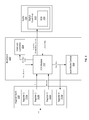
- FIG. 2 is a diagram of another example transceiver.
- FIG. 3A is a diagram of an example channel assessment process.
- FIG. 3B is a diagram of another example channel assessment process.
- FIG. 4 is a flow chart of an example process for assessing a communication channel.
- An electronic device may include a wireless transceiver that enables the device to communicate with other electronic devices.
- devices such as computers, tablet computers, cellular phones, access points, routers, and peripherals often include one or more wireless transceivers to transmit and receive data from other devices.
- multiple transceivers can operate in the same environment, and potentially can transmit and receive data using one or more of the same communication channels.
- transceivers first can determine if a communication channel is being used by another device before proceeding with data transmission.
- this can increase the efficiency by which multiple transceivers utilize a limited number of communication channels, and can increase the reliability of each communication.
- a transceiver with configurable channel assessment functionality can be used to assess one or more different communication channels under a variety of different operating conditions.
- the transceiver 100 includes a register bank 110 , a baseband 120 and a radio 130 .
- the register bank 110 , baseband 120 , and radio 130 are operatively coupled such that each of the components can communicate with each other (e.g., to exchange data and instructions between them).
- the register bank 110 stores data that can be retrieved by the other components of the transceiver 100 .
- the register bank 110 includes one or more registers, each of which can be used to store a particular portion of data. Data stored in the register bank 110 can be retrieved by the other components of the transceiver 100 .
- the register bank 110 can store parameters that define various aspects of the operation of the transceiver 100 , and these parameters can be retrieved by the baseband 120 or the radio 130 during operation of the transceiver 100 . Data also can be stored on the register bank 110 by the components of the transceiver 100 .
- the baseband 120 or the radio 130 can use the register bank 110 to store various pieces of data, such as data describing the status of each of the components, the outcome of one or more operations performed by the components, and so forth.
- the baseband 120 manages the functionality of the transceiver 100 .
- the baseband 120 can retrieve information from the register bank 110 , and manage the operation of the radio 130 based on the retrieved information.
- the baseband 120 can manage the modulation of information prior to transmission by the radio 130 , the demodulation of radio signals received by the radio 130 , or other aspects of the encoding and decoding data.
- the baseband 120 can manage the operation of the radio 130 , for instance to instruct the radio 130 to switch between an active or inactive state, or to transmit data and receive data in a particular manner (e.g., at a particular frequency or range of frequencies, at a particular transmission power, and so forth).
- the radio 130 transmits information by generating radiation of electromagnetic signals, and receives information by measuring radiation of electromagnetic signals.
- the radio 130 can generate a radio frequency alternating current based on information received from the baseband 120 , and apply the alternating current to a suitable conductor (e.g., an antenna). When excited by this alternating current, the antenna radiates radio waves, thereby broadcasting the information into the surrounding environment.
- the radio 130 can measure radiating radio waves that are incident upon the conductor, and transmit the measurements to the baseband 120 for analysis.
- the transceiver 100 can transmit information according to one or more communications standards.
- a communications standard establishes uniform engineering and/or technical criteria, processes, and practices for communicating in a particular manner.
- Example standards include IEEE 802.15.4g, ETSI TS 102 887, IEEE 802.15.4-2003, IEEE 802.15.4-2006, and IEEE 802.15.4-2011, among others.
- a communications standard can specify one or more physical layers each of which defines, at a bit-level, the particular mechanism by which data is transmitted between different devices.
- a physical layer can include, for instance, specification of particular electronic or mechanical interfaces connecting to the physical medium for synchronized communication.
- a physical layer also can include, for instance, specification of particular modulation techniques, signal multiplexing techniques, and error correction techniques to facilitate the transmission of data across the physical medium.
- Example physical layers include frequency-shift keying (FSK), orthogonal frequency-division multiplexing (OFPM), and offset quadrature phase-shift keying (OQPSK), among others.
- a communications standard also can define particular communication channels that are available for data transmission.
- a communication channel can be, for example a specific radio frequency or range of radio frequencies at which information can be transmitted and received.
- a communications standard can specify a broad range of frequencies that are available for data transmission, and specify individual frequency bands within that range that are allocated to particular channels.
- a communications standard also can specify particular location-specific protocols, operating parameters, or restrictions.
- a communications standard can specify a limit to maximum transmission power in accordance with regional regulations. These regions can be defined, for example, based on geographical location (e.g., country, county, or municipality of operation).
- each transceiver 100 can be operating in the same environment, and potentially can be transmitting and receiving data using one or more of the same communication channels.
- each transceiver 100 first can determine if a communication channel is being used another transceiver 100 before proceeding with data transmission. If the transceiver 100 determines that the communication channel is in use (e.g., “busy”), the transceiver 100 delays data transmission until the communication channel is determined to be available for use (e.g., “clear”). This assessment can be performed, for example, by the baseband 120 and the radio 130 .
- a transceiver 100 can determine if a communication channel is in use based on one or more assessment criteria. For example, a transceiver 100 can determine the amount of energy currently being transmitted through a communication channel (e.g., by measuring the amount of energy being transmitted over the channel, averaged over a particular interval of time). If the energy transmitted through the communication channel exceeds a particular threshold amount (e.g., if the average energy over the interval of time exceeds a threshold average amount), the transceiver 100 determines that the communication channel is busy. If not, the transceiver 100 determines that the communication channel is clear.
- a particular threshold amount e.g., if the average energy over the interval of time exceeds a threshold average amount
- a transceiver 100 can determine if recognizable data can be retrieved from the communication channel (e.g., a valid frame of data or a modulated signal). If so, the transceiver 100 determines that the communication channel is busy. If not, the transceiver 100 determines that the communication channel is clear.
- the communication channel e.g., a valid frame of data or a modulated signal
- a particular threshold amount of energy and interval of time might be used for one communications standard, and a different threshold amount of energy and/or interval of time might be used for another communications standard.
- a single communications standard might define different criteria for each of several physical layers and/or localities. For instance, a particular threshold amount of energy and interval of time might be used for one physical layer, and another threshold amount of energy and/or interval of time might be used for another physical layer.
- some communication standards define the interval of time and the threshold amount of energy relative to a certain physical layer characteristic. This can leads to different absolute settings. For example, in some cases, the interval of time may depend on the number of physical layer symbols and the absolute symbol length depend on the physical layer and/or data rate.
- a transceiver is capable of transmitting and receiving data according to multiple different communications standards, using multiple different physical layers, and/or within different geographical regions. As such, the transceiver should consider the appropriate assessment criteria in determining if a particular communication channel is in use.
- the transceiver 200 includes a register bank 210 , a baseband 220 , and a radio 230 . As with the transceiver 100 shown in FIG. 1 , the register bank 210 , and baseband 220 and the radio 230 of transceiver 200 are operatively coupled such that each of the components can communicate with each other (e.g., to exchange data and instructions between them).
- the register bank 210 can be similar to the register bank 110 shown in FIG. 1 .
- the register bank 210 stores data that can be retrieved by the other components of the transceiver 200 .
- the register bank 210 stores data in registers 212 a - d , each of which stores a particular amount of data. Data stored in the registers 212 a - d can be retrieved by the other components of the transceiver 200 .
- the registers 212 a - d can include parameters that define various aspects of the operation of the transceiver 200 , and can be retrieved by the baseband 220 or the radio 230 during operation of the transceiver 100 . As shown in FIG.
- the register 212 a stores data indicating when a communication channel should be assessed.
- the data contained within the register 212 a can be modified in order to trigger a channel assessment procedure.
- the register 212 b stores data indicating a particular time interval
- the register 212 c stores data indicating a particular threshold amount of energy.
- the data contained with the registers 212 b - c can be modified in order to specify different channel assessment parameters for use with a channel assessment procedure.
- the register 212 d stores data indicating if the communication channel is busy or clear.
- the data contained within the register 212 d can be modified based on the results of a channel assessment procedure, and can be retrieved by one or more other devices.
- Data can be transmitted to and from each of the registers 212 a - d through an appropriate communications interface, for example a serial peripheral interface (SPI) bus.
- SPI serial peripheral interface
- some or all of the data stored within the registers 212 a - d is user-selectable.
- the data stored within the registers 212 a - d can be selected and stored, at least in part, based on user input.
- the baseband 220 can be similar to the baseband 120 shown in FIG. 1 .
- the baseband 220 retrieves information from the register bank 210 , and manages the operation of the radio 230 based on the retrieved information. This can include, for example, managing the modulation of information prior to transmission by the radio 230 , the demodulation of radio signals received by the radio 230 , or other aspects of the encoding and decoding data.
- This also can include managing the operation of the radio 230 , for instance to instruct the radio 230 to switch between an active or inactive state, or to transmit data and receive data in a particular manner (e.g., at a particular frequency or range of frequencies, at a particular transmission power, and so forth). As described above, this also can include determining if a communication channel is being used by another transceiver, and adjusting the operation of the radio 230 accordingly.
- the radio 230 can be similar to the radio 130 shown in FIG. 1 .
- the radio 230 transmits information by generating radiation of electromagnetic signals, and receives information by measuring radiation of electromagnetic signals. This can include, for example, generating a radio frequency alternating current based on information received from the baseband 220 , and applying the alternating current to an antenna. This also can include, for example, measuring radiating radio waves that are incident upon the antenna, and transmitting the measurements to the baseband 220 for analysis.
- a transceiver first can determine if a communication channel is being used by another transceiver before proceeding with data transmission. If the transceiver determines that the communication channel is busy, the transceiver delays data transmission until the communication channel is determined to be clear. This assessment can be performed, for example, by the configurable clear channel assessment (CCA) module 222 of the baseband 220 .
- CCA configurable clear channel assessment
- the CCA module 222 receives signal measurements from a particular communication channel and a set of criteria for assessing that channel. Based on this information, the CCA module 222 determines the state of the communication channel (e.g., if the channel is busy or clear), and reports the state of the communication channel to one or more other components of the transceiver 200 . By using different sets of assessment criteria, the CCA module 222 can determine the status of a communication channel according to any one of several combinations of communications standards, physical layers, geographical locations, or other factors. Thus, the CCA module 222 provides configurable channel assessment functionality for the transceiver 200 .
- the CCA module 222 is operatively coupled to the register bank 210 (e.g., to each of the registers 212 a - d ), such that the CCA module 222 can retrieve data stored within the register bank 210 .
- the CCA module 222 also is coupled operatively to the radio 230 , such that it can manage the operation of the radio 230 and retrieve signal measurements obtained by the radio 230 .
- the CCA module 222 also is coupled operatively to an interrupt controller 224 , such that it can transmit interrupt signals to control or otherwise modify the operation of the transceiver 200 .
- the CCA module 222 retrieves the data stored in one or more of the registers 212 a - c . For instance, the CCA module 222 retrieves the data stored in register 212 a and, based on this data, determines whether or not to begin assessing a communication channel.
- the register 212 a can store a particular value indicating that the channel should be assessed (e.g., a value of “1”), or another value indicating that the channel should be not assessed (e.g., a value of “0”).
- the CCA module 222 can poll the contents of the register 212 a (e.g., continuously, intermittently, or arbitrarily retrieving the contents of the register 212 a ) in order to determine when to begin assessing the communication channel.
- the contents of the register 212 a can be modified through the SPI bus, for example in response to a command from another component of the transceiver 200 or another device altogether.
- the CCA module 222 can begin assessing a communication channel automatically before the transceiver 200 attempts to send data across a communication channel.
- the baseband 220 can include an automatic mode control module ( 226 ) that determines if the transceiver 200 is attempting to transmit data. Before the data is transmitted, the automatic mode control module 226 initiates a channel assessment (e.g., by modifying the contents of the register bank 210 , or by transmitting a command directly to the CCA module 222 ).
- the CCA module 222 When the CCA module 222 receives an indication to begin assessing the communication channel, it retrieves the data store in the registers 212 b - c .
- the registers 212 b - c each contain an assessment criterion to be used during the assessment of the communication channel.
- the register 212 b stores data that indicates a particular time interval for which the communication channel should be measured (t meas ), and the register 212 c stores data that indicates a particular threshold amount of energy (Threshold) that should be used in assessing the state of the communication channel.
- the contents of the registers 212 b - c also can be modified through an SPI bus, for example in response to a command from another component of the transceiver 200 or another device altogether.
- the CCA module 222 instructs the radio 230 to obtain energy measurements for the time interval (t meas ). For example, the CCA module 222 can transmit a command to the radio 230 to begin energy measurements, then transmit an command to the radio 230 to end energy measurements after the time interval (t meas ) has elapsed. In some cases, this command can be transmitted to a digital front end (DFE) 232 of the radio 230 .
- the DFE 232 can include, for example, one or more filters, low-noise amplifiers (LNAs), down-conversion mixers, and other components needed to process the modulated signals received at an antenna into signals suitable for input into baseband 220 .
- the radio 230 Upon receiving instructions from the CCA module 222 to begin energy measurements, the radio 230 obtains one or more measurements samples from the communication channel. As an example, the radio 230 can determine the amount of energy incident upon antenna at the frequency (or band of frequencies) corresponding to the communication channel. In some cases, the amount of energy is measured can be measured by the DFE using an automatic gain control (AGC) module.
- AGC automatic gain control
- the radio 230 Based on the amount of energy that is detected for a given time period (e.g., a pre-determined sample period), the radio 230 calculates a metric that represents the detected amount of energy. For example, the radio 230 can detect the amount of energy during a particular sample period, and calculate a received signal strength indication (RSSI) metric that indicates the amount of energy that was detected at that frequency range and for that sample period. This metric then is forwarded to the CCA module 222 . Sampling and metric calculation can be performed, for example, by an RSSI module 234 of the radio 230 . The radio 230 can repeat obtaining energy measurement samples and transmitting these measurement samples to the CCA module 222 until it receives a command to end energy measurement (e.g., until the time interval (t meas ) elapses).
- RSSI received signal strength indication
- the CCA module 222 calculates the average energy of the communication channel. This can be performed, for example, by averaging the metrics for each of the samples received from the radio 230 . After calculating the average energy, the CCA module 222 compares the average energy against the threshold amount of energy (Threshold). If the average energy exceeds the threshold energy (Threshold), the CCA module determines that the communication channel is in use by another device (e.g., “busy”). If the average energy does not exceed the threshold energy (Threshold), the CCA module 222 determines that the communication channel is not in use by another device (e.g., “clear”) and is available for use by the transceiver 200 .
- the threshold amount of energy e.g., “busy”
- the CCA module 222 determines that the communication channel is not in use by another device (e.g., “clear”) and is available for use by the transceiver 200 .
- the CCA module 222 transmits data indicating the state of the communication channel to the register 212 d , where it can be retrieved by the other components of the transceiver 200 or by another device altogether. In some implementations, the CCA module 222 also transmits data indicating the state of the communication channel to the automatic mode control module 226 . In response, the automatic module control module 226 either can initiate data transmission across the communication channel (e.g., when the communication channel is “clear”), or prevent data from being transmitted across the communication by the transceiver 200 at least until the communication channel is clear (e.g., when the communication channel is “busy”).
- the CCA module 222 can use a single energy measurement from a single measurement sample. For example, the CCA module 222 can instruct the radio 230 to obtain a single measurement sample, and compare the metric from the single measurement sample against the threshold energy (Threshold). This can be beneficial in some circumstances, for example if it is desirable to assess a communication channel quickly.
- the CCA module 222 also can control or otherwise modify the operation of the transceiver 200 based on the status of the communication channel. For example, the CCA module 222 can send one or more interrupt signals to the interrupt controller 224 . Based on the received interrupt signals, the interrupt controller 224 can modify the operation of the transceiver 200 . For example, upon determining that the communication channel is in use by other device, the CCA module 222 can transmit an interrupt signals to the interrupt controller 224 , indicating that the transmission of data to the communication channel should be prevented, interrupted, or otherwise delayed until the communication channel is ready for use. As another example, upon determining that the communication is not in use by another device, the CCA module 222 can transmit an interrupt signals to the interrupt controller 224 , indicating that the transmission of data can proceed.
- the CCA module 222 can assess a communication channel continuously, periodically, or arbitrarily (e.g., in response to a command by a user, another component of the transceiver 200 , or another device altogether). In some cases, the CCA module 222 can assess a communication channel, and based on the result of the assessment, either continue or discontinue assessment. As an example, referring to FIG. 3A , a CCA module 222 assesses the status of a communication channel (time interval 302 ). Upon determining that the communication channel is clear (event 304 ), the CCA module 222 reports that the communication channel is clear, and the transceiver 200 proceeds transmitting data (time interval 306 ).
- a CCA module 222 assesses the status of a communication channel (time interval 320 ). Upon determining that the communication channel is busy (event 322 ), the CCA module 222 reports that the communication channel is clear and “backs off” for a particular amount of time (time interval 324 ). This “back off” time period can vary, depending on the implementation. For example, in some cases the back off time period can be pre-determined (e.g., a value that is specified by a user, by the transceiver 200 , or by another device altogether). In some cases, the back off time period can be defined according to a communications standard.
- the CCA module 222 again assesses the status of the communication channel (time interval 326 ). Upon determining that the communication channel is clear (event 328 ), the CCA module 222 reports that the communication channel is clear, and the transceiver 200 proceeds transmitting data (time interval 330 ). In this manner, the CCA module 222 can assess a communication channel, and if the communication channel is busy, prevent the transceiver 200 from transmitting data and repeat the assessment periodically until the communication channel is no longer busy.
- the CCA module 222 can repeat channel assessment any number of times.
- the repetition of channel assessment can be limited to a particular number (e.g., in order to prevent the transceiver 200 from endlessly assessing a channel).
- the repetition of channel assessment is not limited to a particular number, and can repeat until the communication channel is clear or until the process is manually interrupted.
- a transceiver can transmit and receive data according to multiple different communications standards, using multiple different physical layers, and/or within different geographical regions.
- the transceiver should be configured to consider the appropriate assessment criteria in determining if a particular communication channel is in use. This can be achieved using the register bank 210 .
- the register 212 b stores data indicating a particular time interval (t meas ) in which the energy of a communication channel should be measured
- the register 212 c stores data indicating a particular threshold amount of energy (Threshold) that is used to determine if the communication channel is busy or clear.
- the contents of the registers 212 b and 212 c can be modified depending on the particular operating conditions of the transceiver. For example, if a particular communications standard and physical layer are being used in a particular location, data reflecting the appropriate time interval (t meas ) and threshold amount of energy (Threshold) are stored in the registers 212 b and 212 c , respectively. If another communications standard or physical layer are used, the contents of the registers 212 b and 212 c can be modified as necessary (e.g., through the SPI bus).
- the CCA module 222 is not limited to any one set of assessment parameters, and can perform channel assessment according to assessment parameters specific to any combination of communications standards, physical layers, and/or geographical locations.
- the contents of the register bank 210 can be modified by another component of the transceiver 200 (e.g., by a data processing apparatus) to suit the circumstances under which the transceiver 200 operates.
- a data processing apparatus can obtain information regarding the current communications standard, physical layer, and/or geographical location of the transceiver 200 . Based on this information, the data processing apparatus can determine an appropriate set of assessment parameters, and modify the contents of the register bank 210 as needed. In some cases, the data processing apparatus can modify the contents of the register bank 210 automatically or semi-automatically, such that no user input is required. Accordingly, once the CCA module 222 retrieves the contents of the register bank 210 , the CCA module 222 will perform channel assessment according to appropriate parameters.
- the contents of the register bank 210 can be modified based, at least in part, on user input.
- the contents of the register bank 210 can reflect a user selection (e.g., a user selection of a particular communication standard, physical layer, and/or graphical location, or a user selection of specific assessment parameters).
- the contents of the register bank 210 can be subsequently modified based, at least in part, on additional user input.
- the contents of the register bank 210 can be subsequently modified to reflect a different user selection (e.g., a user selection of a different communication standard, physical layer, and/or graphical location, or a user selection of different specific assessment parameters). This can be performed, for example, by replacing, overwriting, or otherwise modifying the contents of the register bank 210 .
- the contents of the register bank 210 can be modified “on the fly,” such that the assessment parameters can be stored and/or modified before, during, and/or after the performance of each channel assessment.
- the register bank 210 can store a first set of assessment parameters (e.g., a first set of user selected parameters), and the transceiver 200 can perform one or more channel assessments according to the first set of assessment parameters.
- the register bank 210 can store a second set of assessment parameters (e.g., a second set of user selected parameters), and the transceiver 200 can perform one or more channel assessments according to the second set of assessment parameters.
- the transceiver 200 need not operate according to a pre-defined set of assessment parameters (e.g., assessment parameters that were pre-defined during the initial manufacturing process), and can instead by re-configured by a user as needed prior to each use.
- a user can select certain assessment parameters based on the expected operating context of the transceiver 200 (e.g., based on an expected communication standard, physical layer, and/or location). If the operating context later changes (e.g., if the communication standard, physical layer, and/or location later changes), the user can select new assessment parameters based on the new operating context.
- the specific values of each of the assessment parameters can vary, depending on the implementation.
- the time interval (t meas ) can be selected from among a pool of time interval values, where each time interval value in the pool corresponds to one or more particular combinations of factors (e.g., combinations of communications standard, physical layer, and/or geographical location).
- the time interval values in the pool can include 2 ⁇ s, 8 ⁇ s, 32 ⁇ s, 128 ⁇ s, 512 ⁇ s, and/or any other interval of time.
- the time interval values in the pool can be selected based on the sampling rate of the radio 230 (e.g., the sampling rate of the DFE 232 ).
- the threshold amount of energy can be selected from among a pool of energy values, where each time energy value in the pool corresponds to one or more particular combinations of factors (e.g., one or more combinations of communications standard, physical layer, and/or geographical location).
- the energy values in the pool can be expressed as an RSSI value with arbitrary units.
- the energy values in the pool can be scaled according to an arbitrary range (e.g., between 0 and 127), and each energy value can be a value within that range (e.g., 1, 10, 20, 30, 40, 50 and/or any other value).
- the energy values in the pool can be expressed as a ratio between a power measurement and a reference amount of power.
- the energy values in the pool can be expressed in Decibel-milliwatts (dBm), and can include ⁇ 6 dBm, ⁇ 3 dBm, ⁇ 1 dBm, 0, dBm, 1 dBm, 3 dBm, 6 dBm, or any other value.
- transceivers are shown in FIG. 1 and FIG. 2 , these are simplified examples to illustrate the concept of configurable channel assessment.
- a transceiver can include other components, either in addition to or instead of those described above.
- FIG. 2 shows components of the transceiver 200 in connection with configurable channel assessment functionality, the transceiver 200 can include additional components related to the above described functionality or other aspects of the transceiver 200 .
- FIG. 4 An example process 400 for assessing a communication channel is shown in FIG. 4 .
- the process 400 can be performed, for example, either partially or entirely by a transceiver 200 .
- the process 400 can be initiated in various ways. For example, in some case, the process 400 is initiated when data is written to a register (e.g., the register 212 a shown in FIG. 2 ) indicating that a channel assessment procedure should begin.
- a register e.g., the register 212 a shown in FIG. 2
- the process 400 begins by receiving a set of assessment parameters (step 410 ).
- the set of assessment parameters can include data that is indicative of a time interval and an energy threshold.
- these assessment parameters can include the time interval (t meas ) and the threshold amount of energy (Threshold) described above.
- the set of assessment parameters can be stored in a register bank (e.g., the register bank 210 ), and retrieved by a baseband (e.g., the base band 220 ).
- the set of parameters can correspond to a particular communications standard.
- one or more of the assessment parameters can be selected from among a plurality of values.
- a time interval can be selected from among a plurality of different time intervals, each corresponding to a particular combination of communications standard, physical layer, and/or locality.
- a threshold amount of energy can be selected from among a plurality of different threshold amounts of energy, each also corresponding to a particular combination of communications standard, physical layer, and/or locality.
- an appropriate set of assessment parameters is selected based on the specific operating conditions of a device.
- the set of assessment parameters can be user-selected.
- the set of assessment parameter can be based, at least in part, on user specified information (e.g., a user selection of a particular communication standard, physical layer, and/or graphical location, or a user selection of specific assessment parameters).
- the process 400 continues by comparing the average energy of a communication channel to the threshold (step 420 ). As described above, this comparison can include receiving one or more energy samples from the communication channel during the time interval, and determining the average energy of the communication channel based on the energy samples. This average energy can then be compared to the energy threshold.
- the process 400 continues to determine if the average energy exceeds the threshold (step 430 ). If so, it is determined that the communication channel is busy (step 440 ). In some implementations, upon determining that the communication channel is busy, the transmission of data over the communication channel can be prevented, interrupted, or delayed until the communication channel is clear.
- step 450 If the average energy does not exceed the threshold, it is determined that the communication channel is available for transmission (step 450 ). In some implementations, upon determining that the communication channel is available for transmission, data is transmitted over the communication channel.
- process 400 can be repeated, either in in part or as a whole, in order to assess a second communication channel. For instance, one or more of the steps 410 , 420 , 430 , 440 , and 450 can be repeated for a second communication channel.
- a second set of assessment parameters can be received, where the second set of assessment parameters includes a second time interval and a second energy threshold value different than the first time interval and the first energy threshold value.
- the second set of assessment parameters also can be user-selected.
- the second set of assessment parameter can be based, at least in part, on user specified information (e.g., a user selection of a particular communication standard, physical layer, and/or graphical location, or a user selection of specific assessment parameters).
- the average energy of the second communication channel is compared to the second energy threshold value. If the average energy of the second communication channel exceeds the second threshold, it is determined that the communication channel is busy. In a similar manner as described above, upon determining that the second communication channel is busy, the transmission of data over the second communication channel can be prevented, interrupted, or delayed until the second communication channel is clear. If the average energy of the second communication channel does not exceed the second threshold, it is determined that the communication channel is available for transmission. In a similar manner as described above, upon determining that the second communication channel is available for transmission, data can be transmitted over the second communication channel.
- the first communication channel and the second communication channel are the same communication channel, and that communication channel can be assessed according to different sets of assessment parameters.
- the first communication channel and the second communication channel are different communication channels, and the communication channels can each be assessed according to different sets of assessment parameters.
- any number of communication channels can be assessed based on criteria corresponding to any number of different communications standards, physical layers, and/or locations.
- the process 400 can be performed in order to assess communication channels in a broad range of operating conditions.
- registers are used to store data such as assessment parameters, indications to initiate channel assessment, and so forth.
- data can be stored using one or more other data storage devices, such as memory modules.
- data e.g., assessment parameters and/or indications to initiate channel assessment
- the baseband 120 e.g., the CCA module 222
- the baseband 120 can retrieve this data from the appropriate locations of the memory modules.
- SPI buses to modify the contents of a register
- other mechanisms can be used to modify the contents of a register and/or memory module, as appropriate for the implementation.
- determining if a communication channel is being used by other devices before proceeding with a data transmission can increase the efficiency by which multiple devices utilize a limited number of communication channels, and can increase the reliability of each communication.
- a transceiver can provide configurable channel assessment functionality, a transceiver can determine if a communication channel is in use under a variety of different operating conditions. Thus, it is not necessary to design and manufacture different transceivers to suit each unique combination of operating conditions. Rather, a single configurable transceiver can be used in several different contexts.
- the transceiver need not be replaced, but instead can be re-configured as needed.
- Some implementations of subject matter and operations described in this specification can be implemented in digital electronic circuitry, or in computer software, firmware, or hardware, including the structures disclosed in this specification and their structural equivalents, or in combinations of one or more of them.
- the registers 110 and 210 , the basebands 120 and 220 , and the radios 130 and 230 can be implemented using digital electronic circuitry, or in computer software, firmware, or hardware, or in combinations of one or more of them.
- the process 400 can be implemented using digital electronic circuitry, or in computer software, firmware, or hardware, or in combinations of one or more of them.
- Some implementations described in this specification can be implemented as one or more groups or modules of digital electronic circuitry, computer software, firmware, or hardware, or in combinations of one or more of them. Although different modules can be used, each module need not be distinct, and multiple modules can be implemented on the same digital electronic circuitry, computer software, firmware, or hardware, or combination thereof.
- Some implementations described in this specification can be implemented as one or more computer programs, i.e., one or more modules of computer program instructions, encoded on computer storage medium for execution by, or to control the operation of, data processing apparatus.
- a computer storage medium can be, or can be included in, a computer-readable storage device, a computer-readable storage substrate, a random or serial access memory array or device, or a combination of one or more of them.
- a computer storage medium is not a propagated signal
- a computer storage medium can be a source or destination of computer program instructions encoded in an artificially generated propagated signal.
- the computer storage medium can also be, or be included in, one or more separate physical components or media (e.g., multiple CDs, disks, or other storage devices).
- the term “data processing apparatus” encompasses all kinds of apparatus, devices, and machines for processing data, including by way of example a programmable processor, a computer, a system on a chip, or multiple ones, or combinations, of the foregoing.
- the apparatus can include special purpose logic circuitry, e.g., an FPGA (field programmable gate array) or an ASIC (application specific integrated circuit).
- the apparatus can also include, in addition to hardware, code that creates an execution environment for the computer program in question, e.g., code that constitutes processor firmware, a protocol stack, a database management system, an operating system, a cross-platform runtime environment, a virtual machine, or a combination of one or more of them.
- the apparatus and execution environment can realize various different computing model infrastructures, such as web services, distributed computing and grid computing infrastructures.
- a computer program (also known as a program, software, software application, script, or code) can be written in any form of programming language, including compiled or interpreted languages, declarative or procedural languages.
- a computer program may, but need not, correspond to a file in a file system.
- a program can be stored in a portion of a file that holds other programs or data (e.g., one or more scripts stored in a markup language document), in a single file dedicated to the program in question, or in multiple coordinated files (e.g., files that store one or more modules, sub programs, or portions of code).
- a computer program can be deployed to be executed on one computer or on multiple computers that are located at one site or distributed across multiple sites and interconnected by a communication network.
- Some of the processes and logic flows described in this specification can be performed by one or more programmable processors executing one or more computer programs to perform actions by operating on input data and generating output.
- the processes and logic flows can also be performed by, and apparatus can also be implemented as, special purpose logic circuitry, e.g., an FPGA (field programmable gate array) or an ASIC (application specific integrated circuit).
- processors suitable for the execution of a computer program include, by way of example, both general and special purpose microprocessors, and processors of any kind of digital computer.
- a processor will receive instructions and data from a read only memory or a random access memory or both.
- a computer includes a processor for performing actions in accordance with instructions and one or more memory devices for storing instructions and data.
- a computer may also include, or be operatively coupled to receive data from or transfer data to, or both, one or more mass storage devices for storing data, e.g., magnetic, magneto optical disks, or optical disks.
- mass storage devices for storing data, e.g., magnetic, magneto optical disks, or optical disks.
- a computer need not have such devices.
- Devices suitable for storing computer program instructions and data include all forms of non-volatile memory, media and memory devices, including by way of example semiconductor memory devices (e.g., EPROM, EEPROM, flash memory devices, and others), magnetic disks (e.g., internal hard disks, removable disks, and others), magneto optical disks, and CD ROM and DVD-ROM disks.
- semiconductor memory devices e.g., EPROM, EEPROM, flash memory devices, and others
- magnetic disks e.g., internal hard disks, removable disks, and others
- magneto optical disks e.g., CD ROM and DVD-ROM disks.
- the processor and the memory can be supplemented by, or incorporated in, special purpose logic circuitry.
- a computer having a display device (e.g., a monitor, or another type of display device) for displaying information to the user and a keyboard and a pointing device (e.g., a mouse, a trackball, a tablet, a touch sensitive screen, or another type of pointing device) by which the user can provide input to the computer.
- a display device e.g., a monitor, or another type of display device
- a keyboard and a pointing device e.g., a mouse, a trackball, a tablet, a touch sensitive screen, or another type of pointing device
- Other kinds of devices can be used to provide for interaction with a user as well; for example, feedback provided to the user can be any form of sensory feedback, e.g., visual feedback, auditory feedback, or tactile feedback; and input from the user can be received in any form, including acoustic, speech, or tactile input.
- a computer can interact with a user by sending documents to and receiving documents from a device that is used
- a computer system may include a single computing device, or multiple computers that operate in proximity or generally remote from each other and typically interact through a communication network.
- Examples of communication networks include a local area network (“LAN”) and a wide area network (“WAN”), an inter-network (e.g., the Internet), a network comprising a satellite link, and peer-to-peer networks (e.g., ad hoc peer-to-peer networks).
- LAN local area network
- WAN wide area network
- Internet inter-network
- peer-to-peer networks e.g., ad hoc peer-to-peer networks.
- a relationship of client and server may arise by virtue of computer programs running on the respective computers and having a client-server relationship to each other.
Landscapes
- Engineering & Computer Science (AREA)
- Computer Networks & Wireless Communication (AREA)
- Signal Processing (AREA)
- Mobile Radio Communication Systems (AREA)
Abstract
Description
Claims (23)
Priority Applications (2)
| Application Number | Priority Date | Filing Date | Title |
|---|---|---|---|
| US14/532,209 US9560673B2 (en) | 2014-11-04 | 2014-11-04 | Configurable clear channel assessment |
| DE102015221473.7A DE102015221473A1 (en) | 2014-11-04 | 2015-11-03 | Configurable evaluation of free channels |
Applications Claiming Priority (1)
| Application Number | Priority Date | Filing Date | Title |
|---|---|---|---|
| US14/532,209 US9560673B2 (en) | 2014-11-04 | 2014-11-04 | Configurable clear channel assessment |
Publications (2)
| Publication Number | Publication Date |
|---|---|
| US20160128070A1 US20160128070A1 (en) | 2016-05-05 |
| US9560673B2 true US9560673B2 (en) | 2017-01-31 |
Family
ID=55753336
Family Applications (1)
| Application Number | Title | Priority Date | Filing Date |
|---|---|---|---|
| US14/532,209 Active 2035-02-19 US9560673B2 (en) | 2014-11-04 | 2014-11-04 | Configurable clear channel assessment |
Country Status (2)
| Country | Link |
|---|---|
| US (1) | US9560673B2 (en) |
| DE (1) | DE102015221473A1 (en) |
Families Citing this family (6)
| Publication number | Priority date | Publication date | Assignee | Title |
|---|---|---|---|---|
| KR102080982B1 (en) * | 2015-02-06 | 2020-02-24 | 애플 인크. | Method and apparatus for time division LTE transmission in unlicensed radio frequency band |
| US10757734B2 (en) * | 2016-07-11 | 2020-08-25 | Telefonaktiebolaget Lm Ericsson (Publ) | Method for facilitating clear channel assessment and radio unit |
| CN112740739B (en) * | 2018-11-20 | 2022-10-21 | 深圳市欢太科技有限公司 | Interference processing method and device, storage medium and electronic equipment |
| US10616005B1 (en) * | 2018-11-28 | 2020-04-07 | Samsung Electronics Co., Ltd. | Robust noise power estimation |
| WO2020109648A1 (en) * | 2018-11-30 | 2020-06-04 | Nokia Technologies Oy | Channel contention and resource management in wireless network |
| US11917040B1 (en) * | 2022-03-30 | 2024-02-27 | Amazon Technologies, Inc. | Converting communication protocols for messages to enable internet access for vehicle applications |
Citations (4)
| Publication number | Priority date | Publication date | Assignee | Title |
|---|---|---|---|---|
| US20070286122A1 (en) * | 2006-06-12 | 2007-12-13 | Motorola, Inc. | Clear channel assessment threshold adaptation in a wireless network |
| US20120106496A1 (en) * | 2009-07-03 | 2012-05-03 | Canon Kabushiki Kaisha | Communication apparatus, communication apparatus control method, and program |
| US20120106529A1 (en) | 2010-11-03 | 2012-05-03 | Tilo Ferchland | Transmitting Data Between Nodes of a Wireless Network |
| US8705670B2 (en) | 2010-08-16 | 2014-04-22 | Atmel Corporation | Receiver and method for the reception of a node by a receiver in a wireless network |
-
2014
- 2014-11-04 US US14/532,209 patent/US9560673B2/en active Active
-
2015
- 2015-11-03 DE DE102015221473.7A patent/DE102015221473A1/en active Pending
Patent Citations (4)
| Publication number | Priority date | Publication date | Assignee | Title |
|---|---|---|---|---|
| US20070286122A1 (en) * | 2006-06-12 | 2007-12-13 | Motorola, Inc. | Clear channel assessment threshold adaptation in a wireless network |
| US20120106496A1 (en) * | 2009-07-03 | 2012-05-03 | Canon Kabushiki Kaisha | Communication apparatus, communication apparatus control method, and program |
| US8705670B2 (en) | 2010-08-16 | 2014-04-22 | Atmel Corporation | Receiver and method for the reception of a node by a receiver in a wireless network |
| US20120106529A1 (en) | 2010-11-03 | 2012-05-03 | Tilo Ferchland | Transmitting Data Between Nodes of a Wireless Network |
Non-Patent Citations (4)
| Title |
|---|
| AT86FR233, Low Power, 2.4GHz Transceiver for ZigBee, RF4CE, IEEE 802.16.4, 6LoWPAN, and ISM Aplications, Preliminary Datasheet, Atmel-8351E-MCU Wireless-AT86RF233 Datasheet, 232 pages (2014). |
| IEEE Standard for Local and Metropolitan Area Networks, Part 15,4: Low-Rate Wireless Personal Area Networks (LR-WPANs), Amendment 3: Physical Layer (PHY) Specifications for Low-Data-Rate, Wireless, Smart Metering utility Networks; IEEE Std 802.15.4g(TM)-2012 (Amendment to IEEE Std 802.15.4(TM)-2011) IEEE Standards Association, 252 pages (Apr. 27, 2012). |
| IEEE Standard for Local and Metropolitan Area Networks, Part 15,4: Low-Rate Wireless Personal Area Networks (LR-WPANs), Amendment 3: Physical Layer (PHY) Specifications for Low-Data-Rate, Wireless, Smart Metering utility Networks; IEEE Std 802.15.4g™-2012 (Amendment to IEEE Std 802.15.4™-2011) IEEE Standards Association, 252 pages (Apr. 27, 2012). |
| Low Power, 700/800/900MHz Transceiver for ZigBee, IEEE 802.15.4, 6LoWAN, and ISM Applications, Atmel 42002C-MCU Wireless, 212 pages (2013). |
Also Published As
| Publication number | Publication date |
|---|---|
| US20160128070A1 (en) | 2016-05-05 |
| DE102015221473A1 (en) | 2016-05-04 |
Similar Documents
| Publication | Publication Date | Title |
|---|---|---|
| US9560673B2 (en) | Configurable clear channel assessment | |
| US11874388B2 (en) | Device-free subject localization methods and systems using wireless signals | |
| US10609537B2 (en) | Proximity platform | |
| TWI688300B (en) | Apparatuses and methods for a physical random access channel (prach) retransmission | |
| EP3008827B1 (en) | Radio frequency (rf) power back-off optimization for specific absorption rate (sar) compliance | |
| US20200336194A1 (en) | Joint beam reporting for wireless networks | |
| EP2923509B1 (en) | Wireless access point mapping | |
| TW201947892A (en) | UE and methods for beam selection during a physical random access channel (PRACH) transmission or retransmission | |
| JP2017506325A (en) | Apparatus, system and method for estimating position of mobile device | |
| JP6179170B2 (en) | Communications system | |
| AU2011216135A1 (en) | Distributed database access for spectrum access | |
| CN104113870B (en) | Network test method and mobile terminal | |
| CN114521012B (en) | Positioning method, positioning device, terminal equipment, base station and position management server | |
| EP3400681A1 (en) | Performance monitoring techniques for virtualized resources | |
| US20210328647A1 (en) | Location sensing method and apparatus, and positioning method and apparatus | |
| US20190379468A1 (en) | Techniques for channel state determination | |
| JP2018050125A (en) | Radio communication equipment, radio communication terminal and radio communication method | |
| TW201939991A (en) | Positioning method and system for communication network | |
| JP2013143765A (en) | Antenna array control method and access point using the same | |
| US20200178186A1 (en) | Access Method And Access Device | |
| CN114173282A (en) | Low energy beacon configuration by tapping beacons with another device | |
| WO2011087935A2 (en) | Method of controlling resource usage in communication systems | |
| US10834609B2 (en) | Optimal wireless router positioning | |
| Fortuna et al. | Software interfaces for control, optimization and update of 5G machine type communication networks | |
| JP6394750B2 (en) | Communications system |
Legal Events
| Date | Code | Title | Description |
|---|---|---|---|
| AS | Assignment |
Owner name: ATMEL AUTOMOTIVE GMBH, GERMANY Free format text: ASSIGNMENT OF ASSIGNORS INTEREST;ASSIGNORS:HANUSCH, THOMAS;WALTER, UDO;ZARBOCK, JEANNETTE;REEL/FRAME:034554/0430 Effective date: 20141104 |
|
| AS | Assignment |
Owner name: ATMEL CORPORATION, CALIFORNIA Free format text: ASSIGNMENT OF ASSIGNORS INTEREST;ASSIGNOR:ATMEL AUTOMOTIVE GMBH;REEL/FRAME:035461/0036 Effective date: 20141216 |
|
| AS | Assignment |
Owner name: MORGAN STANLEY SENIOR FUNDING, INC., AS ADMINISTRA Free format text: PATENT SECURITY AGREEMENT;ASSIGNOR:ATMEL CORPORATION;REEL/FRAME:035918/0451 Effective date: 20150513 |
|
| STCF | Information on status: patent grant |
Free format text: PATENTED CASE |
|
| AS | Assignment |
Owner name: JPMORGAN CHASE BANK, N.A., AS ADMINISTRATIVE AGENT, ILLINOIS Free format text: SECURITY INTEREST;ASSIGNOR:ATMEL CORPORATION;REEL/FRAME:041715/0747 Effective date: 20170208 Owner name: JPMORGAN CHASE BANK, N.A., AS ADMINISTRATIVE AGENT Free format text: SECURITY INTEREST;ASSIGNOR:ATMEL CORPORATION;REEL/FRAME:041715/0747 Effective date: 20170208 |
|
| AS | Assignment |
Owner name: JPMORGAN CHASE BANK, N.A., AS ADMINISTRATIVE AGENT, ILLINOIS Free format text: SECURITY INTEREST;ASSIGNORS:MICROCHIP TECHNOLOGY INCORPORATED;SILICON STORAGE TECHNOLOGY, INC.;ATMEL CORPORATION;AND OTHERS;REEL/FRAME:046426/0001 Effective date: 20180529 Owner name: JPMORGAN CHASE BANK, N.A., AS ADMINISTRATIVE AGENT Free format text: SECURITY INTEREST;ASSIGNORS:MICROCHIP TECHNOLOGY INCORPORATED;SILICON STORAGE TECHNOLOGY, INC.;ATMEL CORPORATION;AND OTHERS;REEL/FRAME:046426/0001 Effective date: 20180529 |
|
| AS | Assignment |
Owner name: WELLS FARGO BANK, NATIONAL ASSOCIATION, AS NOTES COLLATERAL AGENT, CALIFORNIA Free format text: SECURITY INTEREST;ASSIGNORS:MICROCHIP TECHNOLOGY INCORPORATED;SILICON STORAGE TECHNOLOGY, INC.;ATMEL CORPORATION;AND OTHERS;REEL/FRAME:047103/0206 Effective date: 20180914 Owner name: WELLS FARGO BANK, NATIONAL ASSOCIATION, AS NOTES C Free format text: SECURITY INTEREST;ASSIGNORS:MICROCHIP TECHNOLOGY INCORPORATED;SILICON STORAGE TECHNOLOGY, INC.;ATMEL CORPORATION;AND OTHERS;REEL/FRAME:047103/0206 Effective date: 20180914 |
|
| AS | Assignment |
Owner name: JPMORGAN CHASE BANK, N.A., AS ADMINISTRATIVE AGENT, DELAWARE Free format text: SECURITY INTEREST;ASSIGNORS:MICROCHIP TECHNOLOGY INC.;SILICON STORAGE TECHNOLOGY, INC.;ATMEL CORPORATION;AND OTHERS;REEL/FRAME:053311/0305 Effective date: 20200327 |
|
| AS | Assignment |
Owner name: MICROSEMI STORAGE SOLUTIONS, INC., ARIZONA Free format text: RELEASE BY SECURED PARTY;ASSIGNOR:JPMORGAN CHASE BANK, N.A, AS ADMINISTRATIVE AGENT;REEL/FRAME:053466/0011 Effective date: 20200529 Owner name: MICROSEMI CORPORATION, CALIFORNIA Free format text: RELEASE BY SECURED PARTY;ASSIGNOR:JPMORGAN CHASE BANK, N.A, AS ADMINISTRATIVE AGENT;REEL/FRAME:053466/0011 Effective date: 20200529 Owner name: ATMEL CORPORATION, ARIZONA Free format text: RELEASE BY SECURED PARTY;ASSIGNOR:JPMORGAN CHASE BANK, N.A, AS ADMINISTRATIVE AGENT;REEL/FRAME:053466/0011 Effective date: 20200529 Owner name: SILICON STORAGE TECHNOLOGY, INC., ARIZONA Free format text: RELEASE BY SECURED PARTY;ASSIGNOR:JPMORGAN CHASE BANK, N.A, AS ADMINISTRATIVE AGENT;REEL/FRAME:053466/0011 Effective date: 20200529 Owner name: MICROCHIP TECHNOLOGY INC., ARIZONA Free format text: RELEASE BY SECURED PARTY;ASSIGNOR:JPMORGAN CHASE BANK, N.A, AS ADMINISTRATIVE AGENT;REEL/FRAME:053466/0011 Effective date: 20200529 |
|
| AS | Assignment |
Owner name: WELLS FARGO BANK, NATIONAL ASSOCIATION, MINNESOTA Free format text: SECURITY INTEREST;ASSIGNORS:MICROCHIP TECHNOLOGY INC.;SILICON STORAGE TECHNOLOGY, INC.;ATMEL CORPORATION;AND OTHERS;REEL/FRAME:053468/0705 Effective date: 20200529 |
|
| MAFP | Maintenance fee payment |
Free format text: PAYMENT OF MAINTENANCE FEE, 4TH YEAR, LARGE ENTITY (ORIGINAL EVENT CODE: M1551); ENTITY STATUS OF PATENT OWNER: LARGE ENTITY Year of fee payment: 4 |
|
| AS | Assignment |
Owner name: WELLS FARGO BANK, NATIONAL ASSOCIATION, AS COLLATERAL AGENT, MINNESOTA Free format text: SECURITY INTEREST;ASSIGNORS:MICROCHIP TECHNOLOGY INCORPORATED;SILICON STORAGE TECHNOLOGY, INC.;ATMEL CORPORATION;AND OTHERS;REEL/FRAME:055671/0612 Effective date: 20201217 |
|
| AS | Assignment |
Owner name: WELLS FARGO BANK, NATIONAL ASSOCIATION, AS NOTES COLLATERAL AGENT, MINNESOTA Free format text: SECURITY INTEREST;ASSIGNORS:MICROCHIP TECHNOLOGY INCORPORATED;SILICON STORAGE TECHNOLOGY, INC.;ATMEL CORPORATION;AND OTHERS;REEL/FRAME:057935/0474 Effective date: 20210528 |
|
| AS | Assignment |
Owner name: MICROSEMI STORAGE SOLUTIONS, INC., ARIZONA Free format text: RELEASE BY SECURED PARTY;ASSIGNOR:JPMORGAN CHASE BANK, N.A., AS ADMINISTRATIVE AGENT;REEL/FRAME:059333/0222 Effective date: 20220218 Owner name: MICROSEMI CORPORATION, ARIZONA Free format text: RELEASE BY SECURED PARTY;ASSIGNOR:JPMORGAN CHASE BANK, N.A., AS ADMINISTRATIVE AGENT;REEL/FRAME:059333/0222 Effective date: 20220218 Owner name: ATMEL CORPORATION, ARIZONA Free format text: RELEASE BY SECURED PARTY;ASSIGNOR:JPMORGAN CHASE BANK, N.A., AS ADMINISTRATIVE AGENT;REEL/FRAME:059333/0222 Effective date: 20220218 Owner name: SILICON STORAGE TECHNOLOGY, INC., ARIZONA Free format text: RELEASE BY SECURED PARTY;ASSIGNOR:JPMORGAN CHASE BANK, N.A., AS ADMINISTRATIVE AGENT;REEL/FRAME:059333/0222 Effective date: 20220218 Owner name: MICROCHIP TECHNOLOGY INCORPORATED, ARIZONA Free format text: RELEASE BY SECURED PARTY;ASSIGNOR:JPMORGAN CHASE BANK, N.A., AS ADMINISTRATIVE AGENT;REEL/FRAME:059333/0222 Effective date: 20220218 |
|
| AS | Assignment |
Owner name: ATMEL CORPORATION, ARIZONA Free format text: RELEASE BY SECURED PARTY;ASSIGNOR:JPMORGAN CHASE BANK, N.A., AS ADMINISTRATIVE AGENT;REEL/FRAME:059262/0105 Effective date: 20220218 |
|
| AS | Assignment |
Owner name: MICROSEMI STORAGE SOLUTIONS, INC., ARIZONA Free format text: RELEASE BY SECURED PARTY;ASSIGNOR:WELLS FARGO BANK, NATIONAL ASSOCIATION, AS NOTES COLLATERAL AGENT;REEL/FRAME:059358/0001 Effective date: 20220228 Owner name: MICROSEMI CORPORATION, ARIZONA Free format text: RELEASE BY SECURED PARTY;ASSIGNOR:WELLS FARGO BANK, NATIONAL ASSOCIATION, AS NOTES COLLATERAL AGENT;REEL/FRAME:059358/0001 Effective date: 20220228 Owner name: ATMEL CORPORATION, ARIZONA Free format text: RELEASE BY SECURED PARTY;ASSIGNOR:WELLS FARGO BANK, NATIONAL ASSOCIATION, AS NOTES COLLATERAL AGENT;REEL/FRAME:059358/0001 Effective date: 20220228 Owner name: SILICON STORAGE TECHNOLOGY, INC., ARIZONA Free format text: RELEASE BY SECURED PARTY;ASSIGNOR:WELLS FARGO BANK, NATIONAL ASSOCIATION, AS NOTES COLLATERAL AGENT;REEL/FRAME:059358/0001 Effective date: 20220228 Owner name: MICROCHIP TECHNOLOGY INCORPORATED, ARIZONA Free format text: RELEASE BY SECURED PARTY;ASSIGNOR:WELLS FARGO BANK, NATIONAL ASSOCIATION, AS NOTES COLLATERAL AGENT;REEL/FRAME:059358/0001 Effective date: 20220228 |
|
| AS | Assignment |
Owner name: MICROSEMI STORAGE SOLUTIONS, INC., ARIZONA Free format text: RELEASE BY SECURED PARTY;ASSIGNOR:WELLS FARGO BANK, NATIONAL ASSOCIATION, AS NOTES COLLATERAL AGENT;REEL/FRAME:059863/0400 Effective date: 20220228 Owner name: MICROSEMI CORPORATION, ARIZONA Free format text: RELEASE BY SECURED PARTY;ASSIGNOR:WELLS FARGO BANK, NATIONAL ASSOCIATION, AS NOTES COLLATERAL AGENT;REEL/FRAME:059863/0400 Effective date: 20220228 Owner name: ATMEL CORPORATION, ARIZONA Free format text: RELEASE BY SECURED PARTY;ASSIGNOR:WELLS FARGO BANK, NATIONAL ASSOCIATION, AS NOTES COLLATERAL AGENT;REEL/FRAME:059863/0400 Effective date: 20220228 Owner name: SILICON STORAGE TECHNOLOGY, INC., ARIZONA Free format text: RELEASE BY SECURED PARTY;ASSIGNOR:WELLS FARGO BANK, NATIONAL ASSOCIATION, AS NOTES COLLATERAL AGENT;REEL/FRAME:059863/0400 Effective date: 20220228 Owner name: MICROCHIP TECHNOLOGY INCORPORATED, ARIZONA Free format text: RELEASE BY SECURED PARTY;ASSIGNOR:WELLS FARGO BANK, NATIONAL ASSOCIATION, AS NOTES COLLATERAL AGENT;REEL/FRAME:059863/0400 Effective date: 20220228 |
|
| AS | Assignment |
Owner name: MICROSEMI STORAGE SOLUTIONS, INC., ARIZONA Free format text: RELEASE BY SECURED PARTY;ASSIGNOR:WELLS FARGO BANK, NATIONAL ASSOCIATION, AS NOTES COLLATERAL AGENT;REEL/FRAME:059363/0001 Effective date: 20220228 Owner name: MICROSEMI CORPORATION, ARIZONA Free format text: RELEASE BY SECURED PARTY;ASSIGNOR:WELLS FARGO BANK, NATIONAL ASSOCIATION, AS NOTES COLLATERAL AGENT;REEL/FRAME:059363/0001 Effective date: 20220228 Owner name: ATMEL CORPORATION, ARIZONA Free format text: RELEASE BY SECURED PARTY;ASSIGNOR:WELLS FARGO BANK, NATIONAL ASSOCIATION, AS NOTES COLLATERAL AGENT;REEL/FRAME:059363/0001 Effective date: 20220228 Owner name: SILICON STORAGE TECHNOLOGY, INC., ARIZONA Free format text: RELEASE BY SECURED PARTY;ASSIGNOR:WELLS FARGO BANK, NATIONAL ASSOCIATION, AS NOTES COLLATERAL AGENT;REEL/FRAME:059363/0001 Effective date: 20220228 Owner name: MICROCHIP TECHNOLOGY INCORPORATED, ARIZONA Free format text: RELEASE BY SECURED PARTY;ASSIGNOR:WELLS FARGO BANK, NATIONAL ASSOCIATION, AS NOTES COLLATERAL AGENT;REEL/FRAME:059363/0001 Effective date: 20220228 |
|
| AS | Assignment |
Owner name: MICROSEMI STORAGE SOLUTIONS, INC., ARIZONA Free format text: RELEASE BY SECURED PARTY;ASSIGNOR:WELLS FARGO BANK, NATIONAL ASSOCIATION, AS NOTES COLLATERAL AGENT;REEL/FRAME:060894/0437 Effective date: 20220228 Owner name: MICROSEMI CORPORATION, ARIZONA Free format text: RELEASE BY SECURED PARTY;ASSIGNOR:WELLS FARGO BANK, NATIONAL ASSOCIATION, AS NOTES COLLATERAL AGENT;REEL/FRAME:060894/0437 Effective date: 20220228 Owner name: ATMEL CORPORATION, ARIZONA Free format text: RELEASE BY SECURED PARTY;ASSIGNOR:WELLS FARGO BANK, NATIONAL ASSOCIATION, AS NOTES COLLATERAL AGENT;REEL/FRAME:060894/0437 Effective date: 20220228 Owner name: SILICON STORAGE TECHNOLOGY, INC., ARIZONA Free format text: RELEASE BY SECURED PARTY;ASSIGNOR:WELLS FARGO BANK, NATIONAL ASSOCIATION, AS NOTES COLLATERAL AGENT;REEL/FRAME:060894/0437 Effective date: 20220228 Owner name: MICROCHIP TECHNOLOGY INCORPORATED, ARIZONA Free format text: RELEASE BY SECURED PARTY;ASSIGNOR:WELLS FARGO BANK, NATIONAL ASSOCIATION, AS NOTES COLLATERAL AGENT;REEL/FRAME:060894/0437 Effective date: 20220228 |
|
| MAFP | Maintenance fee payment |
Free format text: PAYMENT OF MAINTENANCE FEE, 8TH YEAR, LARGE ENTITY (ORIGINAL EVENT CODE: M1552); ENTITY STATUS OF PATENT OWNER: LARGE ENTITY Year of fee payment: 8 |