US9559946B2 - Link aggregation group (LAG) support on a software-defined network (SDN) - Google Patents
Link aggregation group (LAG) support on a software-defined network (SDN) Download PDFInfo
- Publication number
- US9559946B2 US9559946B2 US14/231,258 US201414231258A US9559946B2 US 9559946 B2 US9559946 B2 US 9559946B2 US 201414231258 A US201414231258 A US 201414231258A US 9559946 B2 US9559946 B2 US 9559946B2
- Authority
- US
- United States
- Prior art keywords
- logical port
- processor
- port
- logical
- sdn controller
- Prior art date
- Legal status (The legal status is an assumption and is not a legal conclusion. Google has not performed a legal analysis and makes no representation as to the accuracy of the status listed.)
- Active, expires
Links
- 230000002776 aggregation Effects 0.000 title claims abstract description 13
- 238000004220 aggregation Methods 0.000 title claims abstract description 13
- 230000008859 change Effects 0.000 claims description 38
- 238000000034 method Methods 0.000 claims description 35
- 230000004048 modification Effects 0.000 claims description 29
- 238000012986 modification Methods 0.000 claims description 29
- 230000004044 response Effects 0.000 claims description 29
- 238000003860 storage Methods 0.000 claims description 25
- 238000004590 computer program Methods 0.000 claims description 17
- 239000000284 extract Substances 0.000 claims 4
- 230000004931 aggregating effect Effects 0.000 claims 1
- 238000010586 diagram Methods 0.000 description 11
- 238000012545 processing Methods 0.000 description 11
- 230000006870 function Effects 0.000 description 10
- 238000004891 communication Methods 0.000 description 8
- 238000013459 approach Methods 0.000 description 6
- 230000009471 action Effects 0.000 description 4
- 230000005540 biological transmission Effects 0.000 description 4
- 230000002093 peripheral effect Effects 0.000 description 4
- 238000003491 array Methods 0.000 description 2
- 230000007246 mechanism Effects 0.000 description 2
- 230000003287 optical effect Effects 0.000 description 2
- 230000001902 propagating effect Effects 0.000 description 2
- RYGMFSIKBFXOCR-UHFFFAOYSA-N Copper Chemical compound [Cu] RYGMFSIKBFXOCR-UHFFFAOYSA-N 0.000 description 1
- 230000009286 beneficial effect Effects 0.000 description 1
- 229910052802 copper Inorganic materials 0.000 description 1
- 239000010949 copper Substances 0.000 description 1
- 230000001419 dependent effect Effects 0.000 description 1
- 238000009826 distribution Methods 0.000 description 1
- 239000004744 fabric Substances 0.000 description 1
- 239000000835 fiber Substances 0.000 description 1
- 238000004519 manufacturing process Methods 0.000 description 1
- 238000013507 mapping Methods 0.000 description 1
- 230000008569 process Effects 0.000 description 1
- 239000004065 semiconductor Substances 0.000 description 1
- 230000003068 static effect Effects 0.000 description 1
Images


Classifications
-
- H—ELECTRICITY
- H04—ELECTRIC COMMUNICATION TECHNIQUE
- H04L—TRANSMISSION OF DIGITAL INFORMATION, e.g. TELEGRAPHIC COMMUNICATION
- H04L45/00—Routing or path finding of packets in data switching networks
- H04L45/24—Multipath
- H04L45/245—Link aggregation, e.g. trunking
-
- H—ELECTRICITY
- H04—ELECTRIC COMMUNICATION TECHNIQUE
- H04L—TRANSMISSION OF DIGITAL INFORMATION, e.g. TELEGRAPHIC COMMUNICATION
- H04L41/00—Arrangements for maintenance, administration or management of data switching networks, e.g. of packet switching networks
- H04L41/08—Configuration management of networks or network elements
- H04L41/0803—Configuration setting
- H04L41/0813—Configuration setting characterised by the conditions triggering a change of settings
- H04L41/0816—Configuration setting characterised by the conditions triggering a change of settings the condition being an adaptation, e.g. in response to network events
-
- H—ELECTRICITY
- H04—ELECTRIC COMMUNICATION TECHNIQUE
- H04L—TRANSMISSION OF DIGITAL INFORMATION, e.g. TELEGRAPHIC COMMUNICATION
- H04L41/00—Arrangements for maintenance, administration or management of data switching networks, e.g. of packet switching networks
- H04L41/08—Configuration management of networks or network elements
- H04L41/0895—Configuration of virtualised networks or elements, e.g. virtualised network function or OpenFlow elements
-
- H—ELECTRICITY
- H04—ELECTRIC COMMUNICATION TECHNIQUE
- H04L—TRANSMISSION OF DIGITAL INFORMATION, e.g. TELEGRAPHIC COMMUNICATION
- H04L41/00—Arrangements for maintenance, administration or management of data switching networks, e.g. of packet switching networks
- H04L41/34—Signalling channels for network management communication
- H04L41/342—Signalling channels for network management communication between virtual entities, e.g. orchestrators, SDN or NFV entities
-
- H—ELECTRICITY
- H04—ELECTRIC COMMUNICATION TECHNIQUE
- H04L—TRANSMISSION OF DIGITAL INFORMATION, e.g. TELEGRAPHIC COMMUNICATION
- H04L45/00—Routing or path finding of packets in data switching networks
- H04L45/38—Flow based routing
-
- H—ELECTRICITY
- H04—ELECTRIC COMMUNICATION TECHNIQUE
- H04L—TRANSMISSION OF DIGITAL INFORMATION, e.g. TELEGRAPHIC COMMUNICATION
- H04L49/00—Packet switching elements
- H04L49/25—Routing or path finding in a switch fabric
- H04L49/253—Routing or path finding in a switch fabric using establishment or release of connections between ports
-
- Y—GENERAL TAGGING OF NEW TECHNOLOGICAL DEVELOPMENTS; GENERAL TAGGING OF CROSS-SECTIONAL TECHNOLOGIES SPANNING OVER SEVERAL SECTIONS OF THE IPC; TECHNICAL SUBJECTS COVERED BY FORMER USPC CROSS-REFERENCE ART COLLECTIONS [XRACs] AND DIGESTS
- Y02—TECHNOLOGIES OR APPLICATIONS FOR MITIGATION OR ADAPTATION AGAINST CLIMATE CHANGE
- Y02D—CLIMATE CHANGE MITIGATION TECHNOLOGIES IN INFORMATION AND COMMUNICATION TECHNOLOGIES [ICT], I.E. INFORMATION AND COMMUNICATION TECHNOLOGIES AIMING AT THE REDUCTION OF THEIR OWN ENERGY USE
- Y02D30/00—Reducing energy consumption in communication networks
- Y02D30/50—Reducing energy consumption in communication networks in wire-line communication networks, e.g. low power modes or reduced link rate
Definitions
- the present invention relates to software-defined networks (SDNs), and more particularly, to supporting link aggregations groups (LAGs) in a SDN.
- SDNs software-defined networks
- LAGs link aggregations groups
- SDN SDN standard
- OpenFlow defines a communications protocol that provides access to a forwarding plane of a network switch, router, or some other communication device, via an existing network.
- a system includes a software-defined network (SDN) controller including a processor and logic integrated with and/or executable by the processor, the logic being configured to: receive a port addition indication that a logical port is configured on a switching device, the switching device being connected to the SDN controller and a second device, wherein the logical port represents a link aggregation group (LAG) that includes at least two links between the switching device and the second device, and derive and maintain a logical index for all logical ports in software-defined switching devices connected to the SDN controller based on logical port identifiers thereof.
- SDN software-defined network
- a method for supporting link aggregation in a SDN includes receiving a port addition indication at a SDN controller that a logical port is configured on a switching device, the switching device being connected to the SDN controller and a second device, wherein the logical port represents a LAG that includes at least two links between the switching device and the second device, and deriving and maintaining a logical index for all logical ports in software-defined switching devices connected to the SDN controller based on logical port identifiers thereof.
- a computer program product for supporting link aggregation in a SDN includes a computer readable storage medium having program code embodied therewith, the program code readable and/or executable by a processor to cause the processor to: send a port addition indication to a SDN controller when a logical port is configured on a switching device in the SDN, the switching device being connected to the SDN controller and a second device, wherein the logical port represents a LAG that includes at least two links between the switching device and the second device, send a logical port removal indication to the SDN controller when the logical port is removed from the SDN, send an indication of a speed change for the logical port when one or more ports are added as member ports of the logical port and/or when one or more member ports of the logical port are removed to reflect a change in overall speed of the logical port, and send an indication of a status change for the logical port to the SDN controller in response to the logical port changing from operational to non-operational or from non-operational to operational
- FIG. 1 illustrates a network architecture, in accordance with one embodiment.
- FIG. 2 shows a representative hardware environment that may be associated with the servers and/or clients of FIG. 1 , in accordance with one embodiment.
- FIG. 3 is a simplified diagram of a virtualized data center, according to one embodiment.
- FIG. 4 shows a software-defined network (SDN) illustrating various communication paths.
- SDN software-defined network
- FIG. 5 shows a flow chart of a method according to one embodiment.
- FIG. 6 shows another flow chart of a method according to an embodiment.
- LAG link aggregation group
- SDN software-defined network
- LAG on an OpenFlow-enabled network Specifically, implementation details for LAG on an OpenFlow-enabled network are provided. Also, an abstraction for a LAG index referred to as a logical port is provided to aid in the implementation, along with the management of various operations to and/or from a SDN controller over a LAG.
- a system in one general embodiment, includes a SDN controller including a processor and logic integrated with and/or executable by the processor, the logic being configured to: receive a port addition indication that a logical port is configured on a switching device, the switching device being connected to the SDN controller and a second device, wherein the logical port represents a LAG that includes at least two links between the switching device and the second device, and derive and maintain a logical index for all logical ports in software-defined switching devices connected to the SDN controller based on logical port identifiers thereof.
- a method for supporting link aggregation in a SDN includes receiving a port addition indication at a SDN controller that a logical port is configured on a switching device, the switching device being connected to the SDN controller and a second device, wherein the logical port represents a LAG that includes at least two links between the switching device and the second device, and deriving and maintaining a logical index for all logical ports in software-defined switching devices connected to the SDN controller based on logical port identifiers thereof.
- a computer program product for supporting link aggregation in a SDN includes a computer readable storage medium having program code embodied therewith, the program code readable and/or executable by a processor to cause the processor to: send a port addition indication to a SDN controller when a logical port is configured on a switching device in the SDN, the switching device being connected to the SDN controller and a second device, wherein the logical port represents a LAG that includes at least two links between the switching device and the second device, send a logical port removal indication to the SDN controller when the logical port is removed from the SDN, send an indication of a speed change for the logical port when one or more ports are added as member ports of the logical port and/or when one or more member ports of the logical port are removed to reflect a change in overall speed of the logical port, and send an indication of a status change for the logical port to the SDN controller in response to the logical port changing from operational to non-operational or from non-operational to
- FIG. 1 illustrates an architecture 100 , in accordance with one embodiment.
- a plurality of remote networks 102 are provided including a first remote network 104 and a second remote network 106 .
- a gateway 101 may be coupled between the remote networks 102 and a proximate network 108 .
- the networks 104 , 106 may each take any form including, but not limited to a local area network (LAN), a wide area network (WAN) such as the Internet, public switched telephone network (PSTN), internal telephone network, etc.
- LAN local area network
- WAN wide area network
- PSTN public switched telephone network
- the gateway 101 serves as an entrance point from the remote networks 102 to the proximate network 108 .
- the gateway 101 may function as a router, which is capable of directing a given packet of data that arrives at the gateway 101 , and a switch, which furnishes the actual path in and out of the gateway 101 for a given packet.
- At least one data server 114 coupled to the proximate network 108 , and which is accessible from the remote networks 102 via the gateway 101 .
- the data server(s) 114 may include any type of computing device/groupware. Coupled to each data server 114 is a plurality of user devices 116 .
- Such user devices 116 may include a desktop computer, lap-top computer, hand-held computer, printer or any other type of logic. It should be noted that a user device 111 may also be directly coupled to any of the networks, in one embodiment.
- a peripheral 120 or series of peripherals 120 may be coupled to one or more of the networks 104 , 106 , 108 . It should be noted that databases and/or additional components may be utilized with, or integrated into, any type of network element coupled to the networks 104 , 106 , 108 . In the context of the present description, a network element may refer to any component of a network.
- methods and systems described herein may be implemented with and/or on virtual systems and/or systems which emulate one or more other systems, such as a UNIX system which emulates an IBM z/OS environment, a UNIX system which virtually hosts a MICROSOFT WINDOWS environment, a MICROSOFT WINDOWS system which emulates an IBM z/OS environment, etc.
- This virtualization and/or emulation may be enhanced through the use of VMWARE software, in some embodiments.
- one or more networks 104 , 106 , 108 may represent a cluster of systems commonly referred to as a “cloud.”
- cloud computing shared resources, such as processing power, peripherals, software, data, servers, etc., are provided to any system in the cloud in an on-demand relationship, thereby allowing access and distribution of services across many computing systems.
- Cloud computing typically involves an Internet connection between the systems operating in the cloud, but other techniques of connecting the systems may also be used.
- FIG. 2 shows a representative hardware environment associated with a user device 116 and/or server 114 of FIG. 1 , in accordance with one embodiment.
- Such figure illustrates a typical hardware configuration of a workstation having a central processing unit 210 , such as a microprocessor, and a number of other units interconnected via a system bus 212 .
- a central processing unit 210 such as a microprocessor
- the workstation shown in FIG. 2 includes a Random Access Memory (RAM) 214 , Read Only Memory (ROM) 216 , an I/O adapter 218 for connecting peripheral devices such as disk storage units 220 to the bus 212 , a user interface adapter 222 for connecting a keyboard 224 , a mouse 226 , a speaker 228 , a microphone 232 , and/or other user interface devices such as a touch screen and a digital camera (not shown) to the bus 212 , communication adapter 234 for connecting the workstation to a communication network 235 (e.g., a data processing network) and a display adapter 236 for connecting the bus 212 to a display device 238 .
- a communication network 235 e.g., a data processing network
- display adapter 236 for connecting the bus 212 to a display device 238 .
- the workstation may have resident thereon an operating system such as the Microsoft Windows Operating System (OS), a MAC OS, a UNIX OS, etc. It will be appreciated that a preferred embodiment may also be implemented on platforms and operating systems other than those mentioned. A preferred embodiment may be written using XML, C, and/or C++ language, or other programming languages.
- OS Microsoft Windows Operating System
- MAC OS MAC OS
- UNIX OS UNIX OS
- an appliance cloud may be virtualized.
- the overlay network 300 in one approach, comprises one or more virtual networks 304 , 306 within a physical (real) network infrastructure 302 .
- the network infrastructure 302 may include any components, hardware, software, and/or functionality typically associated with and/or used in a network infrastructure, including, but not limited to, switches, connectors, wires, circuits, cables, servers, hosts, storage media, operating systems, applications, ports, I/O, etc., as would be known by one of skill in the art.
- Each virtual network 304 , 306 may include any number of virtual machines (VMs) 308 , 310 .
- Virtual Network A 304 includes one or more VMs 308
- Virtual Network B 306 includes one or more VMs 310 .
- the VMs 308 , 310 are not shared by the virtual networks 304 , 306 , but instead are exclusively included in only one virtual network 304 , 306 at any given time.
- FIG. 4 a network layout is shown for a SDN 400 , according to one embodiment.
- Various LAG-related functions may be implemented in the SDN 400 , in different approaches.
- the LAG is first set-up by an administrator, user, application, or some other suitable entity, human or machine, as would be known in the art. This entity may have access to a switch, router, or some other switching device capable of having LAGs enabled thereon.
- the LAG 406 is setup on a switch 404 , but the embodiments described herein are not so limited.
- LAG 406 may be referred to as a logical port herein, as that is the term given to such a construct by the OpenFlow standard.
- the SDN controller 402 may be connected to a plurality of switches and/or other devices capable of communicating with the SDN controller 402 according to whichever protocol(s) that the SDN controller 402 uses.
- the switch 404 includes a plurality of ports 408 .
- the switch 404 may be a legacy switch, and may have one or more software-defined ports, one or more legacy ports, and/or one or more LAG-enabled ports (logical ports), etc., according to various embodiments.
- the administrator or other such entity configures the LAG 406 using a configuration mechanism of the switch 404 and configures a LAG identifier (ID) to be included in the configuration of the SDN 400 , such as in OpenFlow via the OpenFlow configuration.
- the LAG 406 has a plurality of member ports 410 which are “bundled” together to provide increased bandwidth between the switch 404 and some other connected device, such as a second device 412 in the SDN 400 .
- the LAG 406 inherits all the properties of an OpenFlow port.
- the switch 404 then sends a port status message or some other suitable communication to the SDN controller 402 specifying a logical index for the LAG 406 .
- a port add message may be used that is available in the specification while ensuring that a logical index is specified for the logical port (LAG) 406 .
- the switch 404 is configured to derive and maintain the logical index based on the logical port identifiers (LAG-IDs) for each connected SDN-enabled switching device in the SDN 400 . In this way, the existence of the LAG 406 and any other logical ports setup on other switching devices is made known to the SDN controller 402 .
- LAG 406 removal from the SDN 400 is initiated by the switch 404 .
- the switch administrator or some other suitable entity may utilize the SDN 400 configuration to remove the LAG 406 .
- the LAG 406 may be removed using the OpenFlow configuration.
- all of the properties of the ports on which the LAG 406 was enabled will be reset to legacy switch ports. So, for example, when the LAG 406 is setup in OpenFlow, the LAG 406 automatically inherits the properties of the OpenFlow port. Therefore, upon removal of the LAG 406 , all the properties of the ports configured in the LAG 406 return to legacy settings.
- the switch 404 then sends a port remove message, such as a message available in the SDN configuration specification (such as OpenFlow), to the SDN controller 402 .
- the port remove message includes the logical index for the logical port (LAG) 406 .
- membership changes may be indicated to the SDN controller 402 .
- LAG is a legacy configuration
- the member ports 410 of the LAG 406 may be removed and additional port(s) 410 may be added to the LAG 406 using legacy LAG commands in the switch 404 .
- the switch 404 may indicate to the SDN controller 402 the change in speed for the LAG 406 , without notifying the SDN controller 402 of any specific ports that are included in the LAG 406 .
- the SDN controller 402 only has visibility to the logical port (LAG) 406 as it is prepared b the switch 404 , according to one embodiment.
- the LAG 406 is considered to be operationally available (up) when one or more member ports 410 are up. Conversely, the LAG 406 is considered to be operationally unavailable (down) when all member ports 410 are down.
- the switch 404 may indicate to the SDN controller 402 a change in speed for the LAG 406 due to a change in status of one or more links between member ports 410 and the second device 412 .
- the LAG 406 is considered as operationally available (up) when at least one member port 410 is operational (up), and the LAG 406 is considered operationally unavailable (down) when all member ports 410 are nonoperational (down).
- port modification (mod) operations may be used in the context of the LAG 406 .
- the SDN controller 402 may be configured to send port-mod messages using the logical index for the LAG 406 .
- the switch 404 Upon receipt of a port-mod message, the switch 404 is configured to apply whatever modifications are indicated by the message to all member ports 410 of the LAG 406 .
- the LAG ID may be derived based on the logical index, such as via reverse mapping to some other suitable determination mechanism known in the art.
- the SDN controller 402 may be configured to send a “Match in_port—logical port” message.
- the switch 404 is configured to derive the LAG ID, as described previously, and install the one or more flows included in the flow-mod message to all the member ports 410 of the LAG 406 .
- the SDN controller 402 may be configured to send a “Match in_port—any port” message.
- the switch 404 is configured to install the one or more flows included in the flow-mod message to all physical ports 408 of the switch 404 and any logical ports (LAG) 406 of the switch 404 .
- LAG logical ports
- the switch 404 when a flow-mod message with “Action all-logical port(s)” is received from the SDN controller 402 , the switch 404 is configured to install the one or more flows indicated in the flow-mod message with redirect ports having all the member ports 410 of the LAG 406 .
- the switch 404 when a flow-mod message with “Action all-logical port(s) and physical port(s)” is received from the controller, the switch 404 is configured to install the one or more flows indicated in the flow-mod message with redirect ports having all the member ports 410 of the LAG 406 and all physical ports 408 of the switch 404 .
- the switch 404 when a flow-mod message with “Action all” is received from the controller, the switch 404 is configured to install the one or more flows indicated in the flow-mod message with redirect ports having all physical ports 408 of the switch 404 and all the LAGs 406 of the switch 404 .
- the switch 404 when a packet is received on a member port 410 of the LAG 406 , the switch 404 is configured to notify the SDN controller 402 with a predetermined port as the logical port and a predetermined port as the member port according to one embodiment, so that the SDN controller 402 is made aware of the packet being received.
- OFPXMT_OFB_IN_PORT may be used as the logical port (LAG) 406
- OFPXMT_OFB_IN_PHY_PORT may be used as the member port(s) 410 of the LAG 406 .
- the SDN controller 402 when the SDN controller 402 transmits a packet on the LAG 406 , it notifies the switch 404 with a predetermined message, such as OFPT_PACKET_OUT, to indicate the desire to send out the packet on the LAG 406 .
- the switch 404 is configured to extract the packet from the message and forward the packet on a first available member port 410 of the LAG 406 .
- LAG statistics may be collected for packets sent/received via any LAG 406 of the switch 404 .
- the switch 404 is configured to aggregate statistics for individual member ports 410 of the LAG 406 , and then to relay the aggregated statistics for all member ports 410 of the LAG 406 .
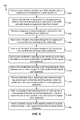
- a method 500 for providing a LAG in a SDN is shown according to one embodiment.
- the method 500 may be executed by a system using a processor which is configured to execute or otherwise cause the execution of embedded or standalone logic (which may be hardware, software, or a combination thereof) according to one embodiment.
- the method 500 may be executed by a computer program product which comprises a computer readable storage medium having computer program code stored therein.
- the method 500 may be performed in accordance with the present invention in any of the environments depicted in FIGS. 1-4 among others, in various embodiments. Of course, more or less operations than those specifically described in FIG. 5 may be included in method 500 , as would be understood by one of skill in the art upon reading the present descriptions.
- each of the steps of the method 500 may be performed by any suitable component of the operating environment.
- the method 500 may be partially or entirely performed by a host, a server, a router, a switch, a switch controller (such as a SDN controller, an OpenFlow controller, etc.), a processor, e.g., a central processing unit (CPU), an application specific integrated circuit (ASIC), a field programmable gate array (FPGA), etc., one or more network interface cards (NICs), one or more virtual NICs, one or more virtualization platforms, or any other suitable device or component of a network system, cluster, or group of clusters.
- a host e.g., a server, a router, a switch, a switch controller (such as a SDN controller, an OpenFlow controller, etc.), a processor, e.g., a central processing unit (CPU), an application specific integrated circuit (ASIC), a field programmable gate array (FPGA), etc., one or more network interface cards (NICs
- a port addition indication is received at a SDN controller that a logical port is configured on a switching device.
- the switching device is connected to the SDN controller and a second device, and the logical port represents a LAG that comprises at least two links between the switching device and the second device, in one embodiment. In this way, the SDN controller is made aware of the presence of the logical port.
- the SDN may be configured according to OpenFlow standards, and the SDN controller may adhere to OpenFlow standards.
- OpenFlow any other known switch communication protocol and/or standard may be used, as would be known to one of skill in the art.
- a logical index is derived and maintained for all logical ports in software-defined switching devices connected to the SDN controller based on logical port identifiers thereof. This includes adding the logical port indicated in operation 502 to the logical index.
- the port addition indication may be a port status message that includes at least a logical port identifier for the logical port. Using this logical port identifier, the SDN controller may add the logical port to the logical index.
- a logical port removal indication may be received from the switching device.
- the logical port removal indication may be a port remove message that includes the logical index for the logical port, in one approach.
- the logical port may be removed from the logical index.
- an indication of a speed change for the logical port may be received from the switching device.
- the indication of the speed change may represent one or more membership changes for the logical port.
- the speed for the logical port may be stored in association with the logical port identifier, such as in the logical index.
- an indication of a status change for the logical port may be received from the switching device.
- the status change may represent whether the logical port is operational or non-operational in one approach.
- an operational status or a non-operational status may be indicated for the logical port, such as in the logical index or some other construct.
- a port modification message may be sent to the switching device that indicates one or more modifications to operation of the logical port.
- the port modification message may indicate at least one of: stop all packets on the logical port, enable the logical port, and disable the logical port, among other possible port modifications known in the art.
- a flow modification message may be sent to the switching device that indicates one or more changes to a flow profile for the logical port.
- the flow profile may be set according to standards, practices, and knowledge available to those of skill in the art. For example, tools available in OpenFlow may be used to set the flow profile for the switching device.
- indication that a packet has been received on the logical port may be received when the switching device receives the packet in via the logical port.
- a message comprising one or more packets to be sent out via the logical port may be sent to the switching device, in order to cause the one or more packets to be sent out via the logical port (LAG).
- LAG logical port
- a statistics request may be sent to the switching device to request statistics related to the logical port from the switching device.
- the statistics request may include requested statistics relating to the logical port, the switching device, or any other action, function, or system with which the switching device is capable of acquiring statistics.
- the statistics may include any traceable or measurable parameter known in the art, such as packets sent, packets received, delay, time lag, etc.
- a method 600 for providing a LAG in a SDN is shown according to one embodiment.
- the method 600 may be executed by a system using a processor which is configured to execute or otherwise cause the execution of embedded or standalone logic (which may be hardware, software, or a combination thereof) according to one embodiment.
- the method 600 may be executed by a computer program product which comprises a computer readable storage medium having computer program code stored therein.
- the method 600 may be performed in accordance with the present invention in any of the environments depicted in FIGS. 1-4 among others, in various embodiments. Of course, more or less operations than those specifically described in FIG. 6 may be included in method 600 , as would be understood by one of skill in the art upon reading the present descriptions.
- each of the steps of the method 600 may be performed by any suitable component of the operating environment.
- the method 600 may be partially or entirely performed by a host, a server, a router, a switch, a switch controller (such as a SDN controller, an OpenFlow controller, etc.), a processor, e.g., a CPU, an ASIC, a FPGA, etc., one or more NICs, one or more virtual NICs, one or more virtualization platforms, or any other suitable device or component of a network system, cluster, or group of clusters.
- a host e.g., a server, a router, a switch, a switch controller (such as a SDN controller, an OpenFlow controller, etc.), a processor, e.g., a CPU, an ASIC, a FPGA, etc., one or more NICs, one or more virtual NICs, one or more virtualization platforms, or any other suitable device or component of a network system, cluster, or group of clusters.
- a port addition indication may be sent to a SDN controller when a logical port is configured on a switching device in the SDN. This provides the SDN controller with indication that the logical port (LAG) is setup and ready to be utilized.
- LAG logical port
- a logical port removal indication may be sent to the SDN controller when the logical port is removed from the SDN, so that the SDN controller no longer attempts to send traffic via the logical port.
- an indication of a speed change for the logical port may be sent, such as to the SDN controller, when one or more ports are added as member ports of the logical port and/or when one or more member ports of the logical port are removed to reflect a change in overall speed of the logical port based on the one or more membership changes.
- an indication of a status change for the logical port may be sent, such as to the SDN controller, in response to the logical port changing from operational to non-operational or from non-operational to operational. In this way, the SDN controller is made aware of the operational status for the logical port.
- a port modification message may be received, such as from the SDN controller, and operation of the logical port may be modified according to instructions in the port modification message.
- the SDN controller is able to request specific changes to operation of the logical port, according to protocols and standards known in the art, such as OpenFlow among others.
- a flow modification message may be received, such as from the SDN controller, and a flow profile may be changed for the logical port according to instructions in the flow modification message.
- the SDN controller is able to request specific changes to the flow profile of the logical port, according to protocols and standards known in the art, such as OpenFlow among others.
- an indication that a packet has been received on the logical port may be sent, such as to the SDN controller, when the switching device receives the packet in via the logical port. This provides the SDN controller with notice of packets being received on the logical port.
- a message comprising one or more packets to be sent out via the logical port may be received, such as from the SDN controller, the one or more packets may be extracted therefrom, and the one or more packets may be sent out via the logical port thereafter.
- a statistics request may be received, such as from the SDN controller, that includes requested statistics, the requested statistics may be aggregated, and the requested statistics may be sent back to the SDN controller, in one embodiment.
- the present invention may be a system, a method, and/or a computer program product.
- the computer program product may include a computer readable storage medium (or media) having computer readable program instructions thereon for causing a processor to carry out aspects of the present invention.
- the computer readable storage medium can be a tangible device that can retain and store instructions for use by an instruction execution device.
- the computer readable storage medium may be, for example, but is not limited to, an electronic storage device, a magnetic storage device, an optical storage device, an electromagnetic storage device, a semiconductor storage device, or any suitable combination of the foregoing.
- a non-exhaustive list of more specific examples of the computer readable storage medium includes the following: a portable computer diskette, a hard disk, a random access memory (RAM), a read-only memory (ROM), an erasable programmable read-only memory (EPROM or Flash memory), a static random access memory (SRAM), a portable compact disc read-only memory (CD-ROM), a digital versatile disk (DVD), a memory stick, a floppy disk, a mechanically encoded device such as punch-cards or raised structures in a groove having instructions recorded thereon, and any suitable combination of the foregoing.
- RAM random access memory
- ROM read-only memory
- EPROM or Flash memory erasable programmable read-only memory
- SRAM static random access memory
- CD-ROM compact disc read-only memory
- DVD digital versatile disk
- memory stick a floppy disk
- a mechanically encoded device such as punch-cards or raised structures in a groove having instructions recorded thereon
- a computer readable storage medium is not to be construed as being transitory signals per se, such as radio waves or other freely propagating electromagnetic waves, electromagnetic waves propagating through a waveguide or other transmission media (e.g., light pulses passing through a fiber-optic cable), or electrical signals transmitted through a wire.
- Computer readable program instructions described herein can be downloaded to respective computing/processing devices from a computer readable storage medium or to an external computer or external storage device via a network, for example, the Internet, a local area network, a wide area network and/or a wireless network.
- the network may comprise copper transmission cables, optical transmission fibers, wireless transmission, routers, firewalls, switches, gateway computers and/or edge servers.
- a network adapter card or network interface in each computing/processing device receives computer readable program instructions from the network and forwards the computer readable program instructions for storage in a computer readable storage medium within the respective computing/processing device.
- Computer readable program instructions for carrying out operations of the present invention may be assembler instructions, instruction-set-architecture (ISA) instructions, machine instructions, machine dependent instructions, microcode, firmware instructions, state-setting data, or either source code or object code written in any combination of one or more programming languages, including an object oriented programming language such as Smalltalk, C++ or the like, and conventional procedural programming languages, such as the “C” programming language or similar programming languages.
- the computer readable program instructions may execute entirely on the user's computer, partly on the user's computer, as a stand-alone software package, partly on the user's computer and partly on a remote computer or entirely on the remote computer or server.
- the remote computer may be connected to the user's computer through any type of network, including a local area network (LAN) or a wide area network (WAN), or the connection may be made to an external computer (for example, through the Internet using an Internet Service Provider).
- electronic circuitry including, for example, programmable logic circuitry, field-programmable gate arrays (FPGA), or programmable logic arrays (PLA) may execute the computer readable program instructions by utilizing state information of the computer readable program instructions to personalize the electronic circuitry, in order to perform aspects of the present invention.
- These computer readable program instructions may be provided to a processor of a general purpose computer, special purpose computer, or other programmable data processing apparatus to produce a machine, such that the instructions, which execute via the processor of the computer or other programmable data processing apparatus, create means for implementing the functions/acts specified in the flowchart and/or block diagram block or blocks.
- These computer readable program instructions may also be stored in a computer readable storage medium that can direct a computer, a programmable data processing apparatus, and/or other devices to function in a particular manner, such that the computer readable storage medium having instructions stored therein comprises an article of manufacture including instructions which implement aspects of the function/act specified in the flowchart and/or block diagram block or blocks.
- the computer readable program instructions may also be loaded onto a computer, other programmable data processing apparatus, or other device to cause a series of operational steps to be performed on the computer, other programmable apparatus or other device to produce a computer implemented process, such that the instructions which execute on the computer, other programmable apparatus, or other device implement the functions/acts specified in the flowchart and/or block diagram block or blocks.
- each block in the flowchart or block diagrams may represent a module, segment, or portion of instructions, which comprises one or more executable instructions for implementing the specified logical function(s).
- the functions noted in the block may occur out of the order noted in the figures.
- two blocks shown in succession may, in fact, be executed substantially concurrently, or the blocks may sometimes be executed in the reverse order, depending upon the functionality involved.
- a system may include a processor and logic integrated with and/or executable by the processor, the logic being configured to perform one or more of the process steps recited herein.
- the processor has logic embedded therewith as hardware logic, such as an ASIC, a FPGA, etc.
- the logic is hardware logic; software logic such as firmware, part of an operating system, part of an application program; etc., or some combination of hardware and software logic that is accessible by the processor and configured to cause the processor to perform some functionality upon execution by the processor.
- Software logic may be stored on local and/or remote memory of any memory type, as known in the art. Any processor known in the art may be used, such as a software processor module and/or a hardware processor such as an ASIC, a FPGA, a CPU, an integrated circuit (IC), etc.
- embodiments of the present invention may be provided in the form of a service deployed on behalf of a customer to offer service on demand.
- a system in the context of FIGS. 5-6 , may include, according to one embodiment, a SDN controller comprising a processor and logic integrated with and/or executable by the processor.
- the logic may be configured to receive a port addition indication that a logical port is configured on a switching device, the switching device being connected to the SDN controller and a second device, wherein the logical port represents a LAG that comprises at least two links between the switching device and the second device, and derive and maintain a logical index for all logical ports in software-defined switching devices connected to the SDN controller based on logical port identifiers thereof.
- a computer program product in the context of FIGS. 5-6 , may include, according to one embodiment, a computer readable storage medium having program code embodied therewith.
- the program code may be readable and/or executable by a processor to cause the processor to: send a port addition indication to a SDN controller when a logical port is configured on a switching device in the SDN, the switching device being connected to the SDN controller and a second device, wherein the logical port represents a LAG that comprises at least two links between the switching device and the second device, send a logical port removal indication to the SDN controller when the logical port is removed from the SDN, send an indication of a speed change for the logical port when one or more ports are added as member ports of the logical port and/or when one or more member ports of the logical port are removed to reflect a change in overall speed of the logical port based on the one or more membership changes, and send an indication of a status change for the logical port to the SDN controller in response to the logical port changing
Abstract
Description
Claims (20)
Priority Applications (2)
| Application Number | Priority Date | Filing Date | Title |
|---|---|---|---|
| US14/231,258 US9559946B2 (en) | 2014-03-31 | 2014-03-31 | Link aggregation group (LAG) support on a software-defined network (SDN) |
| US15/384,086 US10148556B2 (en) | 2014-03-31 | 2016-12-19 | Link aggregation group (LAG) support on a software-defined network (SDN) |
Applications Claiming Priority (1)
| Application Number | Priority Date | Filing Date | Title |
|---|---|---|---|
| US14/231,258 US9559946B2 (en) | 2014-03-31 | 2014-03-31 | Link aggregation group (LAG) support on a software-defined network (SDN) |
Related Child Applications (1)
| Application Number | Title | Priority Date | Filing Date |
|---|---|---|---|
| US15/384,086 Continuation US10148556B2 (en) | 2014-03-31 | 2016-12-19 | Link aggregation group (LAG) support on a software-defined network (SDN) |
Publications (2)
| Publication Number | Publication Date |
|---|---|
| US20150281072A1 US20150281072A1 (en) | 2015-10-01 |
| US9559946B2 true US9559946B2 (en) | 2017-01-31 |
Family
ID=54191937
Family Applications (2)
| Application Number | Title | Priority Date | Filing Date |
|---|---|---|---|
| US14/231,258 Active 2035-06-27 US9559946B2 (en) | 2014-03-31 | 2014-03-31 | Link aggregation group (LAG) support on a software-defined network (SDN) |
| US15/384,086 Active US10148556B2 (en) | 2014-03-31 | 2016-12-19 | Link aggregation group (LAG) support on a software-defined network (SDN) |
Family Applications After (1)
| Application Number | Title | Priority Date | Filing Date |
|---|---|---|---|
| US15/384,086 Active US10148556B2 (en) | 2014-03-31 | 2016-12-19 | Link aggregation group (LAG) support on a software-defined network (SDN) |
Country Status (1)
| Country | Link |
|---|---|
| US (2) | US9559946B2 (en) |
Cited By (1)
| Publication number | Priority date | Publication date | Assignee | Title |
|---|---|---|---|---|
| US10616106B2 (en) * | 2017-12-06 | 2020-04-07 | Futurewei Technologies, Inc. | Establishing virtual network routes in a computer network |
Families Citing this family (13)
| Publication number | Priority date | Publication date | Assignee | Title |
|---|---|---|---|---|
| US9722896B2 (en) * | 2014-06-25 | 2017-08-01 | Avago Technologies General Ip (Singapore) Pte. Ltd. | Micro-OAM for link groups |
| US9503338B2 (en) * | 2014-07-24 | 2016-11-22 | Ciena Corporation | Systems and methods to detect and propagate UNI operational speed mismatch in ethernet services |
| US9860350B2 (en) | 2015-05-12 | 2018-01-02 | Huawei Technologies Co., Ltd. | Transport software defined networking (SDN)—logical to physical topology discovery |
| US10425319B2 (en) * | 2015-05-21 | 2019-09-24 | Huawei Technologies Co., Ltd. | Transport software defined networking (SDN)—zero configuration adjacency via packet snooping |
| US10015053B2 (en) * | 2015-05-21 | 2018-07-03 | Huawei Technologies Co., Ltd. | Transport software defined networking (SDN)—logical link aggregation (LAG) member signaling |
| US10218641B2 (en) * | 2015-10-09 | 2019-02-26 | Arris Enterprises Llc | Handling dynamic cascade port/LAG changes in a non-blocking manner |
| US10148595B2 (en) * | 2015-10-16 | 2018-12-04 | Arris Enterprises Llc | Handling dynamic port/LAG changes without breaking communication in an extended bridge |
| KR20170087602A (en) * | 2016-01-21 | 2017-07-31 | 현대자동차주식회사 | Method for converting operation mode in network |
| CN106100900A (en) * | 2016-08-02 | 2016-11-09 | 浪潮集团有限公司 | A kind of monitoring method of SDN middle port state |
| US10581688B2 (en) * | 2017-06-19 | 2020-03-03 | Quanta Computer Inc. | Methods for automatically configuring multiple chassis link aggregation group (MC-LAG) |
| CN109936505B (en) * | 2017-12-15 | 2021-06-22 | 上海诺基亚贝尔股份有限公司 | Method and apparatus in data-centric software-defined networks |
| CN108390821B (en) * | 2018-02-27 | 2020-11-27 | 盛科网络(苏州)有限公司 | Method and system for realizing dual activities of openflow switch |
| US10887408B2 (en) * | 2018-08-07 | 2021-01-05 | Hewlett Packard Enterprise Development Lp | Remote monitoring of network communication devices |
Citations (4)
| Publication number | Priority date | Publication date | Assignee | Title |
|---|---|---|---|---|
| US20090240790A1 (en) * | 2008-03-24 | 2009-09-24 | Hitachi, Ltd. | Network Switching Apparatus, Server System and Server Migration Method for Server System |
| US20110188373A1 (en) | 2010-02-01 | 2011-08-04 | Shuichi Saito | Interface control system and interface control method |
| US20130108263A1 (en) * | 2011-11-01 | 2013-05-02 | Plexxi Inc. | Data center network architecture |
| WO2013066602A1 (en) | 2011-11-01 | 2013-05-10 | Plexxi Inc. | Data center network architecture |
Family Cites Families (3)
| Publication number | Priority date | Publication date | Assignee | Title |
|---|---|---|---|---|
| US6697087B1 (en) * | 1999-05-05 | 2004-02-24 | Microsoft Corporation | Updating diagrams of dynamic representational Models of dynamic systems |
| EP2814213A4 (en) * | 2012-02-10 | 2015-09-09 | Nec Corp | Control device, communication system, communication method and program |
| US20150172222A1 (en) * | 2013-12-16 | 2015-06-18 | James Liao | Data center ethernet switch fabric |
-
2014
- 2014-03-31 US US14/231,258 patent/US9559946B2/en active Active
-
2016
- 2016-12-19 US US15/384,086 patent/US10148556B2/en active Active
Patent Citations (4)
| Publication number | Priority date | Publication date | Assignee | Title |
|---|---|---|---|---|
| US20090240790A1 (en) * | 2008-03-24 | 2009-09-24 | Hitachi, Ltd. | Network Switching Apparatus, Server System and Server Migration Method for Server System |
| US20110188373A1 (en) | 2010-02-01 | 2011-08-04 | Shuichi Saito | Interface control system and interface control method |
| US20130108263A1 (en) * | 2011-11-01 | 2013-05-02 | Plexxi Inc. | Data center network architecture |
| WO2013066602A1 (en) | 2011-11-01 | 2013-05-10 | Plexxi Inc. | Data center network architecture |
Cited By (1)
| Publication number | Priority date | Publication date | Assignee | Title |
|---|---|---|---|---|
| US10616106B2 (en) * | 2017-12-06 | 2020-04-07 | Futurewei Technologies, Inc. | Establishing virtual network routes in a computer network |
Also Published As
| Publication number | Publication date |
|---|---|
| US20150281072A1 (en) | 2015-10-01 |
| US20170099215A1 (en) | 2017-04-06 |
| US10148556B2 (en) | 2018-12-04 |
Similar Documents
| Publication | Publication Date | Title |
|---|---|---|
| US10148556B2 (en) | Link aggregation group (LAG) support on a software-defined network (SDN) | |
| US10432475B2 (en) | Mapping relationships among virtual elements across a system | |
| US9749402B2 (en) | Workload deployment with real-time consideration of global network congestion | |
| US9544248B2 (en) | Overlay network capable of supporting storage area network (SAN) traffic | |
| US9602400B2 (en) | Hypervisor independent network virtualization | |
| US9692689B2 (en) | Reporting static flows to a switch controller in a software-defined network (SDN) | |
| US10177936B2 (en) | Quality of service (QoS) for multi-tenant-aware overlay virtual networks | |
| WO2016034074A1 (en) | Method, apparatus and system for implementing software-defined networking (sdn) | |
| US9678912B2 (en) | Pass-through converged network adaptor (CNA) using existing ethernet switching device | |
| US20130223277A1 (en) | Disjoint multi-pathing for a data center network | |
| US9590855B2 (en) | Configuration of transparent interconnection of lots of links (TRILL) protocol enabled device ports in edge virtual bridging (EVB) networks | |
| US10205648B1 (en) | Network monitoring using traffic mirroring and encapsulated tunnel in virtualized information processing system | |
| US8966148B2 (en) | Providing real-time interrupts over Ethernet | |
| US9641380B2 (en) | Spanning tree protocol (STP) implementation on an event driven virtual link aggregation (vLAG) system | |
| Cherkaoui et al. | Virtualization, cloud, sdn, and sddc in data centers | |
| Chhikara et al. | Towards OpenFlow based software defined networks | |
| OpenStack | Mellanox Reference Architecture for Red Hat Enterprise Linux OpenStack Platform 4.0 |
Legal Events
| Date | Code | Title | Description |
|---|---|---|---|
| AS | Assignment |
Owner name: INTERNATIONAL BUSINESS MACHINES CORPORATION, NEW Y Free format text: ASSIGNMENT OF ASSIGNORS INTEREST;ASSIGNORS:ARUMUGAM, SIVAKUMAR;BHAGAVATHIPERUMAL, CHIDAMBARAM;KODAMALA, DILLIBABU;AND OTHERS;SIGNING DATES FROM 20140328 TO 20140331;REEL/FRAME:032578/0308 |
|
| AS | Assignment |
Owner name: LENOVO ENTERPRISE SOLUTIONS (SINGAPORE) PTE. LTD., SINGAPORE Free format text: ASSIGNMENT OF ASSIGNORS INTEREST;ASSIGNOR:INTERNATIONAL BUSINESS MACHINES CORPORATION;REEL/FRAME:034194/0353 Effective date: 20140926 Owner name: LENOVO ENTERPRISE SOLUTIONS (SINGAPORE) PTE. LTD., Free format text: ASSIGNMENT OF ASSIGNORS INTEREST;ASSIGNOR:INTERNATIONAL BUSINESS MACHINES CORPORATION;REEL/FRAME:034194/0353 Effective date: 20140926 |
|
| FEPP | Fee payment procedure |
Free format text: PAYOR NUMBER ASSIGNED (ORIGINAL EVENT CODE: ASPN); ENTITY STATUS OF PATENT OWNER: LARGE ENTITY |
|
| STCF | Information on status: patent grant |
Free format text: PATENTED CASE |
|
| AS | Assignment |
Owner name: LENOVO GLOBAL TECHNOLOGIES INTERNATIONAL LTD, HONG Free format text: ASSIGNMENT OF ASSIGNORS INTEREST;ASSIGNOR:LENOVO ENTERPRISE SOLUTIONS (SINGAPORE) PTE LTD.;REEL/FRAME:050298/0565 Effective date: 20170401 |
|
| MAFP | Maintenance fee payment |
Free format text: PAYMENT OF MAINTENANCE FEE, 4TH YEAR, LARGE ENTITY (ORIGINAL EVENT CODE: M1551); ENTITY STATUS OF PATENT OWNER: LARGE ENTITY Year of fee payment: 4 |
|
| MAFP | Maintenance fee payment |
Free format text: PAYMENT OF MAINTENANCE FEE, 8TH YEAR, LARGE ENTITY (ORIGINAL EVENT CODE: M1552); ENTITY STATUS OF PATENT OWNER: LARGE ENTITY Year of fee payment: 8 |