US955868A - Engraving-machine. - Google Patents
Engraving-machine. Download PDFInfo
- Publication number
- US955868A US955868A US51188609A US1909511886A US955868A US 955868 A US955868 A US 955868A US 51188609 A US51188609 A US 51188609A US 1909511886 A US1909511886 A US 1909511886A US 955868 A US955868 A US 955868A
- Authority
- US
- United States
- Prior art keywords
- carriage
- follower
- movement
- platen
- plane
- Prior art date
- Legal status (The legal status is an assumption and is not a legal conclusion. Google has not performed a legal analysis and makes no representation as to the accuracy of the status listed.)
- Expired - Lifetime
Links
Images



Classifications
-
- B—PERFORMING OPERATIONS; TRANSPORTING
- B44—DECORATIVE ARTS
- B44B—MACHINES, APPARATUS OR TOOLS FOR ARTISTIC WORK, e.g. FOR SCULPTURING, GUILLOCHING, CARVING, BRANDING, INLAYING
- B44B3/00—Artists' machines or apparatus equipped with tools or work holders moving or able to be controlled substantially two-dimensionally for carving, engraving, or guilloching shallow ornamenting or markings
- B44B3/001—Artists' machines or apparatus equipped with tools or work holders moving or able to be controlled substantially two-dimensionally for carving, engraving, or guilloching shallow ornamenting or markings by copying
-
- Y—GENERAL TAGGING OF NEW TECHNOLOGICAL DEVELOPMENTS; GENERAL TAGGING OF CROSS-SECTIONAL TECHNOLOGIES SPANNING OVER SEVERAL SECTIONS OF THE IPC; TECHNICAL SUBJECTS COVERED BY FORMER USPC CROSS-REFERENCE ART COLLECTIONS [XRACs] AND DIGESTS
- Y10—TECHNICAL SUBJECTS COVERED BY FORMER USPC
- Y10T—TECHNICAL SUBJECTS COVERED BY FORMER US CLASSIFICATION
- Y10T409/00—Gear cutting, milling, or planing
- Y10T409/30—Milling
- Y10T409/30084—Milling with regulation of operation by templet, card, or other replaceable information supply
- Y10T409/301176—Reproducing means
- Y10T409/301568—Reproducing means by use of pivotally supported tracer
Definitions
- This invention relates to machines that operate on the principle of the pantograph and is in the nature of an improvement of the machine that is set forth in Patent No. 703,719 granted to WV. E. Crane, July 1st, 1902.
- One of the objects of the invention is to simplify the mechanism as well as to secure more nearly accurate results, by reducing the connections between the follower and the shaft that gives the horizontal movements universally of the platen.
- Another object of the invention is to provide a construction in which the horizontal movements of the follower will cause resulting movements of the platen in absolutely the same plane.
- Another object of the invention is to provide improved means of adjustment to vary the ratio of vertical movement of the platen from the vertical movement of the follower; and furthermore to provide means whereby the vertical connecting member attached to the platen will be maintained in the same path of movement notwithstanding the said adjustments to vary the ratio.
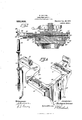
- FIG. 1 is a front elevation of the machine.
- Fig. 2 is a side elevation of the same, partly broken.
- Fig. 3 is a vertical section enlarged through the carriage and the shaft for operating the same, also showing the follower and connector.
- Fig. 4 is a view separately of the carriage and the platen.
- Fig. 5 shows the platen and the follower, with the operative means connecting the same.
- Fig. (3 shows enlarged the joint between the follower and the carriage shaft.
- Fig. 7 is a vertical section taken axially through the shaft of the part shown in Fig. 6.
- Fig. 8 is another section of the part shown in Fig. (5 taken at right angles with the shaft axis.
- Fig. 1 is a front elevation of the machine.
- Fig. 2 is a side elevation of the same, partly broken.
- Fig. 3 is a vertical section enlarged through the carriage and the shaft for operating the same, also showing the follower and connector.
- Fig. 4 is
- Fig. 9 shows the lever for operating the platen being a section on line 99 of Fig. 11.
- Fig. 10 shows enlarged the supporting and adjusting means for the lever.
- Fig. 11 a section on the line 11-11 indicated in Fig. 10.
- Fig. 12 is a detail view enlarged showing the support at the rear of the carriage.
- Fig. 13 is a section on the line 13-13 indicated in Fig. 3; and
- Fig. 14 is a section on the line 14.-11 indicated in Fig. 8.
- the platen proper has a vertical movement on a carriage from the vertical movement of the follower.
- the carriage itself has a universal movement in a horizontal plane from the horizontal movement universally of the follower. From this it follows that the variation of the position of the carriage will have practically no effect on the movement given vertically to a platen by the follower.
- the platen will partake of the horizontal movements in all directions of the carriage as if fixed thereon; but at the same time the platen is free for vertical shifting by the follower in all positions of movement of the carriage.
- the carriage or platen had its operating shaft for universal movement in the horizontal plane, connected with the follower by an intermediate lever, and the upper end of the follower member had a universal pivotin a-stationary member.
- the follower is directly connected with the operating shaft for the carriage.
- the only means of adjustment provided was in the variation of the length of the connector between the follower and the lever connected with the platen for vertical movement.
- the said lever connected between the connector and the member attached to the car-- riage or platen has its fulcrum adjustable to vary the ratio of movement imparted to the platen from the movement of the connector and follower.
- the frame of the machine is denoted generally by 12 and carries a bed plate 13 on which any suitable pattern P may be clamped in any suitable manner, which pattern is to be engaged by the follower mem ber of the machine.
- a suitable tool member T is shown mounted on a spindle 14-rotated in any suitable manner such as by a friction device comprising a'wheel 15 on the spindle engaging a friction wheel 16 mounted on the main shaft 17 of the machine, which latter shaft may be driven from a source of power in any desired manner.
- the blank to be operated upon by the tool is supported by a carriage member denoted generally by 20, shown separately in Fig. 4.
- This carriage is supported to move in all directions in a given plane, preferably a horizontal one.
- the blank is not directly secured to this carriage but is fastened to a platen member 21. that is vertically inovable in a slotted portion 22 in'the front wall of the carrier; the platen being located directly underneath the tool.
- a tubular shaft 23 isrotatable along a bearing portion 24 in the frame, and is also endwise movable therein, see Fig. 3.
- This shaft has gear portions 25 and 26 on opposite sides of the bearing portion, that are engaged by rack portions 27 and 28 on the side members a and b of the carriage; the carriage racks being retained in engagement with these gears by means of springs 29 and 30.
- a universally shifting engaging device is provided between the carriage and the frame.
- the carriage is shown provided with a channeled guide 31, and the frame is provided with a spindle 32 (see Figs. 2 and 12) on which is loosely mounted a wheel or pulley 33 to be rotatable and endwise movable thereon.
- the said springs press the guide of the carriage into engagement with this wheel, and rotation of the said sleeve 23 through its gears and the racks, will move the carriage back and forth, which by reason of the en gagement with the wheel will cause the carriage to move in a certain plane.
- This wheel and guide will permit shifting of the carriage in a direction axially of the sleeve shaft, because the wheel 33 can move axially on its spindle.
- the sleeve shaft is itself moved endwise, and a suitable connection is provided causing the carriage to travel therewith.
- a gib 34 secured to the carriage engages a groove wheel 35 fast on the spindle 23, that will permit the shifting of the.
- the follower member denoted generally by 36 is pivotally suspended from the outer end of the sleeve shaft whereby the swinging of the follower will rock the shaft on its axis.
- the follower is also connected to the shaft whereby the swinging of the follower in a plane parallel with the axis of the shaft will cause endwise movement of the shaft; and the compounding of these two movements of the follower will result in a similar movement being imparted to the carriage, by reason of the said shaft sleeve being moved endwise and rocked at the same time.
- the follower member is shown comprising a pattern-engaging socket portion 37 in which slides a stem 38, and the latter is adjustable in a socket portion 39 to vary the length of the follower when desired, for
- the follower portion 39 has forked arms 40 and 41 containing sockets 42 and 43, into which extend bearing screws 44 and 45 from arms 46 and 47 on the end portion .48 of the sleeve 23.
- the follower can swingv which passes a rod 50, carrying a sleeve 51- that at its outer end has forked arms 52 and 53, that are slotted to engage a pin 54 car.- ried in apertures in lugs 55 and 56 extend ing downward from a block 57.
- This block is adjustable on the extension 58 of the follower member 39 by a bolt 59 passing through a slot 60 in the block and screwed into the extension 58. By this means the block is adjusted until the pin 54 lies in the axis of the sleeve 23.
- the rod 50 has an eye portion 61 at its outer end that engages the said pin 54 and is located between the lugs 55 and 56 of the block 57.
- the coil spring 62 surrounds the rod on the other side of the stud 49 and extends between the stud and a nut 63 on the end of the rod. This spring will pull the rod through the stud and its eye 61 will pull the pin 54 inward, causing the sleeve 51 to press against the stud 49, that is preferably tapered at its opening and the sleeve end is correspondingly rounded. This arrangement will cause the follower to swing on the pivot pin 54 that is prevented from movement in a direction axially of the shaft, by reason of the rod holding the sleeve against the stud.
- a bracket on which is mounted a lever 71.
- a connecting rod 73 that has its lower end rounded and entering a socket 74 in the lever while its upper end is also rounded and enters a socket in a lug 75 on the platen.
- a connector 76 is hinged to the follower member 37 at 77 and its lower member is connected to a block 78 that is pivotally connected to the other end of the lever 71. The vertical movement of the follower through the connector will swing the lever 71 and this will cause vertical movement of the connecting rod 73.
- a spring 10 connected between the platen and the bracket and will press the two ends of the connecting rod into the sockets, provided therefor.
- Suitable means are provided for adjusting the fulcrum of this lever and means are also provided for retaining the vertical connecting rod in its same path of movement in View of such adjustment of the fulcrum of the lever.
- the lever 71 is endwise movable in a cradle 79 (see Fig. 10) and locked therein by means of one or more screws 80 passing through the cradle into a channel 81 in the lever.
- the cradle is thereby locked to the lever, and the cradle is pivoted in a block 82 by means of screws 83 and 84 passin through the two sides thereof into suitab e sockets in the sides of the cradle.
- the shifting of the lever in its cradle that can be observed by means of a scale 85 on the cradle opposite a mark 86 on the lever, will shift the fulcrum of the lever relative to its engagement with the vertical rod 73 and with the connector 76 at the opposite end. But this shifting of the lever in the cradle, will shift the path of movement of the vertical rod 7 3.
- the block 82 carrying the pivot screws for the cradle is itself made movable parallel with the lever.
- This block has a tongue 87 extending into a channel 88 in the bracket 70 and the block is shifted until its scale 89 registering with a mark 90 on the bracket indicates a corresponding movement in the opposite direction as shifted in its supporting bracket.
- the blank is suitably clamped on the platen to'be e11- gaged by the tool T; and a pattern P is suitably secured to the bed plate 13.
- the follower member 37 has its lower end brought into en agement with the pattern, it being vertical y shiftable on the follower stem 38, its vertical movements will through the connector 7 6 rock lever 71, to reciprocate the platen 21, through rod 73. All the lateral movements of the follower sleeve 37 will cause the follower sleeve 39 to rock on its pivot attachment with the sleeve shaft 23 to reciprocate the shaft, or else will rock the shaft 23 on its axis, or both of these movements will take place.
- a carriage supported for movement in all, directions in a certain plane, a follower, operative connections be tween the follower and the carriage causing movements of the carriage similar to the movements of the follower in a given plane, a platen movable on the carriage in a path perpendicular to the plane of movement of the carriage, and operative connections between the follower and the platen effective to cause the movements of the follower in a direction at right angles to its said movements in a certain plane, to cause corresponding movements of the platen on the carriage, and such movements being efi'ective notwithstanding the said shifting of the carriage in its said plane of movement.
- a carriage supported for movement in all directions in a certain plane, a follower, operative connections between the follower and the carriage causing movements of the carriage similar to the movements of the follower in thesame direction in a given plane, a platen movable on the carriage in a path perpendicular to said plane of movement of the carriage, and operative connections between the follower and the platen effective to cause the movements of the follower in a direction at right angles to its said movements in a certain plane, to cause corresponding movements of the platen on the carriage, and such movements being effective notwithstanding the said shifting of the carriage in its said plane of movement.
- a carriage supported for movement in all directions in a horizontal plane, a follower, operative connections between the follower and the carriage causing movements of thecarriage similar to the movements of the follower in the same direction in said plane, a platen movable on the carriage in a vertical path, and operative connections between the follower and the platen effective to cause the vertical movements of the follower tocause corresponding movements in a vertical direction of the platen on the carriage, and such movements being effective notwithstanding the said shifting of the carriage in its said plane of movement.
- a carriage supported for movement in all directions in a certain plane, a follower, operative connections between the follower and the carriage causing movements of the carriage similar to the movements of the follower in a given plane, a platen movable on the carriage in a path perpendicular to the plane of movement of the carriage, and operative connections between the follower and the platen effective to cause the movements of the follower in a direction at right angles to its said movements in 'a. certain plane, to cause corresponding movements of the platen on the carriage, and such movements being effective notwithstanding the said shifting of the carriage in all directions in its said plane of movement, and means for varying the ratio of movement given to the platen by the follower.
- a carriage supported for movement in all directions in a certain plane, a follower, operative connections between the follower and the carriage causing movement of the carriage similar to the movements of the follower in the same direction in a given plane, a platen movable on the carriage in a path perpendicular to the plane of movement of the carriage, operative connections between the follower and the platen effective to cause the movements of the follower in a direction at right angles to its said movements in a certain plane, to cause corresponding movements ofv the platen on the carriage, and such movements being effective notwithstanding the said shifting of the carriage in all directions in its said plane of movement, comprising a lever pivoted below said platen, a rod pivotally connecting the lever with the platen, and a connector between the follower and said lever whereby the movements of the follower in a direction perpendicular to its plane of movement will cause similar movements of the platen.
- a carriage supported for movement in all directions in a certain plane, a follower, operative connections between the follower and the carriage causing movement of the carriage similar to the movement of the follower in the same direction in a given plane, a platen movable on the carriage in a path perpendicular to the plane .of movement of the carriage, operative connections between the follower and the platen effective to cause the movement of the follower in a direction at right angles to its said movement in a certain planeyto cause corresponding movement of the platen on the carriage, and such movement being effective notwithstanding the said shifting of the carriage in all directions in its said plane of movement, a lever pivoted below said platen, a rod pivotally connecting the lever with the platen, and a connector between the follower and said lever whereby the movement of the follower in a direction perpendicular to its plane of movement will cause similar movement of the platen, said.
- a carriage supported for movement in all directions in a certain plane, a follower, operative connections between the follower and the carriage causing movement of the carriage similar to the movements of the follower in the same direction 1n a glven plane, a platen movable on the carriage in a path perpendicular to the plane of movement of the carriage, operative connections between the follower and the platen effective to cause the movements of thefollower in a direction at right angles to its said movements in a certain plane, to cause corresponding movements of the platen on the carriage, and such movements being effective notwithstanding the said shifting of the carriage in all directions in its said plane of movement, a lever pivoted below said platen, a rod pivotally connecting the lever with the platen,'and a connector between the follower and said lever whereby the movements of the follower in a direction perpendicular to its plane of movement will cause similar movements of the platen, said lever having its fulcrum adjustable to vary the ratio of movement given the platen by the follower.
- a follower In combination, a follower, a bracket, a lever fulcrumed on the bracket, a connector between the lever and the follower, a platen vertically movable, a rod connecting the platen and said lever whereby the platen will be reciprocated from the vertical movements of the follower, a block on said bracket, a cradle pivoted on said block, said lever being secured in the cradle and endwise adjustable therein whereby the fulcrum of the lever is changed relative to the connector and the said rod to vary the swing of the rod from the connector, said block being adjustable on the bracket in a direction substantially parallel with the path of adjustment of the lever in the cradle, whereby the relative position of the rod and the bracket is maintained constant upon adjustment of the fulcrum of the lever.
- a carriage supported for movement in all directions in a certain plane, a follower, operative connections between the follower and the carriage causing movement of the carriage similar to the movements of the follower in the same direction in a given plane, a platen movable on the carriage in a path perpendicular to the plane of movement of the carriage, a lever pivoted below said platen, a rod pivotally connecting the lever with the platen, and a connector between the follower and said rod whereby the movements of the follower in a direction perpendicular to its plane of movement will cause similar movements of the platen.
- a carriage supported for movement in all directions in a certain plane, a follower, operative connections between the follower and the carriage causing movement of the carriage similar to the movements of the follower in the same direction in a given plane, a platen movable'on the carriage in a path perpendicular to the plane of movement of the carriage, a lever pivoted below said platen, a rod pivotally connecting the lever with the platen, and a connector between the follower and said movement of the carriage similar to the movements of the follower in the same direction'in a given plane, a lever pivoted below said platen, a rod pivotally connecting the lever with the platen, and aconnector between the follower and said lever whereby the movement of the'follower in a direction perpendicular to itsplane of move- 1 ment will cause similar movements of the platen, said lever having its fulcrum adjustable to vary the ratio of movement given the platen by the follower.
Landscapes
- Moulds For Moulding Plastics Or The Like (AREA)
Description
R. GRIESER.
ENGRAVING MACHINE.
APPLICATION FILED AUG. 0, 1909.
Patented Apr. 26, 1910.
4 sums-41mm 2.
WWW;
Wlnesses.
R. GRIESER.
ENGRAVING MACHINE.
.APPLIGATION FILED AUG.!), 1902 955, Batented Apr. 26, 1910.
R. GRIBSER.
BNGRAVING MACHINE.
APPLIOATION FILED AUG. 0, 1909 955,868. Patented Apr. 26, 1910.
4 SHEETS-SHEET 4.
UNITED STATES PATENT OFFICE.
RICHARD GRIESER, OF NEW YORK, N. Y., ASSIGNOR TO THE POLLARD-ALLING MANU- FACTURING 00., OF NEW YORK, N. Y., A CORPORATION OF NEW YORK.
ENGRAVING-MACHINE.
Specification of Letters Patent.
Patented Apr. 26, 1910.
Application filed August 9, 1909. Serial No. 511,886.
To all whom it may concern:
Be it known that I, RICHARD Gnmsun, a citizen of the United States, residing in New York city, in the county of New York and State of New York, have invented certain new and useful Improvements in Engraving-hlachines, of which the following is a specification.
This invention relates to machines that operate on the principle of the pantograph and is in the nature of an improvement of the machine that is set forth in Patent No. 703,719 granted to WV. E. Crane, July 1st, 1902.
One of the objects of the invention is to simplify the mechanism as well as to secure more nearly accurate results, by reducing the connections between the follower and the shaft that gives the horizontal movements universally of the platen.
Another object of the invention is to provide a construction in which the horizontal movements of the follower will cause resulting movements of the platen in absolutely the same plane.
Another object of the invention is to provide improved means of adjustment to vary the ratio of vertical movement of the platen from the vertical movement of the follower; and furthermore to provide means whereby the vertical connecting member attached to the platen will be maintained in the same path of movement notwithstanding the said adjustments to vary the ratio.
In the accompanying drawing representing an embodiment of my invention Figure 1 is a front elevation of the machine. Fig. 2 is a side elevation of the same, partly broken. Fig. 3 is a vertical section enlarged through the carriage and the shaft for operating the same, also showing the follower and connector. Fig. 4 is a view separately of the carriage and the platen. Fig. 5 shows the platen and the follower, with the operative means connecting the same. Fig. (3 shows enlarged the joint between the follower and the carriage shaft. Fig. 7 is a vertical section taken axially through the shaft of the part shown in Fig. 6. Fig. 8 is another section of the part shown in Fig. (5 taken at right angles with the shaft axis. Fig. 9 shows the lever for operating the platen being a section on line 99 of Fig. 11. Fig. 10 shows enlarged the supporting and adjusting means for the lever. Fig. 11 a section on the line 11-11 indicated in Fig. 10. Fig. 12 is a detail view enlarged showing the support at the rear of the carriage. Fig. 13 is a section on the line 13-13 indicated in Fig. 3; and Fig. 14 is a section on the line 14.-11 indicated in Fig. 8.
I n the machine shown in the said patent to Crane the platen or carriage is connected with a shaft by gearing, on the swinging of which shaft the carriage moved in a certain plane back and forth in a certain direction; and by endwise movement of the shaft the carriage was shifted in another direction in substantially the same plane. But for the vertical movements of the carriage resulting from the vertical movement of the follower, the carriage is swung on this said shaft as an axis. Now, at one limit of move ment of the carriage advanced by said gearing, upon a vertical movement being given to the carriage from the follower, it would move a certain distance proportional to its radius of swing from the axis of the shaft. But when the carriage was shifted in the opposite direction to its limit of movement by the operation of the gearing, obviously the radius of movement in this new position from the vertical movement of the platen, would be considerably different and thereafter the ratio of vertical movement given to the carriage would vary, with the result of error in the work done by the machine.
In the present invention the platen proper has a vertical movement on a carriage from the vertical movement of the follower. But the carriage itself has a universal movement in a horizontal plane from the horizontal movement universally of the follower. From this it follows that the variation of the position of the carriage will have practically no effect on the movement given vertically to a platen by the follower. Obviously, the platen will partake of the horizontal movements in all directions of the carriage as if fixed thereon; but at the same time the platen is free for vertical shifting by the follower in all positions of movement of the carriage.
In the said Crane patent the carriage or platen had its operating shaft for universal movement in the horizontal plane, connected with the follower by an intermediate lever, and the upper end of the follower member had a universal pivotin a-stationary member. In the present invention the follower is directly connected with the operating shaft for the carriage. In the said Crane patent the only means of adjustment provided was in the variation of the length of the connector between the follower and the lever connected with the platen for vertical movement. In the present invention the said lever connected between the connector and the member attached to the car-- riage or platen, has its fulcrum adjustable to vary the ratio of movement imparted to the platen from the movement of the connector and follower.
The frame of the machine is denoted generally by 12 and carries a bed plate 13 on which any suitable pattern P may be clamped in any suitable manner, which pattern is to be engaged by the follower mem ber of the machine. At the upper part of the machine a suitable tool member T is shown mounted on a spindle 14-rotated in any suitable manner such as by a friction device comprising a'wheel 15 on the spindle engaging a friction wheel 16 mounted on the main shaft 17 of the machine, which latter shaft may be driven from a source of power in any desired manner.
The blank to be operated upon by the tool is supported by a carriage member denoted generally by 20, shown separately in Fig. 4. This carriage is supported to move in all directions in a given plane, preferably a horizontal one. The blank is not directly secured to this carriage but is fastened to a platen member 21. that is vertically inovable in a slotted portion 22 in'the front wall of the carrier; the platen being located directly underneath the tool.
A tubular shaft 23 isrotatable along a bearing portion 24 in the frame, and is also endwise movable therein, see Fig. 3. This shaft has gear portions 25 and 26 on opposite sides of the bearing portion, that are engaged by rack portions 27 and 28 on the side members a and b of the carriage; the carriage racks being retained in engagement with these gears by means of springs 29 and 30. extending between the carriage and the frame. At the rear of the carriage a universally shifting engaging device is provided between it and the frame. The carriage is shown provided with a channeled guide 31, and the frame is provided with a spindle 32 (see Figs. 2 and 12) on which is loosely mounted a wheel or pulley 33 to be rotatable and endwise movable thereon. The said springs press the guide of the carriage into engagement with this wheel, and rotation of the said sleeve 23 through its gears and the racks, will move the carriage back and forth, which by reason of the en gagement with the wheel will cause the carriage to move in a certain plane. This wheel and guide will permit shifting of the carriage in a direction axially of the sleeve shaft, because the wheel 33 can move axially on its spindle. The sleeve shaft is itself moved endwise, and a suitable connection is provided causing the carriage to travel therewith. A gib 34 secured to the carriage, engages a groove wheel 35 fast on the spindle 23, that will permit the shifting of the.
carriage by rotation of the sleeve, yet will cause the carriage to move with the spindle when it is endwise shifted.
The follower member denoted generally by 36, is pivotally suspended from the outer end of the sleeve shaft whereby the swinging of the follower will rock the shaft on its axis. The follower is also connected to the shaft whereby the swinging of the follower in a plane parallel with the axis of the shaft will cause endwise movement of the shaft; and the compounding of these two movements of the follower will result in a similar movement being imparted to the carriage, by reason of the said shaft sleeve being moved endwise and rocked at the same time. The follower member is shown comprising a pattern-engaging socket portion 37 in which slides a stem 38, and the latter is adjustable in a socket portion 39 to vary the length of the follower when desired, for
taking up on account of wear. The follower portion 39 has forked arms 40 and 41 containing sockets 42 and 43, into which extend bearing screws 44 and 45 from arms 46 and 47 on the end portion .48 of the sleeve 23.
By this'connection the follower can swingv which passes a rod 50, carrying a sleeve 51- that at its outer end has forked arms 52 and 53, that are slotted to engage a pin 54 car.- ried in apertures in lugs 55 and 56 extend ing downward from a block 57. This block is adjustable on the extension 58 of the follower member 39 by a bolt 59 passing through a slot 60 in the block and screwed into the extension 58. By this means the block is adjusted until the pin 54 lies in the axis of the sleeve 23.' The rod 50 has an eye portion 61 at its outer end that engages the said pin 54 and is located between the lugs 55 and 56 of the block 57. The coil spring 62 surrounds the rod on the other side of the stud 49 and extends between the stud and a nut 63 on the end of the rod. This spring will pull the rod through the stud and its eye 61 will pull the pin 54 inward, causing the sleeve 51 to press against the stud 49, that is preferably tapered at its opening and the sleeve end is correspondingly rounded. This arrangement will cause the follower to swing on the pivot pin 54 that is prevented from movement in a direction axially of the shaft, by reason of the rod holding the sleeve against the stud. Hence the swinging of the follower on this pin as an axis, by its engagement with the sleeve through the screws 44 and 45 will shift the sleeve endwise. As stated the swinging of the follower in the other direction will cause the sleeve to rock on its axis. And these two movements will give resulting movement to the carriage, and also to the platen carried thereby.
At the lower part of the frame is secured a bracket on which is mounted a lever 71. Between this lever and the platen 21 is a connecting rod 73, that has its lower end rounded and entering a socket 74 in the lever while its upper end is also rounded and enters a socket in a lug 75 on the platen. A connector 76 is hinged to the follower member 37 at 77 and its lower member is connected to a block 78 that is pivotally connected to the other end of the lever 71. The vertical movement of the follower through the connector will swing the lever 71 and this will cause vertical movement of the connecting rod 73. A spring 10 connected between the platen and the bracket and will press the two ends of the connecting rod into the sockets, provided therefor.
Suitable means are provided for adjusting the fulcrum of this lever and means are also provided for retaining the vertical connecting rod in its same path of movement in View of such adjustment of the fulcrum of the lever. The lever 71 is endwise movable in a cradle 79 (see Fig. 10) and locked therein by means of one or more screws 80 passing through the cradle into a channel 81 in the lever. The cradle is thereby locked to the lever, and the cradle is pivoted in a block 82 by means of screws 83 and 84 passin through the two sides thereof into suitab e sockets in the sides of the cradle. Hence the shifting of the lever in its cradle, that can be observed by means of a scale 85 on the cradle opposite a mark 86 on the lever, will shift the fulcrum of the lever relative to its engagement with the vertical rod 73 and with the connector 76 at the opposite end. But this shifting of the lever in the cradle, will shift the path of movement of the vertical rod 7 3. In order to compensate for this, the block 82 carrying the pivot screws for the cradle, is itself made movable parallel with the lever. This block has a tongue 87 extending into a channel 88 in the bracket 70 and the block is shifted until its scale 89 registering with a mark 90 on the bracket indicates a corresponding movement in the opposite direction as shifted in its supporting bracket. By this means the path of movement of the connecting rod 73 can be maintained constant for the various ad just-ments of the lever, and this also applies to the path of movement of the connector 76.
In the operation of the device, the blank is suitably clamped on the platen to'be e11- gaged by the tool T; and a pattern P is suitably secured to the bed plate 13. The follower member 37 has its lower end brought into en agement with the pattern, it being vertical y shiftable on the follower stem 38, its vertical movements will through the connector 7 6 rock lever 71, to reciprocate the platen 21, through rod 73. All the lateral movements of the follower sleeve 37 will cause the follower sleeve 39 to rock on its pivot attachment with the sleeve shaft 23 to reciprocate the shaft, or else will rock the shaft 23 on its axis, or both of these movements will take place. The rocking of the sleeve shaft through its gear racks on the carriage will shift the carriage back and forth; while the endwise movement of the sleeve shaft 23, through the wheel 35 and gib 34, will shift the carriage laterally, and when these movements are compounded, the resulting movement will be given to the carriage. The platen movable vertically only in the carriage, will obviously partake of these horizontal movements of the carriage but in all positions of the carriage the vertical movement of the platen resulting from the vertical movement of the follower will be practically unchanged by reason of the extreme length of the connecting rod 73 between the actuating lever 71 and the platen, the slight displacement from the vertical of the upper end of this rod 73 resulting from the movement of the carriage in the horizontal plane, will have practically no effect on the movement imparted to the blank.
Having thus described my invention, I claim:
1. In combination, a carriage supported for movement in all, directions in a certain plane, a follower, operative connections be tween the follower and the carriage causing movements of the carriage similar to the movements of the follower in a given plane, a platen movable on the carriage in a path perpendicular to the plane of movement of the carriage, and operative connections between the follower and the platen effective to cause the movements of the follower in a direction at right angles to its said movements in a certain plane, to cause corresponding movements of the platen on the carriage, and such movements being efi'ective notwithstanding the said shifting of the carriage in its said plane of movement.
2. In combination, a carriage supported for movement in all directions in a certain plane, a follower, operative connections between the follower and the carriage causing movements of the carriage similar to the movements of the follower in thesame direction in a given plane, a platen movable on the carriage in a path perpendicular to said plane of movement of the carriage, and operative connections between the follower and the platen effective to cause the movements of the follower in a direction at right angles to its said movements in a certain plane, to cause corresponding movements of the platen on the carriage, and such movements being effective notwithstanding the said shifting of the carriage in its said plane of movement.
3. In combination, a carriage supported for movement in all directions in a horizontal plane, a follower, operative connections between the follower and the carriage causing movements of thecarriage similar to the movements of the follower in the same direction in said plane, a platen movable on the carriage in a vertical path, and operative connections between the follower and the platen effective to cause the vertical movements of the follower tocause corresponding movements in a vertical direction of the platen on the carriage, and such movements being effective notwithstanding the said shifting of the carriage in its said plane of movement.
4. In combination, a carriage supported for movement in all directions in a certain plane, a follower, operative connections between the follower and the carriage causing movements of the carriage similar to the movements of the follower in a given plane, a platen movable on the carriage in a path perpendicular to the plane of movement of the carriage, and operative connections between the follower and the platen effective to cause the movements of the follower in a direction at right angles to its said movements in 'a. certain plane, to cause corresponding movements of the platen on the carriage, and such movements being effective notwithstanding the said shifting of the carriage in all directions in its said plane of movement, and means for varying the ratio of movement given to the platen by the follower.
5. In combination, a carriage supported for movement in all directions in a certain plane, a follower, operative connections between the follower and the carriage causing movement of the carriage similar to the movements of the follower in the same direction in a given plane, a platen movable on the carriage in a path perpendicular to the plane of movement of the carriage, operative connections between the follower and the platen effective to cause the movements of the follower in a direction at right angles to its said movements in a certain plane, to cause corresponding movements ofv the platen on the carriage, and such movements being effective notwithstanding the said shifting of the carriage in all directions in its said plane of movement, comprising a lever pivoted below said platen, a rod pivotally connecting the lever with the platen, and a connector between the follower and said lever whereby the movements of the follower in a direction perpendicular to its plane of movement will cause similar movements of the platen. r
6. In combination, a carriage supported for movement in all directions in a certain plane, a follower, operative connections between the follower and the carriage causing movement of the carriage similar to the movement of the follower in the same direction in a given plane, a platen movable on the carriage in a path perpendicular to the plane .of movement of the carriage, operative connections between the follower and the platen effective to cause the movement of the follower in a direction at right angles to its said movement in a certain planeyto cause corresponding movement of the platen on the carriage, and such movement being effective notwithstanding the said shifting of the carriage in all directions in its said plane of movement, a lever pivoted below said platen, a rod pivotally connecting the lever with the platen, and a connector between the follower and said lever whereby the movement of the follower in a direction perpendicular to its plane of movement will cause similar movement of the platen, said.
lever being located below the bed plate for the pattern.
'7. In combination, a carriage supported for movement in all directions in a certain plane, a follower, operative connections between the follower and the carriage causing movement of the carriage similar to the movements of the follower in the same direction 1n a glven plane, a platen movable on the carriage in a path perpendicular to the plane of movement of the carriage, operative connections between the follower and the platen effective to cause the movements of thefollower in a direction at right angles to its said movements in a certain plane, to cause corresponding movements of the platen on the carriage, and such movements being effective notwithstanding the said shifting of the carriage in all directions in its said plane of movement, a lever pivoted below said platen, a rod pivotally connecting the lever with the platen,'and a connector between the follower and said lever whereby the movements of the follower in a direction perpendicular to its plane of movement will cause similar movements of the platen, said lever having its fulcrum adjustable to vary the ratio of movement given the platen by the follower.
8. The combination of a carriage supported for universal movement in a given plane, an actuating shaft for the carriage supported substantially parallel with the plane of movement of the carriage, a bed plate for a pattern located below the plane of the carriage, a follower depending from the said shaft to engage a pattern on the bed plate, said follower and shaft member being provided with means connected with the carriage causing the universal movement of the carriage in its said plane corresponding to the movements of the follower in a parallel plane in engagement with the pattern.
9. The combination of a carriage supported for universal movement in a given plane, a platen movable on the carriage in a path perpendicular to its plane of movement, an actuating shaft for the carriage supported substantially parallel with the plane of movement of the carriage, a bed plate for a pattern located below the plane of the carriage, a follower depending from said shaft to engage a pattern on the bed plate, said follower and shaft member being provided with means connected with the carriage causing the universal movement of the carriage in its said plane corresponding to the movements of the follower in a parallel plane in engagement with the pattern, and operative means connecting the follower and platen.
10. The combination of a carriage supported for universal movement in a given plane, a platen movable on the carriage in a path perpendicular to its plane of movement, an actuating shaft for the carriage supported substantially parallel with the plane of movement of the carriage, a bed plate for a pattern located below the plane of the carriage, a follower depending from the said shaft to engage a pattern on the bed plate, said follower and shaft member being provided with means connected with the carriage causing the universal movement of the carriage in its said plane corre sponding to the movements of the follower in a parallel plane in engagement with the pattern, a lever pivoted below said platen, the rod connecting said lever with the platen, and a connector between the follower and said lever whereby the movements of the follower in a direction perpendicular to said plane of movement will cause similar movements of the platen in the several positions' of movement of the carriage in its said plane.
11. The combination with a follower, a platen, and means for causing the follower to shift the platen universally in a certain plane, of a pivoted lever, a connector pivoted between the follower and the lever, a rod pivoted between the lever and the platen whereby the platen will partake of the vertical movements of the follower, means for varying the proportional movement given to the platen by the movement of the follower, and means for maintaining the path of movement of said rod from the follower constant during the various adjustments to change the said proportional movement of the platen and follower.
12. In combination, a follower, a bracket, a lever fulcrumed on the bracket, a connector between the lever and the follower, a platen vertically movable, a rod connecting the platen and said lever whereby the platen will be reciprocated from the vertical movements of the follower, a block on said bracket, a cradle pivoted on said block, said lever being secured in the cradle and endwise adjustable therein whereby the fulcrum of the lever is changed relative to the connector and the said rod to vary the swing of the rod from the connector, said block being adjustable on the bracket in a direction substantially parallel with the path of adjustment of the lever in the cradle, whereby the relative position of the rod and the bracket is maintained constant upon adjustment of the fulcrum of the lever.
13. The combination with the frame, of a sleeve member rotatable in a bearing in the frame and carrying two gear portions, a carriage provided with two rack portions, guiding means between the carriage and the frame at another portion of the carriage, resilient means between the carriage and the frame pressing the racks of the carriage against the gear portions of the sleeve and also the said carriage guide and frame together whereby the sleeve will shift the carriage in a plane.
14. The combination with the frame, of a sleeve member rotatable in a bearing in the frame and carrying two gear portions, a carriage provided with two rack portions, guiding means between the carriage and the frame at another portion of the carriage, resilient means between the carriage and the frame pressing the racks of the carriage against the gear portions of the sleeve and also the said carriage guide and frame together, said sleeve being movable in an axial direction, said support between the carriage and the frame being shiftable permitting the said movement of the carria e in a direction axially of the sleeve, said guide also permitting movement of the carriage in a direction transverse to the sleeve upon rotation of the gear portion of the sleeve, whereby the carriage is universally movable in a certain plane.
15. The combination with the frame, of a sleeve member rotatable in a bearing in the frame and carrying two gear portions, a carriage provided with two rack portions,
guiding means between the carriage and the frame at another portion of the carriage, resilient means between the carriage and the frame pressing the racks of the carriage against the gear portions of the sleeve and also the said carriage guide and frame together, said sleeve being movable in an axial direction, said support between the carriage and the frame being shiftable permitting thesaid movement of the carriage in a direction axially of the sleeve, said guide also permitting movement of the carriage in a direction transverse to the sleeve upon rotation of the gear portion of the sleeve, wherebythe carriage is universally movable in a certain plane, and a platen movable on the carriage in a path perpendicular to the plane of movement of the. carriage.
16. The combination with the frame, of a sleeve member rotatable in the frame and carrying two gear portions, a carriage provided with rack portions engaging the gear portions, guiding means between the carriage and the frame at another portion of the carriage comprising awheel on one member and a channel guide on the other member, 'one of said members being movable axially of the wheel permitting lateral movement of the carriage parallel with the axis of the sleeve, a spring between the carriage and the frame holding the said rack portions in engagement with the gears and also holding the guide wheel in engagement with the guide.
17 In combination, a carriage supported for movement in all directions in a certain plane, a follower, operative connections between the follower and the carriage causing movement of the carriage similar to the movements of the follower in the same direction in a given plane, a platen movable on the carriage in a path perpendicular to the plane of movement of the carriage, a lever pivoted below said platen, a rod pivotally connecting the lever with the platen, and a connector between the follower and said rod whereby the movements of the follower in a direction perpendicular to its plane of movement will cause similar movements of the platen.
18. In combination, a carriage supported for movement in all directions in a certain plane, a follower, operative connections between the follower and the carriage causing movement of the carriage similar to the movements of the follower in the same direction in a given plane, a platen movable'on the carriage in a path perpendicular to the plane of movement of the carriage, a lever pivoted below said platen, a rod pivotally connecting the lever with the platen, and a connector between the follower and said movement of the carriage similar to the movements of the follower in the same direction'in a given plane, a lever pivoted below said platen, a rod pivotally connecting the lever with the platen, and aconnector between the follower and said lever whereby the movement of the'follower in a direction perpendicular to itsplane of move- 1 ment will cause similar movements of the platen, said lever having its fulcrum adjustable to vary the ratio of movement given the platen by the follower.
20. The combinationwith the frame having the bearing, of a sleeve shaft rotatable and endwise movable in the bearing and having a slot in one side, a stud secured to the frame and projecting through the slot into the sleeve and provided with an aperture extending axially of the sleeve, a rod in the axis of the sleeve passing through the stud, an inner sleeve surrounding the rod inside of the shaft sleeve, said rod having an eye at one extremity, a pin projecting through said eye, said inner sleeve having,
forked arms on one extremity engaging said pin, said rod having an abutment on its. other extremity, a spring on the rod between said abutment and said stud and being under compression tending to draw the rod inward and cause said pin to seat in the forked extremity of said inner sleeve, a fol-' lower pivotally connected with the sleeve. shaft beyond said pin, the follower having an apertured bearing portion engaging said pin causing the follower to swing on said pin as an axis and thereby axially shift the shaft sleeve relative to said stationary rod.
21. The combination with the frame having the bearing, of a sleeve shaft rotatable and endwise movable in the bearing and having a slot in one side, a stud secured to the frame and projecting through the slot into the sleeve and provided with an aperture extending axially of the sleeve, a rod in the axis of the sleeve passing through the stud, an inner sleeve surrounding the rod inside of the shaft sleeve, said rod having an eye at one extremity, a pin projecting through said eye, said inner sleeve having forked arms on one extremity engaging said pin, said rod having an abutment on itsother extremity, a spring on the rod between said abutment and said stud and being under compression tending to draw the rod inward and cause said pin to seat in the forked extremity of said inner sleeve, a fol lower pivotally connected with the sleeve adjusted to thereby shift the pivotal portion shaft beyond said pin, the follower having of the follower relative to the axis of said an apertured bearing portion engaging said pin.
pin causing the follower to swing on said RICHARD GRIESER. 5 pin as an axis and thereby axially shift the Witnesses:
shaft sleeve relative to said stationary rod, FRED. J. DOLE,
the bearing portion of the follower being HENRY E. GREENWOOD.
Priority Applications (1)
| Application Number | Priority Date | Filing Date | Title |
|---|---|---|---|
| US51188609A US955868A (en) | 1909-08-09 | 1909-08-09 | Engraving-machine. |
Applications Claiming Priority (1)
| Application Number | Priority Date | Filing Date | Title |
|---|---|---|---|
| US51188609A US955868A (en) | 1909-08-09 | 1909-08-09 | Engraving-machine. |
Publications (1)
| Publication Number | Publication Date |
|---|---|
| US955868A true US955868A (en) | 1910-04-26 |
Family
ID=3024272
Family Applications (1)
| Application Number | Title | Priority Date | Filing Date |
|---|---|---|---|
| US51188609A Expired - Lifetime US955868A (en) | 1909-08-09 | 1909-08-09 | Engraving-machine. |
Country Status (1)
| Country | Link |
|---|---|
| US (1) | US955868A (en) |
-
1909
- 1909-08-09 US US51188609A patent/US955868A/en not_active Expired - Lifetime
Similar Documents
| Publication | Publication Date | Title |
|---|---|---|
| US2392819A (en) | Gear grinding machine | |
| US3751996A (en) | Device for transmitting adjustable translatory movements in two axis-directions | |
| US2178131A (en) | Copying and engraving machine | |
| US971679A (en) | Attachment for drilling, boring, and similar machines. | |
| US2054425A (en) | Cutting or welding machine | |
| US950175A (en) | Gage. | |
| US544010A (en) | Dore h | |
| US2329818A (en) | Photocell control | |
| US1027496A (en) | Lathe. | |
| US703719A (en) | Engraving-machine. | |
| US873008A (en) | Engraving-machine. | |
| US997583A (en) | Rotary feed for stencil-machines. | |
| US1290896A (en) | Machine for grinding metal. | |
| US514874A (en) | Bekgh | |
| US1452953A (en) | Machine for facing mouthpieces of musical wind instruments | |
| US1718275A (en) | Combined router and work support | |
| US2018456A (en) | Embroidering or like machine | |
| US684972A (en) | Three-dimension pantograph engraving-machine. | |
| US1039714A (en) | Engraving and similar machine. | |
| US321482A (en) | Machine | |
| US884004A (en) | Work-clamp. | |
| US1002529A (en) | Paper-feeding mechanism for addressing and printing mechanism and the like. | |
| US1117245A (en) | Pantographic milling mechanism. | |
| US1025139A (en) | Feeding mechanism for sewing-machines. | |
| US1143993A (en) | Projection apparatus and the like. |