US9555175B2 - Endovascular heart assist device - Google Patents
Endovascular heart assist device Download PDFInfo
- Publication number
- US9555175B2 US9555175B2 US14/410,110 US201314410110A US9555175B2 US 9555175 B2 US9555175 B2 US 9555175B2 US 201314410110 A US201314410110 A US 201314410110A US 9555175 B2 US9555175 B2 US 9555175B2
- Authority
- US
- United States
- Prior art keywords
- rotor
- assist device
- heart assist
- endovascular
- neodymium magnet
- Prior art date
- Legal status (The legal status is an assumption and is not a legal conclusion. Google has not performed a legal analysis and makes no representation as to the accuracy of the status listed.)
- Active
Links
Images


Classifications
-
- A61M1/1036—
-
- A—HUMAN NECESSITIES
- A61—MEDICAL OR VETERINARY SCIENCE; HYGIENE
- A61M—DEVICES FOR INTRODUCING MEDIA INTO, OR ONTO, THE BODY; DEVICES FOR TRANSDUCING BODY MEDIA OR FOR TAKING MEDIA FROM THE BODY; DEVICES FOR PRODUCING OR ENDING SLEEP OR STUPOR
- A61M60/00—Blood pumps; Devices for mechanical circulatory actuation; Balloon pumps for circulatory assistance
- A61M60/10—Location thereof with respect to the patient's body
- A61M60/122—Implantable pumps or pumping devices, i.e. the blood being pumped inside the patient's body
- A61M60/126—Implantable pumps or pumping devices, i.e. the blood being pumped inside the patient's body implantable via, into, inside, in line, branching on, or around a blood vessel
- A61M60/135—Implantable pumps or pumping devices, i.e. the blood being pumped inside the patient's body implantable via, into, inside, in line, branching on, or around a blood vessel inside a blood vessel, e.g. using grafting
-
- A61M1/1005—
-
- A61M1/101—
-
- A61M1/1015—
-
- A61M1/1024—
-
- A61M1/1086—
-
- A61M1/122—
-
- A61M1/125—
-
- A—HUMAN NECESSITIES
- A61—MEDICAL OR VETERINARY SCIENCE; HYGIENE
- A61M—DEVICES FOR INTRODUCING MEDIA INTO, OR ONTO, THE BODY; DEVICES FOR TRANSDUCING BODY MEDIA OR FOR TAKING MEDIA FROM THE BODY; DEVICES FOR PRODUCING OR ENDING SLEEP OR STUPOR
- A61M60/00—Blood pumps; Devices for mechanical circulatory actuation; Balloon pumps for circulatory assistance
- A61M60/10—Location thereof with respect to the patient's body
- A61M60/122—Implantable pumps or pumping devices, i.e. the blood being pumped inside the patient's body
- A61M60/126—Implantable pumps or pumping devices, i.e. the blood being pumped inside the patient's body implantable via, into, inside, in line, branching on, or around a blood vessel
- A61M60/135—Implantable pumps or pumping devices, i.e. the blood being pumped inside the patient's body implantable via, into, inside, in line, branching on, or around a blood vessel inside a blood vessel, e.g. using grafting
- A61M60/139—Implantable pumps or pumping devices, i.e. the blood being pumped inside the patient's body implantable via, into, inside, in line, branching on, or around a blood vessel inside a blood vessel, e.g. using grafting inside the aorta, e.g. intra-aortic balloon pumps
-
- A—HUMAN NECESSITIES
- A61—MEDICAL OR VETERINARY SCIENCE; HYGIENE
- A61M—DEVICES FOR INTRODUCING MEDIA INTO, OR ONTO, THE BODY; DEVICES FOR TRANSDUCING BODY MEDIA OR FOR TAKING MEDIA FROM THE BODY; DEVICES FOR PRODUCING OR ENDING SLEEP OR STUPOR
- A61M60/00—Blood pumps; Devices for mechanical circulatory actuation; Balloon pumps for circulatory assistance
- A61M60/20—Type thereof
- A61M60/205—Non-positive displacement blood pumps
- A61M60/216—Non-positive displacement blood pumps including a rotating member acting on the blood, e.g. impeller
- A61M60/237—Non-positive displacement blood pumps including a rotating member acting on the blood, e.g. impeller the blood flow through the rotating member having mainly axial components, e.g. axial flow pumps
-
- A—HUMAN NECESSITIES
- A61—MEDICAL OR VETERINARY SCIENCE; HYGIENE
- A61M—DEVICES FOR INTRODUCING MEDIA INTO, OR ONTO, THE BODY; DEVICES FOR TRANSDUCING BODY MEDIA OR FOR TAKING MEDIA FROM THE BODY; DEVICES FOR PRODUCING OR ENDING SLEEP OR STUPOR
- A61M60/00—Blood pumps; Devices for mechanical circulatory actuation; Balloon pumps for circulatory assistance
- A61M60/50—Details relating to control
- A61M60/508—Electronic control means, e.g. for feedback regulation
- A61M60/515—Regulation using real-time patient data
-
- A—HUMAN NECESSITIES
- A61—MEDICAL OR VETERINARY SCIENCE; HYGIENE
- A61M—DEVICES FOR INTRODUCING MEDIA INTO, OR ONTO, THE BODY; DEVICES FOR TRANSDUCING BODY MEDIA OR FOR TAKING MEDIA FROM THE BODY; DEVICES FOR PRODUCING OR ENDING SLEEP OR STUPOR
- A61M60/00—Blood pumps; Devices for mechanical circulatory actuation; Balloon pumps for circulatory assistance
- A61M60/50—Details relating to control
- A61M60/508—Electronic control means, e.g. for feedback regulation
- A61M60/538—Regulation using real-time blood pump operational parameter data, e.g. motor current
-
- A—HUMAN NECESSITIES
- A61—MEDICAL OR VETERINARY SCIENCE; HYGIENE
- A61M—DEVICES FOR INTRODUCING MEDIA INTO, OR ONTO, THE BODY; DEVICES FOR TRANSDUCING BODY MEDIA OR FOR TAKING MEDIA FROM THE BODY; DEVICES FOR PRODUCING OR ENDING SLEEP OR STUPOR
- A61M60/00—Blood pumps; Devices for mechanical circulatory actuation; Balloon pumps for circulatory assistance
- A61M60/80—Constructional details other than related to driving
- A61M60/802—Constructional details other than related to driving of non-positive displacement blood pumps
- A61M60/818—Bearings
- A61M60/82—Magnetic bearings
-
- A—HUMAN NECESSITIES
- A61—MEDICAL OR VETERINARY SCIENCE; HYGIENE
- A61M—DEVICES FOR INTRODUCING MEDIA INTO, OR ONTO, THE BODY; DEVICES FOR TRANSDUCING BODY MEDIA OR FOR TAKING MEDIA FROM THE BODY; DEVICES FOR PRODUCING OR ENDING SLEEP OR STUPOR
- A61M2205/00—General characteristics of the apparatus
- A61M2205/04—General characteristics of the apparatus implanted
-
- A—HUMAN NECESSITIES
- A61—MEDICAL OR VETERINARY SCIENCE; HYGIENE
- A61M—DEVICES FOR INTRODUCING MEDIA INTO, OR ONTO, THE BODY; DEVICES FOR TRANSDUCING BODY MEDIA OR FOR TAKING MEDIA FROM THE BODY; DEVICES FOR PRODUCING OR ENDING SLEEP OR STUPOR
- A61M2205/00—General characteristics of the apparatus
- A61M2205/33—Controlling, regulating or measuring
- A61M2205/3331—Pressure; Flow
- A61M2205/3344—Measuring or controlling pressure at the body treatment site
-
- A—HUMAN NECESSITIES
- A61—MEDICAL OR VETERINARY SCIENCE; HYGIENE
- A61M—DEVICES FOR INTRODUCING MEDIA INTO, OR ONTO, THE BODY; DEVICES FOR TRANSDUCING BODY MEDIA OR FOR TAKING MEDIA FROM THE BODY; DEVICES FOR PRODUCING OR ENDING SLEEP OR STUPOR
- A61M2205/00—General characteristics of the apparatus
- A61M2205/82—Internal energy supply devices
- A61M2205/8206—Internal energy supply devices battery-operated
- A61M2205/8212—Internal energy supply devices battery-operated with means or measures taken for minimising energy consumption
-
- A—HUMAN NECESSITIES
- A61—MEDICAL OR VETERINARY SCIENCE; HYGIENE
- A61M—DEVICES FOR INTRODUCING MEDIA INTO, OR ONTO, THE BODY; DEVICES FOR TRANSDUCING BODY MEDIA OR FOR TAKING MEDIA FROM THE BODY; DEVICES FOR PRODUCING OR ENDING SLEEP OR STUPOR
- A61M2230/00—Measuring parameters of the user
- A61M2230/04—Heartbeat characteristics, e.g. ECG, blood pressure modulation
- A61M2230/06—Heartbeat rate only
-
- A—HUMAN NECESSITIES
- A61—MEDICAL OR VETERINARY SCIENCE; HYGIENE
- A61M—DEVICES FOR INTRODUCING MEDIA INTO, OR ONTO, THE BODY; DEVICES FOR TRANSDUCING BODY MEDIA OR FOR TAKING MEDIA FROM THE BODY; DEVICES FOR PRODUCING OR ENDING SLEEP OR STUPOR
- A61M2230/00—Measuring parameters of the user
- A61M2230/30—Blood pressure
-
- A—HUMAN NECESSITIES
- A61—MEDICAL OR VETERINARY SCIENCE; HYGIENE
- A61M—DEVICES FOR INTRODUCING MEDIA INTO, OR ONTO, THE BODY; DEVICES FOR TRANSDUCING BODY MEDIA OR FOR TAKING MEDIA FROM THE BODY; DEVICES FOR PRODUCING OR ENDING SLEEP OR STUPOR
- A61M60/00—Blood pumps; Devices for mechanical circulatory actuation; Balloon pumps for circulatory assistance
- A61M60/10—Location thereof with respect to the patient's body
- A61M60/122—Implantable pumps or pumping devices, i.e. the blood being pumped inside the patient's body
- A61M60/126—Implantable pumps or pumping devices, i.e. the blood being pumped inside the patient's body implantable via, into, inside, in line, branching on, or around a blood vessel
- A61M60/148—Implantable pumps or pumping devices, i.e. the blood being pumped inside the patient's body implantable via, into, inside, in line, branching on, or around a blood vessel in line with a blood vessel using resection or like techniques, e.g. permanent endovascular heart assist devices
-
- A—HUMAN NECESSITIES
- A61—MEDICAL OR VETERINARY SCIENCE; HYGIENE
- A61M—DEVICES FOR INTRODUCING MEDIA INTO, OR ONTO, THE BODY; DEVICES FOR TRANSDUCING BODY MEDIA OR FOR TAKING MEDIA FROM THE BODY; DEVICES FOR PRODUCING OR ENDING SLEEP OR STUPOR
- A61M60/00—Blood pumps; Devices for mechanical circulatory actuation; Balloon pumps for circulatory assistance
- A61M60/40—Details relating to driving
- A61M60/403—Details relating to driving for non-positive displacement blood pumps
- A61M60/419—Details relating to driving for non-positive displacement blood pumps the force acting on the blood contacting member being permanent magnetic, e.g. from a rotating magnetic coupling between driving and driven magnets
-
- A—HUMAN NECESSITIES
- A61—MEDICAL OR VETERINARY SCIENCE; HYGIENE
- A61M—DEVICES FOR INTRODUCING MEDIA INTO, OR ONTO, THE BODY; DEVICES FOR TRANSDUCING BODY MEDIA OR FOR TAKING MEDIA FROM THE BODY; DEVICES FOR PRODUCING OR ENDING SLEEP OR STUPOR
- A61M60/00—Blood pumps; Devices for mechanical circulatory actuation; Balloon pumps for circulatory assistance
- A61M60/40—Details relating to driving
- A61M60/403—Details relating to driving for non-positive displacement blood pumps
- A61M60/422—Details relating to driving for non-positive displacement blood pumps the force acting on the blood contacting member being electromagnetic, e.g. using canned motor pumps
Definitions
- the invention is a next generation miniature heart assist device which has been developed in order to maintain the blood circulation in patients with severe heart failure, and is applied endovascularly to the large arteries such as the assending aorta and the pulmonary arteries.
- Heart assist devices are vital devices in heart diseases when heart muscle contractions are insufficient, and there is no respond to medications.
- coronary heart diseases and myokardial infarcts it is the formation of necrosis as a result of blockage of a coronary artery
- tens of thousands of people receive the treatment of heart failure.
- a heart transplant becomes necessary. Since finding a donor for a heart transplant is not very easy, heart assist devices kept ready for emergency use have become life-saving.
- some heart diseases may lead to heart failure even in newborn infants. For this reason, heart assist devices should be produced in all sizes, including pediatric sizes.
- Balloon pumps inserted into the aorta were used for this purpose in the past. It was intended that the balloon inflating and deflating synchronously with the heart would provide additional acceleration to the blood flow in the aorta. Later, air-driven systems have been developed. Compressed air is provided from the compressor and air tank moving with the patient. By moving back and forth when the compressed air inflates and deflates, the membrane produces a power propelling the blood. After a while, electric motor systems have been developed, and these systems were first designed with an electric motor and a snail water turbine adapted to it. There are artificial blood vessels (conduits) entering and leaving the system. One end of vessel is placed into the heart and the other end into the aortic artery, and when the engine runs, it takes blood from the heart and pumps out into the aorta.
- blood vessels conduits
- the rotor without rotating shaft provides adequate blood flow propelling the blood with its helical propellers.
- the device which consumes less energy and provides longer battery life than its counterparts and with its small volume, extraordinary design and endovascular placement, is an endovascular heart assist device that is small enough to be inserted into a large artery.
- FIG. 1 The View of Endovascular Heart Assist Device Stuck On Pulmonary Artery and Aorta
- FIG. 2 Overview of Endovascular Heart Assist Device
- FIG. 3 The View of Exploded Parts of Endovascular Heart Assist Device
- FIG. 4 The Cross-sectional View of Endovascular Heart Assist Device installed to an artery
- FIG. 5 Exploded View of Rotor
- FIG. 6 Exploded View of Stator
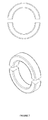
- FIG. 7 Exploded View of Neodymium Permanent Magnet Ring
- FIG. 8 Control Units
- FIG. 9 Battery
- the invention consists of endovascular apparatus ( 1 ), extravascular apparatus ( 2 ), control units ( 3 ), batteries ( 4 ) and protective cover ( 5 ) fragments.
- Endovascular apparatus ( 1 ) are composed of an engine ( 1 . 1 ), a rotor ( 1 . 2 ), helical propellers ( 1 . 3 ), a magnetic bearing ( 1 . 4 ), a texture cage skeleton ( 1 . 5 ), permanent neodymium magnet bars ( 1 . 6 ), permanent neodymium magnet rings ( 1 . 7 ) and pressure sensors ( 1 . 8 ).
- Extravascular apparatus ( 2 ) consists of a stator ( 2 . 1 ) and electrical coils ( 2 . 2 ).
- Control units ( 3 ) contain an internal control unit ( 3 . 1 ), an external control unit ( 3 . 2 ), a touch screen ( 3 . 3 ) and microprocessor ( 3 . 4 ) units.
- the batteries providing the electrical energy requirement of the system ( 4 ) includes an internal battery ( 4 . 1 ), an external battery ( 4 . 2 ), power transmission apparatus ( 4 . 3 ) and electric power cables ( 4 . 4 ).
- the protective cover ( 5 ) made of bio-compatible materials that provide protection of apparatus placed into the body, comprises of an ECG connector ( 5 . 1 ) providing data transfer to the internal control unit.
- the rotor ( 1 . 2 ) is in the vessel and the stator ( 2 . 1 ) is located outside the vessel, the rotor ( 1 . 2 ) containing helical propellers ( 1 . 3 ) is located in the artery and rotates without contacting the artery on magnetic bearing ( 1 . 4 ).
- Texture endovascular skeletal cage ( 1 . 5 ) is for supporting rotation field of the rotor.
- Magnetic bearing ( 1 . 4 ) formed with the help of permanent Neodymium magnet bars ( 1 . 0 and permanent neodymium magnet rings ( 1 . 7 ) are fixed onto this texture skeletal cage.
- Stators ( 2 . 1 ) are made from overlapped sheets of silicium tin, and there are cavities on it and the coils ( 2 . 2 ) of the electric motor are fixed in the cavities.
- the rotor, one of the endovascular apparatus attachment, ( 1 . 2 ) is hollow and includes at least two helical fins on the iron skeleton ( 1 . 3 ).
- propellers open when the rotor rotates quickly, and provides propulsion and becomes parallel to the inner surface of the rotor when it stops and empties the vessel lumen.
- heart disease heals after a period of time or the rotor stops because of technical reasons, propellers will not constitute an obstacle to the artery blood flow.
- heart assist device will remain connected to the patient's heart until his death and will run and continue to support the heart.
- the speed of the rotor rotation will be adjusted by the microprocessor ( 3 . 4 ), with the synchronized analysis of the ECG signals in real time, and it will increase or decrease along with them.
- the pre-determined and recorded rotation speed of the engine by the doctor according to the patient's condition will be selected and implemented by the microprocessor ( 3 . 4 ) automatically.
- the pre-determined and recorded rotation speed of the engine by the doctor according to the patient's condition will be selected and implemented by the microprocessor ( 3 . 4 ) automatically.
- Blood pressure will be monitored nonstop with the pressure sensors ( 1 . 8 ) and the data obtained with the artificial intelligence will be processed and optimal rotor speed will be determined with the help of software. There will be settings menu including pre-determined upper and lower limits of rotor speeds.
- Pressure sensors ( 1 . 8 ) are also supplied into the artery and blood pressure values will be processed by the artificial intelligence in real-time and then the rotor speed will be increased or decreased by the microprocessor ( 3 . 4 ).
- Permanent neodymium magnet rings ( 1 . 7 ) have been placed outside the vessel. Thanks to the magnetic field produced by the permanent neodymium magnet rings ( 1 . 7 ) on either side of both the stator and the rotor, it has been provided to run the rotor and stator safely in their location.
- stator and permanent neodymium rings ( 1 . 7 ) consist of at least two parts.
- a heart surgeon can install them as a single piece by wrapping them around the artery like a clamp and assembling them before cutting the pulmonary aorta completely.
- endovascular apparatus ( 1 ) In order to facilitate the coverage of endovascular apparatus ( 1 ) as a result of intimal proliferation, perforated, durable and bio-compatible wire woven texture cage skeleton ( 1 . 5 ) has been placed into the vein. Other endovascular apparatus ( 1 ) are fixed on the texture cage skeleton ( 1 . 5 ).
- Apparatus placed into the artery are applied without damaging the patient's heart and vascular physiology.
- Heart surgeon places the system properly into the artery through a small incision and then the cut is repaired with a proper technique, and the artery remains intact.
- This heart assist device will provide the patient pulsatile blood flow by running or slowing synchronized with the electrocardiogram (ECG) signals received from the patient.
- ECG electrocardiogram
Landscapes
- Health & Medical Sciences (AREA)
- Heart & Thoracic Surgery (AREA)
- Engineering & Computer Science (AREA)
- Life Sciences & Earth Sciences (AREA)
- General Health & Medical Sciences (AREA)
- Anesthesiology (AREA)
- Biomedical Technology (AREA)
- Hematology (AREA)
- Cardiology (AREA)
- Animal Behavior & Ethology (AREA)
- Mechanical Engineering (AREA)
- Public Health (AREA)
- Veterinary Medicine (AREA)
- Vascular Medicine (AREA)
- Transplantation (AREA)
- Medical Informatics (AREA)
- External Artificial Organs (AREA)
- Prostheses (AREA)
Abstract
The invention is a next generation miniature heart assist device developed in order to maintain the blood circulation in patients with severe heart failure, and is applied endovascularly to the large arteries. This device is technically a kind of synchronous servo electric motor using “direct drive technology”. It provides longer battery life and high blood flow. Small volume and very low energy consumption provide a much longer battery life and a high blood flow. As the outer surface of the parts placed into the blood vessel will be completely covered with the endothelial cells and the intima layer of the arteries in time, there will be no foreign surface contacting directly with blood. As a result, no thromboembolic event or any negative effect on the cellular components of blood is expected.
Description
The invention is a next generation miniature heart assist device which has been developed in order to maintain the blood circulation in patients with severe heart failure, and is applied endovascularly to the large arteries such as the assending aorta and the pulmonary arteries.
Heart assist devices are vital devices in heart diseases when heart muscle contractions are insufficient, and there is no respond to medications. Nowadays, due to coronary heart diseases and myokardial infarcts (it is the formation of necrosis as a result of blockage of a coronary artery), tens of thousands of people receive the treatment of heart failure. When the drug treatment is insufficient, a heart transplant becomes necessary. Since finding a donor for a heart transplant is not very easy, heart assist devices kept ready for emergency use have become life-saving. In addition, some heart diseases may lead to heart failure even in newborn infants. For this reason, heart assist devices should be produced in all sizes, including pediatric sizes.
In order to ensure a high quality of life for the heart patients waiting for donor's heart, a number of studies to improve heart assist devices have been made and many different products have been presented to the physicians. Jarvik 2000, Lionheart, Coraide, HeartMate II (Thoratec Corp), Berlin heart and HeartSaver are some of these main products. The latest generation device in this area is DeBakey Heart assist device that has been developed with the help of NASA engineers in the United States by Micormed Company representing new generation devices. The fact that they are small in size and suitable for all ages have made these devices the most ideal for today. As it also requires a less invasive surgical procedure, today, it is preferred by cardiac surgeons as for the patients.
Balloon pumps inserted into the aorta were used for this purpose in the past. It was intended that the balloon inflating and deflating synchronously with the heart would provide additional acceleration to the blood flow in the aorta. Later, air-driven systems have been developed. Compressed air is provided from the compressor and air tank moving with the patient. By moving back and forth when the compressed air inflates and deflates, the membrane produces a power propelling the blood. After a while, electric motor systems have been developed, and these systems were first designed with an electric motor and a snail water turbine adapted to it. There are artificial blood vessels (conduits) entering and leaving the system. One end of vessel is placed into the heart and the other end into the aortic artery, and when the engine runs, it takes blood from the heart and pumps out into the aorta.
Compressed air systems were annoying as they run loudly. Because the efficiency of the engine was low and the engine volume was large in electric motor systems, it was a problem to install it into the patients. Moreover, considering them as high-energy-consuming systems, they significantly restricted the ability of the patients to move.
It is a heart assist device which is installed endovascularly to one of the large arteries such as the aorta (assending aorta) or the pulmonary arteries, and it is helpful to maintain the blood circulation in patients with severe heart failure. The rotor without rotating shaft provides adequate blood flow propelling the blood with its helical propellers.
This is a device with a rotor which rotates with the heart's contraction (systole) and stops or slows simultaneously during, the relaxation (diastole) period, and this is a next generation miniature endovascular heart assist device which contains a sort of synchronous servo electric motor using “direct drive technology”. When compared with its counterparts in its field, it is presented as a different concept with new and outstanding features.
As a result of the proliferation of the intima layer of the arteries that is the innermost layer of veins, and covering the endothelial cells coating the inside of vessels, the outer surface of the parts placed into a blood vessel will be completely covered in a few months. Thus, the foreign surface contacting with blood will be only a rotating rotor and its helical propellers. Consequently, there will be no thromboembolic event or any negative effect on the cellular components of blood.
The device, which consumes less energy and provides longer battery life than its counterparts and with its small volume, extraordinary design and endovascular placement, is an endovascular heart assist device that is small enough to be inserted into a large artery.
The equivalents of part numerals described in the figures are given below;
1. Endovascular apparatus
-
- 1.1. Motor
- 1.2. Rotor
- 1.3. Helical Propeller
- 1.4. Magnetic bearing
- 1.5. Texture cage skeleton
- 1.6. Permanent Neodymium Magnet Bar
- 1.7. Permanent Neodymium Magnet Ring
- 1.8, Pressure Sensors
2. Endovascular Apparatus.
-
- 2.1. Stator
- 2.2. Electric coils
3. Control Units
-
- 3.1. Internal Control Unit
- 3.2. External Control Unit
- 3.3. Touch Screen
- 3.4, Microprocessor
4. Batteries
-
- 4.1. Internal Battery
- 4.2. External Battery
- 4.3, Power Transmission Apparatus
- 4.4, Electrical Power Cable
5. Protective Case
-
- 5.1. ECG Connection
The invention consists of endovascular apparatus (1), extravascular apparatus (2), control units (3), batteries (4) and protective cover (5) fragments. Endovascular apparatus (1) are composed of an engine (1.1), a rotor (1.2), helical propellers (1.3), a magnetic bearing (1.4), a texture cage skeleton (1.5), permanent neodymium magnet bars (1.6), permanent neodymium magnet rings (1.7) and pressure sensors (1.8). Extravascular apparatus (2) consists of a stator (2.1) and electrical coils (2.2). Control units (3) contain an internal control unit (3.1), an external control unit (3.2), a touch screen (3.3) and microprocessor (3.4) units. The batteries providing the electrical energy requirement of the system (4) includes an internal battery (4.1), an external battery (4.2), power transmission apparatus (4.3) and electric power cables (4.4). The protective cover (5) made of bio-compatible materials that provide protection of apparatus placed into the body, comprises of an ECG connector (5.1) providing data transfer to the internal control unit.
In order to install the heart assist device to the artery as we mentioned about it in the national patent application numbered TR2012/00951 and Patent Cooperation Treaty application numbered PCT/TR2012/00055 we made before, as can be understood from documents, the artery is cut completely from a certain place, and either side of the two cuts is stitched transarterially to the input and output section of the heart assist device. When the documents are examined, it will occur that this device is too large to be placed in the vessel as well as a one-piece integral with the rotor and stator.
However, in the endovascular heart assist device, the subject of this invention, the rotor (1.2) is in the vessel and the stator (2.1) is located outside the vessel, the rotor (1.2) containing helical propellers (1.3) is located in the artery and rotates without contacting the artery on magnetic bearing (1.4). Texture endovascular skeletal cage (1.5) is for supporting rotation field of the rotor. Magnetic bearing (1.4) formed with the help of permanent Neodymium magnet bars (1.0 and permanent neodymium magnet rings (1.7) are fixed onto this texture skeletal cage. The circular power that rotates the rotor in the magnetic field is generated by the current passing through the coils on the stator (2.1) outside the artery. Stators (2.1) are made from overlapped sheets of silicium tin, and there are cavities on it and the coils (2.2) of the electric motor are fixed in the cavities.
The rotor, one of the endovascular apparatus attachment, (1.2) is hollow and includes at least two helical fins on the iron skeleton (1.3). As the points where propellers are attached to the rotor are flexible and foldable, propellers open when the rotor rotates quickly, and provides propulsion and becomes parallel to the inner surface of the rotor when it stops and empties the vessel lumen. Thus, if heart disease heals after a period of time or the rotor stops because of technical reasons, propellers will not constitute an obstacle to the artery blood flow.
If the patient's heart does not heal, then heart assist device will remain connected to the patient's heart until his death and will run and continue to support the heart. The speed of the rotor rotation will be adjusted by the microprocessor (3.4), with the synchronized analysis of the ECG signals in real time, and it will increase or decrease along with them. When the ECG signals are not received, the pre-determined and recorded rotation speed of the engine by the doctor according to the patient's condition will be selected and implemented by the microprocessor (3.4) automatically. When the ECG signals are not technically feasible, there are intense parasites or in case of irregular heart rhythm, (arrhythmia, irregular heartbeat, too fast or too slow heart beats, etc.), the pre-determined and recorded rotation speed of the engine by the doctor according to the patient's condition will be selected and implemented by the microprocessor (3.4) automatically.
Blood pressure will be monitored nonstop with the pressure sensors (1.8) and the data obtained with the artificial intelligence will be processed and optimal rotor speed will be determined with the help of software. There will be settings menu including pre-determined upper and lower limits of rotor speeds.
Pressure sensors (1.8) are also supplied into the artery and blood pressure values will be processed by the artificial intelligence in real-time and then the rotor speed will be increased or decreased by the microprocessor (3.4).
Permanent neodymium magnet rings (1.7) have been placed outside the vessel. Thanks to the magnetic field produced by the permanent neodymium magnet rings (1.7) on either side of both the stator and the rotor, it has been provided to run the rotor and stator safely in their location.
The stator and permanent neodymium rings (1.7) consist of at least two parts. Thus, a heart surgeon can install them as a single piece by wrapping them around the artery like a clamp and assembling them before cutting the pulmonary aorta completely.
In order to facilitate the coverage of endovascular apparatus (1) as a result of intimal proliferation, perforated, durable and bio-compatible wire woven texture cage skeleton (1.5) has been placed into the vein. Other endovascular apparatus (1) are fixed on the texture cage skeleton (1.5).
It is known that the outside of the devices made of nickel-titanium alloy (nitiIon) like a stent and septal occlude is covered by the intima layer and vascular endothelial cells about 6-8 weeks after the placement of the devices. It is estimated that the apparatus (1) of our invention will also be covered naturally with the intima layer and vascular endothelial cells as a result of intimal proliferation. Thus, the contacting surface of blood with foreign material would be limited to only the surface of the spinning rotor, and this would not damage the cellular components of blood.
Apparatus placed into the artery are applied without damaging the patient's heart and vascular physiology. Heart surgeon places the system properly into the artery through a small incision and then the cut is repaired with a proper technique, and the artery remains intact. This heart assist device will provide the patient pulsatile blood flow by running or slowing synchronized with the electrocardiogram (ECG) signals received from the patient. As we know, an individual has a pulsatile blood flow and pulsatile blood flow has many advantages in perfusion the tissues when compared with continuous blood flow.
Claims (16)
1. A heart assist device, comprising:
an endovascular apparatus configured to be surgically placed into great arteries; wherein the endovascular apparatus comprises a rotor, which is the rotating part of as motor; wherein the rotor is hollow with at least two helical propellers attached to its inner surface;
a non-vascular apparatus configured to be surgically placed outside the great arteries; and
a protective cover configured to provide protection for the endovascular apparatus and the nonvascular apparatus;
wherein the endovascular apparatus further comprises:
a magnetic bearing;
a plurality of pressure sensors; and
a texture cage skeleton;
wherein the magnetic bearing further comprises a plurality of first permanent neodymium magnet rings in front of and behind the rotor and a plurality of permanent neodymium magnet bars; wherein the permanent neodymium magnet bars are located on the outer surface of the rotor;
the endovascular apparatus is assembled;
the texture cage skeleton is made of texture, braided, resistant and bio-compatible material that enhances covering of intimal proliferation.
2. A heart assist device, comprising:
an endovascular apparatus configured to be surgically placed into great arteries; wherein the endovascular apparatus comprises a rotor, which is the rotating part of a motor; wherein the rotor is hollow with at least two helical propellers attached to its inner surface;
a non-vascular apparatus configured to be surgically placed outside the great arteries; and
a protective cover configured to provide protection for the endovascular apparatus and the nonvascular apparatus;
wherein the endovascular apparatus further comprises:
a magnetic bearing;
a plurality of pressure sensors; and
a texture cage skeleton;
wherein the magnetic bearing further comprises a plurality of first permanent neodymium magnet rings in front of and behind the rotor and a plurality of permanent neodymium magnet bars; wherein the permanent neodymium magnet bars are located on the outer surface of the rotor;
the endovascular apparatus is assembled;
the points where the helical propellers are attached to the rotor are flexible and foldable so that the helical propellers are capable of being parallel to the inner surface of the rotor.
3. The heart assist device according to claim 2 , wherein the helical propellers open when the rotor rotates quickly, and provides propulsion, and becomes parallel to the inner surface of the rotor when the rotor stops.
4. A heart assist device, comprising:
an endovascular apparatus configured to be surgically placed into great arteries; wherein the endovascular apparatus comprises a rotor, which is the rotating part of a motor; wherein the rotor is hollow with at least two helical propellers attached to its inner surface;
a non-vascular apparatus configured to be surgically placed outside the great arteries; and
a protective cover configured to provide protection for the endovascular apparatus and the nonvascular apparatus;
wherein the endovascular apparatus further comprises:
a magnetic bearing;
a plurality of pressure sensors; and
a texture cage skeleton:
wherein the magnetic bearing further comprises a plurality of first permanent neodymium magnet rings in front of and behind the rotor and a plurality of permanent neodymium magnet bars; wherein the permanent neodymium magnet bars are located on the outer surface of the rotor;
the endovascular apparatus is assembled;
the points where the helical propellers are attached to the rotor are angular to the axis of a vessel in order to provide propulsion in the blood stream while rotating rapidly.
5. The heart assist device according to claim 4 , wherein the helical propellers are characterized by the fact that if the rotor stops because of technical reasons, the tips of helical propellers remain parallel to the axis of the vessel so as not to constitute a serious obstacle in front of the hearts left ventricle.
6. The heart assist device according to claim 4 , wherein the non-vascular apparatus further comprises a stator, which is a motionless part of the motor; a plurality of electric motor coils; and a plurality of second permanent magnet rings on either sides of the stator, and the stator is made of overlapped sheets of silicium tin.
7. The heart assist device according claim 6 , wherein an electric current transferred to the electric motor coils existing in the stator. the permanent neodymium magnet bars on the rotor and the part standing in a space without friction in the magnetic bearing-is created by the second permanent magnet rings located on both sides of the stator and the rotor and operating without friction while rotating.
8. The heart assist device according claim 4 , wherein the texture cage skeleton is made of material with magnetic property, wherein the rotor, the helical propellers, and the magnetic bearing are contained within the texture cage skeleton.
9. The heart assist device according to claim 8 . wherein the magnetic bearing is characterized by the permanent neodymium magnet ring that causes propulsion by positioning the same poles facing opposite each other, the permanent neodymium magnet bars-located on the rotor.
10. The heart assist device according to claim 4 , wherein the motor is characterized by the three-phase, synchronous servo-motor and runs with low-volt alternating current.
11. The heart assist device according to claim 4 , wherein the heart assist device further comprises:
a plurality of control units configured to control the heart assist device;
a plurality of batteries configured to supply electrical energy to the heart assist device;
wherein the control unit comprises an internal control unit, an external control unit, a touch screen; wherein the internal control unit further comprises a microprocessor;
wherein the battery comprises an internal, an external battery, a power transmission apparatus, and a plurality of electric power cables;
wherein the protective cover comprises an ECG connector for providing data transfer to the e internal control unit.
12. The heart assist device according to claim 11 , wherein the rotational speed of the rotor is adjusted according to synchronous signals received from an ECG link, synchronous signals received from the plurality of pressure sensors and the part controlled by the microprocessor according to the settings determined by physicians.
13. The heart assist device according to claim 12 , wherein when the synchronous signals from the pressure sensors to the ECG link are not received or the synchronous signals are not technically feasible or in case of irregular heart rhythm, rotation speed of the rotor is controlled by the microprocessor according to a patient-specific pre-determined adjustment made by the physicians.
14. The heart assist device according to claim 13 , wherein the pressure sensors measure the arterial blood pressure in real time.
15. The heart assist device according to claim 6 , wherein the stator further comprises a plurality of cavities, and the plurality of electric motor coils are fixed in the cavities.
16. The heart assist device according to claim 4 , wherein comers of the endovascular apparatus are radius so that blood clots cannot develop on the surfaces of the corners.
Applications Claiming Priority (3)
| Application Number | Priority Date | Filing Date | Title |
|---|---|---|---|
| TR2012/07222A TR201207222A2 (en) | 2012-06-21 | 2012-06-21 | Intravenous heart support device. |
| TR2012/07222 | 2012-06-21 | ||
| PCT/TR2013/000181 WO2013191667A1 (en) | 2012-06-21 | 2013-06-13 | Endovascular heart assist device |
Publications (2)
| Publication Number | Publication Date |
|---|---|
| US20150190561A1 US20150190561A1 (en) | 2015-07-09 |
| US9555175B2 true US9555175B2 (en) | 2017-01-31 |
Family
ID=47680630
Family Applications (1)
| Application Number | Title | Priority Date | Filing Date |
|---|---|---|---|
| US14/410,110 Active US9555175B2 (en) | 2012-06-21 | 2013-06-13 | Endovascular heart assist device |
Country Status (3)
| Country | Link |
|---|---|
| US (1) | US9555175B2 (en) |
| TR (1) | TR201207222A2 (en) |
| WO (1) | WO2013191667A1 (en) |
Cited By (44)
| Publication number | Priority date | Publication date | Assignee | Title |
|---|---|---|---|---|
| WO2018067410A1 (en) | 2016-10-03 | 2018-04-12 | Queen Mary University Of London | Mechanical circulatory support device with axial flow turbomachine optimized for heart failure and cardio-renal syndrome |
| WO2018223060A1 (en) | 2017-06-01 | 2018-12-06 | Queen Mary University Of London | Mechanical circulatory support device with centrifugal impeller designed for implantation in the descending aorta |
| WO2019195480A1 (en) | 2018-04-04 | 2019-10-10 | Theodosios Korakianitis | Removable mechanical circulatory support for short term use |
| US10722631B2 (en) | 2018-02-01 | 2020-07-28 | Shifamed Holdings, Llc | Intravascular blood pumps and methods of use and manufacture |
| US11185677B2 (en) | 2017-06-07 | 2021-11-30 | Shifamed Holdings, Llc | Intravascular fluid movement devices, systems, and methods of use |
| US11368081B2 (en) | 2018-01-24 | 2022-06-21 | Kardion Gmbh | Magnetic coupling element with a magnetic bearing function |
| US11511103B2 (en) | 2017-11-13 | 2022-11-29 | Shifamed Holdings, Llc | Intravascular fluid movement devices, systems, and methods of use |
| US11654275B2 (en) | 2019-07-22 | 2023-05-23 | Shifamed Holdings, Llc | Intravascular blood pumps with struts and methods of use and manufacture |
| US11724089B2 (en) | 2019-09-25 | 2023-08-15 | Shifamed Holdings, Llc | Intravascular blood pump systems and methods of use and control thereof |
| US11754075B2 (en) | 2018-07-10 | 2023-09-12 | Kardion Gmbh | Impeller for an implantable, vascular support system |
| US11944805B2 (en) | 2020-01-31 | 2024-04-02 | Kardion Gmbh | Pump for delivering a fluid and method of manufacturing a pump |
| US11964145B2 (en) | 2019-07-12 | 2024-04-23 | Shifamed Holdings, Llc | Intravascular blood pumps and methods of manufacture and use |
| US12005248B2 (en) | 2018-05-16 | 2024-06-11 | Kardion Gmbh | Rotor bearing system |
| US12064615B2 (en) | 2018-05-30 | 2024-08-20 | Kardion Gmbh | Axial-flow pump for a ventricular assist device and method for producing an axial-flow pump for a ventricular assist device |
| US12076549B2 (en) | 2018-07-20 | 2024-09-03 | Kardion Gmbh | Feed line for a pump unit of a cardiac assistance system, cardiac assistance system and method for producing a feed line for a pump unit of a cardiac assistance system |
| US12107474B2 (en) | 2018-05-16 | 2024-10-01 | Kardion Gmbh | End-face rotating joint for transmitting torques |
| US12102815B2 (en) | 2019-09-25 | 2024-10-01 | Shifamed Holdings, Llc | Catheter blood pumps and collapsible pump housings |
| US12121713B2 (en) | 2019-09-25 | 2024-10-22 | Shifamed Holdings, Llc | Catheter blood pumps and collapsible blood conduits |
| US12144976B2 (en) | 2018-06-21 | 2024-11-19 | Kardion Gmbh | Method and device for detecting a wear condition of a ventricular assist device and for operating same, and ventricular assist device |
| US12161857B2 (en) | 2018-07-31 | 2024-12-10 | Shifamed Holdings, Llc | Intravascular blood pumps and methods of use |
| US12178554B2 (en) | 2018-06-06 | 2024-12-31 | Kardion Gmbh | Systems and methods for determining a viscosity of a fluid |
| US12194287B2 (en) | 2018-05-30 | 2025-01-14 | Kardion Gmbh | Method of manufacturing electrical conductor tracks in a region of an intravascular blood pump |
| US12201821B2 (en) | 2018-06-06 | 2025-01-21 | Kardion Gmbh | Method for determining a flow rate of a fluid flowing through an implanted vascular support system, and implantable vascular support system |
| US12201823B2 (en) | 2018-05-30 | 2025-01-21 | Kardion Gmbh | Line device for conducting a blood flow for a heart support system, heart support system, and method for producing a line device |
| US12220570B2 (en) | 2018-10-05 | 2025-02-11 | Shifamed Holdings, Llc | Intravascular blood pumps and methods of use |
| US12222267B2 (en) | 2018-06-06 | 2025-02-11 | Kardion Gmbh | Analysis device and method for analyzing a viscosity of a fluid |
| US12257424B2 (en) | 2018-06-06 | 2025-03-25 | Kardion Gmbh | Implantable ventricular assist system and method for operating same |
| US12263333B2 (en) | 2018-06-21 | 2025-04-01 | Kardion Gmbh | Stator vane device for guiding the flow of a fluid flowing out of an outlet opening of a ventricular assist device, ventricular assist device with stator vane device, method for operating a stator vane device and manufacturing method |
| US12311160B2 (en) | 2018-06-06 | 2025-05-27 | Kardion Gmbh | Method and system for determining the speed of sound in a fluid in the region of a cardiac support system |
| US12310708B2 (en) | 2018-06-06 | 2025-05-27 | Kardion Gmbh | Systems and methods for determining a flow speed of a fluid flowing through a cardiac assist device |
| US12324906B2 (en) | 2018-06-06 | 2025-06-10 | Kardion Gmbh | Systems and methods for determining a total blood volume flow in a cardiac support system and vascular support system |
| US12377256B2 (en) | 2018-06-06 | 2025-08-05 | Kardion Gmbh | Cardiac support system flow measurement using pressure sensors |
| US12383727B2 (en) | 2018-05-30 | 2025-08-12 | Kardion Gmbh | Motor housing module for a heart support system, and heart support system and method for mounting a heart support system |
| US12390633B2 (en) | 2018-08-07 | 2025-08-19 | Kardion Gmbh | Bearing device for a heart support system, and method for rinsing a space in a bearing device for a heart support system |
| US12409310B2 (en) | 2019-12-11 | 2025-09-09 | Shifamed Holdings, Llc | Descending aorta and vena cava blood pumps |
| US12447327B2 (en) | 2018-05-30 | 2025-10-21 | Kardion Gmbh | Electronics module and arrangement for a ventricular assist device, and method for producing a ventricular assist device |
| US12465748B2 (en) | 2019-08-07 | 2025-11-11 | Supira Medical, Inc. | Catheter blood pumps and collapsible pump housings |
| US12465744B2 (en) | 2018-07-10 | 2025-11-11 | Kardion Gmbh | Impeller housing for an implantable, vascular support system |
| US12478775B2 (en) | 2018-07-09 | 2025-11-25 | Kardion Gmbh | Cardiac assist system, and method for monitoring the integrity of a retaining structure of a cardiac assist system |
| US12478267B2 (en) | 2018-06-06 | 2025-11-25 | Kardion Gmbh | Sensor head device for a minimal invasive ventricular assist device and method for producing such a sensor head device |
| US12491357B2 (en) | 2018-06-06 | 2025-12-09 | Kardion Gmbh | Systems and methods for determining a blood volume flow through a cardiac support system and vascular support system |
| US12502524B2 (en) | 2021-12-03 | 2025-12-23 | Kardion Gmbh | Cardiac pump with optical fiber for laser doppler |
| US12508418B2 (en) | 2018-08-08 | 2025-12-30 | Kardion Gmbh | Device and method for monitoring the state of health of a patient |
| US12515036B2 (en) | 2020-09-14 | 2026-01-06 | Kardion Gmbh | Cardiovascular support pump having an impeller with a variable flow area |
Families Citing this family (7)
| Publication number | Priority date | Publication date | Assignee | Title |
|---|---|---|---|---|
| EP2942527B1 (en) * | 2013-01-07 | 2018-04-11 | National University Corporation Kobe University | Axial flow blood pump |
| WO2014120101A2 (en) | 2013-01-29 | 2014-08-07 | Bulent Oran | Permanent total artificial heart device |
| US11759186B2 (en) * | 2018-06-08 | 2023-09-19 | David S. Goldsmith | Ductus side-entry and prosthetic disorder response systems |
| EP3313471A4 (en) | 2015-06-29 | 2019-02-20 | Tc1 Llc | Ventricular assist devices having a hollow rotor and methods of use |
| DE102017212193A1 (en) * | 2017-07-17 | 2019-01-17 | Robert Bosch Gmbh | A rotor assembly for a cardiac assist system and method of manufacturing a rotor assembly for a cardiac assist system |
| CN112075942A (en) * | 2020-07-03 | 2020-12-15 | 黑龙江仁芯众康生物科技有限公司 | Nanometer biological detector for noninvasive evaluation of stability of arteriosclerotic plaque |
| CN112316297A (en) * | 2020-11-03 | 2021-02-05 | 四川大学华西医院 | Hollow heart auxiliary pump |
Citations (6)
| Publication number | Priority date | Publication date | Assignee | Title |
|---|---|---|---|---|
| US5527159A (en) * | 1993-11-10 | 1996-06-18 | The United States Of America As Represented By The Administrator Of The National Aeronautics And Space Administration | Rotary blood pump |
| WO2003015609A2 (en) | 2001-08-16 | 2003-02-27 | Apex Medical, Inc. | Physiological heart pump control |
| US20040215050A1 (en) | 2002-01-07 | 2004-10-28 | Micromed Technology, Inc. | Blood pump system and method of operation |
| WO2008135988A2 (en) | 2007-05-03 | 2008-11-13 | Leviticus-Cardio Ltd. | Permanent ventricular assist device for treating heart failure |
| WO2010042008A1 (en) | 2008-10-10 | 2010-04-15 | Milux Holding Sa | Heart help pump, system, and method |
| EP2194278A1 (en) | 2008-12-05 | 2010-06-09 | ECP Entwicklungsgesellschaft mbH | Fluid pump with a rotor |
-
2012
- 2012-06-21 TR TR2012/07222A patent/TR201207222A2/en unknown
-
2013
- 2013-06-13 US US14/410,110 patent/US9555175B2/en active Active
- 2013-06-13 WO PCT/TR2013/000181 patent/WO2013191667A1/en not_active Ceased
Patent Citations (8)
| Publication number | Priority date | Publication date | Assignee | Title |
|---|---|---|---|---|
| US5527159A (en) * | 1993-11-10 | 1996-06-18 | The United States Of America As Represented By The Administrator Of The National Aeronautics And Space Administration | Rotary blood pump |
| WO2003015609A2 (en) | 2001-08-16 | 2003-02-27 | Apex Medical, Inc. | Physiological heart pump control |
| US20040215050A1 (en) | 2002-01-07 | 2004-10-28 | Micromed Technology, Inc. | Blood pump system and method of operation |
| WO2008135988A2 (en) | 2007-05-03 | 2008-11-13 | Leviticus-Cardio Ltd. | Permanent ventricular assist device for treating heart failure |
| US20100076247A1 (en) * | 2007-05-03 | 2010-03-25 | Leviticus-Cardio Ltd. | Permanent ventricular assist device for treating heart failure |
| WO2010042008A1 (en) | 2008-10-10 | 2010-04-15 | Milux Holding Sa | Heart help pump, system, and method |
| EP2194278A1 (en) | 2008-12-05 | 2010-06-09 | ECP Entwicklungsgesellschaft mbH | Fluid pump with a rotor |
| US20110275884A1 (en) * | 2008-12-05 | 2011-11-10 | Ecp Entwicklungsgesellschaft Mbh | Fluid pump with a rotor |
Cited By (50)
| Publication number | Priority date | Publication date | Assignee | Title |
|---|---|---|---|---|
| WO2018067410A1 (en) | 2016-10-03 | 2018-04-12 | Queen Mary University Of London | Mechanical circulatory support device with axial flow turbomachine optimized for heart failure and cardio-renal syndrome |
| WO2018223060A1 (en) | 2017-06-01 | 2018-12-06 | Queen Mary University Of London | Mechanical circulatory support device with centrifugal impeller designed for implantation in the descending aorta |
| US11717670B2 (en) | 2017-06-07 | 2023-08-08 | Shifamed Holdings, LLP | Intravascular fluid movement devices, systems, and methods of use |
| US11185677B2 (en) | 2017-06-07 | 2021-11-30 | Shifamed Holdings, Llc | Intravascular fluid movement devices, systems, and methods of use |
| US11511103B2 (en) | 2017-11-13 | 2022-11-29 | Shifamed Holdings, Llc | Intravascular fluid movement devices, systems, and methods of use |
| US11804767B2 (en) | 2018-01-24 | 2023-10-31 | Kardion Gmbh | Magnetic coupling element with a magnetic bearing function |
| US11368081B2 (en) | 2018-01-24 | 2022-06-21 | Kardion Gmbh | Magnetic coupling element with a magnetic bearing function |
| US11229784B2 (en) | 2018-02-01 | 2022-01-25 | Shifamed Holdings, Llc | Intravascular blood pumps and methods of use and manufacture |
| US10722631B2 (en) | 2018-02-01 | 2020-07-28 | Shifamed Holdings, Llc | Intravascular blood pumps and methods of use and manufacture |
| US12076545B2 (en) | 2018-02-01 | 2024-09-03 | Shifamed Holdings, Llc | Intravascular blood pumps and methods of use and manufacture |
| WO2019195480A1 (en) | 2018-04-04 | 2019-10-10 | Theodosios Korakianitis | Removable mechanical circulatory support for short term use |
| US12107474B2 (en) | 2018-05-16 | 2024-10-01 | Kardion Gmbh | End-face rotating joint for transmitting torques |
| US12005248B2 (en) | 2018-05-16 | 2024-06-11 | Kardion Gmbh | Rotor bearing system |
| US12447327B2 (en) | 2018-05-30 | 2025-10-21 | Kardion Gmbh | Electronics module and arrangement for a ventricular assist device, and method for producing a ventricular assist device |
| US12383727B2 (en) | 2018-05-30 | 2025-08-12 | Kardion Gmbh | Motor housing module for a heart support system, and heart support system and method for mounting a heart support system |
| US12201823B2 (en) | 2018-05-30 | 2025-01-21 | Kardion Gmbh | Line device for conducting a blood flow for a heart support system, heart support system, and method for producing a line device |
| US12194287B2 (en) | 2018-05-30 | 2025-01-14 | Kardion Gmbh | Method of manufacturing electrical conductor tracks in a region of an intravascular blood pump |
| US12064615B2 (en) | 2018-05-30 | 2024-08-20 | Kardion Gmbh | Axial-flow pump for a ventricular assist device and method for producing an axial-flow pump for a ventricular assist device |
| US12377256B2 (en) | 2018-06-06 | 2025-08-05 | Kardion Gmbh | Cardiac support system flow measurement using pressure sensors |
| US12310708B2 (en) | 2018-06-06 | 2025-05-27 | Kardion Gmbh | Systems and methods for determining a flow speed of a fluid flowing through a cardiac assist device |
| US12491357B2 (en) | 2018-06-06 | 2025-12-09 | Kardion Gmbh | Systems and methods for determining a blood volume flow through a cardiac support system and vascular support system |
| US12478267B2 (en) | 2018-06-06 | 2025-11-25 | Kardion Gmbh | Sensor head device for a minimal invasive ventricular assist device and method for producing such a sensor head device |
| US12324906B2 (en) | 2018-06-06 | 2025-06-10 | Kardion Gmbh | Systems and methods for determining a total blood volume flow in a cardiac support system and vascular support system |
| US12311160B2 (en) | 2018-06-06 | 2025-05-27 | Kardion Gmbh | Method and system for determining the speed of sound in a fluid in the region of a cardiac support system |
| US12178554B2 (en) | 2018-06-06 | 2024-12-31 | Kardion Gmbh | Systems and methods for determining a viscosity of a fluid |
| US12257424B2 (en) | 2018-06-06 | 2025-03-25 | Kardion Gmbh | Implantable ventricular assist system and method for operating same |
| US12201821B2 (en) | 2018-06-06 | 2025-01-21 | Kardion Gmbh | Method for determining a flow rate of a fluid flowing through an implanted vascular support system, and implantable vascular support system |
| US12222267B2 (en) | 2018-06-06 | 2025-02-11 | Kardion Gmbh | Analysis device and method for analyzing a viscosity of a fluid |
| US12144976B2 (en) | 2018-06-21 | 2024-11-19 | Kardion Gmbh | Method and device for detecting a wear condition of a ventricular assist device and for operating same, and ventricular assist device |
| US12263333B2 (en) | 2018-06-21 | 2025-04-01 | Kardion Gmbh | Stator vane device for guiding the flow of a fluid flowing out of an outlet opening of a ventricular assist device, ventricular assist device with stator vane device, method for operating a stator vane device and manufacturing method |
| US12478775B2 (en) | 2018-07-09 | 2025-11-25 | Kardion Gmbh | Cardiac assist system, and method for monitoring the integrity of a retaining structure of a cardiac assist system |
| US12523228B2 (en) | 2018-07-10 | 2026-01-13 | Kardion Gmbh | Impeller for an implantable, vascular support system |
| US12465744B2 (en) | 2018-07-10 | 2025-11-11 | Kardion Gmbh | Impeller housing for an implantable, vascular support system |
| US11754075B2 (en) | 2018-07-10 | 2023-09-12 | Kardion Gmbh | Impeller for an implantable, vascular support system |
| US12076549B2 (en) | 2018-07-20 | 2024-09-03 | Kardion Gmbh | Feed line for a pump unit of a cardiac assistance system, cardiac assistance system and method for producing a feed line for a pump unit of a cardiac assistance system |
| US12161857B2 (en) | 2018-07-31 | 2024-12-10 | Shifamed Holdings, Llc | Intravascular blood pumps and methods of use |
| US12390633B2 (en) | 2018-08-07 | 2025-08-19 | Kardion Gmbh | Bearing device for a heart support system, and method for rinsing a space in a bearing device for a heart support system |
| US12508418B2 (en) | 2018-08-08 | 2025-12-30 | Kardion Gmbh | Device and method for monitoring the state of health of a patient |
| US12220570B2 (en) | 2018-10-05 | 2025-02-11 | Shifamed Holdings, Llc | Intravascular blood pumps and methods of use |
| US11964145B2 (en) | 2019-07-12 | 2024-04-23 | Shifamed Holdings, Llc | Intravascular blood pumps and methods of manufacture and use |
| US11654275B2 (en) | 2019-07-22 | 2023-05-23 | Shifamed Holdings, Llc | Intravascular blood pumps with struts and methods of use and manufacture |
| US12465748B2 (en) | 2019-08-07 | 2025-11-11 | Supira Medical, Inc. | Catheter blood pumps and collapsible pump housings |
| US12102815B2 (en) | 2019-09-25 | 2024-10-01 | Shifamed Holdings, Llc | Catheter blood pumps and collapsible pump housings |
| US11724089B2 (en) | 2019-09-25 | 2023-08-15 | Shifamed Holdings, Llc | Intravascular blood pump systems and methods of use and control thereof |
| US12121713B2 (en) | 2019-09-25 | 2024-10-22 | Shifamed Holdings, Llc | Catheter blood pumps and collapsible blood conduits |
| US12409310B2 (en) | 2019-12-11 | 2025-09-09 | Shifamed Holdings, Llc | Descending aorta and vena cava blood pumps |
| US12478776B2 (en) | 2020-01-31 | 2025-11-25 | Kardion Gmbh | Pump for delivering a fluid and method of manufacturing a pump |
| US11944805B2 (en) | 2020-01-31 | 2024-04-02 | Kardion Gmbh | Pump for delivering a fluid and method of manufacturing a pump |
| US12515036B2 (en) | 2020-09-14 | 2026-01-06 | Kardion Gmbh | Cardiovascular support pump having an impeller with a variable flow area |
| US12502524B2 (en) | 2021-12-03 | 2025-12-23 | Kardion Gmbh | Cardiac pump with optical fiber for laser doppler |
Also Published As
| Publication number | Publication date |
|---|---|
| WO2013191667A1 (en) | 2013-12-27 |
| US20150190561A1 (en) | 2015-07-09 |
| TR201207222A2 (en) | 2012-11-21 |
Similar Documents
| Publication | Publication Date | Title |
|---|---|---|
| US9555175B2 (en) | Endovascular heart assist device | |
| US10124102B2 (en) | Endovascular permanent heart assist device | |
| US11154700B2 (en) | Ventricular assist device and method | |
| JP5339161B2 (en) | Manifold | |
| US10898626B2 (en) | Catheter-based heart support system and method of implanting thereof | |
| JP6469755B2 (en) | Auxiliary circulation apparatus and method | |
| CN106512117B (en) | Flexible transmission system, percutaneous auxiliary blood pumping device and intravascular thrombus aspiration system | |
| US20120035645A1 (en) | Dynamic and static blood filters | |
| US9474839B2 (en) | Transarterial heart assist device | |
| Frazier et al. | Ventricular assist devices | |
| Griffith et al. | Abiomed Impella® 2.5 patient transport: lessons learned | |
| Kleinheyer et al. | BiVACOR total artificial heart and future concepts | |
| CN110812553A (en) | Implanted mechanical circulation auxiliary device in aorta | |
| Foster | The potential of a Tesla type device as a non pulsatile blood pump | |
| Nuesser et al. | A completely magnetically suspended axial-flow blood pump: The combination of computational fluid dynamics (CFD) and experimental methods for achieving low hemolysis and thrombus formation rates over long-term use | |
| ELLIOTT et al. | Mechanical Circulatory Support Devices in Transport | |
| Nonaka et al. | The flexible inflow conduit for baylor gyro permanently implantable centrifugal blood pump as a biventricular assist device (BVAD) system | |
| Wu et al. | Ventricular Assist Devices: Current Status and Future Perspective | |
| Borovetz et al. | Ventricular Assist Devices: Current Status and Future | |
| Baba et al. | EVALUATION OF PULSATILE AND NON-PULSATILE FLOW IN CAPILLARIES OF THE BULBAR CONJUNCTIVA IN THE GOAT IMPLANTED A TOTAL ARTIFICIAL HEART | |
| Hamdan | VAD for pediatric practice, current status and future prospective | |
| Martin et al. | DESTRUCTION OF THE INFLOW CONDUIT BIOLOGICAL VALVE IS RESPONSIBLE FOR PROGRESSIVE DEVICE FAILURE OF THE TCI HEARTMATE LVAD-CLINICAL OBSERVATIONS AND IN VITRO INVESTIGATIONS | |
| Potapov et al. | CLINICAL SIGNIFICANCE OF PIA POLYMORPHISM OF PLATELET GP IIb/IIIa RECEPTORS DURING LONG-TERM VAD SUPPORT | |
| Ündar et al. | OUTCOMES OF CONGENITAL HEART SURGERY PATIENTS AFTER EXTRACORPOREAL LIFE SUPPORT AT TEXAS CHILDREN'S HOSPITAL | |
| Naito et al. | THREE-DIMENSIONAL CARDIAC TISSUE ENGINEERING USING A THERMORESPONSIVE ARTIFICIAL EXTRACELLULAR MATRIX |
Legal Events
| Date | Code | Title | Description |
|---|---|---|---|
| STCF | Information on status: patent grant |
Free format text: PATENTED CASE |
|
| MAFP | Maintenance fee payment |
Free format text: PAYMENT OF MAINTENANCE FEE, 4TH YEAR, MICRO ENTITY (ORIGINAL EVENT CODE: M3551); ENTITY STATUS OF PATENT OWNER: MICROENTITY Year of fee payment: 4 |
|
| MAFP | Maintenance fee payment |
Free format text: PAYMENT OF MAINTENANCE FEE, 8TH YEAR, MICRO ENTITY (ORIGINAL EVENT CODE: M3552); ENTITY STATUS OF PATENT OWNER: MICROENTITY Year of fee payment: 8 |