TECHNICAL FIELD
The present invention relates to vehicle pedal devices, and more particularly to a technique of attaching a main bracket to a sub-bracket by clinching in a vehicle pedal device including the main bracket attached to a dash panel and the sub-bracket that couples the main bracket and an instrument panel reinforcement.
BACKGROUND ART
A vehicle pedal device including a main bracket that has a pair of side plates pivotally supporting a pedal and that is attached to a dash panel, and a sub-bracket that couples the rear end of the main bracket and an instrument panel reinforcement is known as one type of vehicle pedal devices such as, e.g., a brake pedal device and an accelerator pedal device. An example of such a vehicle pedal device is shown in Patent Document 1. In Patent Document 1, a shaft portion of a bolt is inserted through coupling holes formed in the rear ends of the pair of side plates of the main bracket and insertion holes formed in front ends of a pair of side plate portions of the sub-bracket, and the main bracket is fastened to the sub-bracket with nuts such that the pair of side plates overlap the pair of side plate portions.
PRIOR ART DOCUMENTS
Patent Documents
Patent Document 1: Japanese Patent Application Publication No. H11-115699
Patent Document 2: Japanese Utility Model Application Publication No. S59-77614
SUMMARY OF THE INVENTION
Problem to be Solved by the Invention
In the vehicle pedal device of Patent Document 1, the main bracket is fastened to the sub-bracket with the bolt and nuts, which increases the number of parts and assembly time. Patent Document 2 describes that a release pedal lever is fixed to a cover by clinching both ends of a pin that couples the release pedal lever and the cover. Based on the technique of Patent Document 2, the above problem can be solved by using a clinching pin instead of the bolt and nuts used in Patent Document 1 and attaching the main bracket to the sub-bracket by clinching.
In such vehicle pedal devices, however, in the case of a fastening structure using the bolt and nuts, a relatively large force (axial force) is generated in the axial direction of the bolt. Accordingly, if the sub-bracket attempts to pivot with respect to the main bracket about the bolt due to, e.g., an external force, the pivoting of the sub-bracket is prevented by a relatively large frictional force. In the case of the clinching, however, a force (axial force) that is generated in the axial direction of the clinching pin is relatively small as compared to the case of the bolt and nuts. Accordingly, the sub-bracket may easily pivot with respect to the main bracket about the clinching pin by a relatively light load.
The present invention was developed in view of the above circumstance, and it is an object of the present invention to provide a vehicle pedal device capable of suppressing an increase in the number of parts and an increase in assembly time as compared to conventional examples and capable of preventing a sub-bracket from easily pivoting with respect to a main bracket.
Means for Solving the Problem
To achieve the object, the present invention provides a vehicle pedal device, (a) which includes a main bracket that comprises a pair of side plates pivotally supporting a pedal and that is attached to a dash panel, and a sub-bracket that couples a rear end of the main bracket and an instrument panel reinforcement, and (b) in which in a state where both ends of a clinching pin inserted through coupling holes formed in rear ends of the pair of side plates are inserted through insertion holes formed in front ends of a pair of side plate portions of the sub-bracket, the both ends of the clinching pin are compressed in an axial direction by clinching, whereby the rear ends of the pair of side plates are attached to the pair of side plate portions of the sub-bracket by the clinching such that the pair of side plate portions of the sub-bracket overlap the rear ends of the pair of side plates, the vehicle pedal device characterized in that (c) inner peripheral edges of the coupling holes and the insertion holes have such a non-circular shape that distances from centers of the coupling holes and the insertion holes vary in one circumferential direction about the centers.
Effects of the Invention
According to the vehicle pedal device of the present invention, the inner peripheral edges of the coupling holes and the insertion holes have such a non-circular shape that the distances from the centers of the coupling holes and the insertion holes vary in one circumferential direction about the centers. Accordingly, when both ends of the clinching pin are compressed in the axial direction of the clinching pin by clinching in the state where the both ends of the clinching pin inserted through the coupling holes are inserted through the insertion holes, the both ends of the clinching pin expand toward the inner peripheral surfaces of the coupling holes and the insertion holes each having the non-circular shape at the inner peripheral edges. The inner peripheral surfaces of the coupling holes and the insertion holes therefore serve as stoppers that stop turning of the sub-bracket with respect to the main bracket about the clinching pin. The sub-bracket can thus be prevented from easily turning with respect to the main bracket by a relatively light load. Since the pair of side plates of the main bracket are attached to the pair of side plate portions of the sub-bracket by clinching of the clinching pin, an increase in the number of parts and an increase in assembly time can be suppressed as compared to conventional vehicle pedal devices in which a pair of side plates of a main bracket are fastened to a pair of side plate portions of a sub-bracket with a bolt and nuts.
Preferably, the vehicle pedal device of the present invention, characterized in that the pair of side plate portions are extended outward so as to be separated further away from the pair of side plates toward the dash panel, and the insertion holes formed in the pair of side plate portions have a shape of an elongated hole having such a length that allows the both ends of the clinching pin which protrude from the pair of side plates to pass therethrough in the state where the pair of side plate portions are extended outward. Accordingly, the both ends of the clinching pin can be inserted through the insertion holes of the sub-bracket by moving the front ends of the sub-bracket toward the both ends of the clinching pin inserted through the coupling holes of the main bracket. This can improve workability in attaching the sub-bracket to the main bracket.
More preferably, the vehicle pedal device of the present invention, characterized in that the clinching pin turnably supports a pivot lever that, when the dash panel moves backward and the sub-bracket is caused to pivot with respect to the main bracket about the clinching pin, pivots together with the sub-bracket to cause the pedal to pivot in a direction in which the pedal is operated. Accordingly, if the dash panel moves backward, the main bracket and the sub-bracket are folded about the clinching pin. The brake pedal device can thus have the backward movement preventing capability to prevent a stepping portion of the pedal from moving backward toward a driver's seat.
More preferably, the vehicle pedal device of the present invention, characterized in that a rear end of the sub-bracket is located higher than the insertion holes formed in the front ends of the sub-bracket. This allows the sub-bracket to pivot with respect to the main bracket about the clinching pin in a preferable manner if the dash panel moves backward.
More preferably, the coupling hole and the insertion hole have polygonal shapes. Accordingly, a load that causes the sub-bracket to pivot with respect to the main bracket about the clinching pin can be set by adjusting the number of vertices of the shape of the coupling holes and the insertion holes as appropriate.
BRIEF DESCRIPTION OF THE DRAWINGS
FIG. 1 is a perspective view showing a brake pedal device to which the present invention is applied.
FIG. 2 is a view showing a backward movement preventing mechanism included in the brake pedal device of FIG. 1.
FIG. 3 is a perspective view showing a sub-bracket included in the brake pedal device of FIG. 1.
FIG. 4 is a view showing an insertion hole having the shape of an elongated hole formed in the sub-bracket of FIG. 3.
FIG. 5 is a cross sectional view taken along line V-V of FIG. 3, i.e. a cross sectional view showing a state where both ends of the clinching pin inserted through the coupling hole of the main bracket included in the brake pedal device of FIG. 1 are inserted through the insertion hole having the shape of an elongated hole formed in the sub-bracket of FIG. 3.
FIG. 6 is a cross sectional view showing a state where both ends of the clinching pin of FIG. 5 are attached each other by clinching and the sub-bracket is attached to the main bracket.
FIG. 7 is a cross sectional view taken along line VII-VII of FIG. 5.
FIG. 8 is a view showing a brake pedal device of another embodiment of the present invention, a view corresponding to FIG. 4.
FIG. 9 is a view showing the shapes of the coupling hole and the insertion hole formed in the main bracket and the sub-bracket included in the brake pedal device of FIG. 8, a view corresponding to FIG. 7.
FIG. 10 is a view showing a brake pedal device of yet another embodiment of the present invention, a view corresponding to FIGS. 4 and 8.
FIG. 11 is a view showing the shapes of the coupling hole and the insertion hole formed in the main bracket and the sub-bracket included in the brake pedal device of FIG. 10, a view corresponding to FIGS. 7 and 9.
FIG. 12 is a view showing a brake pedal device of yet another embodiment of the present invention, a perspective view showing a sub-bracket included in the brake pedal device.
FIG. 13 is a cross sectional view showing a state where the sub-bracket is attached to the main bracket included in the brake pedal device of FIG. 12.
FIG. 14 is a view showing a brake pedal device of yet another embodiment of the present invention, a perspective view showing a sub-bracket included in the brake pedal device.
FIG. 15 is a view showing a brake pedal device of yet another embodiment of the present invention, a view corresponding to FIGS. 4, 8, and 10.
FIG. 16 is a view showing the shapes of the coupling hole and the insertion hole formed in the main bracket and the sub-bracket included in the brake pedal device of FIG. 15, a view corresponding to FIGS. 7, 9 and 11.
FIG. 17 is a view showing a brake pedal device of yet another embodiment of the present invention, a view corresponding to FIGS. 4, 8, 10 and 15.
FIG. 18 is a view showing the shapes of the coupling hole and the insertion hole formed in the main bracket and the sub-bracket included in the brake pedal device of FIG. 17, a view corresponding to FIGS. 7, 9, 11 and 16.
FIG. 19 is a view showing a brake pedal device of yet another embodiment of the present invention, a view corresponding to FIGS. 4, 8, 10, 15 and 17.
FIG. 20 is a view showing the shapes of the coupling hole and the insertion hole formed in the main bracket and the sub-bracket included in the brake pedal device of FIG. 19, a view corresponding to FIGS. 7, 9, 11, 16 and 18.
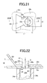
FIG. 21 is a view showing a brake pedal device of yet another embodiment of the present invention, a view showing the shape of the insertion hole of the sub-bracket included in the brake pedal device.
FIG. 22 is a cross sectional view taken along line XXII-XXII of FIG. 21.
FIG. 23 is a view showing a brake pedal device of yet another embodiment of the present invention, a view showing the shape of the insertion hole of the sub-bracket included in the brake pedal device.
FIG. 24 is a cross sectional view taken along line XXIV-XXIV of FIG. 23.
FIG. 25 is a view showing a brake pedal device of yet another embodiment of the present invention, a view showing the shape of the insertion hole of the sub-bracket included in the brake pedal device.
FIG. 26 is a cross sectional view taken along line XXVI-XXVI of FIG. 25.
MODES FOR CARRYING OUT THE INVENTION
An embodiment of the present invention will be described in detail below with reference to the accompanying drawings. In order to facilitate understanding, the figures in the following embodiments are shown simplified or deformed as appropriate, and each part is not necessarily drawn at an accurate dimensional ratio, in an accurate shape, etc.
First Embodiment
FIGS. 1 and 2 are a perspective view and a front view showing a brake pedal device (vehicle pedal device) 10 for a service brake to which the present invention is applied. As shown in FIGS. 1 and 2, the brake pedal device 10 includes: a main bracket 12 that is attached to a dash panel 11 separating an engine compartment from a passenger compartment and that has a pair of plate-shaped side plates 12 a, 12 b facing each other; a first clinching pin 14 having a stepped columnar shape and having its both ends clinched so that the first clinching pin 14 is fixed between the pair of side plates 12 a, 12 b; a brake pedal (pedal) 16 having the shape of a longitudinal flat plate and pivotally supported by the first clinching pin 14; and a stepping portion 16 a that is formed integrally with the brake pedal 16 at the end on the opposite side of the brake pedal 16 from the first clinching pin 14 side and that is depressed when a driver performs a braking operation. An operating rod, not shown, which protrudes from a brake booster into the passenger compartment is coupled via a clevis to an attachment hole 16 b formed at an intermediate position in the brake pedal 16.
Accordingly, as shown in FIG. 2, when the driver depresses the stepping portion 16 a of the brake pedal 16 by the braking operation and the brake pedal 16 pivots in the direction shown by an arrow A about the first clinching pin 14, the operating rod is mechanically pressed according to the pivoting of the brake pedal 16. A brake oil pressure according to the depressing operation force applied to the brake pedal 16 is thus generated from a master cylinder, not shown.
The brake pedal device 10 includes a backward movement preventing mechanism 18 that prevents the stepping portion 16 a of the brake pedal 16 from moving backward toward a driver's seat even if the dash panel 11 moves backward toward the driver's seat by, e.g., a load applied from the front of a vehicle due to a collision etc.
As shown in FIG. 2, the backward movement preventing mechanism 18 includes: a sub-bracket 20 that has a pair of side plate portions 20 a, 20 b having the shape of a longitudinal flat plate and facing each other and a coupling plate portion 20 e coupling rear ends 20 d of the side plate portions 20 a, 20 b so that the sub-bracket 20 has a U-shaped section or an angled U-shaped section, and that couples an end on the opposite side of the main bracket 12 from the dash panel 11 side, namely rear ends 12 c, and an instrument panel reinforcement 19; a second clinching pin (clinching pin) 22 with which ends on the dash panel 11 side of the pair of side plate portions 20 a, 20 b, namely front ends 20 c, are attached to the rear ends 12 c of the pair of side plates 12 a, 12 b of the main bracket 12 by clinching such that the front ends 20 c overlap the rear ends 12 c; a pivot lever 24 having the shape of a longitudinal flat plate and pivotally supported by the second clinching pin 22; and a pair of coupling links 26 that are provided on both sides (the front and back sides of FIG. 2) of the brake pedal 16 and the pivot lever 24 so as to extend between a base portion 24 a of the pivot lever 24 on the second clinching pin 22 side and an end 16 c of the brake pedal 16 on the first clinching pin 14 side and to sandwich the end 16 c and the base portion 24 a therebetween. A cylindrical portion 24 b having a cylindrical shape is fixedly fitted to the base portion 24 a of the pivot lever 24, and a bearing 28 (see FIGS. 5 and 6) such as, e.g., a metal bearing is interposed between the inner peripheral surface of the cylindrical portion 24 b and the outer peripheral surface of the second clinching pin 22 in order to reduce sliding resistance between the cylindrical portion 24 b and the second clinching pin 22. In FIG. 2, one of the side plates of the main bracket 12 which is located closer to the viewer, namely the side plate 12 a, is shown partially cutaway to reveal the coupling structure between the brake pedal 16 and the pivot lever 24 with the pair of coupling links 26.
As shown in FIG. 3, the coupling plate portion 20 e of the sub-bracket 20 is attached to the instrument panel reinforcement 19, and an insertion hole 20 f is formed in each of the front ends 20 c of the pair of side plate portions 20 a, 20 b. A coupling hole 12 d (see FIGS. 5 to 7) is formed in each of the rear ends 12 c of the pair of side plates 12 a, 12 b of the main bracket 12.
As shown in FIGS. 3 and 4, each of the insertion holes 20 f of the sub-bracket 20 is an elongated hole extending substantially in the same direction as the longitudinal direction of the side plate portions 20 a, 20 b, namely in the direction toward the dash panel 11. The end on the rear end 20 d side of the insertion hole 20 f having the shape of an elongated hole has an octagonal shape (polygonal shape), and the inscribed circle C1 of the octagon has a diameter larger than the lateral dimension D1 of the insertion hole 20 f other than the end on the rear end 20 d side. As shown in FIG. 7, each of the coupling holes 12 d of the main bracket 12 has an octagonal shape (polygonal shape). The polygonal shapes of the coupling hole 12 d and the end of the insertion hole 20 f are experimentally determined in advance so that the main bracket 12 and the sub-bracket 20 can turn relative to each other about the second clinching pin 22 when subjected to an impact load. The end on the rear end 20 d side of the insertion hole 20 f having the shape of an elongated hole has substantially the same diameter as the coupling hole 12 d. As shown in FIGS. 4 and 7, the inner peripheral edges of the octagonal coupling hole 12 d and the octagonal insertion hole 20 f have such a non-circular shape that the distances r1, r2 from the centers E1, E2 of the octagonal coupling hole 12 d and the octagonal insertion hole 20 f vary periodically in one circumferential direction about the centers E1, E2. As shown in FIG. 7, the center E1 of the octagonal coupling hole 12 d matches the center E2 of the octagonal insertion hole 20 f in the present embodiment. As shown in FIG. 7, the coupling hole 12 d and the insertion hole 20 f are formed in the side plates 12 a, 12 b and the side plate portions 20 a, 20 b so that the vertices of the octagonal shape of the coupling hole 12 d do not match the vertices of the octagonal shape of the insertion hole 20 f in the state where the front ends 20 c of the pair of side plate portions 20 a, 20 b of the sub-bracket 20 overlap the rear ends 12 c of the pair of side plates 12 a, 12 b of the main bracket 12.
As shown in FIG. 5, the front ends 20 c of the pair of side plate portions 20 a, 20 b of the sub-bracket 20 are extended outward from an intermediate position in the longitudinal direction of the insertion hole 20 f so as to be separated further away from the pair of side plates 12 a, 12 b toward the dash panel 11, i.e., toward the tip ends of the front ends 20 c. In the state where the front ends 20 c of the sub-bracket 20 overlap the rear ends 12 c of the main bracket 12, the height H from the end on the front end 20 c side of each insertion hole 20 f having the shape of an elongated hole to the side plate 12 a, 12 b in the axial direction of the second clinching pin 22 is greater than the height h from each of the ends of the second clinching pin 22 inserted through the coupling holes 12 d to the side plate 12 a, 12 b in the axial direction of the second clinching pin 22. The second clinching pin 22 has a columnar shaft portion 22 a and a pair of columnar clinching portions (both ends) 22 b protruding from both ends of the shaft portion 22 a in the axial direction of the shaft portion 22 a, and has a stepped columnar shape with the diameter of the shaft portion 22 a being larger than that of the clinching portions 22 b. The shaft portion 22 a has such a diameter that the shaft portion 22 a cannot pass through the coupling holes 12 d and the insertion holes 20 f. The clinching portions 22 b have such a diameter that the clinching portions 22 b can pass through the coupling holes 12 d and the insertion holes 20 f.
Accordingly, as shown in FIG. 5, the clinching portions 22 b of the second clinching pin 22 can be inserted through the insertion holes 20 f of the sub-bracket 20 by moving the front ends 20 c of the sub-bracket 20 toward the clinching portions 22 b of the second clinching pin 22 inserted through the coupling holes 12 d of the main bracket 12. That is, the insertion holes 20 f have the shape of an elongated hole having such a length that allows the clinching portions 22 h of the second clinching pin 22 which protrude from the coupling holes 12 d of the pair of side plates 12 a, 12 b to pass therethrough in the state where the front ends 20 c of the side plate portions 20 a, 20 b are extended outward. The longitudinal length of the insertion holes 20 f having the shape of an elongated hole, the height of the clinching portions 22 b (clinching margin) of the second clinching pin 22, the opening angle θ of the front ends 20 c of the side plate portions 20 a, 20 b which are extended outward with respect to the side plates 12 a, 12 b, etc. may be adjusted as appropriate so that the sub-bracket 20 does not interfere with the second clinching pin 22 when the clinching portions 22 b of the second clinching pin 22 are inserted through the insertion holes 20 f of the sub-bracket 20. For example, the longitudinal length of the insertion holes 20 f having the shape of an elongated hole may be reduced if the opening angle θ is large. The longitudinal length of the insertion holes 20 f having the shape of an elongated hole need be increased if the opening angle θ is small.
As shown in FIGS. 1 and 2, the rear ends 20 d of the sub-bracket 20, namely the coupling plate portion 20 e, are located higher from, e.g., a floor, not shown, than the insertion holes 20 f formed in the front ends 20 c of the sub-bracket 20. When the brake pedal 16 is not operated, a tip end 24 c on the opposite side of the pivot lever 24 from the second clinching pin 22 side is in contact with the coupling plate portion 20 e of the sub-bracket 20 or is located close to the coupling plate portion 20 e.
In the backward movement preventing mechanism 18 of the brake pedal device 10 configured as described above, if the dash panel 11 moves backward toward the driver's seat by, e.g., a load applied from the front of the vehicle due to a collision etc., a force F is applied from the instrument panel reinforcement 19 to the rear ends 20 d of the sub-bracket 20, namely the coupling plate portion 20 e, and the sub-bracket 20 is caused to pivot with respect to the main bracket 12 in the direction shown by an arrow B about the second clinching pin 22. Moreover, the tip end 24 c of the pivot lever 24 contacts the coupling plate portion 20 e, and the pivot lever 24 is caused to pivot in the direction shown by the arrow B about the second clinching pin 22. The brake pedal 16 is thus caused to pivot in the direction in which the brake pedal 16 is operated, namely the direction shown by the arrow A, via the pair of coupling links 26. The stepping portion 16 a of the brake pedal 16 is therefore prevented from moving backward toward the driver's seat even if the dash panel 11 moves backward.
A method for attaching the sub-bracket 20 to the main bracket 12 will be described below with reference to FIGS. 5 to 7. First, as shown in FIG. 5, the second clinching pin 22 is fitted through the cylindrical portion 24 b of the pivot lever 24, and the clinching portions 22 b that are both ends of the second clinching pin 22 are inserted through the coupling holes 12 d formed in the side plates 12 a, 12 b of the main bracket 12. Next, the front ends 20 c of the sub-bracket 20 are moved toward the clinching portions 22 b of the second clinching pin 22 inserted through the coupling holes 12 d of the main bracket 12, so that the clinching portions 22 b of the second clinching pin 22 are inserted through the insertion holes 20 f of the sub-bracket 20. Preferably, as shown in FIG. 7, positioning is performed with, e.g., a positioning jig etc. so that the center E2 of the end of the insertion hole 20 f on the rear end 20 d side, the center E1 of the coupling hole 12 d, and the axis G of the clinching portion 22 b of the second clinching pin 22 match each other in position.
Then, as shown in FIG. 5, in the state where the clinching portions 22 b of the second clinching pin 22 inserted through the coupling holes 12 d are inserted through the insertion holes 20 f and positioned as described above, the clinching portions 22 b of the second clinching pin 22 are compressed in the axial direction of the second clinching pin 22 by clinching with, e.g., a clinching machine etc. As shown in FIG. 6, the rear ends 12 e of the pair of side plates 12 a, 12 b of the main bracket 12 are thus attached to the front ends 20 c of the pair of side plate portions 20 a, 20 b of the sub-bracket 20 by clinching such that the rear ends 12 c closely contact the front ends 20 c, whereby the sub-bracket 20 is attached to the main bracket 12. When both ends of the second clinching pin 22 are compressed in the axial direction of the second clinching pin 22 by press clinching, the clinching portions 22 b of the second clinching pin 22 expand toward the inner peripheral surfaces of the octagonal coupling holes 12 d and the octagonal insertion holes 20 f, as shown in FIG. 7. Those parts of the front ends 20 c of the sub-bracket 20 which are extended outward so as to be separated away from the side plates 12 a, 12 b of the main bracket 12 may be bent so as to extend substantially parallel to the side plates 12 a, 12 b of the main bracket 12 after the clinching portions 22 b of the second clinching pin 22 are inserted through the insertion holes 20 f of the sub-bracket 20 or after the clinching portions 22 b of the second clinching pin 22 are clinched.
As described above, according to the brake pedal device 10 of the present embodiment, the inner peripheral edges of the coupling holes 12 d and the insertion holes 20 f have a non-circular shape such as, e.g., an octagonal shape in which the distances r1, r2 from the centers E1, E2 of the coupling hole 12 d and the insertion hole 20 f vary periodically in one circumferential direction about the centers E1, E2. Accordingly, when both ends of the second clinching pin 22 are compressed in the axial direction of the second clinching pin 22 by clinching in the state where the clinching portions 22 b of the second clinching pin 22 inserted through the coupling holes 12 d are inserted through the insertion holes 20 f, the clinching portions 22 b of the second clinching pin 22 expand toward the inner peripheral surfaces of the octagonal coupling holes 12 d and the octagonal insertion holes 20 f. The inner peripheral surfaces of the coupling holes 12 d and the insertion holes 20 f therefore serve as stoppers that stop turning of the sub-bracket 20 with respect to the main bracket 12 about the second clinching pin 22. The sub-bracket 20 can thus be prevented from easily turning with respect to the main bracket 12 by a relatively light load. Since the pair of side plates 12 a, 12 b of the main bracket 12 are attached to the pair of side plate portions 20 a, 20 b of the sub-bracket 20 by clinching of the second clinching pin 22, an increase in the number of parts and an increase in assembly time can be suppressed as compared to conventional vehicle pedal devices in which a pair of side plates of a main bracket are fastened to a pair of side plate portions of a sub-bracket with a bolt and nuts.
According to the brake pedal device 10 of the present embodiment, the front ends 20 c of the pair of side plate portions 20 a, 20 b of the sub-bracket 20 are extended outward so as to be separated further away from the pair of side plates 12 a, 12 b of the main bracket 12 toward the dash panel 11, i.e., toward the tip ends of the front ends 20 c. The insertion holes 20 f formed in the pair of side plate portions 20 a, 20 b have the shape of an elongated hole having such a length that allows the clinching portions 22 b that are both ends of the second clinching pin 22 and protrude from the pair of side plates 12 a, 12 b to pass therethrough in the state where the front ends 20 c of the side plate portions 20 a, 20 b are extended outward. Accordingly, the clinching portions 22 b of the second clinching pin 22 can be inserted through the insertion holes 20 f of the sub-bracket 20 by moving the front ends 20 c of the sub-bracket 20 toward the clinching portions 22 b of the second clinching pin 22 inserted through the coupling holes 12 d of the main bracket 12. This can improve workability in attaching the sub-bracket 20 to the main bracket 12.
According to the brake pedal device 10 of the present embodiment, the second clinching pin 22 turnably supports the pivot lever 24 that, when the dash panel 11 moves backward and the sub-bracket 20 is caused to pivot with respect to the main bracket 12 in the direction shown by the arrow B about the second clinching pin 22, pivots together with the sub-bracket 20 to cause the brake pedal 16 to pivot in the direction in which the brake pedal 16 is operated. Accordingly, if the dash panel 11 moves backward, the main bracket 12 and the sub-bracket 20 which have been attached to each other by clinching are folded about the second clinching pin 22. The brake pedal device 10 can thus have the backward movement preventing capability to prevent the stepping portion 16 a of the brake pedal 16 from moving backward toward the driver's seat.
According to the brake pedal device 10 of the present embodiment, the rear ends 20 d of the sub-bracket 20 are located higher from the floor than the insertion holes 20 f formed in the front ends 20 c of the sub-bracket 20. This allows the sub-bracket 20 to pivot with respect to the main bracket 12 about the second clinching pin 22 in a preferable manner if the dash panel 11 moves backward. Moreover, a load that causes the sub-bracket 20 to pivot with respect to the main bracket 12 about the second clinching pin 22 can be set by adjusting the number of vertices of the shape of the coupling holes 12 d and the insertion holes 20 f as appropriate, namely by setting the number of vertices to 8 in the present embodiment.
Other embodiments of the present invention will be described in detail below with reference to the drawings. In the following description, the same portions in different embodiments are denoted with the same reference numerals, and description thereof will be omitted.
Second Embodiment
As shown in FIGS. 8 and 9, in a brake pedal device (vehicle pedal device) of the present embodiment, coupling holes 12 e and insertion holes 20 g are different in shape from the coupling holes 12 d and the insertion holes 20 f in the brake pedal device 10 of the first embodiment. The brake pedal device of the present embodiment is otherwise substantially similar to the brake pedal device 10 of the first embodiment.
As shown in FIG. 8, each of the insertion holes 20 g of the sub-bracket 20 is an elongated hole extending substantially in the same direction as the longitudinal direction of the side plate portions 20 a, 20 b, namely in the direction toward the dash panel 11, in a manner substantially similar to that of the insertion holes 20 f of the first embodiment. The end on the rear end 20 d side of the insertion hole 20 g having the shape of an elongated hole has a hexagonal shape (polygonal shape), and the inscribed circle C2 of the hexagon has a diameter larger than the lateral dimension D1 of the insertion hole 20 g other than the end on the rear end 20 d side. As shown in FIG. 9, each of the coupling holes 12 e of the main bracket 12 has a hexagonal shape (polygonal shape). The coupling holes 12 e and the insertion holes 20 g are sized so as not to allow the shaft portion 22 a of the second clinching pin 22 to pass therethrough and so as to allow the clinching portions 22 b of the second clinching pin 22 to pass therethrough. When both ends of the second clinching pin 22 are compressed in the axial direction by clinching, the clinching portions 22 b of the second clinching pin 22 expand toward the inner peripheral surfaces of the hexagonal coupling holes 12 e and the hexagonal insertion holes 20 g. As in the first embodiment, the inner peripheral surfaces of the coupling holes 12 e and the insertion holes 20 g therefore serve as stoppers that stop turning of the sub-bracket 20 with respect to the main bracket 12 about the second clinching pin 22. As shown in FIGS. 8 and 9, the inner peripheral edges of the hexagonal coupling hole 12 e and the hexagonal insertion hole 20 g have such a non-circular shape that the distances r3, r4 from the centers E3, E4 of the coupling hole 12 e and the insertion hole 20 g vary periodically in one circumferential direction about the centers E3, E4.
Third Embodiment
As shown in FIGS. 10 and 11, in a brake pedal device (vehicle pedal device) of the present embodiment, coupling holes 12 f and insertion holes 20 h are different in shape from the coupling holes 12 d and the insertion holes 20 f in the brake pedal device 10 of the first embodiment. The brake pedal device of the present embodiment is otherwise substantially similar to the brake pedal device 10 of the first embodiment.
As shown in FIG. 10, each of the insertion holes 20 h of the sub-bracket 20 is an elongated hole extending substantially in the same direction as the longitudinal direction of the side plate portions 20 a, 20 b, namely in the direction toward the dash panel 11, in a manner substantially similar to that of the insertion holes 20 f of the first embodiment. The end on the rear end 20 d side of the insertion hole 20 h having the shape of an elongated hole has a quadrilateral shape (polygonal shape), and the inscribed circle C3 of the quadrilateral shape has a diameter larger than the lateral dimension D1 of the insertion hole 20 h other than the end on the rear end 20 d side. As shown in FIG. 11, each of the coupling holes 12 f of the main bracket 12 has a quadrilateral shape (polygonal shape). The coupling holes 12 f and the insertion holes 20 h are sized so as not to allow the shaft portion 22 a of the second clinching pin 22 to pass therethrough and so as to allow the clinching portions 22 b of the second clinching pin 22 to pass therethrough. When both ends of the second clinching pin 22 are compressed in the axial direction by clinching, the clinching portions 22 b of the second clinching pin 22 expand toward the inner peripheral surfaces of the quadrilateral coupling holes 12 f and the quadrilateral insertion holes 20 h. As in the first embodiment, the inner peripheral surfaces of the coupling holes 12 f and the insertion holes 20 h therefore serve as stoppers that stop turning of the sub-bracket 20 with respect to the main bracket 12 about the second clinching pin 22. As shown in FIGS. 10 and 11, the inner peripheral edges of the quadrilateral coupling hole 12 f and the quadrilateral insertion hole 20 h have such a non-circular shape that the distances r5, r6 from the centers E5, E6 of the coupling hole 12 f and the insertion hole 20 h vary periodically in one circumferential direction about the centers E5, E6.
Fourth Embodiment
As shown in FIGS. 12 and 13, in a brake pedal device (vehicle pedal device) 30 of the present embodiment, front ends 20 i of the side plate portions 20 a, 20 b of the sub-bracket 20 are different in shape from the front ends 20 c of the side plate portions 20 a, 20 b in the brake pedal device 10 of the first embodiment. The brake pedal device 30 of the present embodiment is otherwise substantially similar to the brake pedal device 10 of the first embodiment.
As shown in FIGS. 12 and 13, each of the front ends 20 i of the pair of side plate portions 20 a, 20 b of the sub-bracket 20 integrally includes an outwardly extended portion 20 j extended outward from an intermediate position in the longitudinal direction of the insertion hole 20 f so as to be separated further away from the side plate 12 a, 12 b toward the dash panel 11, i.e., toward the tip end of the front end 20 i, and a bent portion 20 k formed by bending the tip end part of the outwardly extended portion 20 j so as to extend substantially parallel to the side plate 12 a, 12 b. That is, the front ends 20 i of the sub-bracket 20 are bent twice. As shown in FIG. 13, in the state where the front ends 20 i of the sub-bracket 20 overlap the rear ends 12 c of the main bracket 12, the height H1 from the end on the front end 20 i side of each insertion hole 20 f having the shape of an elongated hole to the side plate 12 a, 12 b in the axial direction of the second clinching pin 22 is greater than the height h from each of the ends of the second clinching pin 22 before clinching, which have been inserted through the coupling holes 12 d, to the side plate 12 a, 12 b in the axial direction of the second clinching pin 22, as in the first embodiment.
According to the brake pedal device 30 of the present embodiment, each of the front ends 20 i of the pair of side plate portions 20 a, 20 b of the sub-bracket 20 includes the outwardly extended portion 20 j extended outward so as to be separated away from the side plate 12 a, 12 b, and the bent portion 20 k formed by bending the tip end part of the outwardly extended portion 20 j so as to extend substantially parallel to the side plate 12 a, 12 b, and the front ends 20 i are thus bent twice. This can minimize the lateral dimension D2 of the sub-bracket 20 in the axial direction of the second clinching pin 22 while securing the height H1 of the insertion holes 20 f of the sub-bracket 20 in the axial direction of the second clinching pin 22.
Fifth Embodiment
As shown in FIG. 14, in a brake pedal device (vehicle pedal device) of the present embodiment, front ends 20 l of the side plate portions 20 a, 20 b of the sub-bracket 20 are different in shape from the front ends 20 c of the side plate portions 20 a, 20 b in the brake pedal device 10 of the first embodiment. The brake pedal device of the present embodiment is otherwise substantially similar to the brake pedal device 10 of the first embodiment.
As shown in FIG. 14, the front ends 20 l of the sub-bracket 20, namely the side plate portions 20 a, 20 b, are substantially parallel to the side plates 12 a, 12 b, and are not extended outward like the front ends 20 c of the first embodiment. Each of the front ends 20 l of the sub-bracket 20 has a cutout 20 m formed in its tip end part. Each cutout 20 m extends in the longitudinal direction of the side plate portion 20 a, 20 b, namely in the direction toward the dash panel 11, as in the first embodiment. Like the end on the rear end 20 d side of the insertion hole 20 f having the shape of an elongated hole in the first embodiment, the end of the cutout 20 m on the rear end 20 d side has an octagonal shape, and the inscribed circle of the octagon has a diameter larger than the lateral dimension of the cutout 20 m other than the end on the rear end 20 d side. Each cutout 20 m is sized so as not to allow the shaft portion 22 a of the second clinching pin 22 to pass therethrough and so as to allow the clinching portion 22 b of the second clinching pin 22 to pass therethrough.
Accordingly, the clinching portions 22 b of the second clinching pin 22 can be inserted through the cutouts 20 m of the sub-bracket 20 by moving the front ends 20 l of the sub-bracket 20 toward the clinching portions 22 b of the second clinching pin 22 inserted through the coupling holes 12 d of the main bracket 12.
According to the brake pedal device of the present embodiment, each of the front ends 20 l of the pair of side plate portions 20 a, 20 b of the sub-bracket 20 has the cutout 20 m formed in its tip end part. Since the cutouts 20 m are formed in the front ends 20 l, the front ends 20 l of the sub-bracket 20 need not be extended outward so as to be separated away from the side plates 12 a, 12 b as in, e.g., the first to fourth embodiments. This can minimize an increase in lateral size of the sub-bracket 20 and an increase in weight of the sub-bracket 20.
Sixth Embodiment
As shown in FIGS. 15 and 16, in a brake pedal device (vehicle pedal device) of the present embodiment, coupling holes 12 g and insertion holes 20 n are different in shape from the coupling holes 12 d and the insertion holes 20 f in the brake pedal device 10 of the first embodiment. The brake pedal device of the present embodiment is otherwise substantially similar to the brake pedal device 10 of the first embodiment.
As shown in FIG. 15, each of the insertion holes 20 n of the sub-bracket 20 is an elongated hole extending substantially in the same direction as the longitudinal direction of the side plate portions 20 a, 20 b, namely in the direction toward the dash panel 11, in a manner substantially similar to that of the insertion holes 20 f of the first embodiment. The end on the rear end 20 d side of the insertion holes 20 n having the shape of an elongated hole has an elliptical shape. As shown in FIG. 16, each of the coupling holes 12 g of the main bracket 12 has an elliptical shape. The coupling holes 12 g and the insertion holes 20 n are sized so as not to allow the shaft portion 22 a of the second clinching pin 22 to pass therethrough and so as to allow the clinching portions 22 b of the second clinching pin 22 to pass therethrough. When both ends of the second clinching pin 22 are compressed in the axial direction by clinching, the clinching portions 22 b of the second clinching pin 22 expand toward the inner peripheral surfaces of the elliptical coupling holes 12 g and the elliptical insertion holes 20 n in the longitudinal direction. As in the first embodiment, the inner peripheral surfaces of the coupling holes 12 g and the insertion holes 20 n therefore serve as stoppers that stop turning of the sub-bracket 20 with respect to the main bracket 12 about the second clinching pin 22.
As shown in FIGS. 15 and 16, the inner peripheral edges of the elliptical coupling hole 12 g and the elliptical insertion hole 20 n have such a non-circular shape that the distances r7, r8 from the centers E7, E8 of the coupling hole 12 g and the insertion hole 20 n vary periodically in one circumferential direction about the centers E7, E8.
Seventh Embodiment
As shown in FIGS. 17 and 18, in a brake pedal device (vehicle pedal device) of the present embodiment, coupling holes 12 h and insertion holes 20 o are different in shape from the coupling holes 12 d and the insertion holes 20 f in the brake pedal device 10 of the first embodiment. The brake pedal device of the present embodiment is otherwise substantially similar to the brake pedal device 10 of the first embodiment.
As shown in FIG. 17, each of the insertion holes 20 o of the sub-bracket 20 is an elongated hole extending substantially in the same direction as the longitudinal direction of the side plate portions 20 a, 20 b, namely in the direction toward the dash panel 11, in a manner substantially similar to that of the insertion holes 20 f of the first embodiment. The end on the rear end 20 d side of the insertion hole 20 o having the shape of an elongated hole has a triangular shape with rounded corners As shown in FIG. 18, each of the coupling holes 12 h of the main bracket 12 has a triangular shape with rounded corner. The coupling holes 12 h and the insertion holes 20 o are sized so as not to allow the shaft portion 22 a of the second clinching pin 22 to pass therethrough and so as to allow the clinching portions 22 b of the second clinching pin 22 to pass therethrough. When both ends of the second clinching pin 22 are compressed in the axial direction by clinching, the clinching portions 22 b of the second clinching pin 22 expand toward the inner peripheral surfaces with rounded corners of the triangular coupling holes 12 h and the triangular insertion holes 20 o. As in the first embodiment, the inner peripheral surfaces of the coupling holes 12 h and the insertion holes 20 o therefore serve as stoppers that stop turning of the sub-bracket 20 with respect to the main bracket 12 about the second clinching pin 22. As shown in FIGS. 17 and 18, the inner peripheral edges of the triangular coupling hole 12 h and the triangular insertion hole 20 o have such a non-circular shape that the distances r9, r10 from the centers E9, E10 of the coupling hole 12 h and the insertion hole 20 o vary periodically in one circumferential direction about the centers E9, E10.
Eighth Embodiment
As shown in FIGS. 19 and 20, in a brake pedal device (vehicle pedal device) of the present embodiment, coupling holes 12 i and insertion holes 20 p are different in shape from the coupling holes 12 d and the insertion holes 20 f in the brake pedal device 10 of the first embodiment. The brake pedal device of the present embodiment is otherwise substantially similar to the brake pedal device 10 of the first embodiment.
As shown in FIG. 19, each of the insertion holes 20 p of the sub-bracket 20 is an elongated hole extending substantially in the same direction as the longitudinal direction of the side plate portions 20 a, 20 b, namely in the direction toward the dash panel 11, in a manner substantially similar to that of the insertion holes 20 f of the first embodiment. The end on the rear end 20 d side of the insertion hole 20 p having the shape of an elongated hole has an elongated hole shape extending in the direction perpendicular to the longitudinal direction of the insertion hole 20 p. As shown in FIG. 20, each of the coupling holes 12 i of the main bracket 12 has an elongated hole shape extending substantially in the same direction as the longitudinal direction of the insertion holes 20 p. The coupling holes 12 i and the insertion holes 20 p are sized so as not to allow the shaft portion 22 a of the second clinching pin 22 to pass therethrough and so as to allow the clinching portions 22 b of the second clinching pin 22 to pass therethrough. When both ends of the second clinching pin 22 are compressed in the axial direction by clinching, the clinching portions 22 h of the second clinching pin 22 expand toward the inner peripheral surfaces of the ends of the coupling holes 12 i having an elongated hole shape and the insertion holes 20 p having an elongated hole shape. As in the first embodiment, the inner peripheral surfaces of the coupling holes 12 i and the insertion holes 20 p therefore serve as stoppers that stop turning of the sub-bracket 20 with respect to the main bracket 12 about the second clinching pin 22. As shown in FIGS. 19 and 20, the inner peripheral edges of the coupling hole 12 i having an elongated hole shape and the insertion hole 20 p having an elongated hole shape have such a non-circular shape that the distances r11, r12 from the centers E11, E12 of the coupling hole 12 i and the insertion hole 20 p vary periodically in one circumferential direction about the centers E11, E12.
Ninth Embodiment
As shown in FIGS. 21 and 22, in a brake pedal device (vehicle pedal device) of the present embodiment, insertion holes 20 q are different in shape from the insertion holes 20 f in the brake pedal device 10 of the first embodiment. The brake pedal device of the present embodiment is otherwise substantially similar to the brake pedal device 10 of the first embodiment. That is, the end of each insertion hole 20 q on the rear end 20 d side has the same octagonal shape as the end of the insertion hole 20 f on the rear end 20 d side, and the insertion hole 20 q other than the end on the rear end 20 d side has a different shape from the elongated hole shape of the insertion hole 20 f other than the end on the rear end 20 d side. Since the insertion hole 20 q is formed similarly in both of the front ends 20 c of the pair of side plate portions 20 a, 20 b, only the front end 20 c of the side plate portion 20 a will be described below.
As shown in FIG. 21, the insertion hole 20 q other than the end on the rear end 20 d side has a polygonal shape such as, e.g., a trapezoidal shape. As shown in FIGS. 21 and 22, each of the front ends 20 c of the side plate portion 20 a of the sub-bracket 20 extends outward from an intermediate position of the insertion hole 20 q having a trapezoidal shape so as to be separated further away from the side plate 12 a toward the dash panel 11, i.e., toward the tip end of the front end 20 c. As shown in FIG. 22, in the state where the front ends 20 e of the sub-bracket 20 overlap the rear ends 12 c of the main bracket 12, the height H from the end 20 r on the front end 20 c side of each insertion hole 20 q to the side plate 12 a in the axial direction of the second clinching pin 22 is greater than the height h from each of the ends of the second clinching pin 22 inserted through the coupling holes 12 d to the side plate 12 a in the axial direction of the second clinching pin 22. Accordingly, as in the first embodiment, the clinching portions 22 b of the second clinching pin 22 can be inserted through the insertion holes 20 q of the sub-bracket 20 by moving the front ends 20 c of the sub-bracket 20 toward the clinching portions 22 b of the second clinching pin 22 inserted through the coupling holes 12 d of the main bracket 12. Each insertion hole 20 q has the shape of such an elongated hole that the longitudinal dimension L1 of the insertion hole 20 q in the longitudinal direction of the side plate portions 20 a, 20 b is larger than the lateral dimension L2 of the octagonal end on the rear end 20 d side of the insertion hole 20 q in the direction perpendicular to the longitudinal direction of the side plate portions 20 a, 20 b. That is, the insertion holes 20 q are elongated holes extending generally in the longitudinal direction of the side plate portions 20 a, 20 b like the insertion holes 20 f of the first embodiment.
Tenth Embodiment
As shown in FIGS. 23 and 24, in a brake pedal device (vehicle pedal device) of the present embodiment, insertion holes 20 s are different in shape from the insertion holes 20 f in the brake pedal device 10 of the first embodiment. The brake pedal device of the present embodiment is otherwise substantially similar to the brake pedal device 10 of the first embodiment. That is, the end of each insertion hole 20 s on the rear end 20 d side has the same octagonal shape as the end of the insertion hole 20 f on the rear end 20 d side, and the insertion hole 20 s other than the end on the rear end 20 d side has a different shape from the elongated hole shape of the insertion hole 20 f other than the end on the rear end 20 d side. Since the insertion holes 20 s are formed similarly in both of the front ends 20 c of the pair of side plate portions 20 a, 20 b, only the front end 20 c of the side plate portion 20 a will be described below.
As shown in FIG. 23, the insertion hole 20 s other than the end on the rear end 20 d side has a circular shape. As shown in FIGS. 23 and 24, each of the front ends 20 c of the side plate portion 20 a of the sub-bracket 20 extends outward from an intermediate position of the insertion hole 20 s having a circular shape so as to be separated further away from the side plate 12 a toward the dash panel 11, i.e., toward the tip end of the front end 20 c. As shown in FIG. 24, in the state where the front ends 20 c of the sub-bracket 20 overlap the rear ends 12 c of the main bracket 12, the height H from the end 20 t on the front end 20 c side of each insertion hole 20 s to the side plate 12 a in the axial direction of the second clinching pin 22 is greater than the height h from each of the ends of the second clinching pin 22 inserted through the coupling holes 12 d to the side plate 12 a in the axial direction of the second clinching pin 22. Accordingly, as in the first embodiment, the clinching portions 22 b of the second clinching pin 22 can be inserted through the insertion holes 20 s of the sub-bracket 20 by moving the front ends 20 c of the sub-bracket 20 toward the clinching portions 22 b of the second clinching pin 22 inserted through the coupling holes 12 d of the main bracket 12. Each insertion hole 20 s has the shape of such an elongated hole that the longitudinal dimension L3 of the insertion hole 20 s in the longitudinal direction of the side plate portions 20 a, 20 b is larger than the lateral dimension L4 of the octagonal end on the rear end 20 d side of the insertion hole 20 s in the direction perpendicular to the longitudinal direction of the side plate portions 20 a, 20 b. That is, the insertion holes 20 s are elongated holes extending generally in the longitudinal direction of the side plate portions 20 a, 20 b like the insertion holes 20 f of the first embodiment.
Eleventh Embodiment
As shown in FIGS. 25 and 26, in a brake pedal device (vehicle pedal device) of the present embodiment, insertion holes 20 u are different in shape from the insertion holes 20 f in the brake pedal device 10 of the first embodiment. The brake pedal device of the present embodiment is otherwise substantially similar to the brake pedal device 10 of the first embodiment. Since the insertion holes 20 u are formed similarly in both of the front ends 20 c of the pair of side plate portions 20 a, 20 b, only the front end 20 c of the side plate portion 20 a will be described below.
As shown in FIG. 25, each of the insertion holes 20 u has a polygonal shape, for example, an octagonal shape. The inner peripheral edge of the octagonal insertion hole 20 u has such a non-circular shape that the distance r13 from the center E13 of the insertion hole 20 u varies periodically in one circumferential direction about the center E13.
As shown in FIGS. 25 and 26, each of the front ends 20 c of the side plate portion 20 a of the sub-bracket 20 extends outward from an intermediate position of the octagonal insertion hole 20 u so as to be separated further away from the side plate 12 a toward the dash panel 11, i.e., toward the tip end of the front end 20 c. As shown in FIG. 26, in the state where the front ends 20 c of the sub-bracket 20 overlap the rear ends 12 c of the main bracket 12, the height H from the end 20 v on the front end 20 e side of each insertion hole 20 u to the side plate 12 a in the axial direction of the second clinching pin 22 is greater than the height h from each of the ends of the second clinching pin 22 inserted through the coupling holes 12 d to the side plate 12 a in the axial direction of the second clinching pin 22.
Accordingly, as in the first embodiment, the clinching portions 22 b of the second clinching pin 22 can be inserted through the insertion holes 20 u of the sub-bracket 20 by moving the front ends 20 c of the sub-bracket 20 toward the clinching portions 22 b of the second clinching pin 22 inserted through the coupling holes 12 d of the main bracket 12. And after that, when the both ends of the second clinching pin 22 are compressed in the axial direction of the second clinching pin 22 by clinching, parts of the front ends 20 c of the sub-bracket 20 extended outward deforms in substantially parallel to the side plate 12 a, 12 b and, the clinching portions 22 b of the second clinching pin 22 expand toward the inner peripheral surfaces of the octagonal coupling holes 12 d and the octagonal insertion holes 20 u.
Although the embodiments of the present invention are described above based on the drawings, the present invention is applicable in other forms.
For example, although the present invention is applied to the brake pedal devices 10, 30 in the embodiments, the present invention need not necessarily be applied to the brake pedal devices 10, 30. For example, the present invention may be applied to vehicle pedal devices such as an accelerator pedal device, a parking brake pedal device, and a clutch pedal device.
In the first to third embodiments, the ends on the rear end 20 d side of the insertion holes 20 f, 20 g, 20 h having the shape of an elongated hole and the coupling holes 12 d, 12 e, 12 f have a quadrilateral shape, a hexagonal shape, or an octagonal shape. However, the ends of the insertion holes 20 f, 20 g, 20 h on the rear end 20 d side and the coupling holes 12 d, 12 e, 12 f may have other polygonal shapes. In the embodiments, the ends on the rear end 20 d side of the insertion holes 20 f, 20 g, 20 h, 20 n, 20 o, 20 p having the shape of an elongated hole and the coupling holes 12 d, 12 e, 12 f, 12 g, 12 h, 12 i have a quadrilateral shape, a hexagonal shape, an octagonal shape, an elliptical shape, a triangular shape with rounded corners, or an elongated hole shape. However, the ends of the insertion holes 20 f, 20 g, 20 h, 20 n, 20 o, 20 p on the rear end 20 d side and the coupling holes 12 d, 12 e, 12 f, 12 g, 12 h, 12 i may have other shapes. That is, the inner peripheral edges of the ends on the rear end 20 d side of the insertion holes 20 f, 20 g, 20 h, 20 n, 20 o, 20 p having the shape of an elongated hole and the coupling holes 12 d, 12 e, 12 f, 12 g, 12 h, 12 i may have any non-circular shape in which the distances r1 to r12 from the centers E1 to E12 of the ends of the insertion holes 20 f, 20 g, 20 h, 20 n, 20 o, 20 p on the rear end 20 d side and the coupling holes 12 d, 12 e, 12 f, 12 g, 12 h, 12 i vary in one circumferential direction about the centers E1 to E12.
In the embodiments, as shown in FIGS. 7, 9, and 11, the polygonal coupling holes 12 d, 12 e, 12 f and the polygonal insertion holes 20 f, 20 g, 20 h are positioned so that the vertices of the polygonal coupling hole 12 d, 12 e, 12 f do not match the vertices of the polygonal insertion hole 20 f, 20 g, 20 h in the state where the front ends 20 c of the pair of side plate portions 20 a, 20 h of the sub-bracket 20 overlap the rear ends 12 c of the pair of side plates 12 a, 12 b of the main bracket 12. However, the polygonal coupling holes 12 d, 12 e, 12 f and the polygonal insertion holes 20 f, 20 g, 20 h may be positioned so that the vertices of the coupling hole 12 d, 12 e, 12 f match the vertices of the insertion hole 20 f, 20 g, 20 h. That is, the coupling holes 12 d, 12 e, 12 f and the insertion holes 20 f, 20 g, 20 h which are formed in the main bracket 12 and the sub-bracket 20 function as the stoppers regardless of whether or not the vertices of the coupling hole 12 d, 12 e, 12 f match the vertices of the insertion hole 20 f, 20 g, 20 h when the sub-bracket 20 is attached to the main bracket 12. Accordingly, positioning of the holes need not be considered when forming the holes and when attaching the sub-bracket 20 to the main bracket 12. The use of the polygonal holes therefore does not affect workability.
In the first to third embodiments and the sixth to eighth embodiments, the insertion holes 20 f, 20 g, 20 h, 20 n, 20 o, 20 p other than the ends on the rear end 20 d side have the shape of an elongated hole so as to allow the clinching portions 22 b of the second clinching pin 22 to pass therethrough. However, the insertion holes 20 q, 20 s, 20 u other than the ends on the rear end 20 d side may have any shape such as, e.g., a trapezoidal shape or a circular shape like the insertion holes 20 q, 20 s of the ninth and tenth embodiments, as long as the clinching portions 22 b of the second clinching pin 22 can pass therethrough. Like the insertion holes 20 u of the eleventh embodiment, the insertion holes need not necessarily have a portion that allows the clinching portions 22 b of the second clinching pin 22 to pass therethrough as in the ninth and tenth embodiments.
In the embodiments, as shown in FIG. 7, positioning is performed with, e.g., a jig etc. so that the center E2 of the end of the insertion hole 20 f on the rear end 20 d side, the center E1 of the coupling hole 12 d, and the axis G of the clinching portion 22 b of the second clinching pin 22 match each other in position. However, positioning need not necessarily be performed with a jig etc. so that the center E2 of the insertion hole 20 f, the center E1 of the coupling hole 12 d, and the axis G of the clinching portion 22 b match each other in position. For example, if the clinching portions 22 b are clinched with the axis G of the clinching portion 22 b being shifted from the center E2 of the insertion hole 20 f and the center E1 of the coupling hole 12 d, the clinched clinching portions 22 b expand toward the inner peripheral surfaces of the coupling holes 12 d and the insertion holes 20 f. The second clinching pin 22 thus moves so that the axis G of the clinching portion 22 b matches the center E2 of the insertion hole 20 f and the center E1 of the coupling hole 12 d.
In the embodiments, the coupling holes 12 d have substantially the same diameter as the ends of the insertion holes 20 f on the rear end 20 d side. However, for example, the coupling holes 12 d may have a smaller diameter than the ends of the insertion holes 20 f on the rear end 20 d side.
Although not illustrated individually, the present invention can be carried out in various modified or improved forms based on the knowledge of those skilled in the art.
NOMENCLATURE OF ELEMENTS
10, 30: brake pedal device (vehicle pedal device) 11: dash panel 12: main bracket 12 a, 12 b: side plates 12 c: rear ends 12 d: coupling hole 16: brake pedal (pedal) 19: instrument panel reinforcement 20: sub-bracket 20 a, 20 b: side plate portions 20 c: front ends 20 d: rear ends 20 f, 20 g, 20 h, 20 n, 20 o, 20 p, 20 q, 20 s, 20 u: insertion hole (elongated hole) 22: second clinching pin (clinching pin) 22 b: clinching portions (both ends) 24: pivot lever