US954405A - Sealing-cap for bottles. - Google Patents
Sealing-cap for bottles. Download PDFInfo
- Publication number
- US954405A US954405A US46114408A US1908461144A US954405A US 954405 A US954405 A US 954405A US 46114408 A US46114408 A US 46114408A US 1908461144 A US1908461144 A US 1908461144A US 954405 A US954405 A US 954405A
- Authority
- US
- United States
- Prior art keywords
- cap
- bottle
- sealing
- skirt
- flange
- Prior art date
- Legal status (The legal status is an assumption and is not a legal conclusion. Google has not performed a legal analysis and makes no representation as to the accuracy of the status listed.)
- Expired - Lifetime
Links
- 238000007789 sealing Methods 0.000 description 17
- 238000005452 bending Methods 0.000 description 6
- 239000002184 metal Substances 0.000 description 3
- 238000000034 method Methods 0.000 description 2
- 241000464908 Elliptica Species 0.000 description 1
- 241000238631 Hexapoda Species 0.000 description 1
- 238000010276 construction Methods 0.000 description 1
- 230000008602 contraction Effects 0.000 description 1
- 230000009193 crawling Effects 0.000 description 1
- CEJLBZWIKQJOAT-UHFFFAOYSA-N dichloroisocyanuric acid Chemical compound ClN1C(=O)NC(=O)N(Cl)C1=O CEJLBZWIKQJOAT-UHFFFAOYSA-N 0.000 description 1
- 235000013399 edible fruits Nutrition 0.000 description 1
- 239000011521 glass Substances 0.000 description 1
- 230000001788 irregular Effects 0.000 description 1
- 235000015110 jellies Nutrition 0.000 description 1
- 239000008274 jelly Substances 0.000 description 1
- 235000020004 porter Nutrition 0.000 description 1
Images
Classifications
-
- B—PERFORMING OPERATIONS; TRANSPORTING
- B65—CONVEYING; PACKING; STORING; HANDLING THIN OR FILAMENTARY MATERIAL
- B65D—CONTAINERS FOR STORAGE OR TRANSPORT OF ARTICLES OR MATERIALS, e.g. BAGS, BARRELS, BOTTLES, BOXES, CANS, CARTONS, CRATES, DRUMS, JARS, TANKS, HOPPERS, FORWARDING CONTAINERS; ACCESSORIES, CLOSURES, OR FITTINGS THEREFOR; PACKAGING ELEMENTS; PACKAGES
- B65D41/00—Caps, e.g. crown caps or crown seals, i.e. members having parts arranged for engagement with the external periphery of a neck or wall defining a pouring opening or discharge aperture; Protective cap-like covers for closure members, e.g. decorative covers of metal foil or paper
- B65D41/02—Caps or cap-like covers without lines of weakness, tearing strips, tags, or like opening or removal devices
- B65D41/10—Caps or cap-like covers adapted to be secured in position by permanent deformation of the wall-engaging parts
- B65D41/12—Caps or cap-like covers adapted to be secured in position by permanent deformation of the wall-engaging parts made of relatively stiff metallic materials, e.g. crown caps
Definitions
- This invention relates to an improvement in sealing caps having substantially the construction shown and described in Letters Patent No. 888,995 granted on the twenty sixth day of May, 1908, to Emory J. Godman, to which reference should be made.
- the sealing cap described in the said patent consists of a crown having a smooth cylindrical skirt which is provided at its edge with a horizontally extending corrugated flange; and .the operation of aflixing the cap to a bottle consists in indenting the skirt on a circular line which is above the .corrugated flange and slightly below or partially underneath the locking shoulder of the bottle head.
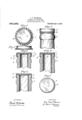
- Figure 1 is a top view of the sealing cap described in Patent No. 888,995, and Fig. 2 an exterior ed e View of the saine.
- Fig. 3 is an exterior sie view of the sealing cap affixed to a bottle head of standard size
- Fig. 4 is a vertical central section of the same.
- Fig. 5 is a view similar to Fig. 4 except that the sealing ca is shown as affixed to a bottle head whic is less in diameter than the standard bottle.
- Fig. 6 is a view similar to Fig. 4 except -that the bottle head to which the sealing cap is aflixed, is larger in dianlcter than the standard bottle.
- Fig. 7 illustrates the to i view of a scaling cap when secured to a' ottle the head of which is not circular, but slightly elliptical in shape..
- l is the crown, 2 the skirt, and a the horizontally -extending corrugated flange at the edge of the skirt.
- the sealing cap is shown as aflixed to a bottle head of standard size, and it will be seen that l the horizontally extending flange a of the sealing cap has been drawn, bent or Iturned down, and the skirt and corrugated flange has become a cylindrical body with the underside of the corrugations of the flange situated under the shoulder Z1 of the bottle head 3. This changed condition of the sealing cap is reduced by the passage over it of the suitab e capping tool.
- a suitablel scalino' head is forced over the loosely capped bottle (or the bottle and cap are forced upwardly into the sealin head) thereby bending the corrugated ange a downwardl until its outer surface is substantially 1n the cylindrical lane of the skirt 2.
- the flange a is thus orced into a circle of less than its original diameter, and as the sealing head confines the cap therein, the surplus metal produced by this contraction of the flange is forced to flow inwardly, and the crests of the corrugation are thereby forced under and into locking enagement with the shoulder of the bottle.
- FIG. 6 shows the locking ange expanded over a head of larger diameter than the standard.
- Fig. 7 illustrates the sealin cap on a bottle having a somewhat elliptica head. In such eases, the corrugations adjacent to the larger diameter of the head and lcap project outwardly to a somewhat greater extent than those adjacent to the shorter diameter. l
- a bottle orother vessel having a head provided with a locking shoulder, and a sealing cap, said cap comprising a crown, a skirt, and a continuously corrugated locking flange forming an extension of the skirt, said flange being bent downwardly on a line forming the junctionbetween the skirt and flange, with ythe corrugations of the iiange forced inwardly underneath said shoulder; substantially as described.
- a bottle 'or other vessel having a head provided lwith a locking shoulder, and a sealing cap, said cap comprising a crown, a skirt, and a continuously corrugated .locking flange, the an e, in its locking position, forming a su stantially vertical extension of the skirt, said ange being circumferentially compressed into a diameter less than its original diameter by bending downwardlyl on a line at the inner ends of thev corrugations, whereby the latter are contracted and forced into locking engagement with said shoulder; substantially as described.
Landscapes
- Engineering & Computer Science (AREA)
- Mechanical Engineering (AREA)
- Closures For Containers (AREA)
Description
E. P. WBTMORE.
SEALING GAP Fon BOTTLES.
APPLICATION IFILED NOV. 5. 1908.
Patented Apr. 5, 1910.
A/lornay4 Mcm. l
' UNITED sTATns T AMTENT oFFIoE.
EARL PORTER WETMORE, OF NEW YORK, N. Y., ASSIGNOR T0 STERLING CORK AND SEAL COMPANY, A CORPORATION OF DELAWARE.
SEALING-CAP FOR BOTTLES.
Specification of Letters Patent.
Patented Apr. 5, 1910.
Application filed November 5, 1908. Serial N o. 461,144.
To all whom 'it may concern:
Be it known that I, EARL PORTER WET- Mone, of the city, county, and State of New York, have invented certain Improvements in Sealing-Caps for Bottles, of which the following is a specification.
This invention relates to an improvement in sealing caps having substantially the construction shown and described in Letters Patent No. 888,995 granted on the twenty sixth day of May, 1908, to Emory J. Godman, to which reference should be made. The sealing cap described in the said patent consists of a crown having a smooth cylindrical skirt which is provided at its edge with a horizontally extending corrugated flange; and .the operation of aflixing the cap to a bottle consists in indenting the skirt on a circular line which is above the .corrugated flange and slightly below or partially underneath the locking shoulder of the bottle head. By an examination of the said sealing cap it will be seen that the skirt above the corrugated flange is flexible, while the flange due to the corrugations, is rigid, and it has been found that 1n any effort to turn downl the horizontally extending flange, the skirt will bend at the junction of the flange With-the smooth cylindrical portion of the cap above it, and the sharp annular corner formed at that point will be thrown inward and the skirt of the cap at that place reduced in diameter to a greater extent than the portion of the skirt immediately above it. This peculiarity discovered in experimen- 1 tally turning down the corrugated ange, is
availed of in the resent invention to produce a more satisfactory closure of bottles without respect to variations in shape of their heads, or differences in diameter within a reasonable limit, as will hereinafter fully appear.
Inlthe further description of the said invention which follows, reference is made to the accompanying drawings, forming a part hereof, and in which,-
Figure 1 is a top view of the sealing cap described in Patent No. 888,995, and Fig. 2 an exterior ed e View of the saine. Fig. 3 is an exterior sie view of the sealing cap affixed to a bottle head of standard size, and Fig. 4 is a vertical central section of the same. Fig. 5 is a view similar to Fig. 4 except that the sealing ca is shown as affixed to a bottle head whic is less in diameter than the standard bottle. Fig. 6 is a view similar to Fig. 4 except -that the bottle head to which the sealing cap is aflixed, is larger in dianlcter than the standard bottle. Fig. 7 illustrates the to i view of a scaling cap when secured to a' ottle the head of which is not circular, but slightly elliptical in shape..
Referring now to l `igs. l and 2 which illustrate the sealing cap described in latcnt No. 888,995, l is the crown, 2 the skirt, and a the horizontally -extending corrugated flange at the edge of the skirt.
Referring now to Figs. 3 and 4 ot' the drawings the sealing cap is shown as aflixed to a bottle head of standard size, and it will be seen that l the horizontally extending flange a of the sealing cap has been drawn, bent or Iturned down, and the skirt and corrugated flange has become a cylindrical body with the underside of the corrugations of the flange situated under the shoulder Z1 of the bottle head 3. This changed condition of the sealing cap is reduced by the passage over it of the suitab e capping tool.
In the bottle-sealing operation, a suitablel scalino' head is forced over the loosely capped bottle (or the bottle and cap are forced upwardly into the sealin head) thereby bending the corrugated ange a downwardl until its outer surface is substantially 1n the cylindrical lane of the skirt 2. The flange a is thus orced into a circle of less than its original diameter, and as the sealing head confines the cap therein, the surplus metal produced by this contraction of the flange is forced to flow inwardly, and the crests of the corrugation are thereby forced under and into locking enagement with the shoulder of the bottle.
win to the corrugations on the flanoe, this ange is considerably stiffer than t e metal in the skirt 2. The line z' where the flange a joins this skirt forms, therefore the natural bending point, and in the ca ping operation, the bend will occur with su stantaal uniformity along this line. This forms the inwardly rojecting ridge or ed e l1, of Fi 5. With bottles havin heads ostandar size, this edge largely sappears as the sealing cap compresses the outer crests of the corrugations inwardly. Vith bottles having heads slightly smaller than the standard, as shown in Fig. 5, this edge h contacts with the locking shoulder on the bottle, and affords a bearing or fulcrum for the head to actl upon in effecting the lock. Fig. 6 shows the locking ange expanded over a head of larger diameter than the standard. Fig. 7 illustrates the sealin cap on a bottle having a somewhat elliptica head. In such eases, the corrugations adjacent to the larger diameter of the head and lcap project outwardly to a somewhat greater extent than those adjacent to the shorter diameter. l
The provision of an initial bending line at the junction of portions of the cap which .a line of substantially uniform resistance.
There is therefore no distortion of the locking angedue to an attempt to bend across the corrugations; but the distortion is wholly that which is due tothe crowding of the metal of the flange into a smaller diameter, and which is utilized to forcethe corrugations iwardl into locking engagement with the shouldier of the bottle. This results in such a close fitting of the lcap to the bottle head at all points as to prevent leakage. The bearing edge 7L also forms such close contact with the bottle as to eifectually exclude small insects from crawling up through the corrugations and attacking the Icork gasket g, a difficulty which has proven a ser1ousone in southern countries with other forms of caps. The bending line of substantially uniform resistance also enablesy the iange a to-stretch to adapt itself to irregular bottle heads (as shown in Fig.' 7,
for instance) in a manner which is not possible with a bend made across the corrugati'ons. By this method of bending, comparativ'el little inward radial pressure is require This obviates to a very large degree the breakage of the bottles, which has occurred with the methods heretofore employed. It also permits of the application of the invention to other vessels besldes botu tles; that is to say, Vessels such as fruit jars, jelly glasses, and like vessels having mouths of relatively large diameters.
I claim as my invent-ion,-
1'. A bottle orother vessel having a head provided with a locking shoulder, and a sealing cap, said cap comprising a crown, a skirt, and a continuously corrugated locking flange forming an extension of the skirt, said flange being bent downwardly on a line forming the junctionbetween the skirt and flange, with ythe corrugations of the iiange forced inwardly underneath said shoulder; substantially as described.
2. A bottle 'or other vessel having a head provided lwith a locking shoulder, and a sealing cap, said cap comprising a crown, a skirt, and a continuously corrugated .locking flange, the an e, in its locking position, forming a su stantially vertical extension of the skirt, said ange being circumferentially compressed into a diameter less than its original diameter by bending downwardlyl on a line at the inner ends of thev corrugations, whereby the latter are contracted and forced into locking engagement with said shoulder; substantially as described.
EARL PGRTER WETMORE.
Witnesses:
'MAE E. DEY, M. J. HOGAN.
Priority Applications (1)
| Application Number | Priority Date | Filing Date | Title |
|---|---|---|---|
| US46114408A US954405A (en) | 1908-11-05 | 1908-11-05 | Sealing-cap for bottles. |
Applications Claiming Priority (1)
| Application Number | Priority Date | Filing Date | Title |
|---|---|---|---|
| US46114408A US954405A (en) | 1908-11-05 | 1908-11-05 | Sealing-cap for bottles. |
Publications (1)
| Publication Number | Publication Date |
|---|---|
| US954405A true US954405A (en) | 1910-04-05 |
Family
ID=3022811
Family Applications (1)
| Application Number | Title | Priority Date | Filing Date |
|---|---|---|---|
| US46114408A Expired - Lifetime US954405A (en) | 1908-11-05 | 1908-11-05 | Sealing-cap for bottles. |
Country Status (1)
| Country | Link |
|---|---|
| US (1) | US954405A (en) |
Cited By (2)
| Publication number | Priority date | Publication date | Assignee | Title |
|---|---|---|---|---|
| US2543775A (en) * | 1949-04-01 | 1951-03-06 | Gora Lee Corp | Container closure |
| US2543774A (en) * | 1949-03-08 | 1951-03-06 | Gora Lee Corp | Container closure |
-
1908
- 1908-11-05 US US46114408A patent/US954405A/en not_active Expired - Lifetime
Cited By (2)
| Publication number | Priority date | Publication date | Assignee | Title |
|---|---|---|---|---|
| US2543774A (en) * | 1949-03-08 | 1951-03-06 | Gora Lee Corp | Container closure |
| US2543775A (en) * | 1949-04-01 | 1951-03-06 | Gora Lee Corp | Container closure |
Similar Documents
| Publication | Publication Date | Title |
|---|---|---|
| US2045480A (en) | Closure for bottles, jars, and similar containers | |
| US1326885A (en) | Nathaniel b | |
| US775651A (en) | Bottle-seal. | |
| US615453A (en) | Stephen hipkins | |
| US343646A (en) | Ments | |
| US3933265A (en) | Bottle closure | |
| US582762A (en) | Bottle-sealing device | |
| US933347A (en) | Jar cap or closure. | |
| US1941712A (en) | Hermetic seal for bottles | |
| US332382A (en) | William e | |
| US822099A (en) | Bottle-cap. | |
| US888995A (en) | Bottle-sealing cap. | |
| US816720A (en) | Closure device for bottles, jars, and other vessels. | |
| US890302A (en) | Jar and bottle closure. | |
| US666673A (en) | Cap-closure for bottles. | |
| US934072A (en) | Means for sealing vessels. | |
| US885571A (en) | Bottle-top. | |
| US1100935A (en) | Bottle-closure device. | |
| US703528A (en) | Bottle-stopper. | |
| US1139792A (en) | Bottle-cap. | |
| US860964A (en) | Bottle-closure. | |
| US661746A (en) | Fruit-jar. | |
| US954406A (en) | Method of sealing bottles and other vessels. | |
| US872403A (en) | Bottle-closure. | |
| US1196228A (en) | Closure for bottles and the like. |