US9544017B2 - Powerline communicated load control - Google Patents
Powerline communicated load control Download PDFInfo
- Publication number
- US9544017B2 US9544017B2 US14/193,405 US201414193405A US9544017B2 US 9544017 B2 US9544017 B2 US 9544017B2 US 201414193405 A US201414193405 A US 201414193405A US 9544017 B2 US9544017 B2 US 9544017B2
- Authority
- US
- United States
- Prior art keywords
- power signal
- voltage
- voltage offset
- instantaneous
- control
- Prior art date
- Legal status (The legal status is an assumption and is not a legal conclusion. Google has not performed a legal analysis and makes no representation as to the accuracy of the status listed.)
- Expired - Fee Related, expires
Links
Images


Classifications
-
- H—ELECTRICITY
- H04—ELECTRIC COMMUNICATION TECHNIQUE
- H04B—TRANSMISSION
- H04B3/00—Line transmission systems
- H04B3/54—Systems for transmission via power distribution lines
- H04B3/542—Systems for transmission via power distribution lines the information being in digital form
-
- H—ELECTRICITY
- H04—ELECTRIC COMMUNICATION TECHNIQUE
- H04B—TRANSMISSION
- H04B3/00—Line transmission systems
- H04B3/54—Systems for transmission via power distribution lines
-
- H—ELECTRICITY
- H04—ELECTRIC COMMUNICATION TECHNIQUE
- H04L—TRANSMISSION OF DIGITAL INFORMATION, e.g. TELEGRAPHIC COMMUNICATION
- H04L27/00—Modulated-carrier systems
- H04L27/02—Amplitude-modulated carrier systems, e.g. using on-off keying; Single sideband or vestigial sideband modulation
-
- H—ELECTRICITY
- H04—ELECTRIC COMMUNICATION TECHNIQUE
- H04L—TRANSMISSION OF DIGITAL INFORMATION, e.g. TELEGRAPHIC COMMUNICATION
- H04L27/00—Modulated-carrier systems
- H04L27/02—Amplitude-modulated carrier systems, e.g. using on-off keying; Single sideband or vestigial sideband modulation
- H04L27/04—Modulator circuits; Transmitter circuits
-
- H—ELECTRICITY
- H04—ELECTRIC COMMUNICATION TECHNIQUE
- H04L—TRANSMISSION OF DIGITAL INFORMATION, e.g. TELEGRAPHIC COMMUNICATION
- H04L27/00—Modulated-carrier systems
- H04L27/02—Amplitude-modulated carrier systems, e.g. using on-off keying; Single sideband or vestigial sideband modulation
- H04L27/06—Demodulator circuits; Receiver circuits
-
- H—ELECTRICITY
- H05—ELECTRIC TECHNIQUES NOT OTHERWISE PROVIDED FOR
- H05B—ELECTRIC HEATING; ELECTRIC LIGHT SOURCES NOT OTHERWISE PROVIDED FOR; CIRCUIT ARRANGEMENTS FOR ELECTRIC LIGHT SOURCES, IN GENERAL
- H05B45/00—Circuit arrangements for operating light-emitting diodes [LED]
- H05B45/10—Controlling the intensity of the light
-
- H—ELECTRICITY
- H05—ELECTRIC TECHNIQUES NOT OTHERWISE PROVIDED FOR
- H05B—ELECTRIC HEATING; ELECTRIC LIGHT SOURCES NOT OTHERWISE PROVIDED FOR; CIRCUIT ARRANGEMENTS FOR ELECTRIC LIGHT SOURCES, IN GENERAL
- H05B47/00—Circuit arrangements for operating light sources in general, i.e. where the type of light source is not relevant
- H05B47/10—Controlling the light source
- H05B47/175—Controlling the light source by remote control
- H05B47/185—Controlling the light source by remote control via power line carrier transmission
-
- H—ELECTRICITY
- H04—ELECTRIC COMMUNICATION TECHNIQUE
- H04B—TRANSMISSION
- H04B2203/00—Indexing scheme relating to line transmission systems
- H04B2203/54—Aspects of powerline communications not already covered by H04B3/54 and its subgroups
- H04B2203/5429—Applications for powerline communications
- H04B2203/5458—Monitor sensor; Alarm systems
Definitions
- the invention relates to the technical of communicating control signals over an AC supply line.
- Load control systems utilizing separate dedicated wiring have been widely employed for energy and comfort management in new commercial buildings.
- costs of adding the required control wiring usually prohibits such load control upgrades to be retrofit to existing buildings.
- a cost-effective wireless system would, however, mitigate the complications of the routing of new wiring that would be required.
- dimming signals that are transmitted by phase-cut manipulation of the power supplied to specially equipped fixtures on an existing lighting branch.
- Philips Advance Transformer Mark X® and Lutron TuWire® ballasts use phase cut manipulation.
- wall-mounted dimmers such as those usually employed for incandescent loads, are then used for manual dimming control with phase cut manipulation. This method has proved very convenient for small areas, but not for wide application because power quality is incrementally reduced by each fixture under such control.
- PLC power line carrier control
- Still another general approach to remote load control uses radio frequency signaling.
- control messages in the form of radio frequency signals are transmitted via a mesh network, where they are handed off sequentially though low-power transceivers located at each control point.
- a low-cost implementation of this approach capable of communicating control messages has been illusive.
- the present invention allows load control signals to be sent over the same wiring that is used to provide AC power to the load. This is particularly applicable to remote lighting control, where the addition of dedicated wiring for lighting control can be costly and time consuming. By using the existing AC supply wiring, the changeover from conventional lighting to is greatly simplified and installation costs are significantly reduced.
- HVAC heating, ventilation and air-conditioning
- the present disclosure provides a system for transmitting communication signals over a powered circuit conductor.
- the system comprises an injector circuit connected to a powered circuit conductor and configured to modulate a power signal with a direct current voltage asymmetrically resulting in a DC offset, the direct current voltage offset being within a range that causes approximately 1 percent or less total harmonic distortion of the power signal; and a decoder connected to the powered circuit conductor and a load, the decoder configured to demodulate the direct current voltage offset to control the load.
- the present disclosure provides a method for transmitting communication signals over a powered circuit conductor.
- the method comprises modulating a power signal on a powered circuit conductor with a direct current voltage asymmetrically resulting in a DC offset, the direct current voltage offset being within a range that causes approximately 1 percent or less total harmonic distortion of the power signal; and demodulating the direct current voltage offset to control a load.
- FIG. 1 is a block diagram for installation of the power line communicated load control system in a single lighting branch
- FIG. 2 is a block diagram for installation of the power line communicated load control system in multiple lighting branches
- FIG. 3 is a schematic for an injector circuit in accordance with one aspect of the invention.
- FIG. 4 is a schematic for an injector circuit accordance with an aspect of the invention.
- FIG. 5 is a schematic for an injector circuit in accordance with an aspect of the invention.
- FIG. 6 is a schematic for an injector circuit in accordance with an exemplary embodiment
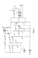
- FIG. 7 is a schematic for a decoder circuit in accordance with an aspect of the invention.
- FIG. 8 is a flow chart showing a method for decoding control signals on a powerline in accordance with the disclosed principles.
- FIG. 9 is a schematic for an isolation interface for a decoder circuit in accordance with the disclosed principles.
- FIG. 10 is a block diagram for adapting PCLC to a light fixture having a 0-10 volt analog ballast or voltage-controlled dimming LED driver;
- FIG. 11 is a block diagram for adapting PCLC to a light fixture having a PWM controlled dimming LED driver or current control;
- FIG. 12 is a block diagram for adapting PCLC to a light fixture having a two-wire dimming fluorescent ballast.
- FIG. 13 is a block diagram for adapting PCLC to a light fixture configured to operate with a three-wire dimming control
- FIG. 14 is a block diagram for adapting PCLC to a light fixture configured to operate with a DALI dimming control.
- the present invention provides a new system and method for communicating load control signals on existing branch power lines.
- Known systems for sending control signals over power lines employ the injection of carrier current signals having a frequency of 100 kHz and higher. These relatively high frequency signals are difficult to propagate over 50 or 60 Hz power lines with their associated loads.
- One aspect of the present invention is to utilize low-frequency supply voltage as a carrier frequency and then modulate the supply voltage signal in accordance with the information to be communicated. Although this approach provides a communication bandwidth of only a fraction of a cycle per second, such speed is adequate for the intended load management application. This technique is referred to as Power line Communicated Load Control (“PCLC”).
- PCLC Power line Communicated Load Control
- PCLC can be used for on/off control of incandescent, fluorescent, light emitting diode (“LED”), high intensity discharge (“HID”) and induction lighting sources. It can also be used to manipulate the dimming level of any of the above light sources that have been equipped for dimming. Although the preferred embodiments will be described in the context of lighting in commercial buildings, it should be understood that PCLC can be applied to all types of fixed electrical loads.
- the PCLC system preferably performs at least two load control actions; load shave and load shed.
- Load shave refers to trimming non-essential components of the total load during periods of the day when the applicable electric rate is at a premium, or during intervals when excessive consumption can trigger an onerous rate escalation for exceeding a prescribed level of peak demand.
- Load shed refers to a response to an indication from the serving utility that it will be experiencing a period of critical capacity shortage during specified upcoming intervals. Such a response may be elective, in order to help avoid a system-wide “brown out” or may be mandatory if the consumer has previously agreed to such a response in return for a favorable billing rate.
- PCLC has a number of benefits when applied to lighting applications.
- PCLC is capable of sending commands down a power line in such a way that they are uniquely confined to the downstream physical limits of that power line. This prevents any undesired command signal bleed onto other lighting branches.
- FIG. 1 is a block diagram for PCLC as installed on a single lighting branch.
- PCLC is preferably comprised of an injector 101 , a system control 102 , and a decoder 103 .
- the system control 102 connects the injector 101 to the network in order to introduce a voltage asymmetry on the AC line conductor.
- the injector 101 is disconnected from the network so as to be lossless.
- the voltage asymmetry on the AC line conductor manifests itself as the presence of a DC bias or offset that is within a range that causes approximately 1% or less total harmonic distortion of the power signal.
- the DC offset is within the rage of 1 to 5 volts.
- Downstream loads are equipped with a decoder 103 to detect the signals introduced by the injector 101 onto the AC line conductor. The decoder 103 decodes the voltage asymmetry into the desired command for use by the load.
- the injector 101 is installed in series with the AC line conductor that supplies the controlled load. Because the injector 101 is installed in series with the AC line conductor, the AC line conductor must be opened for installation.
- the injector 101 is installed at a point on the AC line conductor that is in series with all the loads over which PCLC is to exert control.
- the injector could be installed in series with either an entry wall switch or at a junction box for control of electrical loads in a single room.
- the injector 101 could be installed at the circuit breaker for a branch circuit serving individual plug-in outlets.
- the injector 101 could be installed in the AC line conductor entry to a distribution panel 104 , if all loads served by that distribution panel 104 are to receive the same load control signals.
- the injector 101 could be installed in the AC line conductor entering the main electrical supply panel for an entire facility, if all electrical loads in that facility are to receive the same load control signals. In this case, the injector 101 would preferably be scaled for a higher current capacity.
- FIG. 1 shows some of the locations at which the injector 101 could be installed.
- the system control 102 is typically wired to the injector 101 in order to regulate the introduction of control signals on the power line.
- System control 102 can be installed in a number of locations.
- system control 102 can be installed in a wall-mounted fixture 104 outside the lighting panel as shown in FIG. 1 .
- system control 102 may be installed in the lighting panel near the injector 101 .
- the system control 102 can originate from a number of sources, including, but not limited to: (1) a manual key-switch enabled controller; (2) a programmable time clock; (3) a controller that monitors real-time electric demand, to avoid onerous peak demand excesses; (4) an Ethernet interfaced controller located on the premises; (5) an internet enabled remote control location; or (6) a building wide energy management system.
- a decoder 103 is installed in each lighting fixture 105 in the lighting branch to interpret the control signals on the AC power line.
- FIG. 1 depicts the decoder 103 as separate from the lighting fixture 105 , the decoder 103 can be installed within the lighting fixture 105 itself.
- FIG. 2 shows installation of a PCLC system in a building with multiple lighting branches.
- an injector 201 is installed for each lighting branch.
- the injector 201 is preferably installed in the lighting panel 204 , but may be installed in other locations as well.
- Each injector is fitted with two forms of system control 202 a and 202 b .
- System control 202 a is a switch installed in a wall-mounted fixture and hard-wired to the injector 201 .
- System control 202 b originates from an internet enabled controller.
- System control 202 b can be hard-wired to the injector or it may transmit signals to the injector wirelessly.
- PCLC can be adapted to function in a way that confines the signaling specifically to each branch, by installing a separate injector in each branch circuit. Because the injector delivers the control signal to only downstream components, no unintentional bleeding of the control signal across neighboring branches can occur.
- FIG. 2 depicts a PCLC system where light fixtures 205 are grouped together and provided with an independent occupant control 206 .
- the independent occupant control 206 can be, for example, a wall-mounted light switch located proximal to the light fixtures 205 .
- the independent occupant control connects or disconnects the light fixtures 205 from the branch supply line. When the independent occupant control 206 disconnects the light fixtures 205 from the supply line, no load management controls are needed and the decoder 203 is also disconnected. When the independent occupant control 206 connects the light fixtures to the supply line, the decoders 203 are also connected. This allows decoders 203 to receive command signals on the supply line. Consequently, the PCLC system is able execute load management controls. This is particularly helpful when an occupant forgets to disconnect the light fixtures 205 via the independent occupant control 206 .
- FIG. 2 also illustrates another important advantage of the PCLC system. That is, PCLC can be adapted to operate with varying types of light fixtures. As shown in FIG. 2 , lighting branches often include different types of light fixtures 205 . For example, FIG. 2 includes both 0-10 volt analog lighting ballasts as well as LED drivers. PCLC can be adapted to operate with both. In fact, only the decoder needs modification in order to operate with varying types of light fixtures 205 . Examples of how the decoder 203 can be modified to operate with different light fixtures will be described below.
- FIG. 3 is a schematic for an injector circuit in accordance with one aspect of the invention.
- This network topography temporarily injects an asymmetrical connection of silicon power diodes 302 , 303 , 304 , 305 , 306 in the AC line conductor.
- An electro-mechanical relay 301 is used to connect the injector circuitry to the AC line conductor. When the relay contacts that shunt the injector circuitry are momentarily opened, an asymmetrical control signal is introduced on the AC line conductor. Power losses will occur only during this brief interval. Otherwise the injector circuitry consumes no electrical power.
- an electro-mechanical relay 301 has been described in this embodiment, the same switching functionality could be obtained with a solid-state relay. Such devices typically employ back-to-back MOSFET or IGBT switching elements, which have very low conduction voltage drops.
- the network used in this embodiment has two parallel branches, one branch having multiple series-connected diodes, 302 , 303 , 304 , 305 and 306 , to serve as a current path to the load for one direction and the parallel branch having a single diode 307 producing a lower voltage drop to the load for the other polarity of the AC voltage alternation.
- the net result is to introduce an approximate (n ⁇ 1)*0.65-volt average DC component to the supply voltage that is conducted over the lighting supply branch.
- the DC voltage drop, or voltage offset is within a range that causes approximately 1% or less total harmonic distortion of the power signal.
- the DC voltage offset is in the range of 1 to 5 volts. 1 to 5 volts is large enough to achieve adequate signaling in the presence of interfering noise without significant power quality depreciation during the signaling intervals.
- Silicon diodes are preferred for implementing this embodiment because they are low in cost, readily available, and offer high current ratings. High current ratings are important because all of the current supplied to the downstream loads will flow through this network. For example, a network containing a branch with a 15 ampere lighting load will have to dissipate a momentary loss of several watts. Increasing the number of diodes to increase the DC value of the offset may seem like an attractive design tactic, but doing so will further increase the dissipative loss.
- the injector is preferably installed in locations where the power lines are not otherwise corrupted with loads that can produce an extraneous DC voltage offset. Typically, the presence of such loads in most well-engineered buildings would not be acceptable. In any case, the standard installation practice for dedicated load lighting is to separately power the supply branches independently from plug loads and from other machinery. Lighting branch power quality is further enhanced due to the fact that modern electronic ballasts are mandated to include power factor correction circuitry. These factors help isolate the lighting branch from sources of power quality corruption, that could otherwise create interfering noise that might interfere with the encoded control.
- FIG. 4 is a schematic depicting injector circuitry in accordance with another aspect of the invention.
- An electro-mechanical relay 401 is used to connect the injector circuitry to the AC line conductor.
- the branch containing multiple power diodes is replaced with a junction transistor 402 having its base controlled by a low power Zener diode 403 and a resistor 404 .
- a diode 405 is still preferably used to produce a lower voltage drop in the polarity opposite of that produced by the junction transistor 402 .
- This circuit configuration conveniently consolidates all the power losses of the multiple-drop branch into a single readily available junction transistor 402 .
- the Zener diode 403 current is only a fraction of the load current, since it is effectively multiplied by the current gain of the junction transistor 402 .
- a junction transistor 402 is illustrated, either a MOSFET or IGBT could be employed to provide the active current gain required for the operation of the circuit. This embodiment is beneficial because it tends to be a more cost-effective option.
- an electro-mechanical relay 401 is used to connect the injector circuitry to the AC line conductor.
- an electro-mechanical relay has been described in this embodiment, the same switching functionality could be obtained with a solid-state relay.
- Such devices typically employ back-to-back MOSFET or IGBT switching elements, which have very low conduction voltage drops.
- FIG. 5 is a schematic for an injector in accordance with another aspect of the invention.
- An electro-mechanical relay 505 is used to connect the injector circuitry to the AC line conductor.
- a silicon controlled rectifier (SCR) or a bidirectional triode thyristor (TRIAC) 501 is used to provide a unidirectional voltage drop.
- a diode 504 is preferably used to produce a lower voltage drop in the polarity opposite of that produced by the TRIAC or SCR 501 .
- the network consisting of resistor 502 and capacitor 503 provides excitation for the silicon controlled rectifier's 501 gate to trigger conduction, and imposes a slight phase delay. This delay reduces the unidirectional conduction angle, thus producing the desired DC offset.
- This embodiment is an attractive option because it contains widely available components in the appropriate voltage and current ratings.
- FIG. 6 is a schematic for an injector in accordance with yet another aspect of the invention.
- This injector circuit is comprised of not one, but two asymmetrical diode networks.
- Diode network 603 is configured to produce an average voltage offset in one polarity
- diode network 604 is configured to produce an average voltage offset in the opposite polarity.
- Each of the asymmetrical networks is shunted by a normally closed switch 601 , 602 . If switch 601 is momentarily opened, an average voltage offset of the appropriate polarity will be produced at the line out terminal during the actuation interval. Alternatively, if switch 602 is momentarily operated, an offset of the opposite polarity will result during the actuation interval.
- This injector configuration is referred to as a bi-polar injector. It may be applied in circumstances where complicated encoding is not desired. For example, this embodiment could be applied to produce a rudimentary “dim up” and “dim down” wall control without the needing a complex system control.
- FIG. 7 is a schematic for a decoder used to detect the presence of control signals on an AC power line in accordance with an exemplary embodiment.
- the decoder in FIG. 7 utilizes an initial “Twin Tee” notch filter to attenuate the 60 (or 50) Hz power line frequency component.
- the notch filter is comprised of capacitors 702 , 703 and 706 , as well as resistors 701 , 705 and 704 .
- the “Twin Tee” notch filter is followed by a 2-pole low pass filter to further enhance detection of control signals in the form of momentary intervals of DC offset on the powerline.
- the 2-pole low pass filter is comprised of resistors 707 and 708 and capacitors 709 and 710 .
- Transistor inverters 711 and 712 combined with resistors 713 , 714 and 715 perform impedance transformation and level shifting functions.
- Resistor 717 , diodes 719 , 720 and 722 , and capacitors 718 and 721 serve as an energy-efficient, transformer-less, low-current power supply.
- Resistor 723 limits current to microprocessor 716 pin 6 , and capacitor 724 filters high frequency noise.
- FIG. 8 shows a method that can be used by microprocessor 716 to decode control signals on the powerline.
- the method begins by calculating the average DC bias component on the powerline when no control signal is present (step 810 ). From this average, a pulse threshold is determined (step 820 ).
- the pulse threshold may be, for example, the average value between the amplitude of a control signal pulse and the average DC bias component calculated in step 810 . Averaging the threshold value in this manner provides a reliable way in which to determine a threshold value above the background noise level.
- the microprocessor can then monitor the DC bias present on the powerline in order to detect control pulses (step 830 ).
- the microprocessor 716 If the microprocessor 716 detects a pulse signal greater than the threshold value (step 840 ), the microprocessor 716 will then measure the duration of that pulse (step 850 ). Once the duration of the pulse signal has been determined, the microprocessor 716 will compare the pulse duration measurement to a predetermined pulse duration threshold (step 860 ). If the pulse duration exceeds the pulse duration threshold value, the microprocessor 716 will demodulate the pulse signal into control information based on the selected modulation scheme for the PCLC system.
- control information can be modulated in a number of ways.
- the control information could be modulated in a two-state scheme or a multi-level scheme.
- Two-state schemes are used for basic on/off functionality.
- any pulse that has a duration longer than a predetermined value, for example 500 ms is considered an “off” signal, while any pulse shorter than the predetermined value—but still longer than the pulse duration threshold—is considered an “on” signal.
- a two-state scheme could also be implemented where longer pulses are “on” signals and shorter pulses are “off” signals.
- a multi-level scheme preferably uses pulses of a fixed width, for example 200 ms, and varies the time between the pulses to send multiple bits of binary data. The number of discernable time periods between pulses represents the number of bits of data being sent.
- FIG. 9 shows an isolation circuit used to isolate the decoder output from the powerline in accordance with on aspect of the invention.
- the output from pins 3 and 4 of microprocessor 716 are fed to optocoupler 901 , which provides the necessary isolation.
- optocoupler 901 is connected to a set-reset flip-flop gate created by logic gates 902 and 903 and resistors 904 and 905 .
- Resistor 910 and capacitor 907 filter noise from the set-reset flip-flop output.
- the set-reset flip-flop gate Based upon output from the optocoupler, the set-reset flip-flop gate sends short, low-power trigger pulses to produce a low frequency, pulse-width-modulated source for the dimming control signal.
- the dimming control signal is connected to the dimming control in the light fixture.
- Voltage regulator 906 is used to step down the supply voltage from the light fixture in order to power the set-reset flip-flop gate.
- Capacitors 908 and 909 filter noise from the voltage regulator circuit. This galvanic barrier circuitry is powered from an isolated source of voltage in the fluorescent ballast or LED driver to which it is connected.
- the decoder is designed to operate with a number of well-known lighting fixtures. For instance, remote control of low voltage LED loads is easily accomplished with PCLC technology.
- the drivers used to energize LED loads conveniently have low voltage outputs that can serve to power a decoder as well as the LED load. This is not only cost-effective, but it also simplifies the complexity of UL/CEO certification.
- Several different possible arrangements are presented that are applicable to commercial LED drivers that incorporate either constant current or constant voltage output regulation. In the case of constant voltage, dimming functionality can be added to a driver that does not otherwise have dimming functionality.
- An external pulse width modulation (“PWM”) switch interrupts a variable percentage of the drive current in order to dim the LED load.
- PWM pulse width modulation
- Constant current drivers must include a dimming function if they are to be controlled by a decoder. Dimming constant current drivers often use a PWM digital input that is used to change the duty cycle of the current source located within the driver circuitry.
- FIG. 10 is a block diagram for a configuration for adapting PCLC to a light fixture using a 0-10 volt analog ballast or voltage-controlled dimming LED driver.
- the decoder includes a microprocessor 1001 , a voltage regulator 1002 and an isolated line interface 1003 .
- the line interface 1003 is configured to isolate the microprocessor 1001 from the powerline.
- the voltage regulator 1002 included in this configuration is also isolated from the power line in order to meet UL® certification standards.
- the microprocessor 1001 supplies a 0-10 volt output that can be used to control devices that lack an internal current source 1004 , such as a fluorescent light.
- This configuration can produce either multiple step or continuous load control, depending on the firmware loaded into the microprocessor 1001 .
- This configuration has no artificial lower limits to its control range. It is able to take advantage of the full control range (e.g. 5-100%) of the load to which it is connected.
- FIG. 11 is a block diagram for installing a decoder in a lighting fixture that utilizes a PWM controlled dimming LED driver or current control.
- the decoder includes a microprocessor 1101 , an isolated line interface 1103 and a voltage regulator 1102 .
- the isolated line interface 1103 isolates the microprocessor 1101 from the powerline.
- the voltage regulator 1102 is also isolated from the powerline order to meet UL® certification standards.
- the microprocessor 1101 produces a variable duty-cycle PWM signal that controls the LED 1104 intensity. It results in continuous or step-incremented changes in the luminous output of the controlled LEDs 1104 .
- the frequency of the PWM control signal is 100 to 500 hertz to minimize perceptible flicker and stroboscopic effects.
- the decoder can also be configured to operate with light fixtures using two-wire dimming fluorescent ballasts. These ballasts have become a popular choice for retrofit applications because they offer the ability to add dimming control over existing power wiring. They also operate with many standard wall dimmer controls in a way that is familiar to both occupants and the installation trades. Similarly, it appears that the same type of dimmer controls are finding wider acceptance for the emerging application of LED dimming. In some instances, it may be desirable to have a few 2-wire dimming loads fed by a branch circuit that also serves non-dimming loads.
- FIG. 12 is a block diagram illustrating how PCLC can be adapted to mixed load, two-wire dimming ballasts.
- the decoder configuration in FIG. 12 includes a microprocessor 1201 , a voltage regulator 1202 , and a line interface 1203 .
- the voltage regulator receives power from the branch supply line.
- Line interface 1203 ensures that the decoder is isolated from the power line for certification purposes.
- the microprocessor 1201 receives control signals sent on the power line, and decodes them into the appropriate load management controls.
- the microprocessor then controls the TRIAC dimmer 1204 which limits power to the controlled the load 1205 .
- the decoder can also be adapted to operate with three-wire dimming ballasts.
- the third wire of three-wire dimming ballasts emanates from a conventional phase-cut wall dimmer that is connected in tandem to each controlled load. This third wire carries only dimming information but not the excitation for the ballast. This reduces the amount of power quality degradation that is introduced from the dimmed load and permits dimming down to very low levels.
- PCLC recovers the commands sent over the power line, as shown in FIG. 13 .
- the decoder configuration in FIG. 13 is very similar to the decoder configuration of FIG. 12 . It consists of a microprocessor 1301 , a voltage regulator 1302 , and a line interface 1303 .
- the decoder configuration replaces a conventional phase-cut wall dimmer that is connected in tandem the load.
- the voltage regulator receives power from the branch supply line.
- Line interface 1303 ensures that the decoder is isolated from the power line for certification purposes.
- the microprocessor 1301 receives control signals sent on the power line, as opposed to signals coming from the phase-cut wall dimmer, and decodes them into the appropriate load management controls.
- the microprocessor controls operation of the TRIAC dimmer 1304 used to control the load 1305 .
- FIG. 14 is a block diagram for a decoder configured to operate with a light fixture that is equipped with a DALI control input. This configuration consists of a microprocessor 1401 programmed with specific DALI commands, a switching universal voltage supply 1402 , and a line interface 1403 . Typically, this variety of control would be used in an addressable network spanning a large number of independent zones. However, in a non-networked application, only one ballast or driver is being controlled.
- DALI Digital Addressable Lighting Interface
- the decoder can take advantage of a special DALI routine, designated as “broadcast mode.”
- This routine transmits commands that are directed to any connected ballast or driver, regardless of its address setting. These commands are transmitted in a simplex mode, which does not require the return of an acknowledgement.
- the microprocessor 1401 can receive the commands and convert them into dimming commands for light fixture.
- the microprocessor 1401 has a random access memory with a sequence of permanently coded DALI commands representing the graduated range of dimming commands.
- the microprocessor 1401 sends the appropriate command to the load with the DALI control input 1404 . It is even possible to implement on/off functionality in this configuration by using the lowest dimming level to turn off the load.
- PCLC adapted to operate with a light fixture having a DALI control input is capable of producing the largest (and most apparent) incremental reduction in a managed load.
- the decoder for this embodiment may be designed to utilize either solid-state (wet contact) or electro-mechanical (dry contact) load relay switches.
- electro-mechanical relay either pulse-actuated or continuously energized types can be employed. Pulse actuated relays are considered preferable from an energy conservation basis, due to the fact that they consume power only when changing switching state. Solid-state relays may also be used. Their relatively low holding currents make them efficient from an energy loss standpoint. The random phase switching variety of solid-state relay is preferable because it does not exhibit triggering anomalies due to holding current complications.
Abstract
Description
V=n*0.65-volts (where N is the number of diodes in the multiple diode leg)
and a single 0.65 voltage drop in the other direction. The net result is to introduce an approximate (n−1)*0.65-volt average DC component to the supply voltage that is conducted over the lighting supply branch. The DC voltage drop, or voltage offset, is within a range that causes approximately 1% or less total harmonic distortion of the power signal. Preferably, the DC voltage offset is in the range of 1 to 5 volts. 1 to 5 volts is large enough to achieve adequate signaling in the presence of interfering noise without significant power quality depreciation during the signaling intervals.
Claims (22)
Priority Applications (1)
| Application Number | Priority Date | Filing Date | Title |
|---|---|---|---|
| US14/193,405 US9544017B2 (en) | 2011-07-28 | 2014-02-28 | Powerline communicated load control |
Applications Claiming Priority (3)
| Application Number | Priority Date | Filing Date | Title |
|---|---|---|---|
| US201161574073P | 2011-07-28 | 2011-07-28 | |
| US13/559,241 US8716882B2 (en) | 2011-07-28 | 2012-07-26 | Powerline communicated load control |
| US14/193,405 US9544017B2 (en) | 2011-07-28 | 2014-02-28 | Powerline communicated load control |
Related Parent Applications (1)
| Application Number | Title | Priority Date | Filing Date |
|---|---|---|---|
| US13/559,241 Continuation US8716882B2 (en) | 2011-07-28 | 2012-07-26 | Powerline communicated load control |
Publications (2)
| Publication Number | Publication Date |
|---|---|
| US20140175866A1 US20140175866A1 (en) | 2014-06-26 |
| US9544017B2 true US9544017B2 (en) | 2017-01-10 |
Family
ID=47626942
Family Applications (2)
| Application Number | Title | Priority Date | Filing Date |
|---|---|---|---|
| US13/559,241 Active - Reinstated US8716882B2 (en) | 2011-07-28 | 2012-07-26 | Powerline communicated load control |
| US14/193,405 Expired - Fee Related US9544017B2 (en) | 2011-07-28 | 2014-02-28 | Powerline communicated load control |
Family Applications Before (1)
| Application Number | Title | Priority Date | Filing Date |
|---|---|---|---|
| US13/559,241 Active - Reinstated US8716882B2 (en) | 2011-07-28 | 2012-07-26 | Powerline communicated load control |
Country Status (1)
| Country | Link |
|---|---|
| US (2) | US8716882B2 (en) |
Cited By (2)
| Publication number | Priority date | Publication date | Assignee | Title |
|---|---|---|---|---|
| US10750601B1 (en) * | 2019-10-01 | 2020-08-18 | Abl Ip Holding Llc | Lighting fixture commissioning based on powerline signaling techniques |
| US10841995B1 (en) * | 2020-01-28 | 2020-11-17 | Abl Ip Holding Llc | Transmission circuit for powerline commissioning techniques |
Families Citing this family (25)
| Publication number | Priority date | Publication date | Assignee | Title |
|---|---|---|---|---|
| CN103428953B (en) | 2012-05-17 | 2016-03-16 | 昂宝电子(上海)有限公司 | For the system and method utilizing system controller to carry out brightness adjustment control |
| CN103024994B (en) | 2012-11-12 | 2016-06-01 | 昂宝电子(上海)有限公司 | Use dimming control system and the method for TRIAC dimmer |
| US9548794B2 (en) | 2013-05-03 | 2017-01-17 | Cooper Technologies Company | Power factor correction for constant current input with power line communication |
| US9716466B2 (en) | 2014-01-23 | 2017-07-25 | Lg Electronics Inc. | Power conversion apparatus, photovoltaic module and communication device and photovoltaic system including the same |
| CN103957634B (en) | 2014-04-25 | 2017-07-07 | 广州昂宝电子有限公司 | Illuminator and its control method |
| CN104066254B (en) | 2014-07-08 | 2017-01-04 | 昂宝电子(上海)有限公司 | TRIAC dimmer is used to carry out the system and method for intelligent dimming control |
| JP6508464B2 (en) * | 2015-04-08 | 2019-05-08 | パナソニックIpマネジメント株式会社 | LIGHTING SYSTEM, CONTROL METHOD, AND CONTROL DEVICE |
| US9918373B2 (en) * | 2015-10-14 | 2018-03-13 | The Watt Stopper, Inc. | Methods and apparatus for providing DC power for low voltage lighting |
| CN106413189B (en) | 2016-10-17 | 2018-12-28 | 广州昂宝电子有限公司 | Use the intelligence control system relevant to TRIAC light modulator and method of modulated signal |
| CN206640830U (en) * | 2017-02-17 | 2017-11-14 | 翰力斯有限公司 | A kind of control system of indoor power line transmission |
| CN107317602A (en) * | 2017-05-16 | 2017-11-03 | 北山网电电力技术(北京)有限公司 | Power line carrier communication data transmission method based on QoS service quality |
| EP3622783A4 (en) * | 2017-06-26 | 2020-07-15 | Tridonic GmbH & Co. KG | Controlling system and controlling method |
| CN107645804A (en) | 2017-07-10 | 2018-01-30 | 昂宝电子(上海)有限公司 | System for LED switch control |
| CN107682953A (en) | 2017-09-14 | 2018-02-09 | 昂宝电子(上海)有限公司 | LED illumination System and its control method |
| CN107995730B (en) | 2017-11-30 | 2020-01-07 | 昂宝电子(上海)有限公司 | System and method for phase-based control in connection with TRIAC dimmers |
| CN108200685B (en) | 2017-12-28 | 2020-01-07 | 昂宝电子(上海)有限公司 | LED lighting system for silicon controlled switch control |
| CN109922564B (en) | 2019-02-19 | 2023-08-29 | 昂宝电子(上海)有限公司 | Voltage conversion system and method for TRIAC drive |
| US20210025615A1 (en) * | 2019-07-26 | 2021-01-28 | Carrier Corporation | Communications interface for hvac components |
| CN110493913B (en) | 2019-08-06 | 2022-02-01 | 昂宝电子(上海)有限公司 | Control system and method for silicon controlled dimming LED lighting system |
| CN110831295B (en) | 2019-11-20 | 2022-02-25 | 昂宝电子(上海)有限公司 | Dimming control method and system for dimmable LED lighting system |
| CN110831289B (en) | 2019-12-19 | 2022-02-15 | 昂宝电子(上海)有限公司 | LED drive circuit, operation method thereof and power supply control module |
| KR20210082979A (en) | 2019-12-26 | 2021-07-06 | 삼성전자주식회사 | Mobile Device, and method of operating the mobile device |
| CN111031635B (en) | 2019-12-27 | 2021-11-30 | 昂宝电子(上海)有限公司 | Dimming system and method for LED lighting system |
| CN111432526B (en) | 2020-04-13 | 2023-02-21 | 昂宝电子(上海)有限公司 | Control system and method for power factor optimization of LED lighting systems |
| CN112556105B (en) * | 2020-12-09 | 2022-05-31 | 广东美的暖通设备有限公司 | Control method, control device, communication system and storage medium for communication equipment |
Citations (42)
| Publication number | Priority date | Publication date | Assignee | Title |
|---|---|---|---|---|
| US3944743A (en) | 1974-01-07 | 1976-03-16 | Plantronics, Inc. | Method and apparatus for feedback suppression |
| US4157535A (en) | 1977-05-20 | 1979-06-05 | Lynes, Inc. | Down hole pressure/temperature gage connect/disconnect method and apparatus |
| US5032829A (en) * | 1987-09-16 | 1991-07-16 | Sharp Kabushiki Kaisha | Thin film el display device |
| US5515038A (en) | 1993-11-15 | 1996-05-07 | Camco International Inc. | Data transmission system |
| US6181082B1 (en) | 1998-10-15 | 2001-01-30 | Electro-Mag International, Inc. | Ballast power control circuit |
| US6218787B1 (en) | 1998-04-20 | 2001-04-17 | Jrs Technology Inc. | Remote dimming control system for a fluorescent ballast utilizing existing building wiring |
| US6377163B1 (en) | 2000-09-21 | 2002-04-23 | Home Touch Lighting Systems Llc | Power line communication circuit |
| US20020128009A1 (en) | 2001-02-20 | 2002-09-12 | Erik Boch | Transceiver for fixed wireless access network applications |
| US20030189495A1 (en) | 2002-04-03 | 2003-10-09 | Pettler Peter R. | Method and system for controlling a selected electrical load in a building |
| US6734784B1 (en) | 2000-09-06 | 2004-05-11 | Marshall E. Lester | Zero crossing based powerline pulse position modulated communication system |
| US7023324B2 (en) | 2002-01-24 | 2006-04-04 | Matsushita Electric Industrial Co., Ltd. | Power-line carrier communication apparatus |
| US20060284728A1 (en) | 2005-06-21 | 2006-12-21 | The Regents Of The University Of California | Pulse width modulation data transfer over commercial and residential power lines method, transmitter and receiver apparatus |
| US7183900B2 (en) | 2001-12-20 | 2007-02-27 | Avago Technologies General Ip (Singapore) Pte. Ltd. | Coupling circuit arrangement for data communication over power lines |
| US20070273335A1 (en) | 2000-01-04 | 2007-11-29 | Duff William B Jr | Method and Circuit for Using Polarized Device in AC Applications |
| US7391168B1 (en) | 2005-01-13 | 2008-06-24 | Universal Lighting Technologies, Inc. | Digital control of electronic ballasts using AC power lines as a communication medium |
| US20080157939A1 (en) * | 2006-12-29 | 2008-07-03 | Sehat Sutardja | Power control device |
| US20080191637A1 (en) | 2004-09-24 | 2008-08-14 | Pettler Peter R | Method and apparatus for controlling electrical lighting installations |
| US20080258882A1 (en) | 2007-04-17 | 2008-10-23 | Marshall Lester | Powerline control system and method |
| US20080278295A1 (en) | 2006-01-13 | 2008-11-13 | Mckenzie Philip | System and method for power line carrier communication using high frequency tone bursts |
| US20080309263A1 (en) * | 2007-06-13 | 2008-12-18 | Wen Yuanhong | Method and device for controlling power car window lift |
| US20090039854A1 (en) | 2007-08-09 | 2009-02-12 | Lutron Electronics Co., Inc. | Load control device having a gate current sensing circuit |
| US7541941B2 (en) | 2007-03-16 | 2009-06-02 | Greenbox Technology Inc. | System and method for monitoring and estimating energy resource consumption |
| US7639598B2 (en) | 2006-01-31 | 2009-12-29 | Szabolcs Sovenyi | Simultaneous full-duplex communication over a single electrical conductor |
| US7688183B2 (en) | 2004-04-22 | 2010-03-30 | Powerline Control Systems, Inc. | Powerline pulse position modulated transmitter apparatus and method |
| JP2010205733A (en) | 2009-03-05 | 2010-09-16 | Universal Lighting Technologies Inc | New inexpensive power line communication control device and receiver for discharge lighting ballast having high resistance to noise |
| US20110016063A1 (en) | 2009-07-17 | 2011-01-20 | Gridpoint, Inc. | System and methods for smart charging techniques |
| US20110032085A1 (en) | 2009-08-07 | 2011-02-10 | General Electric Company | Apparatus for controlling integrated lighting ballasts in a series scheme |
| US20110043124A1 (en) * | 2008-04-30 | 2011-02-24 | Koninklijke Philips Electronics N.V. | Methods and apparatus for encoding information on an a.c. line voltage |
| US7912139B2 (en) | 2006-04-03 | 2011-03-22 | Panasonic Corporation | Multi-carrier communication apparatus, power line communication circuit, and multi-carrier communication method |
| US7982633B2 (en) | 2004-07-05 | 2011-07-19 | Schlumberger Technology Corporation | Data communication and power supply system for downhole applications |
| US8006105B1 (en) * | 2006-08-02 | 2011-08-23 | American Megatrends, Inc. | AC-powered in-wall computing device with power-line networking capabilities |
| US20110222595A1 (en) * | 2010-03-10 | 2011-09-15 | Choi In Sook | Power line communication method for transmitting data signal with splitting of power transmission interval |
| US8051309B2 (en) | 2008-08-29 | 2011-11-01 | Hewlett-Packard Development Company, L.P. | Method and apparatus to combine power and control signals in a mobile computing device |
| US8068937B2 (en) | 2008-02-09 | 2011-11-29 | Stephen Spencer Eaves | Power distribution system with fault protection using energy packet confirmation |
| US8068014B2 (en) | 2005-06-06 | 2011-11-29 | Lutron Electronics Co., Inc. | System for control of lights and motors |
| US8107516B2 (en) | 2009-08-28 | 2012-01-31 | Enphase Energy, Inc. | Power line communications apparatus |
| US8116714B2 (en) | 2007-03-14 | 2012-02-14 | Northern Microdesign, Inc. | Use of powerlines for transmission of high frequency signals |
| US8130084B2 (en) | 2007-04-30 | 2012-03-06 | International Business Machines Corporation | Fault tolerant closed system control using power line communication |
| US8138622B2 (en) | 2007-07-18 | 2012-03-20 | Baker Hughes Incorporated | System and method for an AC powered downhole gauge with capacitive coupling |
| US20120091915A1 (en) | 2010-10-19 | 2012-04-19 | General Electric Company | Power line communication method and apparatus for lighting control |
| US20120092141A1 (en) * | 2009-03-06 | 2012-04-19 | Panasonic Corporation | Power supply device |
| US8208235B2 (en) | 2009-09-04 | 2012-06-26 | Lutron Electronics Co., Inc. | Method of detecting a fault condition of a load control device |
-
2012
- 2012-07-26 US US13/559,241 patent/US8716882B2/en active Active - Reinstated
-
2014
- 2014-02-28 US US14/193,405 patent/US9544017B2/en not_active Expired - Fee Related
Patent Citations (45)
| Publication number | Priority date | Publication date | Assignee | Title |
|---|---|---|---|---|
| US3944743A (en) | 1974-01-07 | 1976-03-16 | Plantronics, Inc. | Method and apparatus for feedback suppression |
| US4157535A (en) | 1977-05-20 | 1979-06-05 | Lynes, Inc. | Down hole pressure/temperature gage connect/disconnect method and apparatus |
| US5032829A (en) * | 1987-09-16 | 1991-07-16 | Sharp Kabushiki Kaisha | Thin film el display device |
| US5515038A (en) | 1993-11-15 | 1996-05-07 | Camco International Inc. | Data transmission system |
| US6218787B1 (en) | 1998-04-20 | 2001-04-17 | Jrs Technology Inc. | Remote dimming control system for a fluorescent ballast utilizing existing building wiring |
| US6181082B1 (en) | 1998-10-15 | 2001-01-30 | Electro-Mag International, Inc. | Ballast power control circuit |
| US20070273335A1 (en) | 2000-01-04 | 2007-11-29 | Duff William B Jr | Method and Circuit for Using Polarized Device in AC Applications |
| US7521900B2 (en) | 2000-01-04 | 2009-04-21 | Duff Jr William B | Method and assembly for insulating polarized device |
| US6734784B1 (en) | 2000-09-06 | 2004-05-11 | Marshall E. Lester | Zero crossing based powerline pulse position modulated communication system |
| USRE41739E1 (en) | 2000-09-06 | 2010-09-21 | Powerline Control Systems, Inc. | Synchronization/reference pulse-based powerline pulse position modulated communication system |
| US6784790B1 (en) | 2000-09-06 | 2004-08-31 | Marshall E. Lester | Synchronization/reference pulse-based powerline pulse position modulated communication system |
| US6377163B1 (en) | 2000-09-21 | 2002-04-23 | Home Touch Lighting Systems Llc | Power line communication circuit |
| US20020128009A1 (en) | 2001-02-20 | 2002-09-12 | Erik Boch | Transceiver for fixed wireless access network applications |
| US7183900B2 (en) | 2001-12-20 | 2007-02-27 | Avago Technologies General Ip (Singapore) Pte. Ltd. | Coupling circuit arrangement for data communication over power lines |
| US7023324B2 (en) | 2002-01-24 | 2006-04-04 | Matsushita Electric Industrial Co., Ltd. | Power-line carrier communication apparatus |
| US20030189495A1 (en) | 2002-04-03 | 2003-10-09 | Pettler Peter R. | Method and system for controlling a selected electrical load in a building |
| US7688183B2 (en) | 2004-04-22 | 2010-03-30 | Powerline Control Systems, Inc. | Powerline pulse position modulated transmitter apparatus and method |
| US7982633B2 (en) | 2004-07-05 | 2011-07-19 | Schlumberger Technology Corporation | Data communication and power supply system for downhole applications |
| US20080191637A1 (en) | 2004-09-24 | 2008-08-14 | Pettler Peter R | Method and apparatus for controlling electrical lighting installations |
| US7391168B1 (en) | 2005-01-13 | 2008-06-24 | Universal Lighting Technologies, Inc. | Digital control of electronic ballasts using AC power lines as a communication medium |
| US8068014B2 (en) | 2005-06-06 | 2011-11-29 | Lutron Electronics Co., Inc. | System for control of lights and motors |
| US20060284728A1 (en) | 2005-06-21 | 2006-12-21 | The Regents Of The University Of California | Pulse width modulation data transfer over commercial and residential power lines method, transmitter and receiver apparatus |
| US20080278295A1 (en) | 2006-01-13 | 2008-11-13 | Mckenzie Philip | System and method for power line carrier communication using high frequency tone bursts |
| US7639598B2 (en) | 2006-01-31 | 2009-12-29 | Szabolcs Sovenyi | Simultaneous full-duplex communication over a single electrical conductor |
| US7912139B2 (en) | 2006-04-03 | 2011-03-22 | Panasonic Corporation | Multi-carrier communication apparatus, power line communication circuit, and multi-carrier communication method |
| US8006105B1 (en) * | 2006-08-02 | 2011-08-23 | American Megatrends, Inc. | AC-powered in-wall computing device with power-line networking capabilities |
| US20080157939A1 (en) * | 2006-12-29 | 2008-07-03 | Sehat Sutardja | Power control device |
| US8116714B2 (en) | 2007-03-14 | 2012-02-14 | Northern Microdesign, Inc. | Use of powerlines for transmission of high frequency signals |
| US7541941B2 (en) | 2007-03-16 | 2009-06-02 | Greenbox Technology Inc. | System and method for monitoring and estimating energy resource consumption |
| US20080258882A1 (en) | 2007-04-17 | 2008-10-23 | Marshall Lester | Powerline control system and method |
| US8130084B2 (en) | 2007-04-30 | 2012-03-06 | International Business Machines Corporation | Fault tolerant closed system control using power line communication |
| US20080309263A1 (en) * | 2007-06-13 | 2008-12-18 | Wen Yuanhong | Method and device for controlling power car window lift |
| US8138622B2 (en) | 2007-07-18 | 2012-03-20 | Baker Hughes Incorporated | System and method for an AC powered downhole gauge with capacitive coupling |
| US20090039854A1 (en) | 2007-08-09 | 2009-02-12 | Lutron Electronics Co., Inc. | Load control device having a gate current sensing circuit |
| US8068937B2 (en) | 2008-02-09 | 2011-11-29 | Stephen Spencer Eaves | Power distribution system with fault protection using energy packet confirmation |
| US20110043124A1 (en) * | 2008-04-30 | 2011-02-24 | Koninklijke Philips Electronics N.V. | Methods and apparatus for encoding information on an a.c. line voltage |
| US8051309B2 (en) | 2008-08-29 | 2011-11-01 | Hewlett-Packard Development Company, L.P. | Method and apparatus to combine power and control signals in a mobile computing device |
| JP2010205733A (en) | 2009-03-05 | 2010-09-16 | Universal Lighting Technologies Inc | New inexpensive power line communication control device and receiver for discharge lighting ballast having high resistance to noise |
| US20120092141A1 (en) * | 2009-03-06 | 2012-04-19 | Panasonic Corporation | Power supply device |
| US20110016063A1 (en) | 2009-07-17 | 2011-01-20 | Gridpoint, Inc. | System and methods for smart charging techniques |
| US20110032085A1 (en) | 2009-08-07 | 2011-02-10 | General Electric Company | Apparatus for controlling integrated lighting ballasts in a series scheme |
| US8107516B2 (en) | 2009-08-28 | 2012-01-31 | Enphase Energy, Inc. | Power line communications apparatus |
| US8208235B2 (en) | 2009-09-04 | 2012-06-26 | Lutron Electronics Co., Inc. | Method of detecting a fault condition of a load control device |
| US20110222595A1 (en) * | 2010-03-10 | 2011-09-15 | Choi In Sook | Power line communication method for transmitting data signal with splitting of power transmission interval |
| US20120091915A1 (en) | 2010-10-19 | 2012-04-19 | General Electric Company | Power line communication method and apparatus for lighting control |
Non-Patent Citations (1)
| Title |
|---|
| Konnex PL132-Power-Line-Communication using the CENELEC-C-Band, 2000, 2003, DOMOLOGIC Home Automation GmbH. |
Cited By (3)
| Publication number | Priority date | Publication date | Assignee | Title |
|---|---|---|---|---|
| US10750601B1 (en) * | 2019-10-01 | 2020-08-18 | Abl Ip Holding Llc | Lighting fixture commissioning based on powerline signaling techniques |
| US11160155B2 (en) | 2019-10-01 | 2021-10-26 | Abl Ip Holding Llc | Lighting fixture commissioning based on powerline signaling techniques |
| US10841995B1 (en) * | 2020-01-28 | 2020-11-17 | Abl Ip Holding Llc | Transmission circuit for powerline commissioning techniques |
Also Published As
| Publication number | Publication date |
|---|---|
| US20140175866A1 (en) | 2014-06-26 |
| US8716882B2 (en) | 2014-05-06 |
| US20130034172A1 (en) | 2013-02-07 |
Similar Documents
| Publication | Publication Date | Title |
|---|---|---|
| US9544017B2 (en) | Powerline communicated load control | |
| US11540379B2 (en) | Digital load control system providing power and communication via existing power wiring | |
| US8217589B2 (en) | Method for transmitting control information from a control device to a lamp unit as well as a corresponding illuminating system, lamp unit and control device | |
| US8207687B1 (en) | Dimmable driver circuits for light emitting diodes | |
| US20130162158A1 (en) | Circuit Assembly and Method for Operating at Least one LED | |
| CN102036458A (en) | Phase control dimming compatible lighting systems | |
| GB2482946A (en) | Dimmer output emulation | |
| CN112673711B (en) | Driving circuit of light-emitting diode light source | |
| US10143056B2 (en) | Outdoor lighting system controlled using motion sensor interface | |
| CN104582142A (en) | Unlimited dimming control method of lighting syste | |
| KR101484963B1 (en) | Dimming Control Apparatus For LED Stage Lighting System Using Hybrid Control Mode | |
| US9035571B2 (en) | Electronic ballast with dimming circuit | |
| WO2008053501A1 (en) | A circuit for driving light sources and related method | |
| RU2598321C2 (en) | Method of generating datagrams to control at least one load module or lamp through load line | |
| KR101137824B1 (en) | Lamp Control System and its method With Power Line Communication | |
| US11083071B2 (en) | Method for monitoring power consumption of a load coupled to a power switch | |
| US8547029B2 (en) | Dimmable instant start ballast | |
| US10333586B2 (en) | Lamp power line communication | |
| CN104582141A (en) | Centralized dimming control method of lighting system | |
| WO2008114106A2 (en) | Method and system for adjusting the luminous flux of lamps | |
| AU2016218927A1 (en) | Dimmer system | |
| RU2590894C2 (en) | System for control of lighting installation | |
| CN114616924A (en) | LED driver with PFC and wired bus interface | |
| KR20120128098A (en) | Bi-level lamp ballast |
Legal Events
| Date | Code | Title | Description |
|---|---|---|---|
| AS | Assignment |
Owner name: POWERLINE LOAD CONTROL LLC, NEW YORK Free format text: ASSIGNMENT OF ASSIGNORS INTEREST;ASSIGNORS:PETTLER, PETER R.;FOX, CHRISTOPHER;SIGNING DATES FROM 20120913 TO 20121116;REEL/FRAME:040101/0641 |
|
| STCF | Information on status: patent grant |
Free format text: PATENTED CASE |
|
| AS | Assignment |
Owner name: NEXTGEN LIGHTING, LLC, NEW YORK Free format text: SECURITY INTEREST;ASSIGNOR:POWERLINE LOAD CONTROL, LLC;REEL/FRAME:042911/0278 Effective date: 20170110 Owner name: PIRASTEH, ROSS, NEW YORK Free format text: SECURITY INTEREST;ASSIGNOR:POWERLINE LOAD CONTROL, LLC;REEL/FRAME:042911/0319 Effective date: 20170110 Owner name: NEXTGEN LIGHTING, LLC, NEW YORK Free format text: SECURITY INTEREST;ASSIGNOR:POWERLINE LOAD CONTROL, LLC;REEL/FRAME:042911/0319 Effective date: 20170110 |
|
| FEPP | Fee payment procedure |
Free format text: MAINTENANCE FEE REMINDER MAILED (ORIGINAL EVENT CODE: REM.); ENTITY STATUS OF PATENT OWNER: LARGE ENTITY |
|
| LAPS | Lapse for failure to pay maintenance fees |
Free format text: PATENT EXPIRED FOR FAILURE TO PAY MAINTENANCE FEES (ORIGINAL EVENT CODE: EXP.); ENTITY STATUS OF PATENT OWNER: LARGE ENTITY |
|
| STCH | Information on status: patent discontinuation |
Free format text: PATENT EXPIRED DUE TO NONPAYMENT OF MAINTENANCE FEES UNDER 37 CFR 1.362 |
|
| FP | Lapsed due to failure to pay maintenance fee |
Effective date: 20210110 |