US954088A - Inking mechanism for printing-presses. - Google Patents
Inking mechanism for printing-presses. Download PDFInfo
- Publication number
- US954088A US954088A US49728809A US1909497288A US954088A US 954088 A US954088 A US 954088A US 49728809 A US49728809 A US 49728809A US 1909497288 A US1909497288 A US 1909497288A US 954088 A US954088 A US 954088A
- Authority
- US
- United States
- Prior art keywords
- pipe
- pipes
- shaft
- valve
- inking
- Prior art date
- Legal status (The legal status is an assumption and is not a legal conclusion. Google has not performed a legal analysis and makes no representation as to the accuracy of the status listed.)
- Expired - Lifetime
Links
Images
Classifications
-
- B—PERFORMING OPERATIONS; TRANSPORTING
- B41—PRINTING; LINING MACHINES; TYPEWRITERS; STAMPS
- B41F—PRINTING MACHINES OR PRESSES
- B41F31/00—Inking arrangements or devices
- B41F31/15—Devices for moving vibrator-rollers
-
- Y—GENERAL TAGGING OF NEW TECHNOLOGICAL DEVELOPMENTS; GENERAL TAGGING OF CROSS-SECTIONAL TECHNOLOGIES SPANNING OVER SEVERAL SECTIONS OF THE IPC; TECHNICAL SUBJECTS COVERED BY FORMER USPC CROSS-REFERENCE ART COLLECTIONS [XRACs] AND DIGESTS
- Y10—TECHNICAL SUBJECTS COVERED BY FORMER USPC
- Y10S—TECHNICAL SUBJECTS COVERED BY FORMER USPC CROSS-REFERENCE ART COLLECTIONS [XRACs] AND DIGESTS
- Y10S101/00—Printing
- Y10S101/38—Means for axially reciprocating inking rollers
Definitions
- My invention relates to improvements in inking mechanism forv printing presses
- the inking rollers of printing mechanisms which operate upon the ink drum and printing platesare covered with what is known as composition and are arranged so as to rotate on the ink drum and at the same time are given a vibratory mot-ion longitudinally of the drum.
- This causes friction between the parts, causing both the inking drum and .the composition of the rollers. to become heated in operation.
- This heating injuriously affects the composition on the rollers and softens it, which very seriously shortens the life of" the rollers. So susceptible is this composition to heat thatin hot weather or in hot press rooms the rollers wear out much more rapidly through the heating than in a colder atmosphere.
- My-inventlon therefore relates to 1nechanism which will keep the rollers cool during their operation by discharging upon the rollers, either constantly or at suitable intervals, a blast. orblasts of cold air, and also of the impression cylinders of' the press.
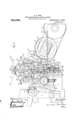
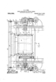
- I Fig. 2 is an elevation of'the inking mechan ism seen from one end of the press.
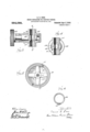
- Fig. 3' is an enlarged detail, being a longitudinal section through the controlling valve.
- Fig. 4 is a section on line 44; of Fig. 3.
- Fig. 5 is a detail, being a cross section through the ink drum, showing the coring out of the same to provide passages for the cold air.
- Fig. 6 is across section of one of the dis- GOSS PRINTING PRESS COM- charge pipes, showing the orifices through which the air is discharged upon the composition rollers.
- FIG. 10 indicates the'ink drum, which, as is best shown in Fig. 5, is cored out so as to have hollow spaces 1l within its periphery whichare closed at each end by the usual heads of the cylinder and adapted to receive a supply of cold air from the pipes hereinafter described.
- the fountain and the feed inkingroller' form no part of my present inventi'onand may be operated in any well-known man ner, itis enough to say that they may be operated in any well-known manner, as by cams 14 on the drivin shafts 15, operating upon'one arm of the evers 16, and by eccentric-rods 17 on the shafts 15 and ratchetwheels and pawls1819.
- the shafts 15 are driven by worms 20 which are driven by worm-gears 21 upon the shaft 22, which, by means of a gear 23 is driven byJthe gear-2 1 on the shaft 25 of, the ink drum 10.
- ink drum in its turn is driven by the usual the shaftofthe impression cylinder-8', and intermediate and 26.
- 3334 indicate form rollers which serve to convey the ink from the ink drum 10 to the plate cylinder 8 and are mounted and operate in the "usual manner.
- valve 37 indicates a valve which is interposed gear 42 by the rotation of which by the mechanism hereinafter described the valve is opened or closed.
- valve 40 will be opened or closed.
- valves in the pipe 36 which are operated by hand-levers 5859, respectively.
- the 60 indicates pipes which are connected by the usual couplings 61 with the upright pipe 36 and with another upright pipe 62 upon the other side of the machlne corresponding to the upright pipe 36. These pipes 60 are also supported by means of rods 63 in brackets 64 supported upon the upper ends of the pipes 36 and 62.
- the pipes 60 are perforated above the middle distributing rollers 28 by suitable openings, as 65 (see Fig. 6), through which cold air forced through the pipes from the supply pipe 35 may be discharged upon the middle distributing rollers 28.
- 66 indicates pipes having perforations similar to those described in pipes 60, and which, by means of connecting pipes 67, are swung upon the pipes 60 so that they may be brought closer to or farther from the exterior inking rollers 28, as indicated by solid and dotted lines in Fig. 1.
- the pipes 67 connect the pipes 66 with the pipes 60, so
- the lower end of the pipe 62 is connected with another discharge pipe 68 which leads across the machine to one side of the roller 34 and is perforated so as to permit thedischarge of the air upon the inking roller 34.
- the pipe 68 isconnected with the valve 56in the upright pipe 36.
- valve 70 indicates a hand-operated valve near the bottom of the pipe 62 by means of which the connection between the pipe 62 and pipe 68 may be shut off.
- the valve 56 opening into PIPE/68 operates to shut off the connection with the pipe 68 at the other end, when desired.
- the shaft 25 of the ink drum 10 is provided at each end with an axial boring 71, which borings 71, by means of valved couplings 72, are connected with the pipe 36 at one end and the pipe 62 at the other end of the shaft.
- These connections may be made in any well-known way, for instance by the mechanism shown in section upon the lefthand side of Fig. 2, in which 73 indicates a collar which is revolubly mounted upon the shaft 25 air-tight therewith.
- 74 indicates a cap which is screw-threaded upon the collar 73 and connected with a coupling-joint 72 and is provided with an opening 75 registering with the openings 71 in the shaft 25.
- valved couplings 72/.rare provided with valves 72 'which are screwed into the shaft 25 and valve 56 when it is open back into circulawhich are adapted to be turned, aswill be readily understood Without detailed description, so as to open the passage from the pipe 36 directly into the drum 10, closing the pipe 36 above the drum, or so that the air-may passthrough the pipe 36 closing the passage into the drum, or so that the air may pass both ways.
- l is provided with a tube 81 having a discharge valve 82 which may be either closed so as to prevent the escape'ot' the air directly from thecored-out drufn into the atmosphere and to cause it to flow around through the other pipes the valves being suitably arranged. or to permitits escape directly into the atn'iosphere without passing through the other piping, the other valves being closed, so that the air may pass only through the ink drum 10, if desired.
- a discharge valve 82 which may be either closed so as to prevent the escape'ot' the air directly from thecored-out drufn into the atmosphere and to cause it to flow around through the other pipes the valves being suitably arranged. or to permitits escape directly into the atn'iosphere without passing through the other piping, the other valves being closed, so that the air may pass only through the ink drum 10, if desired.
- valve 37 Whenever the valve 37 is opened by the 35 will flow into the pipe 36, thence into the shaft borings 71 at the left-hand end in Fig. 2, through theleft-hand coupling 72, valve 7E2 being suitably turned, .thence to the cored-out spacesll in the ink drum 10, out through the pipe 78 at the other end and into the lower portion of the'pipe 62 through; the coupling 72; at the right-hand end in Fig. :2, and through the pipe 68, discharging upon the form inking roller 34.
- Such portion of the .air as is not discharged passes on into the pipe 69, and then through the tion again. If the valve 56 is closed, the air will be simply discharged through the, perforations in the pipe 68 upon the roller 34.
- valve 59 If the valve 59 is open the air will also pass up through the pipe 36 and be partially discharged through the perforations in the pipes 60 and 66 upon the inkingrollers 28 and form roller 33, such portions as are not discharged passing on to be discharged in the upright pipe 62 and thence into the pipe 68.
- valves 7 a may be opened and the discharge valve 82 opened.
- valves in the piping may be variously operated to cause the air. to pass through the piping in a number of ditferent ways so as to discharge as above suggested only through the ink drum, or only upon the ink.- ing rollers, or through the ink drunr and through the piping upon the inking rollers, or upon all or selected portions of them.
- the cam 48 is so constructed that when the roller 49 rides up the inclined surface of the cam and rocks the arm 45 to the right in Fig. 1, th valve 37 is closed, and opened when the roller 49 on the arm 45 descends to the lower portion of the cam, and the 7 higher and lower portions of the cam are so proportioned as to give the desired pe riods of opening and losing said valve. .1
- the valve will be 0 en during about one-half of the period 0 rotation and closed during the other half.
- the lever 81 indicates a. .lever which is journaled upon .any suitable portion of the framework and adapted to be swungby hand;
- One 'end of. the lever 81 projects over the upper end of'the arm 44 of the rock-shaft 43 and is adapted, when the arm 44 is swung to the left in Fig. 1 of the drawings by the riding of the roller 49 up the inclined surface of the cam, to be swung behind the arm 4% and operate as a stop to prevent the return of the rock-shaft by the action of the spring 50, thus holding the valve closed.
- This is used in case of any stoppage of the machine, either from breakdown-or other cause which might occur at the. time when the valve. was open, causing a waste of air, the valve being thus-held shut asloug as may be desired.
- an inking mechanism the combination with an ink drum having an air chamber within and adjacent to its peripheral surface. of pipes adapted to supply cold air to said air chamber, valve mechanism in said pipes, and mechanism adapted to automatically open and close said valve mechanism.
- an inking mechanism the combination with an ink drum having an air chamber within and adjacent to its peripheral surface, of pipes adapted to supply cold air to said air chamber, valve mechanism in said pipes, inking rollers, pipes placed in operative relation to said inking rollers and having discharge perforations therein, pipe connections adapted to supply cold air to the pipe connections with said drum and with said discharging pipes for said inking rollers, valve mechanism in said supply pipes, and mechanismadapted to automatically open and close said valves at suitable intervals.
- an inking mechanism the combination with an ink drum cored, out to provide an air space or spaces within and close to its periphery, pipes adapted to conduct a supply of cold air into and through said air spaces, inking rollers, perforated pipes in operative relation with said inking rollers and adapted to discharge cold air thereon, a supply pipe connected with said pipes leading'to said air spaces and to said perforated pipes and adapted to be connected with a source of cold air supply, a rotary valve in said supply pipe having a gear upon its valve stem, a rock-shaft, a segmental gear on said rock-shaft meshing with the gear on said valve-stem, an arm on said rock-shaft, a shaft, means for driving said shaft, and a cam operatively connected with said last-named shaft and adapted to bear upon said arm on said rock-shaft to automatically open and close said valves at suitable intervals.
- an inking mechanism the combina tion with an ink drum cored out to provide an air space or spaces within and close to its periphery, pipes adapted to conduct a supply of cold air into and through said air space, inking rollers, perforated pipes in operative relation with said inking rollers and adapted to discharge cold air thereon, a supply pipe connected with said pipes leading to said air space and to said perforated pipes and adapted to be connected with a source of cold air supply, a rotary valve in said supply pipe having a gear upon its valve stem, a rock-shaft, a segmental gear on said rock-shaft meshing with the gear on said valve-stem, an armon said rock-shaft, a shaft, means for driving said shaft, a gear loosely mounted on said shaft and having a cam secured thereon adapted to bear on said arm to operate said rock-shaft to open and close said valve at suitable intervals, and gearing between said shaft and the gear loosely mounted thereon.
Landscapes
- Inking, Control Or Cleaning Of Printing Machines (AREA)
Description
S. G. GOSS.
INKING MECHANISM FORPRINTING PRBSSES.
APPLICATION FILED MAY 20, 1909.
Patented Apr. 5,1910.
3 SHEETS-SHEET 1.
s. G. eoss.
INKING MECHANISM FOR PRINTINGIBESSES.
APPLICATION FILED MAY 20, 1909. 954,088. Patented Apr. 5, 1910.
3 SHEETS-SHEET 2.
HIKING mncmmsn r03 PRINTING PBESSES.
' APPLICATION FILED HAY 20, 1909. I Q 954,088. Patented Apr. 5, 1910.
3 SHEETS-SHEET 3.
m N K T77 w W. W. fl
UNITED STATES PATENT OFFICE.
SAMUEL-G. GOES, OF CHICAGO, ILLINOIS, ASSIGNOR TO THE PANY, OF CHICAGO, ILLINOIS. A CORPORATION OF ILLINOIS.
specificationof Letters Patent.
INKING MECHANISM FOR PRINTING-PRESSES.
Patented Apr. 5, 1910..
Application filed May 20, 1909. Serial No. 497,288.
To all whom 'it may concern: I
Be it known that I, SAMUEL G. Gross, a citizen of the United States, residing at Chicago, in the county of (look and State of Illinois, have invented certain new and useful Improvements in Inking Mechanism for Printing-Presses, of which the following is aspecification, reference being had to the accompanying drawings.
My invention relates to improvements in inking mechanism forv printing presses, and
its objectis to provide a new and improved means for kee lug-cool the composition rollers of such in ing mechanism so as to revent'their npiry and consequent short 1i e.
As is well-known, the inking rollers of printing mechanisms which operate upon the ink drum and printing platesare covered with what is known as composition and are arranged so as to rotate on the ink drum and at the same time are given a vibratory mot-ion longitudinally of the drum. This causes friction between the parts, causing both the inking drum and .the composition of the rollers. to become heated in operation. This heating, as is well-known, injuriously affects the composition on the rollers and softens it, which very seriously shortens the life of" the rollers. So susceptible is this composition to heat thatin hot weather or in hot press rooms the rollers wear out much more rapidly through the heating than in a colder atmosphere.
My-inventlon therefore relates to 1nechanism which will keep the rollers cool during their operation by discharging upon the rollers, either constantly or at suitable intervals, a blast. orblasts of cold air, and also of the impression cylinders of' the press. I Fig. 2 is an elevation of'the inking mechan ism seen from one end of the press. Fig. 3' is an enlarged detail, being a longitudinal section through the controlling valve. Flg.
4 is a section on line 44; of Fig. 3. Fig. 5 is a detail, being a cross section through the ink drum, showing the coring out of the same to provide passages for the cold air. Fig. 6 is across section of one of the dis- GOSS PRINTING PRESS COM- charge pipes, showing the orifices through which the air is discharged upon the composition rollers.
7 indicates the framework, and 8 and 9 respectively a plate cylinder and an impression cylinder.
10 indicates the'ink drum, which, as is best shown in Fig. 5, is cored out so as to have hollow spaces 1l within its periphery whichare closed at each end by the usual heads of the cylinder and adapted to receive a supply of cold air from the pipes hereinafter described.
"12 indicates the usual inking fountain which is carried upon the frame 7.
13 indicates a feed inking roller, which,- vbeing'swung back and forth between the fountain and the ink drum operates to convey ink'from the fountain tothe drum.
As the fountain and the feed inkingroller' form no part of my present inventi'onand may be operated in any well-known man ner, itis enough to say that they may be operated in any well-known manner, as by cams 14 on the drivin shafts 15, operating upon'one arm of the evers 16, and by eccentric-rods 17 on the shafts 15 and ratchetwheels and pawls1819. The shafts 15 are driven by worms 20 which are driven by worm-gears 21 upon the shaft 22, which, by means of a gear 23 is driven byJthe gear-2 1 on the shaft 25 of, the ink drum 10. The
ink drum in its turn is driven by the usual the shaftofthe impression cylinder-8', and intermediate and 26.
28 indicates the vibrating inking rollers which are mounted in sockets 29 and are vi brated in the usual manner, as by rockgearing from the press, as by the gearflfi on I gear 27 meshing with gears 2 L shafts 30 actuated by the eccentric-rods 31 and eccentrics 32 on the shafts 15; These vibrating r0llers'28 are ofcourse covered with the usual composition and operate in the 5 wellknown manner upon the ink drum 10. r I
3334 indicate form rollers which serve to convey the ink from the ink drum 10 to the plate cylinder 8 and are mounted and operate in the "usual manner.
indicates a pipe which leads from any suitable source of cold air supply (not shown).
36 indicates an upright pipe which leads from the end of the supply pipe 35 to the devices hereinafter described.
37 indicates a valve which is interposed gear 42 by the rotation of which by the mechanism hereinafter described the valve is opened or closed.
43 indicates a rock-shaft which is journaled in the framework, and is provided with arms 44 and 45.
46 indicates a segment which is fixed upon the rock-shaft 43 and is adapted to mesh with the gear 42 on the stem of the valve 40 whereby when said rock-shaft is rocked in.
the manner hereinafter described the valve 40 will be opened or closed.
47 indicates a gear which is loose on the shaft 15 and has upon its face a cam 48 which may be either secured thereto or formed integral therewith and which bears upon a roller 49 of the arm 45 of therockshaft43. A s ring 50 on the rock-shaft 43 operates to ho d the roller 49 in constant engagement with the cam'48.
51 indicates a gear fast on the shaft 15 which meshes with gear 52 fast on a countershaft 53 whichis journaled in suitable bearings 54 on the frame;
55 indicates a gear fast on the shaft 53 which meshes with gear 47. \Vhen the shaft 15 is driven as above described, the countershaft 53 will be driven by gears 51 and 52,
and, through the gear 55, which meshes with the gear 47, the gear 47 will be' rotated, ro-
tating the cam 48 which operates to rock the rock-shaft 43. These gears are so proportioned to the speed of the shaft 15 and to the speed of the ink drum 10 that the gear 47 and its cam 48 will rotate once for every four revolutions of the drum 10, thereby giving to the rock-shaft 43 one forward and backward action for each four revolutions of the ink drum and therefore opening and closing the valve once for each four revolutions of the ink drum. While I find this speed preferable in practice, it may of course be varied according to circumstances.
5657 indicate valves in the pipe 36 which are operated by hand-levers 5859, respectively.
60 indicates pipes which are connected by the usual couplings 61 with the upright pipe 36 and with another upright pipe 62 upon the other side of the machlne corresponding to the upright pipe 36. These pipes 60 are also supported by means of rods 63 in brackets 64 supported upon the upper ends of the pipes 36 and 62. The pipes 60 are perforated above the middle distributing rollers 28 by suitable openings, as 65 (see Fig. 6), through which cold air forced through the pipes from the supply pipe 35 may be discharged upon the middle distributing rollers 28.
66 indicates pipes having perforations similar to those described in pipes 60, and which, by means of connecting pipes 67, are swung upon the pipes 60 so that they may be brought closer to or farther from the exterior inking rollers 28, as indicated by solid and dotted lines in Fig. 1. The pipes 67 connect the pipes 66 with the pipes 60, so
that the air forced into the pipes 60 will also pass into the pipes 66 to be discharged therefrom upon the exterior distributing rollers 28 and upon the inking roller 33. The lower end of the pipe 62 is connected with another discharge pipe 68 which leads across the machine to one side of the roller 34 and is perforated so as to permit thedischarge of the air upon the inking roller 34. By means of a pipe 69, the pipe 68 isconnected with the valve 56in the upright pipe 36.
70 indicates a hand-operated valve near the bottom of the pipe 62 by means of which the connection between the pipe 62 and pipe 68 may be shut off. The valve 56 opening into PIPE/68 operates to shut off the connection with the pipe 68 at the other end, when desired.
The shaft 25 of the ink drum 10 is provided at each end with an axial boring 71, which borings 71, by means of valved couplings 72, are connected with the pipe 36 at one end and the pipe 62 at the other end of the shaft. These connections may be made in any well-known way, for instance by the mechanism shown in section upon the lefthand side of Fig. 2, in which 73 indicates a collar which is revolubly mounted upon the shaft 25 air-tight therewith.
74 indicates a cap which is screw-threaded upon the collar 73 and connected with a coupling-joint 72 and is provided with an opening 75 registering with the openings 71 in the shaft 25.
76 indicates a circular plate secured upon the end of the shaft 25 and fitting air-tight into the interior of the cap 74'and provided with the usual packing 77 between it and the collar 73. By means of this mechanism, the air will ass into the openings 71 in the shaft 25 while it is rotating.
As is best shown in Fig. l, the valved couplings 72/.rare provided with valves 72 'which are screwed into the shaft 25 and valve 56 when it is open back into circulawhich are adapted to be turned, aswill be readily understood Without detailed description, so as to open the passage from the pipe 36 directly into the drum 10, closing the pipe 36 above the drum, or so that the air-may passthrough the pipe 36 closing the passage into the drum, or so that the air may pass both ways. In addition to-this, coupling 72 upon the right hand side of the machine in Fig. l is provided with a tube 81 having a discharge valve 82 which may be either closed so as to prevent the escape'ot' the air directly from thecored-out drufn into the atmosphere and to cause it to flow around through the other pipes the valves being suitably arranged. or to permitits escape directly into the atn'iosphere without passing through the other piping, the other valves being closed, so that the air may pass only through the ink drum 10, if desired.
78 indicates, diametrically-disposed pipes open at their inner ends into the openings 71. The outer vends of the pipes 78, by screw-couplings 7 9, are connected with the the valved l cored-out spaces 11 in the cylinder 10. v
indicatesa valve in the pipe 62 corresponding with the valve 57 in the pipe 36 and operated by hand in the same manner and serving to shut-oil the upper part. of the pipe 62 and therefore the-pipe 60 and the pipe 66 from the return pipe 68.
Whenever the valve 37 is opened by the 35 will flow into the pipe 36, thence into the shaft borings 71 at the left-hand end in Fig. 2, through theleft-hand coupling 72, valve 7E2 being suitably turned, .thence to the cored-out spacesll in the ink drum 10, out through the pipe 78 at the other end and into the lower portion of the'pipe 62 through; the coupling 72; at the right-hand end in Fig. :2, and through the pipe 68, discharging upon the form inking roller 34. Such portion of the .air as is not discharged passes on into the pipe 69, and then through the tion again. If the valve 56 is closed, the air will be simply discharged through the, perforations in the pipe 68 upon the roller 34. If the valve 59 is open the air will also pass up through the pipe 36 and be partially discharged through the perforations in the pipes 60 and 66 upon the inkingrollers 28 and form roller 33, such portions as are not discharged passing on to be discharged in the upright pipe 62 and thence into the pipe 68. The connections, as above described,- atford a circulation of air through the parts, as will be readily seen, whenever the valve 37 is opened to supply cold air. and the cold air discharged through the pipes operates to cool the composition rollers and also the ink drum which would otherwise. tend tobel ,eoineneated with the friction of the comthe piping for discharging [upon either or all of the inking rollers, or may be excluded from the ink drum entirely and directed onlythrough the piping to discharge upon all the inking rollers or different rollers individually. For instance, the other valves leading to the piping which discharges air upon the inking rollei's being closed, the valves 7 a may be opened and the discharge valve 82 opened. In this case, the cold air will flow directly through the ink drum and not be discharged upon the inking rollers.- Ur the;val\-'e 72 maybe closed and the other valves in the piping be suitably opened so that the cold air will'bc shutofi' from the ink drum and be caused to be discharged upon the inking rollers. \Vithout going into further details, it will be readily understood that these valves may be variously operated to cause the air. to pass through the piping in a number of ditferent ways so as to discharge as above suggested only through the ink drum, or only upon the ink.- ing rollers, or through the ink drunr and through the piping upon the inking rollers, or upon all or selected portions of them.
The cam 48 is so constructed that when the roller 49 rides up the inclined surface of the cam and rocks the arm 45 to the right in Fig. 1, th valve 37 is closed, and opened when the roller 49 on the arm 45 descends to the lower portion of the cam, and the 7 higher and lower portions of the cam are so proportioned as to give the desired pe riods of opening and losing said valve. .1
prefer to so construct the cam that the valve will be 0 en during about one-half of the period 0 rotation and closed during the other half.
81, indicates a. .lever which is journaled upon .any suitable portion of the framework and adapted to be swungby hand; One 'end of. the lever 81 projects over the upper end of'the arm 44 of the rock-shaft 43 and is adapted, when the arm 44 is swung to the left in Fig. 1 of the drawings by the riding of the roller 49 up the inclined surface of the cam, to be swung behind the arm 4% and operate as a stop to prevent the return of the rock-shaft by the action of the spring 50, thus holding the valve closed. This is used in case of any stoppage of the machine, either from breakdown-or other cause which might occur at the. time when the valve. was open, causing a waste of air, the valve being thus-held shut asloug as may be desired.
l/Vhen it is'desired to put the valve into 0perative position again, the lever 81 is swung back into the position shown in Fig. 1.
lVhat I claim as my invention and desire to secure by Letters Patent is,
1. The combination with an inking mechanism having an ink drum and inking rollers, of pipes in operative relation with said inking rollers and adapted to discharge cold air upon said inking rollers, pi-pes adapted to supply cold air to said ink drum, valve mechanism connecting said pipes, and automatiCally-operated mechanism adapted to open and close said valves at suitable intervals.
2. In an inking mechanism, the combination with an ink drum having an air chamber within and adjacent to its peripheral surface. of pipes adapted to supply cold air to said air chamber, valve mechanism in said pipes, and mechanism adapted to automatically open and close said valve mechanism.
3. In an inking mechanism, the combination with an ink drum having an air chamber within and adjacent to its peripheral surface, of pipes adapted to supply cold air to said air chamber, valve mechanism in said pipes, inking rollers, pipes placed in operative relation to said inking rollers and having discharge perforations therein, pipe connections adapted to supply cold air to the pipe connections with said drum and with said discharging pipes for said inking rollers, valve mechanism in said supply pipes, and mechanismadapted to automatically open and close said valves at suitable intervals.
t. In an inking mechanism, the combination with an ink drum cored, out to provide an air space or spaces within and close to its periphery, pipes adapted to conduct a supply of cold air into and through said air spaces, inking rollers, perforated pipes in operative relation with said inking rollers and adapted to discharge cold air thereon, a supply pipe connected with said pipes leading'to said air spaces and to said perforated pipes and adapted to be connected with a source of cold air supply, a rotary valve in said supply pipe having a gear upon its valve stem, a rock-shaft, a segmental gear on said rock-shaft meshing with the gear on said valve-stem, an arm on said rock-shaft, a shaft, means for driving said shaft, and a cam operatively connected with said last-named shaft and adapted to bear upon said arm on said rock-shaft to automatically open and close said valves at suitable intervals.
5. In an inking mechanism, the combina tion with an ink drum cored out to provide an air space or spaces within and close to its periphery, pipes adapted to conduct a supply of cold air into and through said air space, inking rollers, perforated pipes in operative relation with said inking rollers and adapted to discharge cold air thereon, a supply pipe connected with said pipes leading to said air space and to said perforated pipes and adapted to be connected with a source of cold air supply, a rotary valve in said supply pipe having a gear upon its valve stem, a rock-shaft, a segmental gear on said rock-shaft meshing with the gear on said valve-stem, an armon said rock-shaft, a shaft, means for driving said shaft, a gear loosely mounted on said shaft and having a cam secured thereon adapted to bear on said arm to operate said rock-shaft to open and close said valve at suitable intervals, and gearing between said shaft and the gear loosely mounted thereon.
6. The combination with inking mechanism having a chambered ink-drum and inking rollers, of means for discharging cold air through said drum, and means for dis charging the cold air after ithas passed through saiddrum upon said inking rollers.
7 The combination with inking mechanism having an ink drum with an air chamber or chambers and having inkin rollers, of means for dischar ing cold air into and through said ink rum and mechanism adapted to thence discharge the cold air upon said inking rollers or to discharge it dgectly from said drum into the atmosere.
p 8. The combination with inking mechanism having a cored-out ink drum and inking rollers, of means for discharging cold air either through said drum or upon said inking rollers.
9. In an inking mechanism for printing presses, in combination, an ink drum rovided with an air chamber or chambers, inking rollers, and means adapted to discharge cold air into said drum and thence after passing through said drum either into the atmosphere or upon said inking rollers.
SAMUEL G. GOSS.
Witnesses:
C. E. PIoKARn, W. H. DE BUsK.
Priority Applications (1)
| Application Number | Priority Date | Filing Date | Title |
|---|---|---|---|
| US49728809A US954088A (en) | 1909-05-20 | 1909-05-20 | Inking mechanism for printing-presses. |
Applications Claiming Priority (1)
| Application Number | Priority Date | Filing Date | Title |
|---|---|---|---|
| US49728809A US954088A (en) | 1909-05-20 | 1909-05-20 | Inking mechanism for printing-presses. |
Publications (1)
| Publication Number | Publication Date |
|---|---|
| US954088A true US954088A (en) | 1910-04-05 |
Family
ID=3022495
Family Applications (1)
| Application Number | Title | Priority Date | Filing Date |
|---|---|---|---|
| US49728809A Expired - Lifetime US954088A (en) | 1909-05-20 | 1909-05-20 | Inking mechanism for printing-presses. |
Country Status (1)
| Country | Link |
|---|---|
| US (1) | US954088A (en) |
Cited By (2)
| Publication number | Priority date | Publication date | Assignee | Title |
|---|---|---|---|---|
| US2546793A (en) * | 1946-02-16 | 1951-03-27 | Joseph E Sodomka | Moisture removing means for the inker of lithographic presses and the like |
| US2670681A (en) * | 1949-11-25 | 1954-03-02 | American Type Founders Inc | Apparatus for removing ink from the inking rollers of printing presses |
-
1909
- 1909-05-20 US US49728809A patent/US954088A/en not_active Expired - Lifetime
Cited By (2)
| Publication number | Priority date | Publication date | Assignee | Title |
|---|---|---|---|---|
| US2546793A (en) * | 1946-02-16 | 1951-03-27 | Joseph E Sodomka | Moisture removing means for the inker of lithographic presses and the like |
| US2670681A (en) * | 1949-11-25 | 1954-03-02 | American Type Founders Inc | Apparatus for removing ink from the inking rollers of printing presses |
Similar Documents
| Publication | Publication Date | Title |
|---|---|---|
| US1275256A (en) | Inking mechanism for printing-presses. | |
| US131702A (en) | In printing-presses | |
| US738821A (en) | Printing-press. | |
| US1675442A (en) | Inking mechanism | |
| US463103A (en) | Presses | |
| US1293305A (en) | Distributing-fountain mechanism. | |
| US1322829A (en) | Inking mechanism for rotary printing-machines | |
| US2308705A (en) | Timing mechanism | |
| US771644A (en) | Multicolor-printing press. | |
| US715847A (en) | Inking mechanism for printing-machines. | |
| US814086A (en) | Inking mechanism. | |
| US441790A (en) | Joseph l | |
| US819157A (en) | Multicolor-printing press. | |
| US483687A (en) | Peess | |
| US637572A (en) | Bronzing and dusting attachment for printing-presses. | |
| US637566A (en) | Multicolor-printing press. | |
| US752896A (en) | Multicolor-printing machine | |
| US707725A (en) | Cloth-steaming machine. | |
| US3191531A (en) | Press drive means | |
| US797039A (en) | Rotary web-printing press. | |
| US715916A (en) | Inking mechanism for printing-machines. | |
| US356828A (en) | Mereitt gally | |
| US937267A (en) | Inking mechanism. | |
| US661924A (en) | Flat-bed printing-press. | |
| US993572A (en) | Inking mechanism for platen-presses. |