US9539680B2 - Auxiliary member for assembly/disassembly of gas turbine casing, gas turbine having the same, assembly method of gas turbine casing, and disassembly method of gas turbine casing - Google Patents
Auxiliary member for assembly/disassembly of gas turbine casing, gas turbine having the same, assembly method of gas turbine casing, and disassembly method of gas turbine casing Download PDFInfo
- Publication number
- US9539680B2 US9539680B2 US13/663,576 US201213663576A US9539680B2 US 9539680 B2 US9539680 B2 US 9539680B2 US 201213663576 A US201213663576 A US 201213663576A US 9539680 B2 US9539680 B2 US 9539680B2
- Authority
- US
- United States
- Prior art keywords
- casing
- disassembly
- auxiliary
- assembly
- members
- Prior art date
- Legal status (The legal status is an assumption and is not a legal conclusion. Google has not performed a legal analysis and makes no representation as to the accuracy of the status listed.)
- Active, expires
Links
Images


Classifications
-
- B—PERFORMING OPERATIONS; TRANSPORTING
- B23—MACHINE TOOLS; METAL-WORKING NOT OTHERWISE PROVIDED FOR
- B23P—METAL-WORKING NOT OTHERWISE PROVIDED FOR; COMBINED OPERATIONS; UNIVERSAL MACHINE TOOLS
- B23P21/00—Machines for assembling a multiplicity of different parts to compose units, with or without preceding or subsequent working of such parts, e.g. with program control
-
- F—MECHANICAL ENGINEERING; LIGHTING; HEATING; WEAPONS; BLASTING
- F01—MACHINES OR ENGINES IN GENERAL; ENGINE PLANTS IN GENERAL; STEAM ENGINES
- F01D—NON-POSITIVE DISPLACEMENT MACHINES OR ENGINES, e.g. STEAM TURBINES
- F01D25/00—Component parts, details, or accessories, not provided for in, or of interest apart from, other groups
- F01D25/24—Casings; Casing parts, e.g. diaphragms, casing fastenings
- F01D25/243—Flange connections; Bolting arrangements
-
- F—MECHANICAL ENGINEERING; LIGHTING; HEATING; WEAPONS; BLASTING
- F01—MACHINES OR ENGINES IN GENERAL; ENGINE PLANTS IN GENERAL; STEAM ENGINES
- F01D—NON-POSITIVE DISPLACEMENT MACHINES OR ENGINES, e.g. STEAM TURBINES
- F01D25/00—Component parts, details, or accessories, not provided for in, or of interest apart from, other groups
- F01D25/24—Casings; Casing parts, e.g. diaphragms, casing fastenings
- F01D25/26—Double casings; Measures against temperature strain in casings
- F01D25/265—Vertically split casings; Clamping arrangements therefor
-
- F—MECHANICAL ENGINEERING; LIGHTING; HEATING; WEAPONS; BLASTING
- F01—MACHINES OR ENGINES IN GENERAL; ENGINE PLANTS IN GENERAL; STEAM ENGINES
- F01D—NON-POSITIVE DISPLACEMENT MACHINES OR ENGINES, e.g. STEAM TURBINES
- F01D25/00—Component parts, details, or accessories, not provided for in, or of interest apart from, other groups
- F01D25/28—Supporting or mounting arrangements, e.g. for turbine casing
-
- Y—GENERAL TAGGING OF NEW TECHNOLOGICAL DEVELOPMENTS; GENERAL TAGGING OF CROSS-SECTIONAL TECHNOLOGIES SPANNING OVER SEVERAL SECTIONS OF THE IPC; TECHNICAL SUBJECTS COVERED BY FORMER USPC CROSS-REFERENCE ART COLLECTIONS [XRACs] AND DIGESTS
- Y10—TECHNICAL SUBJECTS COVERED BY FORMER USPC
- Y10T—TECHNICAL SUBJECTS COVERED BY FORMER US CLASSIFICATION
- Y10T29/00—Metal working
- Y10T29/49—Method of mechanical manufacture
- Y10T29/49229—Prime mover or fluid pump making
-
- Y—GENERAL TAGGING OF NEW TECHNOLOGICAL DEVELOPMENTS; GENERAL TAGGING OF CROSS-SECTIONAL TECHNOLOGIES SPANNING OVER SEVERAL SECTIONS OF THE IPC; TECHNICAL SUBJECTS COVERED BY FORMER USPC CROSS-REFERENCE ART COLLECTIONS [XRACs] AND DIGESTS
- Y10—TECHNICAL SUBJECTS COVERED BY FORMER USPC
- Y10T—TECHNICAL SUBJECTS COVERED BY FORMER US CLASSIFICATION
- Y10T29/00—Metal working
- Y10T29/53—Means to assemble or disassemble
Definitions
- the present invention relates to an auxiliary member for assembly/disassembly of a gas turbine casing in which a first casing member forming a portion in a circumferential direction and a second casing member forming the other portion in the circumferential direction are connected by a fastener, a gas turbine having the same, an assembly method of a gas turbine casing, and a disassembly method of a gas turbine casing.
- a gas turbine includes a compressor which compresses outside air and generates compressed air, a plurality of combustors which mix fuel with the compressed air, combust the mixture, and generate combustion gas, and a turbine which is driven by the combustion gas.
- the compressor includes a compressor rotor which is rotated about a rotational axis and a compressor casing which covers the compressor rotor.
- the turbine includes a turbine rotor which is connected to the compressor rotor and is rotated about the above-described rotational axis, a turbine casing which covers the turbine rotor, and an exhaust casing through which combustion gas which has driven the turbine rotor passes as exhaust gas.
- the compressor casing, the turbine casing, and the exhaust casing are all formed in a tubular shape.
- the compressor casing, the turbine casing, and the exhaust casing are connected to one another by a bolt and a nut, and configure a tubular gas turbine casing.
- the compressor casing, the turbine casing, and the exhaust casing all include upper half casings which form the upper side of the casing and lower half casings.
- the upper half casings and the lower half casings are connected to each other by bolts and nuts.
- An object of the present invention is to provide an auxiliary member for assembly/disassembly of a gas turbine casing capable of easily performing disassembly or assembly even if the gas turbine casing is deformed due to own weight or heat, a gas turbine having the same, and an assembly method and disassembly method of a gas turbine casing.
- an auxiliary member for assembly/disassembly of a gas turbine casing which covers an outer circumference of a rotor which rotates about a rotational axis and in which a first casing member forming a portion in a circumferential direction of the gas turbine casing and a second casing member forming the other portion in the circumferential direction of the gas turbine casing are connected by a fastener, including: a fixing portion which is fixed to one of the first and second casing members; and a jack receiving portion which extends from the fixing portion and faces an outer surface of the other of the first and second casing members.
- a center side casing which forms a portion in the axial direction in which the rotational axis of the rotor extends and an end side casing which forms an end side in the axial direction with respect to the center side casing are connected by a first fastener.
- a center side first casing member forming a portion in the circumferential direction and a center side second casing member forming the other portion in the circumferential direction are connected by a second fastener.
- an end side first casing member and an end side second casing member are connected by a third fastener.
- the end side first casing member which forms a portion in the circumferential direction is adjacent in the axial direction to the center side first casing member, and is connected by the first fastener.
- the end side second casing member which forms the other portion in the circumferential direction is adjacent in the axial direction to the center side second casing member, and is connected by the first fastener.
- the fixing portion of the first auxiliary member for assembly/disassembly of the auxiliary members tier assembly/disassembly is fixed to the end side first casing member.
- the fixing portion of the second auxiliary member for assembly/disassembly is fixed to the end side second casing member so that the fixing portion faces the jack receiving portion of the first auxiliary member for assembly/disassembly with an interval in an axial direction therebetween.
- the second fastener which connects the center side first casing member and the center side second casing member is removed.
- the third fastener which connects the end side first casing member and the end side second casing member is removed.
- the first fastener which connects the center side second casing member and the end side second casing member is removed.
- the jack is disposed between the jack receiving portion of the first auxiliary member for assembly/disassembly and the fixing portion of the second auxiliary member for assembly/disassembly, or between the fixing portion of the first auxiliary member for assembly/disassembly and the jack receiving portion of the second auxiliary member for assembly/disassembly.
- the interval between both end portions of the jack is widened, and thus, the end side second casing member is separated from the center side second casing member in the axial direction. Moreover, the center side second casing member is separated from the center side first casing member in the state where the end side second casing member is separated in the axial direction.
- the center side second casing member when the center side second casing member is separated from the center side first casing member, the end side second casing member has been separated from the center side second casing member in the axial direction. Thereby, the center side second casing member can be easily removed from the center side first casing member.
- the gas turbine casing is configured so that a first casing member forming a portion in a circumferential direction and a second casing member forming the other portion in the circumferential direction are connected by a fastener.
- the fixing portion of the auxiliary member for assembly/disassembly is fixed to one casing member of the first casing member and the second casing member, in which the interval in the radial direction between both end portions in the circumferential direction is narrowed due to deformation caused by heat.
- the second casing member is disposed so as to face the first casing member.
- the jack is disposed between the jack receiving portion of the auxiliary member for assembly/disassembly which is fixed to the one of the first and second casing members, in which an interval in the radial direction between both end portions in the circumferential direction is narrowed, and the outer surface of the other of the first and second casing members in which the interval in the radial direction between both end portions in the circumferential direction is widened.
- both end portions of the jack is widened, and the interval in the radial direction between both end portions in the circumferential direction of the other of the first and second casing members is narrowed.
- both end portions in the circumferential direction of the other of the first and second casing members are made to face both end portions in the circumferential direction of one of the first and second casing members.
- the one of the first and second casing members and the other of the first and second casing members, in which both end portions face each other, are connected by the fastener.
- the first casing member and the second casing member may include flange portions which face each other and are connected by the fastener respectively, and the fixing portion may be fixed to the flange portion of the one of the first and second casing members, and the jack receiving portion may face the flange portion of the other of the first and second casing members.
- the flange portion of the first casing member and the flange portion of the second casing member may contact each other. Thereby, in the auxiliary member for assembly/disassembly, even if the auxiliary member is disposed across the both casing members, an increase in the size can be avoided. Since the flange portion has relatively high stiffness in the casing, even if the flange portion receives force from the jack, deformation due to the force can be a minimized.
- a radial receiving surface which faces the outer surface of the other of the first and second casing members with an interval therebetween and is perpendicular to the radial direction with respect to the rotational axis, may be formed on the jack receiving portion.
- the auxiliary member for assembly/disassembly is fixed to the one easing member of the first casing member and the second casing member.
- the jack is disposed between the auxiliary member for assembly/disassembly and the outer surface of the other of the first and second casing members. Moreover, the interval between both end portions of the jack is widened, and the interval in the radial direction between both end portions in the circumferential direction of the other of the first and second casing members is narrowed.
- the jack can be stably supported.
- an axial receiving surface which face toward one side in an axial direction in which the rotational axis extends and is perpendicular to the axial direction, may be formed on the jack receiving portion and the fixing portion.
- the fixing portion of the first auxiliary member for assembly/disassembly of a plurality of the auxiliary members for assembly/disassembly is fixed to the end side first casing member, and the fixing portion of the second auxiliary member for assembly/disassembly is fixed to the end side second casing member so that the fixing portion faces the jack receiving portion of the first auxiliary member for assembly/disassembly with an interval in an axial direction therebetween.
- the jack is disposed between the jack receiving portion of the first auxiliary member for assembly/disassembly and the fixing portion of the second auxiliary member for assembly/disassembly, or between the fixing portion of the first auxiliary member for assembly/disassembly and the jack receiving portion of the second auxiliary member for assembly/disassembly.
- the interval between both end portions of the jack is widened, and thus, the end side second casing member is separated from the center side second casing member in the axial direction.
- the auxiliary member for assembly/disassembly since the axial receiving surface perpendicular to the direction in which both end portions of the jack are widened receives the force which is generated by the jack, the jack can be stably supported.
- an auxiliary member set for assembly/disassembly of a gas turbine casing including: a plurality of the auxiliary members for assembly/disassembly of a gas turbine casing, wherein a portion of the plurality of the auxiliary members for assembly/disassembly forms first radial auxiliary members which include the fixing portion fixed to the first casing member, and the other portion of the plurality of the auxiliary members for assembly/disassembly forms second radial auxiliary members which include the fixing portion fixed to the second casing member.
- the second radial auxiliary member is fixed to the second casing member, and the jack is disposed between the second radial auxiliary member and the outer surface of the first casing member. Moreover, the interval between both end portions of the jack is widened, and the interval in the radial direction between both end portions in the circumferential direction of the first casing member is narrowed.
- the first radial auxiliary member is fixed to the first easing member, and the jack is disposed between the first radial auxiliary member and the outer surface of the second casing member.
- the interval between both end portions of the jack is widened, and the interval in the radial direction between both end portions in the circumferential direction of the second casing member is narrowed.
- the auxiliary member set for assembly/disassembly can be applied to the case where the interval in the radial direction between both end portions in the circumferential direction of the first casing member is widened due to heat influence, or to the case where the interval in the radial direction between both end portions in the circumferential direction of the second casing member is widened due to heat influence.
- the fixing portion of the first radial auxiliary member is fixed to the end side first casing member.
- the fixing portion of the second radial auxiliary member is fixed to the end side second casing member so that the fixing portion faces the jack receiving portion of the first radial auxiliary member with an interval in the axial direction therebetween.
- the jack is disposed between the jack receiving portion of the first radial auxiliary member and the fixing portion of the second radial auxiliary member, or between the fixing portion of the first radial auxiliary member and the jack receiving portion of the second radial auxiliary member.
- the interval between both end portions of the jack is widened, and thus, the end side second casing member is separated from the center side second casing member in the axial direction. Moreover, the center side second casing member is separated from the center side first casing member in the state where the end side second casing member is separated in the axial direction.
- the center side second casing member can be separated from the center side first casing member in the state where the end side second casing member is separated from the center side second casing member in the axial direction.
- the auxiliary member set for assembly/disassembly of a gas turbine casing may include a pair of the first radial auxiliary members and a pair of the second radial auxiliary members, one of the first radial auxiliary members may include the fixing portion which is fixed to one end in the circumferential direction of the first casing member, the other of the first radial auxiliary members may include the fixing portion which is fixed to the other end in the circumferential direction of the first casing member, one of the second radial auxiliary members may include the fixing portion which is fixed to one end in the circumferential direction of the second casing member, and the other of the second radial auxiliary members may include the fixing portion which is fixed to the other end in the circumferential direction of the second casing member.
- the auxiliary member set for assembly/disassembly when the interval in the radial direction between both end portions in the circumferential direction of the first casing member is widened due to heat influence, one of the second radial auxiliary members is fixed to one end in the circumferential direction of the second casing member, and the other of the second radial auxiliary members is fixed to the other end in the circumferential direction of the second casing member.
- the jack is disposed between one of the second radial auxiliary members and the outer surface of the first casing member, and the jack is disposed between the other of the second radial auxiliary members and the outer surface of the first casing member.
- the interval between both end portions of both jacks is widened, and the interval in the radial direction between both end portions in the circumferential direction of the first casing member is narrowed.
- the auxiliary member set for assembly/disassembly when the interval in the radial direction between both end portions in the circumferential direction of the second casing member is widened due to heat influence, one of the first radial auxiliary members is fixed to one end in the circumferential direction of the first casing member, and the other of the first radial auxiliary members is fixed to the other end in the circumferential direction of the first casing member.
- the jack is disposed between one of the first radial auxiliary members and the outer surface of the second casing member, and the jack is disposed between the other of the first radial auxiliary members and the outer surface of the second casing member.
- the interval between both end portions of both jacks is widened, and the interval in the radial direction between both end portions in the circumferential direction of the second casing member is narrowed.
- the fixing portion of one of the first radial auxiliary members is fixed to one end portion in the circumferential direction of the end side first casing member.
- the fixing portion of one of the second auxiliary members is fixed to one end portion in the circumferential direction of the end side second casing member so that the fixing portion faces the jack receiving portion of the first radial auxiliary member with an interval in the axial direction therebetween.
- the fixing portion of the other of the first radial auxiliary members is fixed to the other end portion in the circumferential direction of the end side first casing member.
- the fixing portion of the other of the second radial auxiliary members is fixed to the other end in the circumferential direction of the end side second casing member so that the fixing portion faces the jack receiving portion of the first radial auxiliary member with an interval in the axial direction therebetween.
- the jack is disposed between the jack receiving portion of one of the first radial auxiliary members and the fixing portion of the one of the second radial auxiliary members, or between the fixing portion of one of the first radial auxiliary members and the jack receiving portion of one of the second radial auxiliary members.
- the jack is disposed between the jack receiving portion of the other of the first radial auxiliary members and the fixing portion of the other of the second radial auxiliary members, or between the fixing portion of the other of the first radial auxiliary members and the jack receiving portion of the other of the second radial auxiliary members. Subsequently, the interval between both end portions of each jack is widened, and thus, the end side second casing member is separated from the center side second casing member in the axial direction. Moreover, the center side second casing member is separated from the center side first casing member in the state where the end side second casing member is separated in the axial direction.
- an auxiliary member set for assembly/disassembly of a gas turbine casing including: at least a pair of the auxiliary members for assembly/disassembly of a gas turbine casing, wherein a pair of the auxiliary members for assembly/disassembly may form radial auxiliary members respectively, one of the radial auxiliary members may include the fixing portion which is fixed to one end portion in the circumferential direction of one of the first and second easing members, and the other of the radial auxiliary members may include the fixing portion which is fixed to the other end portion in the circumferential direction of one of the first and second casing members.
- auxiliary member set for assembly/disassembly when the interval in the radial direction between both end portions in the circumferential direction of the other of the first and second casing members of the first casing member and the second casing member is widened due to heat influence, one of the radial auxiliary members is fixed to one end portion in the circumferential direction of one of the first and second casing members.
- the other of the radial auxiliary members is fixed to the other end portion in the circumferential direction of one of the first and second casing members.
- the interval between both end portions of both jacks is widened, and the interval in the radial direction between both end portions in the circumferential direction of the other of the first and second casing members is narrowed.
- an auxiliary member set for assembly/disassembly of a gas turbine casing including: a plurality of the auxiliary members for assembly/disassembly of a gas turbine casing, wherein the plurality of the auxiliary members for assembly/disassembly may form axial auxiliary members, a portion of the axial auxiliary members, as first axial auxiliary members, may include a fixing portion which is fixed to the first casing member, the other portion of the axial auxiliary members, as second axial auxiliary members, may form a group with any of the first axial auxiliary members and may include the fixing portion which is fixed to the second casing member with an interval in an axial direction, in which the rotational axis extends, to the first axial auxiliary member which forms the group, and axial receiving surfaces which face each other with an interval therebetween in the axial direction may be formed on the jack receiving portion of the first axial auxiliary member, and the fixing portion of the second
- the fixing portion of the first axial auxiliary member is fixed to the end side first casing member.
- the fixing portion of the second axial auxiliary member is fixed to the end side second casing member so that the fixing portion faces the jack receiving portion of the first axial auxiliary member with an interval in the axial direction therebetween.
- the jack is disposed between the jack receiving portion of the first axial auxiliary member and the fixing portion of the second axial auxiliary member, or between the fixing portion of the first axial auxiliary member and the jack receiving portion of the second axial auxiliary member.
- the interval between both end portions of the jack is widened, and thus, the end side second casing member is separated from the center side second casing member in the axial direction. Moreover, the center side second casing member is separated from the center side first casing member in the state where the end side second casing member is separated in the axial direction.
- the center side second casing member can be separated from the center side first casing member in the state where the end side second casing member is separated from the center side second casing member in the axial direction.
- the auxiliary member set for assembly/disassembly of a gas turbine casing may include a pair of the first axial auxiliary members, and a pair of the second axial auxiliary members which forms a group with the pair of the first axial auxiliary members, one of the pair of the first axial auxiliary members may include the fixing portion which is fixed to one end in the circumferential direction of the first casing member, the other of the first axial auxiliary members may include the fixing portion which is fixed to the other end in the circumferential direction of the first casing member, one of the pair of the second axial auxiliary members may include the fixing portion which is fixed to one end in the circumferential direction of the second easing member with an interval in the axial direction to one of the first axial auxiliary members, and the other of the second axial auxiliary members may include the fixing portion which is fixed to the other end in the circumferential direction of the second casing member with an interval in the axial direction to the other of the first axial auxiliary members.
- the fixing portion of one of the first axial auxiliary members is fixed to one end portion in the circumferential direction of the end side first casing member.
- the fixing portion of one of the second axial auxiliary members is fixed to the end portion in the circumferential direction of the end side second casing member so that the fixing portion faces the jack receiving portion of the first axial auxiliary member with an interval in the axial direction therebetween.
- the fixing portion of the other of the first axial auxiliary members is fixed to the other end portion in the circumferential direction of the end side first casing member.
- the fixing portion of the other of the second axial auxiliary members is fixed to the other end portion in the circumferential direction of the end side second casing member so that the fixing portion faces the jack receiving portion of the first axial auxiliary member with an interval in the axial direction therebetween.
- the jack is disposed between the jack receiving portion of one of the first axial auxiliary members and the fixing portion of one of the second axial auxiliary members, or between the fixing portion of one of the first axial auxiliary members and the jack receiving portion of one of the second axial auxiliary members.
- the jack is disposed between the jack receiving portion of the other of the first axial auxiliary members and the fixing portion of the other of the second axial auxiliary members, or between the fixing portion of the other of the first axial auxiliary members and the jack receiving portion of the other of the second axial auxiliary members. Subsequently, the interval between both end portions of each jack is widened, and thus, the end side second casing member is separated from the center side second casing member in the axial direction. Moreover, the center side second casing member is separated from the center side first casing member in the state where the end side second casing member is separated in the axial direction.
- a gas turbine including: the auxiliary member for assembly/disassembly of a gas turbine casing; and the gas turbine casing which includes the first casing member and the second casing member.
- a gas turbine including: the auxiliary member set for assembly/disassembly of a gas turbine casing; and a gas turbine casing which includes the first casing member and the second casing member.
- an assembly method of a gas turbine casing which covers an outer circumference of a rotor which rotates about a rotational axis and in which a first casing member forming a portion in a circumferential direction and a second casing member forming the other portion in the circumferential direction are connected by a fastener, including: an auxiliary member preparation step of preparing an auxiliary member for assembly/disassembly in which a fixing portion which is fixed to one casing member of the first casing member and the second casing member and a jack receiving portion which extends from the fixing portion and faces an outer surface of the other of the first and second casing members are formed; an auxiliary member fixation step of fixing the fixing portion of the auxiliary member for assembly/disassembly to one of the first and second casing members, in which an interval in a radial direction between both end portions in a circumferential direction is narrowed; a casing member disposition step of disposing the
- the interval in the radial direction between both end portions of the other of the first and second casing members in which the interval in the radial direction between both end portions in the circumferential direction is wide, is narrowed. Moreover, both end portions in the circumferential direction of the other of the first and second casing members are made to face both end portions in the circumferential direction of one of the first and second casing members. Thereby, in the assembly method, one of the first and second casing members and the other of the first and second casing members can be easily connected by a fastener.
- a disassembly method of a gas turbine casing which covers an outer circumference of a rotor which rotates about a rotational axis and in which a center side casing forming a portion in an axial direction in which the rotational axis extends and an end side casing forming an end side in the axial direction with respect to the center side casing are connected by a first fastener, in which the center side casing is configured so that a center side first casing member forming a portion in the circumferential direction and a center side second casing member forming the other portion in the circumferential direction are connected by a second fastener, and the end side casing is configured so that an end side first casing member forming a portion in the circumferential direction, is adjacent in the axial direction to the center side first casing member, and is connected by the first fastener, and an end side second casing member which forms the other portion in the circumferential direction, is adjacent in the
- the center side second casing member is separated from the center side first casing member in the state where the end side second casing member is separated from the center side second casing member in the axial direction.
- the center side second casing member can be easily separated from the center side first casing member.
- the disassembly or the assembly of the gas turbine casing can be easily performed.
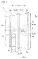
- FIG. 1 is a side view of a gas turbine in an embodiment according to the present invention.
- FIG. 2 is a side view of a main portion of the gas turbine in the embodiment according to the present invention.
- FIG. 3 is a perspective view of an auxiliary member for assembly/disassembly and a gas turbine casing around the auxiliary member in the embodiment according to the present invention.
- FIG. 4 is a side view of the auxiliary member for assembly/disassembly and the gas turbine casing around the auxiliary member in the embodiment according to the present invention.
- FIG. 5 is a plan view of the auxiliary member for assembly/disassembly and the gas turbine casing around the auxiliary member in the embodiment according to the present invention.
- FIG. 6 is a flowchart showing a disassembly procedure of the gas turbine casing in the embodiment according to the present invention.
- FIG. 7 is a plan view of the auxiliary member for assembly/disassembly and the gas turbine casing around the auxiliary member in a disassembly process of the embodiment according to the present invention.
- FIG. 8 is a side view of the auxiliary member for assembly/disassembly and the gas turbine casing around the auxiliary member in the disassembly process of the embodiment according to the present invention.
- FIG. 9 is a flowchart showing an assembly procedure of the gas turbine casing in the embodiment according to the present invention.
- FIG. 10 is a plan view of the auxiliary member for assembly/disassembly and the exhaust casing around the auxiliary member in an assembly process of the embodiment according to the present invention.
- FIG. 11 is an explanatory view (first) showing the auxiliary member for assembly/disassembly and the exhaust casing when viewed from an axial direction in the assembly process of the embodiment according to the present invention.
- FIG. 12 is an explanatory view (second) showing the auxiliary member for assembly/disassembly and the exhaust easing when viewed from an axial direction in the assembly process of the embodiment according to the present invention.
- FIG. 13 is an explanatory view (third) showing the auxiliary member for assembly/disassembly and the exhaust casing when viewed from an axial direction in the assembly process of the embodiment according to the present invention.
- FIG. 14 is a perspective view of an auxiliary member for assembly/disassembly and a gas turbine casing around the auxiliary member in a modification example of the embodiment according to the present invention.
- a gas turbine of the present embodiment includes a compressor 1 , a plurality of combustors 4 , and a turbine 2 .
- the compressor 1 compresses outside air and generates compressed air.
- the combustor 4 mixes a fuel from a fuel supply source with the compressed air, combusts the mixture, and generates combustion gas.
- the turbine 2 is driven by the combustion gas.
- the compressor 1 includes a compressor rotor 5 and a compressor casing 10 .
- the compressor rotor 5 is rotated about a rotational axis Ar which extends in a horizontal direction.
- the compressor casing 10 covers the outer circumference of the compressor rotor 5 .
- the turbine 2 includes a turbine rotor 6 , a turbine casing 20 , and an exhaust casing 30 .
- the turbine rotor 6 is connected to the compressor rotor 5 and is rotated around the above-described rotational axis Ar.
- the turbine casing 20 covers the outer circumference of the turbine rotor 6 .
- the combustion gas which drives the turbine rotor 6 passes through the exhaust casing 30 as exhaust gas.
- the turbine casing 20 is connected to the downstream side of the compressor casing 10
- the exhaust casing 30 is connected to the downstream side of the turbine casing 20
- a plurality of combustors 4 are connected to a portion of the upstream side in the turbine casing 20
- the gas turbine casing 9 includes the compressor casing 10 , the turbine casing 20 , and the exhaust casing 30 .
- the direction in which the rotational axis Ar extends is referred to as an axial direction Da
- the direction around the rotational axis is referred to as a circumferential direction Dc.
- Longitudinal flange portions (axial flange portions) 12 , 22 , and 32 which protrude toward the outer side in a radial direction Dr having the rotational axis Ar as the center along the entire circumference of each of the tube portions 11 , 21 , and 31 , are formed in a downstream end portion of the tube portion 11 of the compressor casing 10 , upstream and downstream end portions of the tube portion 21 of the turbine casing 20 , and an upstream end portion of the tube portion 31 of the exhaust casing 30 .
- the longitudinal flange portion 12 of the downstream end portion of the compressor casing 10 is connected to the longitudinal flange portion 22 of the upstream side end portion of the turbine casing 20 through a bolt and a nut which are used as a fastener.
- the longitudinal flange portion 22 of the downstream side end portion of the turbine casing 20 is connected to the longitudinal flange portion 32 of the upstream side end portion of the exhaust casing 30 through a bolt and a nut (first fastener) which are used as a fastener.
- the compressor casing 10 , the turbine casing 20 , and the exhaust casing 30 include lower half casings (first easing members) 10 a , 20 a , and 30 a , and upper half casings (second casing members) 10 b , 20 b , and 30 b .
- the lower half casings 10 a , 20 a , and 30 a are portions in the circumferential direction Dc and form the lower side of each of the casings 10 , 20 , and 30 .
- the upper half casings 10 b , 20 b , and 30 b are the other portions in the circumferential direction Dc and form the upper side of each of the casings 10 , 20 , and 30 .
- the lower half casing 10 a and the upper half casing 10 b of the compressor casing 10 include half tube portions 11 a and 11 b , axial half flange portions 12 a and 12 b , and horizontal flange portions (circumferential flange portions) 13 a and 13 b ,
- the half tube portions 11 a and 11 b form the halves of the lube portion 11 of the compressor casing 10 .
- the axial half flange portions 12 a and 12 b form the halves in the circumferential direction Dc of the longitudinal flange portion 12 .
- the horizontal flange portions 13 a and 13 b are formed on both ends in the circumferential direction Dc of the half tube portions 11 a and 11 b and are formed so as to protrude toward the outer side in the radial direction Dr from the half tube portions 11 a and 11 b.
- the lower half casing 20 a and the upper half casing 20 b of the turbine casing 20 also include half tube portions 21 a and 21 b , axial half flange portions 22 a and 22 b , and horizontal flange portions 23 a and 23 b .
- the lower half casing 30 a and the upper half casing 30 b of the exhaust casing 30 also include half tube portions 31 a and 31 b , axial half flange portions 32 a and 32 b , and horizontal flange portions 33 a and 33 b.
- the horizontal flange portions 13 a , 23 a , and 33 a of the lower half casings 10 a , 20 a , and 30 a and the horizontal flange portions 13 b , 23 b , and 33 b of the upper half casings 10 b , 20 b , and 30 b of each of the casings 10 , 20 , and 30 face each other and are connected to each other by a bolt and a nut which are a fastener.
- the bolt and the nut which connect the lower half casing 10 a and the upper half casing 10 b of the compressor casing 10 , the bolt and the nut (second fastener) which connect the lower half casing 20 a and the upper half casing 20 b of the turbine casing 20 , and the bolt and the nut (third fastener) which connect the lower half casing 30 a and the upper half casing 30 b of the exhaust casing 30 may have the same sizes as one another or may have different sizes from one another.
- the gas turbine of the present embodiment includes an auxiliary member set for assembly/disassembly for easily performing the assembly and disassembly of the gas turbine casing 9 .
- the auxiliary member set for assembly/disassembly includes four auxiliary members for assembly/disassembly 40 which are the same as one another.
- the auxiliary member for assembly/disassembly 40 includes a fixing portion 41 and a jack receiving portion 45 .
- the fixing portion 41 is fixed to one half casing 30 a (or 30 b ) of the lower half casing 30 a and the upper half casing 30 b of the exhaust casing 30 .
- the jack receiving portion 45 extends from the fixing portion 41 and faces the outer surface of the other half casing 30 b (or 30 a ).
- the fixing portion 41 is formed in a rectangular parallelepiped shape, and one surface of the rectangular parallelepiped forms a fixed surface 42 which contacts the outer surface of the horizontal flange portion 33 a (or 33 b ) of one half casing 30 a (or 30 b ).
- a plurality of bolt holes 41 v which penetrate from a fixed opposite surface 42 x paired with the fixed surface 42 to the fixed surface 42 are formed in the fixing portion 41 .
- first axial receiving surface 43 one surface adjacent to the fixed surface 42 is referred to as a first axial receiving surface 43
- a surface paired with the first axial receiving surface 43 is referred to as a receiving opposite surface 43 x
- a pair of surfaces which is adjacent to the fixed surface 42 and the first axial receiving surface 43 and faces toward the circumferential direction Do is referred to as circumferential surfaces 44 .
- the jack receiving portion 45 includes a radial receiving portion 46 and an axial receiving portion 48 .
- the radial receiving portion 46 extends in a direction perpendicular to one circumferential surface 44 of the fixing portion 41 and is funned along the fixed opposite surface 42 x.
- the axial receiving portion 48 extends in the direction perpendicular to the circumferential surface 44 and is formed along the receiving opposite surface 43 x.
- the jack receiving portion 45 is formed in an L shape, one of the vertical line and horizontal line of the L shape forms the radial receiving portion 46 , and the other forms the axial receiving portion 48 .
- a surface of the fixed surface 42 side of the fixing portion 41 forms a radial receiving surface 47 parallel to the fixed surface 42 .
- a surface of the first axial receiving surface 43 side of the fixing portion 41 forms a second axial receiving surface 49 parallel to the first axial receiving surface 43 .
- the above-described four auxiliary members for assembly/disassembly 40 are fixed to the exhaust casing 30 in advance.
- two auxiliary members for assembly/disassembly 40 of four auxiliary members for assembly/disassembly 40 are set as first auxiliary members for assembly/disassembly 40 a and are fixed to the pair of horizontal flange portions 33 a in the lower half casing 30 a of the exhaust casing 30 .
- first auxiliary member for assembly/disassembly 40 a of two first auxiliary members for assembly/disassembly 40 a the fixed surface 42 contacts the radial end surface of the horizontal flange portion 33 a in the lower half casing 30 a , and the radial receiving surface 47 faces the radial end surface of the horizontal flange portion 33 b in the upper half casing 30 b .
- the first auxiliary member for assembly/disassembly 40 a is fixed to the horizontal flange portion 33 a of the lower half casing 30 a using bolts 50 ( FIG. 5 ) which are inserted into the bolt holes 41 v of the fixing portion 41 .
- first auxiliary member for assembly/disassembly 40 a is fixed to the horizontal flange portion 33 a of the opposite side in the radial direction in the lower half casing 30 a .
- Two remaining auxiliary members for assembly/disassembly 40 of four auxiliary members for assembly/disassembly 40 are set as second auxiliary members for assembly/disassembly 40 b and are fixed to the pair of horizontal flange portions 33 b in the upper half casing 30 b of the exhaust casing 30 .
- the fixed surface 42 contacts the radial end surface of the horizontal flange portion 33 b in the upper half casing 30 b
- the radial receiving surface 47 faces the radial end surface of the horizontal flange portion 33 a in the lower half casing 30 a
- the first axial receiving surface 43 faces the second axial receiving surface 49 of the first auxiliary member for assembly/disassembly 40 a .
- the second auxiliary member for assembly/disassembly 40 b is fixed to the horizontal flange portion 33 b of the upper half casing 30 b using bolts 50 which are inserted into the bolt holes 41 v of the fixing portion 41 . Similar to the above-described second auxiliary member for assembly/disassembly 40 b , one remaining second auxiliary member for assembly/disassembly 40 b is fixed to the horizontal flange portion 33 b of the opposite side in the radial direction in the upper half casing 30 b.
- the gas turbine casing 9 is deformed due to its own weight, secular deformation due to use for a long time, or the like, and as shown by a thick broken line L in FIG. 1 , the center portion in the axial direction Da of the gas turbine casing 9 is lowered, and both end portions in the axial direction Da of the gas turbine casing 9 are lifted.
- an interval in the axial direction Da between the upper end of the upper half casing 10 b of the compressor casing 10 and the upper end of the upper half casing 30 b of the exhaust casing 30 is narrowed with respect to an interval in the axial direction Da between the lower end of the upper half casing 10 b of the compressor casing 10 and the lower end of the upper half casing 30 b of the exhaust casing 30 which are disposed on the end side in the axial direction Da.
- the above-described plurality of auxiliary members for assembly/disassembly 40 is prepared (S 1 ).
- the plurality of auxiliary members for assembly/disassembly 40 is fixed to the exhaust casing 30 (S 2 ).
- the first auxiliary member for assembly/disassembly (first axial auxiliary member) 40 a of the plurality of auxiliary members for assembly/disassembly 40 is fixed to the lower half casing (first casing member) 30 a of the exhaust casing 30 using the bolts 50 ( FIG. 5 ).
- the second auxiliary member for assembly/disassembly (second axial auxiliary member) 40 b is fixed to the upper half casing (second casing member) 30 b using bolts 50 with an interval in the axial direction Da to the first auxiliary member for assembly/disassembly 40 a . If each of the auxiliary members for assembly/disassembly 40 a and 40 b is fixed, the first axial receiving surface 43 of the first auxiliary member for assembly/disassembly 40 a and the second axial receiving surface 49 of the second auxiliary member for assembly/disassembly 40 b are perpendicular to each other in the axial direction Da and face each other.
- the second axial receiving surface 49 of the first auxiliary member for assembly/disassembly 40 a and the first axial receiving surface 43 of the second auxiliary member for assembly/disassembly 40 b are perpendicular to each other in the axial direction Da and face each other.
- the plurality of auxiliary members for assembly/disassembly 40 are prepared in the manufacturing process of the gas turbine, and the plurality of auxiliary members for assembly/disassembly 40 are fixed to the exhaust casing 30 . Therefore, the preparation step (S 1 ) and the fixation step (S 2 ) of the auxiliary member for assembly/disassembly 40 are included in the manufacturing process of the gas turbine.
- the bolts and the nuts which connect the lower half casing 10 a and the upper half casing 10 b of the compressor casing 10 are removed.
- the bolts and the nuts which connect the lower half casing 20 a and the upper half casing 20 b of the turbine casing 20 are removed.
- the bolts and the nuts which connect the lower half casing 30 a and the upper half casing 30 b of the exhaust casing 30 are removed.
- the bolts and the nuts which connect the upper half casing 10 b of the compressor casing 10 and the upper half casing 20 b of the turbine casing 20 are removed.
- the bolts and the nuts which connect the upper half easing 20 b of the turbine casing 20 and the upper half casing 30 b of the exhaust casing 30 are removed (S 3 ).
- the order in which the bolts and the nuts are removed is not limited to the above-described order.
- a jack 60 is disposed between the second axial receiving surface 49 of the first auxiliary member for assembly/disassembly 40 a which is fixed to the lower half casing 30 a of the exhaust casing 30 and the first axial receiving surface 43 of the second auxiliary member for assembly/disassembly 40 b which is fixed to the upper half casing 30 b of the exhaust casing 30 (S 4 ).
- a head surface 61 of the jack 60 contacts one receiving surface 43 (or 49 ) of the second axial receiving surface 49 of the first auxiliary member for assembly/disassembly 40 a and the first axial receiving surface 43 of the second auxiliary member for assembly/disassembly 40 b , and a base surface 62 of the jack 60 contacts the other receiving surface 49 (or 43 ).
- the jack 60 used at this time may be a mechanical jack which uses a screw or the like, or may be a hydraulic jack, and in the present embodiment, the drive form of the jack does not matter.
- the jack 60 is disposed between the second axial receiving surface 49 of the first auxiliary member for assembly/disassembly 40 a and the first axial receiving surface 43 of the second auxiliary member for assembly/disassembly 40 b .
- the jack 60 may be disposed between the first axial receiving surface 43 of the first auxiliary member for assembly/disassembly 40 a and the second axial receiving surface 49 of the second auxiliary member for assembly/disassembly 40 b .
- the jacks 60 and 60 are disposed between the first auxiliary members for assembly/disassembly 40 a and 40 a which are fixed to each of the pair of horizontal flange portions 33 a and 33 a of the lower half casing 30 a and the second auxiliary members for assembly/disassembly 40 b and 40 b which are fixed to each of the pair of horizontal flange portions 33 b and 33 b of the upper half casing 30 b .
- the jack 60 may be disposed only between the first auxiliary member for assembly/disassembly 40 a which is fixed to one of the pair of horizontal flange portions 33 a of the lower half easing 30 a and the second auxiliary member for assembly/disassembly 40 b which is fixed to one of the pair of horizontal flange portions 33 b of the upper half casing 30 b.
- the plurality of auxiliary members for assembly/disassembly 40 is fixed to the exhaust casing 30 in advance.
- the plurality of auxiliary members for assembly/disassembly 40 are not fixed to the exhaust casing 30 in advance, it is necessary to perform the auxiliary member preparation step (S 1 ) and the auxiliary member fixation step (S 2 ) before the jack disposition step (S 4 ) at the latest.
- the interval between the head surface 61 and the base surface 62 of the jack 60 which faces toward the axial direction Da of the gas turbine casing 9 is widened by operating the jack 60 (S 5 ).
- the upper half casing 30 b and the lower half casing 30 a of the exhaust casing 30 move to directions which are opposite to each other in the axial direction Da.
- the upper half casing 20 b of the turbine casing 20 is positioned on the upstream side of the upper half casing 30 b of the exhaust casing 30 .
- the upper half casing 30 b of the exhaust casing 30 moves in the direction away from the upper half casing 20 b of the turbine casing 20 in the axial direction Da, that is, to the downstream side, and is separated from the upper half casing 20 b of the turbine casing 20 .
- the plurality of auxiliary members for assembly/disassembly 40 which are prepared in Step 1 and are fixed in Step 2 are used for moving the upper half casing 30 b of the exhaust casing 30 in the axial direction Da at the time of disassembly, the auxiliary members for assembly/disassembly function as the axial auxiliary member.
- the upper half casing 20 b of the turbine casing 20 is lifted using a crane or the like, and the upper half casing 20 b is removed from the lower half casing 20 a (S 6 ).
- the upper half casing 30 b of the exhaust casing 30 moves to the downstream side, and since the interval in the axial direction Da between the upper half casing 10 b of the compressor casing 10 and the upper half casing 30 b of the exhaust casing 30 is widened, the flange or the like of the upper half casing 20 b of the turbine casing 20 is not damaged, and the upper half casing 20 b can be easily removed.
- the upper half casing 30 b of the exhaust casing 30 and the upper half casing 10 b of the compressor casing 10 are sequentially lifted using a crane or the like, and the upper half casings 30 b and 10 b are removed (S 7 and S 8 ). In this way, the disassembly operation of the gas turbine casing 9 finishes.
- the upper half casing 30 b of the exhaust casing 30 is removed after the upper half casing 20 b of the turbine casing 20 is removed.
- the upper half casing 20 b of the turbine casing 20 may be removed after the upper half casing 30 b of the exhaust casing 30 is removed.
- an interval in the radial direction (horizontal direction) Dr between both end portions in the circumferential direction Dc of the upper half easing 30 b may be widened or narrowed with respect to an interval in the radial direction (horizontal direction) Dr between both end portions in the circumferential direction Do of the lower half casing 30 a due to effects of heat Particularly, the deformation tendency is high in the exhaust casing 30 which is subjected to a high temperature gas.
- the above-described plurality of auxiliary members for assembly/disassembly 40 is prepared (S 11 ).
- the plurality of auxiliary members for assembly/disassembly 40 is fixed to the exhaust casing 30 (S 12 ).
- the fixing, portion 41 of the auxiliary member for assembly/disassembly 40 ( 40 a ) is fixed to one half casing 30 a (or 30 b ), in which the interval in the radial direction (horizontal direction) Dr between both ends in the circumferential direction Dc is narrowed, of the lower half casing (first casing member) 30 a and the upper half casing (second casing member) 30 b of the exhaust casing 30 .
- each auxiliary member for assembly/disassembly 40 If the fixing portion 41 of each auxiliary member for assembly/disassembly 40 is fixed to the one half casing 30 a (or 30 b ), the radial receiving surface 47 of each auxiliary member for assembly/disassembly 40 becomes the surface perpendicular to the radial direction Dr of the exhaust casing 30 .
- the interval of the lower half casing 30 a is narrower than that of the upper half casing 30 b , and the auxiliary member for assembly/disassembly 40 is fixed to the lower half casing 30 a .
- the plurality of auxiliary members for assembly/disassembly 40 ( 40 a and 40 b ) are prepared in the manufacturing process of the gas turbine and the plurality of auxiliary members for assembly/disassembly 40 are fixed to the exhaust casing 30 in advance, similar to the preparation step (S 1 ) and the fixation step (S 2 ) of the auxiliary member for assembly/disassembly 40 ( 40 a and 40 b ) at the time of disassembly, the preparation step (S 11 ) and the fixation step (S 12 ) of the auxiliary member for assembly/disassembly 40 at the time of assembly are also included in the manufacturing process of the gas turbine.
- the upper half casing 30 b is placed on the lower half casing 30 a so that the inner surface of the lower half casing 30 a and the inner surface of the upper half casing 30 b of the exhaust casing 30 face each other (S 13 ).
- the jack 60 is disposed between the radial receiving surface 47 of the auxiliary member for assembly/disassembly 40 ( 40 a and 40 b ) which is fixed to the lower half casing 30 a and the end surface 33 c in the radial direction Dr in the horizontal flange portion 33 a of the upper half casing 30 b (S 14 ).
- the plurality of auxiliary members for assembly/disassembly 40 ( 40 a and 40 b ) are fixed to the exhaust casing 30 in advance.
- the plurality of auxiliary members for assembly/disassembly 40 ( 40 a and 40 b ) are not fixed to the exhaust casing 30 in advance, it is necessary to perform the auxiliary member preparation step (S 11 ) and the auxiliary member fixation step (S 12 ) before the jack disposition step (S 14 ) at the latest.
- the interval between the head surface and the base surface of the jack 60 which faces toward the radial direction Dr of the gas turbine casing 9 is widened by operating the jack 60 (S 15 ). Due to this operation, in the upper half casing 30 b of the exhaust casing 30 , the interval in the radial direction Dr between both end portions in the circumferential direction Dc is narrowed.
- the auxiliary members for assembly/disassembly 40 which are prepared in Step 11 and are fixed in Step 12 are used for correction of the deformation in the radial direction Dr of the lower half casing 30 a or the upper half casing 30 b at the time of assembly, the auxiliary members for assembly/disassembly function as the radial auxiliary members.
- the exhaust casing 30 is deformed due to heat, and thus, the interval in the radial direction (horizontal direction) Dr between both end portions in the circumferential direction Dc of the upper half casing 30 b may be widened with respect to the interval in the radial direction (horizontal direction) Dr between both end portions in the circumferential direction Dc of the lower half casing 30 a .
- the upper half casing 30 b can be easily connected to the lower half casing 30 a.
- the auxiliary member for assembly/disassembly 40 ( 40 b ) is fixed to the upper half casing 30 b in which the interval in the radial direction Dr between both end portions in the circumferential direction Dc is narrower than the lower half casing 30 a (S 12 ).
- the jack 60 is disposed between the radial receiving surface 47 of the auxiliary member for assembly/disassembly 40 which is fixed to the upper half casing 30 b and the end surface in the radial direction Dr in the horizontal flange portion 33 a of the lower half casing 30 a (S 14 ), and the jack 60 is operated (S 15 ).
- the interval in the radial direction Dr between both end portions in the circumferential direction Dc of the lower half casing 30 a is narrowed.
- the auxiliary members for assembly/disassembly 40 ( 40 a and 40 b ) and 40 ( 40 a and 40 b ) are fixed to each of the pair of horizontal flange portions 33 a and 33 a of the lower half casing 30 a , and the jacks 60 and 60 are disposed between the upper half casing 30 b and each of the auxiliary members for assembly/disassembly 40 ( 40 a and 40 b ) and 40 ( 40 a and 40 b ).
- the auxiliary members for assembly/disassembly 40 may be fixed to only one of the pair of horizontal flange portions 33 a of the lower half casing 30 a , and the jack 60 may be disposed between the upper half casing 30 b and the one auxiliary member for assembly/disassembly 40 ( 40 a and 40 b ).
- the jack 60 is operated after temporary connection or connection of the other horizontal flange portion 33 a of the upper half casing 30 b and the other horizontal flange portion 33 b of the lower half casing 30 a is preformed using the bolts and the nuts 51 , one jack 60 is operated.
- the present invention can be also similarly applied to a case where the turbine casing 20 or the compressor casing 10 is deformed due to heat.
- the example of the gas turbine in which the rotor extends in the horizontal direction is described.
- the similar operation is performed on the first casing member which forms a portion in the circumferential direction Dc of the casing and the second casing member which forms the other portion in the circumferential direction Dc, and the present invention can cope with the deformation of the casing.
- an auxiliary member for assembly/disassembly 70 of the present modification example includes a fixing portion 71 , and a jack receiving portion 75 which extends from the fixing portion 71 and faces the outer surface of the other half casing 30 b (or 30 a ).
- the fixing portion 71 is fixed to one half casing 30 a (or 30 b ) of the upper half casing 30 b and the lower half casing 30 a .
- the jack receiving portion 75 extends from the fixing portion 71 and faces the outer surface of the other half casing 30 b (or 30 a ).
- the fixing portion 71 is formed in a rectangular parallelepiped shape, and one surface of the rectangular parallelepiped forms a fixed surface 72 which contacts the outer surface of the horizontal flange portion 33 a (or 33 b ) of one half casing 30 a (or 30 b ).
- a surface paired with the fixed surface 72 is referred to as a fixed opposite surface 72 x
- a pair of surfaces adjacent to the fixed surface 72 is referred to as first axial receiving surfaces 73
- a pair of surfaces which is adjacent to the fixed surface 72 and the first axial receiving surface 73 and faces the circumferential direction Dc is referred to as circumferential surfaces 74 .
- Bolt holes 80 are formed on the fixing portion 71 .
- the jack receiving portion 75 is formed in a rectangular parallelepiped shape and is formed along the fixed opposite surface 72 x on one circumferential surface 74 of the fixing portion 71 .
- the surface parallel to the fixed surface 72 in the surface of the fixed surface 72 side of the fixing portion 71 forms a radial receiving surface 77 .
- the surface parallel to the first axial receiving surface 73 of the fixing portion 71 forms a second axial receiving surface 79 .
- the jack 60 is disposed between the radial receiving surface 77 of the auxiliary member for assembly/disassembly 70 and the horizontal flange portion 33 b (or 33 a ) of the half casing 30 b ( 30 a ) to which the auxiliary member for assembly/disassembly 70 is not fixed.
- the jack 60 is disposed between the first axial receiving surface 73 of one auxiliary member for assembly/disassembly 70 a and the second axial receiving surface 79 of the other auxiliary member for assembly/disassembly 70 b of two auxiliary members for assembly/disassembly 70 a and 70 b which are disposed with an interval between each other in the axial direction Da.
- the auxiliary member for assembly/disassembly 70 since bolt holes are not present in the fixing portion 71 and the jack receiving portion 75 is a rectangular parallelepiped shape, although the auxiliary member has a significantly simple shape, if the auxiliary member includes the fixing portion 71 which is fixed to one half casing 30 a (or 30 b ) of the upper half casing 30 b and the lower half casing 30 a and the jack receiving portion 75 which extends from the fixing portion 71 and faces the outer surface of the other half casing 30 b (or 30 a ), the function can be achieved.
- the auxiliary members for assembly/disassembly 40 and 70 are fixed as the radial auxiliary member, it is preferable that the radial receiving surfaces 47 and 77 of the auxiliary members for assembly/disassembly 40 and 70 be perpendicular to the radial direction Dr of the casing. The reason is that stability of the jack 60 is increased. However, the radial receiving surfaces do not need to be perpendicular to the radial direction Dr of the casing.
- the auxiliary members for assembly/disassembly 40 and 70 are fixed as the axial auxiliary member, it is preferable that the axial receiving surfaces 43 , 49 , 73 , and 79 of the auxiliary members for assembly/disassembly 40 and 70 be perpendicular to the axial direction Da of the casing. The reason is that stability of the jack 60 is increased. However, the axial receiving surfaces do not need to be perpendicular to the axial direction Da of the casing.
Landscapes
- Engineering & Computer Science (AREA)
- Mechanical Engineering (AREA)
- General Engineering & Computer Science (AREA)
- Supercharger (AREA)
- Turbine Rotor Nozzle Sealing (AREA)
Abstract
Description
- [Patent Document 1] Japanese Unexamined Patent Application, First Publication No. 2008-64043
-
- 1: compressor, 2: turbine, 4: combustor. 5: compressor rotor, 6: turbine rotor, 9: gas turbine casing, 10: compressor casing, 10 a, 20 a, 30 a: lower half casing (first casing member), 10 b, 20 b, 30 b: upper half casing (second casing member), 12 a, 12 b, 22 a, 22 b, 32 a. 32 b: axial half flange portion, 13 a, 13 b, 23 a, 23 b, 33 a, 33 b: horizontal flange portion, 40, 70: auxiliary member for assembly/disassembly, 40 a: first auxiliary member for assembly/disassembly, 40 b: second auxiliary member for assembly/disassembly, 41, 71: fixing portion, 42, 72: fixed surface, 43, 73: first axial receiving surface, 45, 75: jack receiving portion, 47, 77: radial receiving surface, 49, 79: second axial receiving surface, 60: jack
Claims (13)
Applications Claiming Priority (2)
| Application Number | Priority Date | Filing Date | Title |
|---|---|---|---|
| JP2012-047222 | 2012-03-02 | ||
| JP2012047222A JP5881474B2 (en) | 2012-03-02 | 2012-03-02 | Assembly / disassembly jig for gas turbine casing, gas turbine provided with the same, assembly method and disassembly method for gas turbine casing |
Publications (2)
| Publication Number | Publication Date |
|---|---|
| US20130230392A1 US20130230392A1 (en) | 2013-09-05 |
| US9539680B2 true US9539680B2 (en) | 2017-01-10 |
Family
ID=49042935
Family Applications (1)
| Application Number | Title | Priority Date | Filing Date |
|---|---|---|---|
| US13/663,576 Active 2035-11-12 US9539680B2 (en) | 2012-03-02 | 2012-10-30 | Auxiliary member for assembly/disassembly of gas turbine casing, gas turbine having the same, assembly method of gas turbine casing, and disassembly method of gas turbine casing |
Country Status (6)
| Country | Link |
|---|---|
| US (1) | US9539680B2 (en) |
| JP (1) | JP5881474B2 (en) |
| KR (1) | KR101555798B1 (en) |
| CN (1) | CN104136743B (en) |
| DE (1) | DE112012005971B4 (en) |
| WO (1) | WO2013128712A1 (en) |
Cited By (3)
| Publication number | Priority date | Publication date | Assignee | Title |
|---|---|---|---|---|
| US10428737B2 (en) | 2015-04-27 | 2019-10-01 | Ansaldo Energia Switzerland AG | Gas turbine disassembly method |
| IT202300006339A1 (en) * | 2023-03-31 | 2023-07-01 | Nuovo Pignone Tecnologie Srl | AN EXPANDER FOR OXY-COMBUSTION CYCLES AND SIMILAR |
| US20250332670A1 (en) * | 2024-04-30 | 2025-10-30 | Ge Vernova Infrastructure Technology Llc | Separation tool and method for nozzle segments of gas turbines |
Families Citing this family (12)
| Publication number | Priority date | Publication date | Assignee | Title |
|---|---|---|---|---|
| US9441498B2 (en) * | 2013-10-30 | 2016-09-13 | Siemens Energy, Inc. | Process and tool for aligning a seal housing assembly with a casing of a gas turbine engine |
| JP5869051B2 (en) | 2014-06-09 | 2016-02-24 | 三菱日立パワーシステムズ株式会社 | Rotating machine, rotating machine assembly method, rotating machine maintenance method |
| PL3284919T3 (en) * | 2016-08-16 | 2024-12-09 | General Electric Technology Gmbh | Axial flow turbine having a diaphragm split in two halves at a joint plane |
| GB2559412B (en) * | 2017-02-06 | 2019-05-15 | Ford Global Tech Llc | Heatshield for a band clamp |
| WO2020036120A1 (en) * | 2018-08-17 | 2020-02-20 | 三菱日立パワーシステムズ株式会社 | Position adjustment method and position adjustment jig for arc-shaped member |
| KR200493032Y1 (en) * | 2019-08-21 | 2021-01-20 | 주식회사 한국가스기술공사 | Disassembling jig for gas measuring equipment |
| JP7411458B2 (en) * | 2020-03-11 | 2024-01-11 | 三菱重工業株式会社 | Combustion tube installation method and combustion tube installation jig |
| CN111266861B (en) * | 2020-03-31 | 2021-04-20 | 中国航发动力股份有限公司 | Assembly fixture of low-pressure turbine of engine |
| JP7222956B2 (en) * | 2020-08-25 | 2023-02-15 | 三菱重工業株式会社 | Steam turbine casing assembly and disassembly method |
| US11873727B2 (en) | 2021-04-15 | 2024-01-16 | General Electric Company | System and method for hoisting gas engine assemblies |
| JP7299945B2 (en) | 2021-06-04 | 2023-06-28 | 三菱重工業株式会社 | Turbine casing, gas turbine and alignment method |
| JP6961856B1 (en) | 2021-06-16 | 2021-11-05 | 三菱パワー株式会社 | Turbine assembly and how to assemble the turbine assembly |
Citations (29)
| Publication number | Priority date | Publication date | Assignee | Title |
|---|---|---|---|---|
| US1707870A (en) * | 1928-04-30 | 1929-04-02 | Frank M Morton | Roll-spreading jack |
| US1957699A (en) * | 1930-04-25 | 1934-05-08 | Allis Chalmers Mfg Co | Flange connection |
| US2393795A (en) * | 1944-09-08 | 1946-01-29 | Herbert L Miller | Flange spreader |
| US3107419A (en) * | 1959-07-13 | 1963-10-22 | Connard G Sandlfer | Flange spreader |
| US3628884A (en) * | 1970-06-26 | 1971-12-21 | Westinghouse Electric Corp | Method and apparatus for supporting an inner casing structure |
| US3741680A (en) * | 1972-04-05 | 1973-06-26 | Avco Corp | Split housing piloting device |
| US3764226A (en) * | 1972-04-05 | 1973-10-09 | Avco Corp | Piloting device for split housings having different thermal coefficients of expansion |
| US3869784A (en) * | 1973-10-03 | 1975-03-11 | Richard R Simpson | Tool for aligning articles |
| US4015324A (en) * | 1975-05-23 | 1977-04-05 | Arnold Lutter | Device for separating flange pipes |
| US4513955A (en) * | 1983-01-24 | 1985-04-30 | Daubon Charles E | Level clamp apparatus |
| US4540199A (en) * | 1982-09-01 | 1985-09-10 | Neill David C | Jack bolt assembly |
| US5129136A (en) * | 1991-03-22 | 1992-07-14 | Richardson H Gary | Flange spreader |
| US5228181A (en) * | 1991-08-26 | 1993-07-20 | Ingle Michael D | Flange aligning device |
| US5560091A (en) * | 1994-05-26 | 1996-10-01 | Labit, Jr.; Sexon J. | Apparatus for aligning pipe flanges |
| US5605438A (en) * | 1995-12-29 | 1997-02-25 | General Electric Co. | Casing distortion control for rotating machinery |
| US6267556B1 (en) | 1998-04-21 | 2001-07-31 | Kabushiki Kaisha Toshiba | Steam turbine |
| US6298534B1 (en) * | 1997-11-21 | 2001-10-09 | Applied Materials, Inc. | Chamber component removal system, apparatus and method |
| US6352404B1 (en) | 2000-02-18 | 2002-03-05 | General Electric Company | Thermal control passages for horizontal split-line flanges of gas turbine engine casings |
| US20030180140A1 (en) * | 2002-03-20 | 2003-09-25 | Martin Reigl | Flange bolt for turbines |
| US20050044685A1 (en) | 2003-08-28 | 2005-03-03 | Brooks Robert T. | Tooling provision for split cases |
| US6983525B2 (en) * | 2003-01-07 | 2006-01-10 | Valtra, Inc. | Alignment clamp |
| US20060034678A1 (en) | 2004-08-10 | 2006-02-16 | General Electric Company | Turbine shell jacking pockets |
| JP2008064043A (en) | 2006-09-08 | 2008-03-21 | Toshiba Corp | Gas turbine equipment, installation apparatus and installation method |
| US20100226770A1 (en) * | 2009-03-06 | 2010-09-09 | General Electric Company | Alignment device for gas turbine casings |
| CN102325980A (en) | 2008-12-23 | 2012-01-18 | 索拉透平公司 | Gas turbine engine and system for servicing gas turbine engine |
| US20120039709A1 (en) * | 2010-07-13 | 2012-02-16 | Alstom Technology Ltd | Method and device for adjusting the rotor position in a gas turbine or steam turbine |
| US20120272496A1 (en) * | 2011-04-29 | 2012-11-01 | General Electric Company | System and method for lifting a casing section |
| US8602390B2 (en) * | 2010-11-30 | 2013-12-10 | General Electric Company | Jacking mechanism |
| US9115828B2 (en) * | 2012-10-15 | 2015-08-25 | Rodney S. Nakamura | Transverse pipe flange separator |
-
2012
- 2012-03-02 JP JP2012047222A patent/JP5881474B2/en active Active
- 2012-10-30 CN CN201280070649.XA patent/CN104136743B/en active Active
- 2012-10-30 KR KR1020147023737A patent/KR101555798B1/en active Active
- 2012-10-30 WO PCT/JP2012/078057 patent/WO2013128712A1/en not_active Ceased
- 2012-10-30 US US13/663,576 patent/US9539680B2/en active Active
- 2012-10-30 DE DE112012005971.9T patent/DE112012005971B4/en active Active
Patent Citations (31)
| Publication number | Priority date | Publication date | Assignee | Title |
|---|---|---|---|---|
| US1707870A (en) * | 1928-04-30 | 1929-04-02 | Frank M Morton | Roll-spreading jack |
| US1957699A (en) * | 1930-04-25 | 1934-05-08 | Allis Chalmers Mfg Co | Flange connection |
| US2393795A (en) * | 1944-09-08 | 1946-01-29 | Herbert L Miller | Flange spreader |
| US3107419A (en) * | 1959-07-13 | 1963-10-22 | Connard G Sandlfer | Flange spreader |
| US3628884A (en) * | 1970-06-26 | 1971-12-21 | Westinghouse Electric Corp | Method and apparatus for supporting an inner casing structure |
| US3764226A (en) * | 1972-04-05 | 1973-10-09 | Avco Corp | Piloting device for split housings having different thermal coefficients of expansion |
| US3741680A (en) * | 1972-04-05 | 1973-06-26 | Avco Corp | Split housing piloting device |
| US3869784A (en) * | 1973-10-03 | 1975-03-11 | Richard R Simpson | Tool for aligning articles |
| US4015324A (en) * | 1975-05-23 | 1977-04-05 | Arnold Lutter | Device for separating flange pipes |
| US4540199A (en) * | 1982-09-01 | 1985-09-10 | Neill David C | Jack bolt assembly |
| US4513955A (en) * | 1983-01-24 | 1985-04-30 | Daubon Charles E | Level clamp apparatus |
| US5129136A (en) * | 1991-03-22 | 1992-07-14 | Richardson H Gary | Flange spreader |
| US5228181A (en) * | 1991-08-26 | 1993-07-20 | Ingle Michael D | Flange aligning device |
| US5560091A (en) * | 1994-05-26 | 1996-10-01 | Labit, Jr.; Sexon J. | Apparatus for aligning pipe flanges |
| US5605438A (en) * | 1995-12-29 | 1997-02-25 | General Electric Co. | Casing distortion control for rotating machinery |
| US6298534B1 (en) * | 1997-11-21 | 2001-10-09 | Applied Materials, Inc. | Chamber component removal system, apparatus and method |
| US6267556B1 (en) | 1998-04-21 | 2001-07-31 | Kabushiki Kaisha Toshiba | Steam turbine |
| US6352404B1 (en) | 2000-02-18 | 2002-03-05 | General Electric Company | Thermal control passages for horizontal split-line flanges of gas turbine engine casings |
| US20030180140A1 (en) * | 2002-03-20 | 2003-09-25 | Martin Reigl | Flange bolt for turbines |
| US6983525B2 (en) * | 2003-01-07 | 2006-01-10 | Valtra, Inc. | Alignment clamp |
| US20050044685A1 (en) | 2003-08-28 | 2005-03-03 | Brooks Robert T. | Tooling provision for split cases |
| JP2005076633A (en) | 2003-08-28 | 2005-03-24 | United Technol Corp <Utc> | Device and method of separating two flanges |
| JP2006052733A (en) | 2004-08-10 | 2006-02-23 | General Electric Co <Ge> | Jack receiving pocket of turbine shell |
| US20060034678A1 (en) | 2004-08-10 | 2006-02-16 | General Electric Company | Turbine shell jacking pockets |
| JP2008064043A (en) | 2006-09-08 | 2008-03-21 | Toshiba Corp | Gas turbine equipment, installation apparatus and installation method |
| CN102325980A (en) | 2008-12-23 | 2012-01-18 | 索拉透平公司 | Gas turbine engine and system for servicing gas turbine engine |
| US20100226770A1 (en) * | 2009-03-06 | 2010-09-09 | General Electric Company | Alignment device for gas turbine casings |
| US20120039709A1 (en) * | 2010-07-13 | 2012-02-16 | Alstom Technology Ltd | Method and device for adjusting the rotor position in a gas turbine or steam turbine |
| US8602390B2 (en) * | 2010-11-30 | 2013-12-10 | General Electric Company | Jacking mechanism |
| US20120272496A1 (en) * | 2011-04-29 | 2012-11-01 | General Electric Company | System and method for lifting a casing section |
| US9115828B2 (en) * | 2012-10-15 | 2015-08-25 | Rodney S. Nakamura | Transverse pipe flange separator |
Non-Patent Citations (5)
| Title |
|---|
| English translation of International Search Report of PCT/JP2012/078057, date of mailing date Jan. 15, 2013. |
| First Office Action dated Sep. 6, 2015, issued in counterpart Chinese Application No. 2012-80070649.X, with English translation (11 pages). |
| International Search Report of PCT/JP2012/078057, date of mailing Jan. 15, 2013. |
| Translation of Written Opinion of the International Searching Authority (PCT/ISA/237) dated Jan. 15, 2013, issued in corresponding Application No. PCT/JP2012/078057. (4 pages). |
| Written Opinion dated Jan. 15, 2013, issued is International Application No. PCT/JP2012/078057. |
Cited By (4)
| Publication number | Priority date | Publication date | Assignee | Title |
|---|---|---|---|---|
| US10428737B2 (en) | 2015-04-27 | 2019-10-01 | Ansaldo Energia Switzerland AG | Gas turbine disassembly method |
| IT202300006339A1 (en) * | 2023-03-31 | 2023-07-01 | Nuovo Pignone Tecnologie Srl | AN EXPANDER FOR OXY-COMBUSTION CYCLES AND SIMILAR |
| WO2024199731A1 (en) * | 2023-03-31 | 2024-10-03 | Nuovo Pignone Tecnologie - S.R.L. | An expander for oxy-fuel combustion cycles and the like |
| US20250332670A1 (en) * | 2024-04-30 | 2025-10-30 | Ge Vernova Infrastructure Technology Llc | Separation tool and method for nozzle segments of gas turbines |
Also Published As
| Publication number | Publication date |
|---|---|
| KR101555798B1 (en) | 2015-09-24 |
| CN104136743B (en) | 2016-12-28 |
| KR20140114449A (en) | 2014-09-26 |
| DE112012005971B4 (en) | 2017-03-16 |
| CN104136743A (en) | 2014-11-05 |
| US20130230392A1 (en) | 2013-09-05 |
| JP5881474B2 (en) | 2016-03-09 |
| DE112012005971T5 (en) | 2014-11-13 |
| JP2013181503A (en) | 2013-09-12 |
| WO2013128712A1 (en) | 2013-09-06 |
Similar Documents
| Publication | Publication Date | Title |
|---|---|---|
| US9539680B2 (en) | Auxiliary member for assembly/disassembly of gas turbine casing, gas turbine having the same, assembly method of gas turbine casing, and disassembly method of gas turbine casing | |
| US7637110B2 (en) | Methods and apparatuses for assembling a gas turbine engine | |
| EP3061924A1 (en) | Ceramic matrix composite shroud hanger assembly | |
| CN105765175A (en) | Eccentric coupling device and method for coupling mating casings in a turbomachine | |
| US9266202B2 (en) | Rotor centralization for turbine engine assembly | |
| US8429816B2 (en) | Stator ring configuration | |
| EP3179168B1 (en) | Combustor assembly lift systems | |
| US9032599B2 (en) | Component removal apparatus for use in turbine engines and methods of removing components from turbine engines | |
| US20110164983A1 (en) | Locking Spacer Assembly | |
| EP3179170A1 (en) | Combustor assembly alignment and securement systems | |
| EP3203040B1 (en) | Lift device for turbine casing and method to lift the casing | |
| CN203847245U (en) | Balance weight and system for mounting and removing lower portions of inner shells of turbine segments of gas turbines | |
| US10429073B2 (en) | Combustor cap module and retention system therefor | |
| US20150345332A1 (en) | Horizontal joint for a rotary machine and method of assembling same | |
| US9200539B2 (en) | Turbine shell support arm | |
| EP4123128A1 (en) | Combustion can lift assembly | |
| JP2019504279A (en) | Lift trajectory for combustor assembly and turbomachine equipped with the same | |
| KR101438911B1 (en) | Equipment for testing assemblability of vane segment | |
| US10627208B2 (en) | Low resistance surface contact topography mapping |
Legal Events
| Date | Code | Title | Description |
|---|---|---|---|
| AS | Assignment |
Owner name: MITSUBISHI HEAVY INDUSTRIES, LTD., JAPAN Free format text: ASSIGNMENT OF ASSIGNORS INTEREST;ASSIGNOR:HASHIMOTO, SHINYA;REEL/FRAME:030153/0841 Effective date: 20130315 |
|
| AS | Assignment |
Owner name: MITSUBISHI HITACHI POWER SYSTEMS, LTD., JAPAN Free format text: ASSIGNMENT OF ASSIGNORS INTEREST;ASSIGNOR:MITSUBISHI HEAVY INDUSTRIES, LTD.;REEL/FRAME:034858/0078 Effective date: 20150129 |
|
| STCF | Information on status: patent grant |
Free format text: PATENTED CASE |
|
| MAFP | Maintenance fee payment |
Free format text: PAYMENT OF MAINTENANCE FEE, 4TH YEAR, LARGE ENTITY (ORIGINAL EVENT CODE: M1551); ENTITY STATUS OF PATENT OWNER: LARGE ENTITY Year of fee payment: 4 |
|
| AS | Assignment |
Owner name: MITSUBISHI POWER, LTD., JAPAN Free format text: CHANGE OF NAME;ASSIGNOR:MITSUBISHI HITACHI POWER SYSTEMS, LTD.;REEL/FRAME:054975/0438 Effective date: 20200901 |
|
| AS | Assignment |
Owner name: MITSUBISHI POWER, LTD., JAPAN Free format text: CORRECTIVE ASSIGNMENT TO CORRECT THE REMOVING PATENT APPLICATION NUMBER 11921683 PREVIOUSLY RECORDED AT REEL: 054975 FRAME: 0438. ASSIGNOR(S) HEREBY CONFIRMS THE ASSIGNMENT;ASSIGNOR:MITSUBISHI HITACHI POWER SYSTEMS, LTD.;REEL/FRAME:063787/0867 Effective date: 20200901 |