US9538841B2 - Versatile racks and related assemblies and methods - Google Patents
Versatile racks and related assemblies and methods Download PDFInfo
- Publication number
- US9538841B2 US9538841B2 US14/454,889 US201414454889A US9538841B2 US 9538841 B2 US9538841 B2 US 9538841B2 US 201414454889 A US201414454889 A US 201414454889A US 9538841 B2 US9538841 B2 US 9538841B2
- Authority
- US
- United States
- Prior art keywords
- rack
- legs
- leg
- upright position
- base
- Prior art date
- Legal status (The legal status is an assumption and is not a legal conclusion. Google has not performed a legal analysis and makes no representation as to the accuracy of the status listed.)
- Expired - Fee Related, expires
Links
Images


Classifications
-
- A—HUMAN NECESSITIES
- A47—FURNITURE; DOMESTIC ARTICLES OR APPLIANCES; COFFEE MILLS; SPICE MILLS; SUCTION CLEANERS IN GENERAL
- A47B—TABLES; DESKS; OFFICE FURNITURE; CABINETS; DRAWERS; GENERAL DETAILS OF FURNITURE
- A47B55/00—Cabinets, racks or shelf units, having essential features of rigid construction
-
- A—HUMAN NECESSITIES
- A47—FURNITURE; DOMESTIC ARTICLES OR APPLIANCES; COFFEE MILLS; SPICE MILLS; SUCTION CLEANERS IN GENERAL
- A47B—TABLES; DESKS; OFFICE FURNITURE; CABINETS; DRAWERS; GENERAL DETAILS OF FURNITURE
- A47B43/00—Cabinets, racks or shelf units, characterised by features enabling folding of the cabinet or the like
-
- A—HUMAN NECESSITIES
- A47—FURNITURE; DOMESTIC ARTICLES OR APPLIANCES; COFFEE MILLS; SPICE MILLS; SUCTION CLEANERS IN GENERAL
- A47B—TABLES; DESKS; OFFICE FURNITURE; CABINETS; DRAWERS; GENERAL DETAILS OF FURNITURE
- A47B46/00—Cabinets, racks or shelf units, having one or more surfaces adapted to be brought into position for use by extending or pivoting
-
- A—HUMAN NECESSITIES
- A47—FURNITURE; DOMESTIC ARTICLES OR APPLIANCES; COFFEE MILLS; SPICE MILLS; SUCTION CLEANERS IN GENERAL
- A47B—TABLES; DESKS; OFFICE FURNITURE; CABINETS; DRAWERS; GENERAL DETAILS OF FURNITURE
- A47B57/00—Cabinets, racks or shelf units, characterised by features for adjusting shelves or partitions
- A47B57/06—Cabinets, racks or shelf units, characterised by features for adjusting shelves or partitions with means for adjusting the height of the shelves
- A47B57/08—Cabinets, racks or shelf units, characterised by features for adjusting shelves or partitions with means for adjusting the height of the shelves consisting of grooved or notched ledges, uprights or side walls
- A47B57/10—Cabinets, racks or shelf units, characterised by features for adjusting shelves or partitions with means for adjusting the height of the shelves consisting of grooved or notched ledges, uprights or side walls the grooved or notched parts being the side walls or uprights themselves
-
- A—HUMAN NECESSITIES
- A47—FURNITURE; DOMESTIC ARTICLES OR APPLIANCES; COFFEE MILLS; SPICE MILLS; SUCTION CLEANERS IN GENERAL
- A47B—TABLES; DESKS; OFFICE FURNITURE; CABINETS; DRAWERS; GENERAL DETAILS OF FURNITURE
- A47B57/00—Cabinets, racks or shelf units, characterised by features for adjusting shelves or partitions
- A47B57/06—Cabinets, racks or shelf units, characterised by features for adjusting shelves or partitions with means for adjusting the height of the shelves
- A47B57/20—Cabinets, racks or shelf units, characterised by features for adjusting shelves or partitions with means for adjusting the height of the shelves consisting of tongues, pins or similar projecting means coacting with openings
Definitions
- racks are sold and/or shipped in an unassembled state and then assembled where the rack is to be used.
- the assembly can be complex and require tools.
- the rack may have limited versatility with regard to the configuration of the assembled rack.
- a rack that can be shipped or stored in a flat configuration and easily manipulated to an upright position for use. It is also desirable for such a rack to be sturdy in the upright position even if the rack is “assembled” without tools. It is still further desirable for the rack to be versatile not only in the movement between the flat and upright positions, but also to be adaptable to different configurations in the upright position.
- Some embodiments of the present invention are directed to a rack.
- the rack includes a base resting on a horizontal surface, a top and four elongated legs. Each leg includes a bottom portion pivotally connected to the base and a top portion pivotally connected to the top.
- the rack is movable between a flat position, with the legs are substantially parallel to the horizontal surface, and an upright position, with the legs are substantially perpendicular to the horizontal surface.
- the base and the top are substantially parallel to the horizontal surface in each of the flat and the upright positions.
- the rack includes a plurality of fasteners configured to lock the rack in the upright position.
- the plurality of fasteners may be thumb screws.
- the bottom portion of each leg may be pivotally connected to a corresponding support member of the base and the top portion of each leg may be pivotally connected to a corresponding support member of the top. In the upright position, an aperture at the bottom portion of each leg may be aligned with an aperture of the corresponding support member of the base and an aperture at the top portion of each leg may be aligned with an aperture of the corresponding support member of the top.
- one of the fasteners may be received through the aligned apertures at the bottom portion of each leg and the corresponding support member of the base and another one of the fasteners may be received through the aligned apertures at the top portion of each leg and the corresponding support member of the top.
- each leg in the upright position, includes a plurality of shelf mounting features at different vertical positions relative to the horizontal surface, with the rack further including a shelf releasably mounted between the legs and substantially parallel to the horizontal surface at a selected vertical position using the shelf mounting features.
- the plurality of shelf mounting features may include a column of spaced apart apertures in each leg.
- the shelf may include a plurality of pins with one of the pins received in one of the apertures of each leg.
- the plurality of pins may include first and second pins.
- the first pin may be operatively connected to a first button on the shelf with the first pin configured to retract into the shelf responsive to actuation of the first button.
- the second pin may be operatively connected to a second button on the shelf with the second pin configured to retract into the shelf responsive to actuation of the second button.
- each leg includes a lower leg member and an upper leg member that is movable relative to the lower leg member such that the rack is adjustable in height in the upright position.
- the upper leg member may be slidably received in the lower leg member.
- the lower leg member may include an aperture and the upper leg member may include a column of spaced apart apertures that can be selectively aligned with the aperture of the lower leg member.
- the rack may include a locking member that extends through the selectively aligned apertures to lock the rack in a selected extended position.
- the rack includes equipment mounting features on outer surfaces of two of the legs.
- the equipment mounting features may be provided in spaced apart groups of two mounting features with the two mounting features in a respective group spaced apart a distance such that 1 rack unit (1 U) equipment can be mounted thereto.
- the equipment mounting features may be provided in spaced apart groups of two mounting features such that one of the mounting features of one group and one of the mounting features of an adjacent group are spaced apart a distance such that 2 rack unit (2 U) equipment can be mounted thereto.
- the rack includes a base resting on a horizontal surface, a top and four elongated legs. Each leg includes a bottom portion pivotally connected to the base and a top portion pivotally connected to the top.
- the rack is movable between a flat position, wherein the legs are substantially parallel to the horizontal surface, and an upright position, wherein the legs are substantially perpendicular to the horizontal surface.
- the rack is lockable in the upright position.
- the rack is extendable from the upright position to a plurality of different selectable extended positions.
- the rack is lockable in the selected extended position.
- the rack includes a plurality of shelf mounting features at various selectable heights relative to the horizontal surface.
- the rack may include one or more shelves releasably mounted to the rack between the legs at one or more selected heights.
- the rack in the flat position, has a height of between about 4.5 and 6.5 inches and, in the upright position, the rack has a height of between about 22 and 24 inches. In some embodiments, in the flat position, the rack has a height of between about 4.5 and 6.5 inches and, in the upright position, the rack has a height of between about 36 and 38 inches.
- Some other embodiments of the present invention are directed to a method including providing a rack.
- the rack includes a base resting on a horizontal surface, a top and four elongated legs, with each leg including a bottom portion pivotally connected to the base and a top portion pivotally connected to the top.
- the method includes rotating the rack from a flat position, wherein the legs are substantially parallel to the horizontal surface and the base and the top are substantially parallel to the horizontal surface, to an upright position, wherein the legs are substantially perpendicular to the horizontal surface and the base and the top are substantially parallel to the horizontal surface.
- the method includes locking the rack in the upright position using a thumb screw that extends through each leg and the base and a thumb screw that extends through each leg and the top.
- Some other embodiments of the present invention are directed to a shelf configured to be releasably mounted to a rack.
- the shelf includes a shelf body, first and second fixed pins on a first side of the shelf body, first and second retractable pins on a second, opposite side of the shelf body and at least one actuator.
- the at least one actuator is operatively connected to the first and second retractable pins, and the first and second retractable pins are configured to retract into the shelf body responsive to actuation of the at least one actuator.
- FIG. 1 is an exploded perspective view of a rack according to some embodiments of the invention.
- FIG. 2 is a front perspective view of the rack of FIG. 1 in a flat position.
- FIG. 3 is a rear perspective view of the rack of FIG. 1 in the flat position.
- FIG. 4 is a front perspective view of the rack of FIG. 1 in an upright position with shelf assemblies releasably held in the rack.
- FIG. 5 is an exploded perspective view of one of the shelf assemblies of FIG. 4 .
- FIG. 6 is a front perspective view of the rack of FIG. 1 in an extended position.
- FIG. 7 is a front view of the rack of FIG. 1 in the upright position.
- FIG. 8 is a rear view of the rack of FIG. 1 in the extended position.
- FIG. 9 is a side view of the rack of FIG. 1 in the extended position.
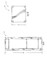
- FIG. 10 is a top view of the rack of FIG. 1 in the upright position.
- FIG. 11 is a side view of the rack of FIG. 1 in the flat position.
- spatially relative terms such as “under”, “below”, “lower”, “over”, “upper” and the like, may be used herein for ease of description to describe one element or feature's relationship to another element(s) or feature(s) as illustrated in the figures. It will be understood that the spatially relative terms are intended to encompass different orientations of the device in use or operation in addition to the orientation depicted in the figures. For example, if the device in the figures is inverted, elements described as “under” or “beneath” other elements or features would then be oriented “over” the other elements or features. Thus, the exemplary term “under” can encompass both an orientation of over and under. The device may be otherwise oriented (rotated 90 degrees or at other orientations) and the spatially relative descriptors used herein interpreted accordingly.
- any one or more aspects or features described with respect to one embodiment may be incorporated in a different embodiment although not specifically described relative thereto. That is, all embodiments and/or features of any embodiment can be combined in any way and/or combination. Applicant reserves the right to change any originally filed claim or file any new claim accordingly, including the right to be able to amend any originally filed claim to depend from and/or incorporate any feature of any other claim although not originally claimed in that manner.
- FIGS. 1-11 A rack or rack assembly 10 according to some embodiments is shown in FIGS. 1-11 .
- the rack 10 is configured to be rotated between a flat position ( FIGS. 2 and 3 ) and an upright position ( FIG. 4 ).
- the rack 10 in the upright position, is configured to be extended to one or more extended positions ( FIG. 6 ).
- the rack 10 includes a base 12 and a top 14 .
- the base 12 and the top 14 may be metal or polymeric.
- a suitable material for the base 12 and the top 14 is steel.
- the rack 10 includes two front legs 16 and two back or rear legs 18 . Each one of the legs 16 , 18 is pivotally connected to the base 12 and the top 14 .
- the legs 16 , 18 may be metal or polymeric.
- a suitable material for the legs 16 , 18 is steel.
- each front leg 16 includes a lower leg member 20 and an upper leg member 22 .
- the upper leg member 22 may be slidably received in the lower leg member 20 .
- each rear leg 18 includes a lower leg member 24 and an upper leg member 26 .
- the upper leg member 26 may be slidably received in the lower leg member 24 . It will be understood that other telescopic leg configurations are contemplated.
- Each of the lower leg members 20 , 24 may include an outer leg glider 30 at a top of the lower leg member.
- Each of the upper leg members 22 , 26 may include an inner leg glider 32 at a bottom of the upper leg member.
- the outer leg gliders 30 may engage an outer surface of the upper leg members 22 , 26 as they slide within the lower leg members 20 , 24 .
- the inner leg gliders 32 may engage an inner surface of the lower leg members 20 , 24 as the upper leg members 22 , 26 slide therein.
- the leg gliders 30 , 32 have smooth surfaces for reduced friction as the legs slide relative to one another.
- the leg gliders 30 , 32 may be formed of a relatively low-friction polymeric material; an exemplary suitable material is polyethylene.
- each corner of the base 12 includes an inner support member 34 and an outer support member 38 between which a lower portion of a respective one of the lower leg members 20 , 24 is received.
- pivot member 40 e.g., a pivot pin or other fastener
- each of the lower leg members 20 , 24 includes a lower aperture or passageway 21 and an upper aperture or passageway 23 .
- Each of the inner support members 34 of the base 12 includes a lower aperture 33 and an upper aperture 35 .
- Each of the outer support members 38 of the base 12 includes a lower aperture 37 and an upper aperture 39 .
- the front legs 16 are pivotally connected to the base 12 by the pivot member 40 that extends through the upper aperture 35 of the inner support member 34 , the upper aperture 23 of the lower leg member 20 and the upper aperture 39 of the outer support member 38 .
- the rear legs 18 are pivotally connected to the base 12 by the pivot member 40 that extends through the lower aperture 33 of the inner support member 34 , the lower aperture 21 of the lower leg member 24 and the lower aperture 37 of the outer support member 38 .
- each corner of the top 14 includes an inner support member 44 and an outer support member 48 between which an upper portion of a respective one of the upper leg members 22 , 26 is received.
- a pivot member 40 e.g., a pivot pin or other fastener
- a top portion of each of the upper leg members 22 , 26 includes a lower aperture or passageway 25 and an upper aperture or passageway 27 .
- Each of the inner support members 44 of the top 14 includes a lower aperture 43 and an upper aperture 45 .
- Each of the outer support members 48 of the top 14 includes a lower aperture 47 and an upper aperture 49 .
- the front legs 16 are pivotally connected to the top 14 by the pivot member 40 that extends through the upper aperture 45 of the inner support member 44 , the upper aperture 27 of the upper leg member 22 and the upper aperture 49 of the outer support member 48 .
- the rear legs 18 are pivotally connected to the top 14 by the pivot member 40 that extends through the lower aperture 43 of the inner support member 44 , the lower aperture 25 of the upper leg member 26 and the lower aperture 47 of the outer support member 48 .
- An upper leg member and a corresponding lower leg member may be releasably locked to one another using a locking member.
- a locking member For example, as shown in FIG. 3 , the lower leg member 24 and the upper leg member 26 are releasably locked by locking member 50 .
- the rack 10 may be rotated from the flat position to an upright position as shown in FIG. 4 .
- a user may grasp the top 14 and pull in the direction of the arrow such that the front and rear legs 16 , 18 are upright or vertical.
- the rack 10 may self-balance in the upright position due to the general symmetry of the rack 10 in the upright position as well as the flat bottom profile of the legs 16 , 18 and the flat upper surface of the base 12 .
- fasteners 54 are installed to lock the rack 10 in the upright position.
- the fasteners 54 may be installed in eight locations adjacent the pivot members 40 using the previously described apertures or passageways in the legs 16 , 18 , the inner and outer support members 34 , 38 of the base 12 and the inner and outer support members 44 , 48 of the top 14 .
- the fasteners 54 are thumb screws that can be hand tightened by the user.
- At least one shelf or shelf assembly 60 may be releasably installed and held in the rack 10 .
- a column of a plurality of apertures 62 are formed in each of the legs 16 , 18 .
- the apertures 62 are formed in each one of the lower leg members 20 , 24 .
- the apertures 62 are configured to receive pins of the shelf assembly 60 as described below.
- the shelf assembly 60 includes a body 64 . At one side of the body 64 are a pair of fixed or stationary pins 66 .
- one of the pins 66 is received in one of the apertures 62 of one of the legs 16 , 18 (or one of the lower leg members 20 , 24 ) and the other one of the pins 66 is received in one of the apertures 62 of the another one of the legs 16 , 18 (or the another one of the lower leg members 20 , 24 ).
- the shelf assembly 60 includes a pair of retractable pin assemblies 70 at a side of the shelf body 64 opposite the stationary pins 66 .
- the retractable pin assembly 70 includes a retractable pin 72 .
- the retractable pin 72 is generally L-shaped and includes first and second legs 74 , 76 .
- a biasing member such as a spring 78 extends around at least a portion of the first leg 74 .
- the assembly 70 also includes an actuator such as a button 80 and an actuator cover such as a button cover 82 .
- the button cover 82 includes an aperture or passageway 84 .
- the button 80 includes a slot 86 .
- the button 80 is at least partially received in the button cover 82 .
- the first leg 74 of the retractable pin 72 extends through the aperture 84 of the button cover 82 and through the button 80 .
- the second leg 76 of the retractable pin 72 is received in the slot 86 of the button 80 .
- the spring 78 biases the retractable pin 72 out of and away from the shelf body 64 .
- the retractable pin first leg 74 extends out of an aperture 88 formed in the body 64 .
- the button 80 and the button cover 82 are shaped, sized and configured such that, when depressed, the button 80 can translate a limited distance in the direction A within the button cover 82 and into the shelf body 64 ( FIGS. 4 and 5 ). This causes the retractable pin 72 to retract into the shelf body 64 . Specifically, the retractable pin first leg 74 retracts fully or substantially fully into the shelf body 64 .
- a user can position and mount the shelves 60 as follows.
- the user may tilt or otherwise manipulate the shelf 60 so that it fits between the legs 16 , 18 .
- the stationary pins 66 may be positioned and received in apertures 62 in one of the front legs 16 and one of the rear legs 18 .
- the user may depress the buttons 80 and level or otherwise align the shelf 60 , then release the buttons 80 such that the retractable pins 72 are received in apertures 62 in the other one of the front legs 16 and the other one of the rear legs 18 .
- the shelf 60 is mounted (e.g., releasably mounted) in the rack 10 .
- shelves 60 can be mounted in a plurality of different locations due to the plurality of apertures 62 in the legs 16 , 18 .
- the shelves 60 When installed, the shelves 60 are configured to hold equipment or other objects.
- the shelves 60 may be metal or polymeric.
- a suitable material for the shelf 60 (or the shelf body 64 ) is steel.
- both actuator or button could be used to retract the spring-loaded retractable pins 72 .
- the second legs 76 of the retractable pins 72 could be elongated and extend into a centrally located button and button cover (i.e., a button and button cover located between the buttons 80 and button covers 82 shown in FIG. 5 ). In this way, both pins 72 could retract into the shelf body 64 responsive to actuation of the single button.
- corner bumpers 90 may be attached or connected to corners of the base 12 and the top 14 .
- the corner bumpers 90 may have a flat outer surface and may be formed of a relatively low-friction polymeric material (e.g., polyethylene) to facilitate sliding or otherwise moving the rack 10 into a desired location or position.
- the corner bumpers 90 may also help prevent damage to a floor and/or damage due to inadvertent contact with objects such as walls.
- the corner bumpers 90 may be pre-installed on the base 12 and/or the top 14 (e.g., the rack 10 may be shipped with the corner bumpers 90 on the base 12 and/or the top 14 ).
- corner covers 92 may be optionally installed adjacent the corner bumpers 90 . As shown, the corner covers 92 may be attached or connected to lower and upper portions of the legs 16 , 18 .
- the corner covers 92 may be formed of a polymeric material (e.g., polyethylene).
- the corner covers 92 may be used to provide a more finished appearance and/or to help prevent damage due to inadvertent contact with objects such as walls.
- each rear lower leg member 24 includes an aperture or passageway 94 formed in an inner surface thereof.
- each front lower leg member 20 also includes an aperture or passageway 94 formed in an inner surface thereof that is vertically aligned with (i.e., at the same height as) the aperture 94 of the rear lower leg member 24 .
- Each rear upper leg member 26 includes a column of a plurality of apertures 96 in an inner surface thereof.
- each front upper leg members 22 also includes a column of a plurality of apertures 96 in an inner surface thereof, with respective ones of the apertures 96 of the front upper leg member 22 vertically aligned with (i.e., at the same height as) respective ones of the apertures 96 of the of the rear upper leg member 26 .
- a locking member 50 may be used to lockingly engage one of the lower leg members with its corresponding upper leg member. For example, in the upright position shown in FIG. 4 , a locking member 50 extends through the aperture 94 of each of the lower leg members 20 , 24 and through the uppermost aperture 96 of the corresponding one of the upper leg members 22 , 26 .
- Each locking member 50 may releasably lock one of the lower leg members with its corresponding upper leg member.
- the locking members 50 may be rotatable lock pins (e.g., quarter-turn lock pins) that can be rotated or turned such that they extend out of the apertures 94 , 96 .
- the rack 10 can then be extended to a plurality of extended positions by, for example, pulling the top 14 upward such that the aperture 94 of each lower leg member aligns with another one of the apertures 96 of its corresponding upper leg member.
- the rack 10 may be “fully” extended by aligning the aperture 94 of each lower leg member with the lowermost aperture 96 of its corresponding upper leg member.
- the rack 10 may be locked in a desired extended position by reinserting and/or rotating or turning the locking members 50 in the opposite direction.
- an inner surface of each of the upper leg members 22 , 26 includes a column of a plurality of vertically aligned apertures 98 . These apertures 98 allow for the selective mounting of shelf assemblies 60 at desired locations (see, for example, FIG. 8 ).
- the rack 10 has a width W.
- the width W may be between about 19 and 25 inches and, in some embodiments, is between about 21 and 23 inches.
- the rack 10 in the upright position has a height H 1 .
- the height H 1 may be between about 20 and 26 inches or between about 22 and 24 inches. In some other embodiments, the height H 1 may be between about 34 and 40 inches or between about 36 and 38 inches.
- the rack 10 has a depth D.
- the depth D may be between about 15.5 and 21.5 inches and, in some embodiments, is between about 17.5 and 19.5 inches.
- FIG. 9 illustrates the rack 10 in its fully extended position.
- the rack 10 has a height H 2 in the fully extended position.
- the height H 2 is between about 28.5 and 34.5 inches or between about 30.5 and 32.5 inches. In some other embodiments, the height H 2 is between about 48 and 54 inches or between about 50 and 52 inches.
- FIG. 11 illustrates the rack 10 in its flat position.
- the rack has a length L and a height H 3 in the flat position.
- the height H 3 may be between about 3.5 and 7.5 inches and, in some embodiments, is between about 4.5 and 6.5 inches or between about 5 and 6 inches.
- the length L is between about 37 and about 43 inches or between about 39 and 41 inches. In some other embodiments, the length L is between about 45 and 51 inches or between about 47 and 49 inches. In some further embodiments, the length L is between about 50 and 56 inches or between about 52 and 54 inches. In still further embodiments, the length L is between about 64 and 70 inches or between about 66 and 68 inches.
- the rack 10 may have different dimensions than those described above.
- the rack 10 is configured as a computing or an audio/video (AV) rack.
- the dimensions described above with the smaller heights H 1 , H 2 and length L may provide a rack that is a 10 Rack Unit (10 U) rack in the upright position and a 15 U rack in the extended position.
- the dimensions described above with the larger heights H 1 , H 2 and length L may provide a rack that is a 16 U rack in the upright position and a 24 U rack in the extended position.
- outward facing surfaces of the rear legs 18 may include a column of a plurality of mounting features 102 for mounting equipment.
- Each mounting feature 102 may include an aperture 103 such as a threaded aperture.
- the mounting features 102 may be arranged in spaced apart groups 104 of two mounting features 102 .
- the mounting features 102 are configured such that rack-mounted equipment such as AV equipment may be mounted thereto. As shown in FIG. 8 , the mounting features 102 in a given group 104 may be spaced apart a distance suitable for mounting 1 U equipment (i.e., spaced apart about 1.75 inches). Also as shown, the mounting features 102 are positioned and configured such that 2 U equipment can be mounted to the rack 10 . For example, the lowermost (or uppermost) mounting feature 102 of one group 104 and the lowermost (or uppermost) mounting feature 102 of an adjacent group 104 may be spaced apart a distance suitable for mounting 2 U equipment (i.e., spaced apart about 3.5 inches).
- the rack 10 is compliant with the Electronic Industries Association Standard EIA-310-D.
- EIA-310-D the horizontal and vertical spacing of the mounting features 102 as well as other dimensions of the rack 10 meet the requirements of EIA-310-D.
- the rack 10 whether in its flat or upright position, can be easily flipped or otherwise manipulated if rack-mounted equipment is preferred to be on the top, bottom, rear or front of the rack 10 .
- the rack 10 can be easily manipulated from the flat position ( FIGS. 2 and 3 ) to the upright position ( FIG. 4 ) and to the extended position ( FIG. 6 ).
- the rack can also be easily manipulated in the reverse order as will be understood in view of the description above.
- the rack 10 can be returned to the flat position when moving the rack to another location or for storage.
- the rack 10 is useful as a computing or AV rack, the rack 10 can also be used for other applications, such as for holding or storing items in closets, garages, workshops and so forth.
- the rack 10 described above is sturdy and is capable of holding relatively heavy equipment or items on the shelves 60 and/or receiving relatively heavy rack-mounted equipment using the mounting features 102 .
- the rack 10 has a load capacity of up to 400 pounds.
- embodiments of the invention provide a versatile rack assembly that allows a user to manipulate the rack from the flat position as shipped or stored to the upright position and then secure the rack in the upright position.
- Embodiments of the invention provide a rack that allows a user to extend and retract the rack to select from a plurality of available rack heights and then secure the rack at the desired height.
- Embodiments of the invention provide a rack that allows a user to releasably mount one or more shelves at a plurality of available vertical locations. The rack can be broken down to the flat position for shipping or storage. All of these operations can be performed without the use of tools.
- the base 12 rests on a horizontal surface H, such as a floor, in both the flat and upright positions.
- the legs 16 , 18 are parallel, generally parallel or substantially parallel to the horizontal surface H.
- the legs 16 , 18 are perpendicular, generally perpendicular or substantially perpendicular to the horizontal surface H.
- the base 12 and the top 14 may be parallel, generally parallel or substantially parallel to the horizontal surface H.
- the rack 10 does not include extendable or telescopic legs.
- the legs 16 , 18 may not include upper and lower members. Instead, each leg 16 , 18 may be a single member that is pivotally connected to the base 12 and the top 14 . In such embodiments, the rack 10 may still have the dimensions described above. For example, even though not extendable, the legs 16 , 18 may have lengths such that the rack has a height of H 1 or H 2 in the upright position.
Landscapes
- Assembled Shelves (AREA)
Abstract
Description
Claims (20)
Priority Applications (1)
| Application Number | Priority Date | Filing Date | Title |
|---|---|---|---|
| US14/454,889 US9538841B2 (en) | 2014-08-08 | 2014-08-08 | Versatile racks and related assemblies and methods |
Applications Claiming Priority (1)
| Application Number | Priority Date | Filing Date | Title |
|---|---|---|---|
| US14/454,889 US9538841B2 (en) | 2014-08-08 | 2014-08-08 | Versatile racks and related assemblies and methods |
Publications (2)
| Publication Number | Publication Date |
|---|---|
| US20160037913A1 US20160037913A1 (en) | 2016-02-11 |
| US9538841B2 true US9538841B2 (en) | 2017-01-10 |
Family
ID=55266451
Family Applications (1)
| Application Number | Title | Priority Date | Filing Date |
|---|---|---|---|
| US14/454,889 Expired - Fee Related US9538841B2 (en) | 2014-08-08 | 2014-08-08 | Versatile racks and related assemblies and methods |
Country Status (1)
| Country | Link |
|---|---|
| US (1) | US9538841B2 (en) |
Cited By (4)
| Publication number | Priority date | Publication date | Assignee | Title |
|---|---|---|---|---|
| WO2019150360A1 (en) * | 2018-01-30 | 2019-08-08 | Keter Luxembourg Sarl | Structure coupling system |
| US11008164B2 (en) * | 2017-12-25 | 2021-05-18 | Shenyang Institute Of Automation, Chinese Academy Of Sciences | Folding and unfolding space shelf |
| USD920728S1 (en) * | 2018-08-21 | 2021-06-01 | Stor-Med Pty Ltd | Post for a storage rack |
| US20220295985A1 (en) * | 2019-06-06 | 2022-09-22 | Pegasus Medical Ltd. | Rack mount for load |
Families Citing this family (11)
| Publication number | Priority date | Publication date | Assignee | Title |
|---|---|---|---|---|
| US9534834B1 (en) * | 2014-04-24 | 2017-01-03 | Leighton Klassen | Elevating shelf system |
| US9456689B1 (en) * | 2015-07-17 | 2016-10-04 | Michael Robert Tinsley | Plant growing heavy weight bearing support assembly, apparatus and system |
| US9648949B1 (en) * | 2016-02-15 | 2017-05-16 | Ronaldo Green Penaflor | Vinyl wrap hanger and stand |
| US10543592B2 (en) * | 2016-07-06 | 2020-01-28 | Adam Esposito | Tool stand |
| US10244863B2 (en) * | 2016-09-19 | 2019-04-02 | James Daniel Grappe | Adjustable shelf |
| US11311122B2 (en) * | 2016-12-12 | 2022-04-26 | Pure Value Europe Nv | Foldable display rack with hinged and telescopic side walls and method for the build-up thereof |
| US10342331B2 (en) * | 2017-03-16 | 2019-07-09 | Panduit Corp. | Collapsible articulating cabinet frame |
| US10905234B1 (en) * | 2018-09-21 | 2021-02-02 | Steven Schindehette | Overhead storage system and method |
| US10646035B1 (en) * | 2018-09-21 | 2020-05-12 | Steve Schindehette | Overhead storage system and method |
| US11882947B2 (en) * | 2019-09-20 | 2024-01-30 | Mars, Incorporated | Product display |
| CN112660548B (en) * | 2020-12-23 | 2024-05-24 | 天长市飞龙金属制品有限公司 | Building construction goods lifting platform based on steel grating |
Citations (32)
| Publication number | Priority date | Publication date | Assignee | Title |
|---|---|---|---|---|
| US1255407A (en) * | 1915-02-23 | 1918-02-05 | Joseph Francis Goetz | Collapsible display-case. |
| US1727048A (en) * | 1925-12-05 | 1929-09-03 | Mabel H Cady | Folding shelf |
| US2252570A (en) * | 1940-06-22 | 1941-08-12 | Modern Steel Equipment Company | Cabinet shelf supporting means |
| US2415825A (en) * | 1944-11-08 | 1947-02-18 | Lyon Metal Products Inc | Shelving, including shelf adjustment fastener |
| US2679321A (en) * | 1950-06-05 | 1954-05-25 | Clement J Koeferl | Rack for newspapers and magazines |
| US3463265A (en) * | 1968-07-08 | 1969-08-26 | Fairfield Ind Inc | Telescoping collapsible platform support |
| US3508666A (en) * | 1968-01-26 | 1970-04-28 | R D Jones Export Co Inc | Adjustable height clothes rack |
| US3533502A (en) * | 1968-11-20 | 1970-10-13 | Libbey Owens Ford Co | Shipping rack |
| US3967327A (en) * | 1975-02-10 | 1976-07-06 | Severson Harvey M | Foldable bed |
| US4354331A (en) * | 1977-12-15 | 1982-10-19 | Consort Project Developments Limited | Collapsable structures |
| US4548012A (en) * | 1981-09-16 | 1985-10-22 | Paul Weston | Collapsible framework |
| US4858726A (en) * | 1984-09-20 | 1989-08-22 | Preston John C | Scaffolding module and method erecting same |
| US5090725A (en) * | 1990-08-06 | 1992-02-25 | Feldner Robert H | Collapsible garment cart |
| USD326198S (en) | 1989-09-25 | 1992-05-19 | Snap-On Tools Corporation | Cabinet housing for receiving drawers |
| US5197393A (en) * | 1991-05-21 | 1993-03-30 | Vestil Manufacturing Company | Lift and tilt post table |
| US5242255A (en) * | 1990-06-22 | 1993-09-07 | Hoechst Aktiengesellschaft | Re-usable transport and packaging device |
| US5439152A (en) * | 1994-05-16 | 1995-08-08 | Campbell; Samuel | Extendable carrier rack for pick-up trucks |
| USD362102S (en) | 1994-09-20 | 1995-09-05 | Cambro Manufacturing Company | Vending cart |
| USD429916S (en) | 1999-04-14 | 2000-08-29 | Hurd Harry L | Small mobile bookcase with opposing shelves and bi-opening drawer |
| US6145447A (en) * | 1999-05-24 | 2000-11-14 | Henderson; Robert | Foldable table for vehicles |
| US6270281B1 (en) * | 1997-02-03 | 2001-08-07 | Tommi Ensio Ruusuvuori | Mounting method and device for mounting rails |
| USD515847S1 (en) | 2004-05-28 | 2006-02-28 | Suncast Corporation | Cube unit |
| US20080217276A1 (en) * | 2007-03-05 | 2008-09-11 | Paccar Inc | Modular and customizable returnable rack system and method |
| USD618419S1 (en) | 2009-07-24 | 2010-06-22 | Rubbermaid Commercial Products Llc | Utility cart |
| USD625125S1 (en) | 2009-02-13 | 2010-10-12 | Pepsico, Inc. | Cooler |
| US7854444B2 (en) * | 2007-03-09 | 2010-12-21 | James Jia Zhuang | Convertible utility cart |
| USD661141S1 (en) | 2009-01-13 | 2012-06-05 | Jiangang Bao | Bodywork of a roller cabinet |
| US8297450B2 (en) | 2008-01-16 | 2012-10-30 | Northrop Grumman Systems Corporation | Modular rack for mounting avionics equipment |
| US8342544B1 (en) * | 2011-03-15 | 2013-01-01 | Patrick Blewett | Utility cart |
| USD703466S1 (en) | 2013-09-26 | 2014-04-29 | Wirepath Home Systems, Llc | Floor standing rack |
| US8869995B2 (en) * | 2012-02-21 | 2014-10-28 | Schneider Electric Industries Sas | Framework of an electrical panel or enclosure |
| US20150173508A1 (en) * | 2013-12-23 | 2015-06-25 | Hon Hai Precision Industry Co., Ltd. | Server cabinet |
-
2014
- 2014-08-08 US US14/454,889 patent/US9538841B2/en not_active Expired - Fee Related
Patent Citations (32)
| Publication number | Priority date | Publication date | Assignee | Title |
|---|---|---|---|---|
| US1255407A (en) * | 1915-02-23 | 1918-02-05 | Joseph Francis Goetz | Collapsible display-case. |
| US1727048A (en) * | 1925-12-05 | 1929-09-03 | Mabel H Cady | Folding shelf |
| US2252570A (en) * | 1940-06-22 | 1941-08-12 | Modern Steel Equipment Company | Cabinet shelf supporting means |
| US2415825A (en) * | 1944-11-08 | 1947-02-18 | Lyon Metal Products Inc | Shelving, including shelf adjustment fastener |
| US2679321A (en) * | 1950-06-05 | 1954-05-25 | Clement J Koeferl | Rack for newspapers and magazines |
| US3508666A (en) * | 1968-01-26 | 1970-04-28 | R D Jones Export Co Inc | Adjustable height clothes rack |
| US3463265A (en) * | 1968-07-08 | 1969-08-26 | Fairfield Ind Inc | Telescoping collapsible platform support |
| US3533502A (en) * | 1968-11-20 | 1970-10-13 | Libbey Owens Ford Co | Shipping rack |
| US3967327A (en) * | 1975-02-10 | 1976-07-06 | Severson Harvey M | Foldable bed |
| US4354331A (en) * | 1977-12-15 | 1982-10-19 | Consort Project Developments Limited | Collapsable structures |
| US4548012A (en) * | 1981-09-16 | 1985-10-22 | Paul Weston | Collapsible framework |
| US4858726A (en) * | 1984-09-20 | 1989-08-22 | Preston John C | Scaffolding module and method erecting same |
| USD326198S (en) | 1989-09-25 | 1992-05-19 | Snap-On Tools Corporation | Cabinet housing for receiving drawers |
| US5242255A (en) * | 1990-06-22 | 1993-09-07 | Hoechst Aktiengesellschaft | Re-usable transport and packaging device |
| US5090725A (en) * | 1990-08-06 | 1992-02-25 | Feldner Robert H | Collapsible garment cart |
| US5197393A (en) * | 1991-05-21 | 1993-03-30 | Vestil Manufacturing Company | Lift and tilt post table |
| US5439152A (en) * | 1994-05-16 | 1995-08-08 | Campbell; Samuel | Extendable carrier rack for pick-up trucks |
| USD362102S (en) | 1994-09-20 | 1995-09-05 | Cambro Manufacturing Company | Vending cart |
| US6270281B1 (en) * | 1997-02-03 | 2001-08-07 | Tommi Ensio Ruusuvuori | Mounting method and device for mounting rails |
| USD429916S (en) | 1999-04-14 | 2000-08-29 | Hurd Harry L | Small mobile bookcase with opposing shelves and bi-opening drawer |
| US6145447A (en) * | 1999-05-24 | 2000-11-14 | Henderson; Robert | Foldable table for vehicles |
| USD515847S1 (en) | 2004-05-28 | 2006-02-28 | Suncast Corporation | Cube unit |
| US20080217276A1 (en) * | 2007-03-05 | 2008-09-11 | Paccar Inc | Modular and customizable returnable rack system and method |
| US7854444B2 (en) * | 2007-03-09 | 2010-12-21 | James Jia Zhuang | Convertible utility cart |
| US8297450B2 (en) | 2008-01-16 | 2012-10-30 | Northrop Grumman Systems Corporation | Modular rack for mounting avionics equipment |
| USD661141S1 (en) | 2009-01-13 | 2012-06-05 | Jiangang Bao | Bodywork of a roller cabinet |
| USD625125S1 (en) | 2009-02-13 | 2010-10-12 | Pepsico, Inc. | Cooler |
| USD618419S1 (en) | 2009-07-24 | 2010-06-22 | Rubbermaid Commercial Products Llc | Utility cart |
| US8342544B1 (en) * | 2011-03-15 | 2013-01-01 | Patrick Blewett | Utility cart |
| US8869995B2 (en) * | 2012-02-21 | 2014-10-28 | Schneider Electric Industries Sas | Framework of an electrical panel or enclosure |
| USD703466S1 (en) | 2013-09-26 | 2014-04-29 | Wirepath Home Systems, Llc | Floor standing rack |
| US20150173508A1 (en) * | 2013-12-23 | 2015-06-25 | Hon Hai Precision Industry Co., Ltd. | Server cabinet |
Cited By (5)
| Publication number | Priority date | Publication date | Assignee | Title |
|---|---|---|---|---|
| US11008164B2 (en) * | 2017-12-25 | 2021-05-18 | Shenyang Institute Of Automation, Chinese Academy Of Sciences | Folding and unfolding space shelf |
| WO2019150360A1 (en) * | 2018-01-30 | 2019-08-08 | Keter Luxembourg Sarl | Structure coupling system |
| USD920728S1 (en) * | 2018-08-21 | 2021-06-01 | Stor-Med Pty Ltd | Post for a storage rack |
| US20220295985A1 (en) * | 2019-06-06 | 2022-09-22 | Pegasus Medical Ltd. | Rack mount for load |
| US12004641B2 (en) * | 2019-06-06 | 2024-06-11 | Pegasus Medical Ltd. | Rack mount for load |
Also Published As
| Publication number | Publication date |
|---|---|
| US20160037913A1 (en) | 2016-02-11 |
Similar Documents
| Publication | Publication Date | Title |
|---|---|---|
| US9538841B2 (en) | Versatile racks and related assemblies and methods | |
| US9770097B2 (en) | Foldable table | |
| US10631629B2 (en) | Folding table | |
| US8132765B2 (en) | Collapsible lockable support frame assembly and locking mechanism used therein | |
| CA2927858C (en) | Article of furniture and method of stacking the same | |
| US8985345B2 (en) | Rack for electronic apparatus | |
| US20130099087A1 (en) | Securing device for table device | |
| US8915197B2 (en) | Deck ledge table | |
| US8250993B2 (en) | Laptop computer storage assembly for a work surface | |
| US20090271950A1 (en) | Handle structure with locking unit | |
| US6516732B1 (en) | Storage shelving module | |
| US20090251038A1 (en) | Anti-falling apparatus for cabinets | |
| CA2708711A1 (en) | Variable position workstation | |
| US10859328B2 (en) | Adjustable tool holder | |
| TW201306768A (en) | Portable organizer | |
| US9936809B2 (en) | Cabinet assembly having a releasable support foot | |
| US10750884B2 (en) | Skateboard stand | |
| US12385291B2 (en) | Adjustable security bracket for laptop computers | |
| US10426259B2 (en) | Adjustable height table | |
| KR20170001049U (en) | Movable tool cabinets | |
| US9629491B1 (en) | Clamp assembly for attaching an object to a mounting surface | |
| KR102295408B1 (en) | Book stand with drawer-type base | |
| US20130057125A1 (en) | Multifunctional storage box | |
| US9364090B2 (en) | Bracket for a pilaster | |
| US11659926B2 (en) | Cabinet storage system |
Legal Events
| Date | Code | Title | Description |
|---|---|---|---|
| AS | Assignment |
Owner name: WIREPATH HOME SYSTEMS, LLC D/B/A SNAPAV, NORTH CAR Free format text: ASSIGNMENT OF ASSIGNORS INTEREST;ASSIGNORS:FRANCK, CHRISTOPHER GLENN;KOZLOWSKI, WILLIAM JACOB, JR;QUINLAN, JAMIE LEE;REEL/FRAME:034050/0471 Effective date: 20141020 |
|
| STCF | Information on status: patent grant |
Free format text: PATENTED CASE |
|
| AS | Assignment |
Owner name: ANTARES CAPITAL LP, AS COLLATERAL AGENT, ILLINOIS Free format text: SECURITY INTEREST;ASSIGNOR:WIREPATH HOME SYSTEMS, LLC;REEL/FRAME:040745/0268 Effective date: 20161221 |
|
| CC | Certificate of correction | ||
| AS | Assignment |
Owner name: UBS AG, STAMFORD BRANCH, AS COLLATERAL AGENT, CONN Free format text: SECURITY INTEREST;ASSIGNORS:WIREPATH HOME SYSTEMS, LLC;AUTONOMIC CONTROLS, INC.;REEL/FRAME:043205/0199 Effective date: 20170804 |
|
| AS | Assignment |
Owner name: WIREPATH HOME SYSTEMS, LLC, NORTH CAROLINA Free format text: RELEASE BY SECURED PARTY;ASSIGNOR:ANTARES CAPITAL LP, AS COLLATERALAGENT;REEL/FRAME:043220/0611 Effective date: 20170804 |
|
| FEPP | Fee payment procedure |
Free format text: ENTITY STATUS SET TO UNDISCOUNTED (ORIGINAL EVENT CODE: BIG.); ENTITY STATUS OF PATENT OWNER: LARGE ENTITY |
|
| MAFP | Maintenance fee payment |
Free format text: PAYMENT OF MAINTENANCE FEE, 4TH YEAR, LARGE ENTITY (ORIGINAL EVENT CODE: M1551); ENTITY STATUS OF PATENT OWNER: LARGE ENTITY Year of fee payment: 4 |
|
| AS | Assignment |
Owner name: SNAP ONE, LLC, UTAH Free format text: CHANGE OF NAME;ASSIGNOR:WIREPATH HOME SYSTEMS, LLC;REEL/FRAME:057298/0014 Effective date: 20210623 |
|
| AS | Assignment |
Owner name: MORGAN STANLEY SENIOR FUNDING INC., MARYLAND Free format text: SECURITY INTEREST;ASSIGNOR:SNAP ONE, LLC;REEL/FRAME:058439/0014 Effective date: 20211208 Owner name: WIREPATH HOME SYSTEMS, LLC, NORTH CAROLINA Free format text: RELEASE BY SECURED PARTY;ASSIGNOR:UBS AG, STAMFORD BRANCH;REEL/FRAME:058349/0980 Effective date: 20211208 |
|
| AS | Assignment |
Owner name: SNAP ONE, LLC, UTAH Free format text: SECURITY RELEASE R/F 058439/0014;ASSIGNOR:MORGAN STANLEY SENIOR FUNDING, INC., AS AGENT;REEL/FRAME:067768/0139 Effective date: 20240613 |
|
| AS | Assignment |
Owner name: JPMORGAN CHASE BANK, N.A. AS ADMINISTRATIVE AGENT, NEW YORK Free format text: SECURITY INTEREST;ASSIGNOR:SNAP ONE, LLC;REEL/FRAME:068426/0446 Effective date: 20240717 |
|
| FEPP | Fee payment procedure |
Free format text: MAINTENANCE FEE REMINDER MAILED (ORIGINAL EVENT CODE: REM.); ENTITY STATUS OF PATENT OWNER: LARGE ENTITY |
|
| LAPS | Lapse for failure to pay maintenance fees |
Free format text: PATENT EXPIRED FOR FAILURE TO PAY MAINTENANCE FEES (ORIGINAL EVENT CODE: EXP.); ENTITY STATUS OF PATENT OWNER: LARGE ENTITY |
|
| STCH | Information on status: patent discontinuation |
Free format text: PATENT EXPIRED DUE TO NONPAYMENT OF MAINTENANCE FEES UNDER 37 CFR 1.362 |
|
| FP | Lapsed due to failure to pay maintenance fee |
Effective date: 20250110 |