US9538065B2 - System and method for multi-focus imaging - Google Patents
System and method for multi-focus imaging Download PDFInfo
- Publication number
- US9538065B2 US9538065B2 US14/244,595 US201414244595A US9538065B2 US 9538065 B2 US9538065 B2 US 9538065B2 US 201414244595 A US201414244595 A US 201414244595A US 9538065 B2 US9538065 B2 US 9538065B2
- Authority
- US
- United States
- Prior art keywords
- interest
- regions
- region
- image
- scene
- Prior art date
- Legal status (The legal status is an assumption and is not a legal conclusion. Google has not performed a legal analysis and makes no representation as to the accuracy of the status listed.)
- Active, expires
Links
- 238000000034 method Methods 0.000 title claims abstract description 71
- 238000003384 imaging method Methods 0.000 title claims abstract description 59
- 230000015654 memory Effects 0.000 claims description 43
- 238000001514 detection method Methods 0.000 claims description 18
- 230000008569 process Effects 0.000 description 28
- 230000003936 working memory Effects 0.000 description 17
- 230000006870 function Effects 0.000 description 15
- 238000010586 diagram Methods 0.000 description 10
- 230000007704 transition Effects 0.000 description 8
- 238000013461 design Methods 0.000 description 4
- 238000004891 communication Methods 0.000 description 3
- 238000012545 processing Methods 0.000 description 3
- 230000001413 cellular effect Effects 0.000 description 2
- 238000005516 engineering process Methods 0.000 description 2
- 239000002245 particle Substances 0.000 description 2
- 230000003068 static effect Effects 0.000 description 2
- 230000000007 visual effect Effects 0.000 description 2
- 239000008186 active pharmaceutical agent Substances 0.000 description 1
- 238000005352 clarification Methods 0.000 description 1
- 238000010348 incorporation Methods 0.000 description 1
- 230000007246 mechanism Effects 0.000 description 1
- 238000002156 mixing Methods 0.000 description 1
- 238000012986 modification Methods 0.000 description 1
- 230000004048 modification Effects 0.000 description 1
- 230000003287 optical effect Effects 0.000 description 1
- 239000004576 sand Substances 0.000 description 1
Images


Classifications
-
- H04N5/23212—
-
- H—ELECTRICITY
- H04—ELECTRIC COMMUNICATION TECHNIQUE
- H04N—PICTORIAL COMMUNICATION, e.g. TELEVISION
- H04N23/00—Cameras or camera modules comprising electronic image sensors; Control thereof
- H04N23/60—Control of cameras or camera modules
- H04N23/67—Focus control based on electronic image sensor signals
- H04N23/675—Focus control based on electronic image sensor signals comprising setting of focusing regions
-
- H—ELECTRICITY
- H04—ELECTRIC COMMUNICATION TECHNIQUE
- H04N—PICTORIAL COMMUNICATION, e.g. TELEVISION
- H04N23/00—Cameras or camera modules comprising electronic image sensors; Control thereof
- H04N23/60—Control of cameras or camera modules
- H04N23/67—Focus control based on electronic image sensor signals
- H04N23/676—Bracketing for image capture at varying focusing conditions
-
- G—PHYSICS
- G06—COMPUTING; CALCULATING OR COUNTING
- G06F—ELECTRIC DIGITAL DATA PROCESSING
- G06F3/00—Input arrangements for transferring data to be processed into a form capable of being handled by the computer; Output arrangements for transferring data from processing unit to output unit, e.g. interface arrangements
- G06F3/01—Input arrangements or combined input and output arrangements for interaction between user and computer
- G06F3/048—Interaction techniques based on graphical user interfaces [GUI]
- G06F3/0487—Interaction techniques based on graphical user interfaces [GUI] using specific features provided by the input device, e.g. functions controlled by the rotation of a mouse with dual sensing arrangements, or of the nature of the input device, e.g. tap gestures based on pressure sensed by a digitiser
- G06F3/0488—Interaction techniques based on graphical user interfaces [GUI] using specific features provided by the input device, e.g. functions controlled by the rotation of a mouse with dual sensing arrangements, or of the nature of the input device, e.g. tap gestures based on pressure sensed by a digitiser using a touch-screen or digitiser, e.g. input of commands through traced gestures
-
- G06K9/46—
-
- G—PHYSICS
- G06—COMPUTING; CALCULATING OR COUNTING
- G06V—IMAGE OR VIDEO RECOGNITION OR UNDERSTANDING
- G06V40/00—Recognition of biometric, human-related or animal-related patterns in image or video data
- G06V40/10—Human or animal bodies, e.g. vehicle occupants or pedestrians; Body parts, e.g. hands
- G06V40/16—Human faces, e.g. facial parts, sketches or expressions
-
- H—ELECTRICITY
- H04—ELECTRIC COMMUNICATION TECHNIQUE
- H04N—PICTORIAL COMMUNICATION, e.g. TELEVISION
- H04N23/00—Cameras or camera modules comprising electronic image sensors; Control thereof
- H04N23/60—Control of cameras or camera modules
- H04N23/61—Control of cameras or camera modules based on recognised objects
- H04N23/611—Control of cameras or camera modules based on recognised objects where the recognised objects include parts of the human body
-
- H—ELECTRICITY
- H04—ELECTRIC COMMUNICATION TECHNIQUE
- H04N—PICTORIAL COMMUNICATION, e.g. TELEVISION
- H04N23/00—Cameras or camera modules comprising electronic image sensors; Control thereof
- H04N23/60—Control of cameras or camera modules
- H04N23/62—Control of parameters via user interfaces
-
- H—ELECTRICITY
- H04—ELECTRIC COMMUNICATION TECHNIQUE
- H04N—PICTORIAL COMMUNICATION, e.g. TELEVISION
- H04N23/00—Cameras or camera modules comprising electronic image sensors; Control thereof
- H04N23/60—Control of cameras or camera modules
- H04N23/63—Control of cameras or camera modules by using electronic viewfinders
- H04N23/631—Graphical user interfaces [GUI] specially adapted for controlling image capture or setting capture parameters
- H04N23/632—Graphical user interfaces [GUI] specially adapted for controlling image capture or setting capture parameters for displaying or modifying preview images prior to image capturing, e.g. variety of image resolutions or capturing parameters
-
- H—ELECTRICITY
- H04—ELECTRIC COMMUNICATION TECHNIQUE
- H04N—PICTORIAL COMMUNICATION, e.g. TELEVISION
- H04N23/00—Cameras or camera modules comprising electronic image sensors; Control thereof
- H04N23/70—Circuitry for compensating brightness variation in the scene
- H04N23/743—Bracketing, i.e. taking a series of images with varying exposure conditions
-
- H04N5/23216—
-
- H04N5/23219—
-
- H04N5/23293—
-
- H04N5/2356—
-
- G06K2009/4666—
Definitions
- the systems and methods disclosed herein relate generally to multi-focus imaging.
- the exposure and focus levels should be well adjusted to the objects within the scene of interest.
- it can be difficult to obtain an optimal exposure and focus level for all objects within the scene.
- it may be difficult to maintain objects in focus that are scattered at different distances along an axis (commonly the z-axis) defining the screen depth that extends from the camera lens to infinity.
- the depth of field is typically the area of the z-axis in which objects of the scene of interest are in focus.
- the depth of field is shallower than when the camera lens is zoomed out. For this reason, it can be difficult to maintain focus on several objects located at different positions along the depth of field z-axis.
- Embodiments and innovations described herein relate to systems and methods that may be run in a processor for an electronic device for obtaining an image having multiple, in focus, regions of interest.
- An intuitive user experience is presented to allow the user to focus on different areas at different depths within the scene within a single image.
- the camera is selected and pointed at a scene containing multiple regions of interest (ROIs).
- ROIs regions of interest
- the autofocus mechanism begins running and a number of ROIs may be suggested to the user in an image preview. These ROIs may be determined using various known methods, including but not limited to (a) face detection, (b) object tracking, or (c) direct user input.
- the user may select multiple ROIs during preview by touching or pinching the screen to select and adjust a desired selection. Based on the user's touch, the autofocus calculates the parameters for each region of interest and stores this information.
- multiple images are captured based on the number of ROIs selected (or, equivalently, the number of autofocus parameters calculated and stored). Each of the multiple images contains one of the ROIs in focus.
- a single image is then generated from the multiple images, the single image appearing as seamlessly formed from the multiple images. The resulting single image contains all of the multiple regions of interest in focus.
- the system includes a control module configured to determine candidate regions of interest within a scene, indicate suggestions of regions of interest from the possible regions of interest within a scene on a display screen, receive input indicating selection of multiple regions of interest, determine autofocus parameters associated with each of the selected multiple regions of interest, capture an image of each region of interest using the autofocus parameters associated with the region of interest, and generate a multi-focus image that includes image data from the image that includes each region of interest.
- the system may further include an imaging device including a sensor wherein the control module is configured to capture an image of each region of interest using the imaging device and the autofocus parameters associated with the region of interest.
- a method for suggesting multiple regions of interest within a scene and generating a multi-focus image from the multiple regions of interest includes the steps of determining candidate regions of interest within a scene, indicating suggestions of regions of interest from the possible regions of interest within a scene on a display screen, receiving input regarding selection of multiple regions of interest, determining autofocus parameters associated with each of the selected multiple regions of interest, capturing an image of each region of interest using the autofocus parameters associated with the region of interest, and generating a multi-focus image that includes image data from the image that includes each region of interest.
- the method may further include the step of operating an imaging device in a preview mode.
- determining candidate regions of interest within a scene further includes performing one or more of face detection and object tracking on faces or objects within the scene.
- the method may further include the step of graphically displaying the suggested multiple regions of interest to the user in the preview mode.
- accepting user input regarding selection of the multiple regions of interest further includes registering a touch event on a touchscreen of the imaging device.
- the imaging device is configured to operate as part of a camera application for a mobile device.
- an apparatus for suggesting multiple regions of interest within a scene and generating a multi-focus image from the multiple regions of interest includes means for determining candidate regions of interest within a scene, means for suggesting multiple regions of interest from the possible regions of interest within a scene to a user, means for accepting user input regarding selection of the multiple regions of interest, means for determining autofocus parameters associated with each of the multiple regions of interest, means for capturing a single image of each region of interest using the autofocus parameters associated with the region of interest, and means for generating a single multi-focus image from the single image of each region of interest.
- the apparatus may further include means for operating an imaging device in a preview mode.
- the means for determining candidate regions of interest within a scene further includes means for performing one or more of face detection and object tracking on faces or objects within the scene.
- the apparatus may further include means for graphically displaying the suggested multiple regions of interest to the user in the preview mode.
- the means for accepting user input regarding selection of the multiple regions of interest further includes means for registering a touch event on a touchscreen of the imaging device.
- a non-transitory computer-readable medium stores instructions that, when executed, cause at least one physical computer processor to perform a method of suggesting multiple regions of interest within a scene and generating a multi-focus image from the multiple regions of interest.
- the method includes the steps of determining multiple possible or candidate regions of interest within a scene, suggesting multiple regions of interest from the possible regions of interest within a scene to a user, accepting user input regarding selection of the multiple regions of interest, determining autofocus parameters associated with each of the multiple regions of interest, capturing a single image of each region of interest using the autofocus parameters associated with the region of interest, and generating a single multi-focus image from the single image of each region of interest.
- the method includes the step of operating an imaging device in a preview mode.
- FIG. 2 is a flow chart illustrating a process for obtaining an image having multiple, in focus, regions of interest.
- FIG. 4 is an example of a multi-focus image having multiple regions of focus.
- the proposed multi-focus imaging process directs a processor to suggest a number of regions of interest to the user during a preview mode. These suggestions may be made based on face detection, object tracking, or other feature or object identifying methods.
- the user may select one or more regions of interest to be included in the final multi-focus image.
- the processor then calculates the autofocus parameters for each region of interest and stores this information.
- the user presses the shutter button to capture the image multiple images are captured based on the number of ROIs selected (or, equivalently, the number of autofocus parameters calculated and stored).
- Each of the multiple images desirably contains one of the ROIs in focus.
- a single image is then generated from the multiple images, the single image appear as seamlessly formed from the multiple images.
- the resulting single image desirably contains all of the multiple regions of interest in focus.
- a process which is depicted as a flowchart, a flow diagram, a finite state diagram, a structure diagram, or a block diagram.
- a flowchart may describe the operations as a sequential process, many of the operations can be performed in parallel, or concurrently, and the process can be repeated. In addition, the order of the operations may be re-arranged.
- a process is terminated when its operations are completed.
- a process may correspond to a method, a function, a procedure, a subroutine, a subprogram, etc.
- a process corresponds to a software function
- its termination corresponds to a return of the function to the calling function or the main function.
- Embodiments may be implemented in System-on-Chip (SoC) or external hardware, software, firmware, or any combination thereof.
- SoC System-on-Chip
- Those of skill in the art will understand that information and signals may be represented using any of a variety of different technologies and techniques.
- data, instructions, commands, information, signals, bits, symbols, and chips that may be referenced throughout the above description may be represented by voltages, currents, electromagnetic waves, magnetic fields or particles, optical fields or particles, or any combination thereof.
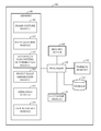
- FIG. 1 illustrates one example of an imaging system 100 configured to obtain a single image having multiple, in focus, regions of interest.
- the illustrated embodiment is not meant to be limiting, but is rather illustrative of certain components in some embodiments.
- System 100 may include a variety of other components for other functions which are not shown for clarity of the illustrated components.
- the imaging system 100 may include an imaging device 110 and an electronic display 130 .
- electronic display 130 may be any flat panel display technology, such as an LED, LCD, plasma, or projection screen.
- Electronic display 130 may be coupled to the processor 120 for receiving information for visual display to a user. Such information may include, but is not limited to, visual representations of files stored in a memory location, software applications installed on the processor 120 , user interfaces, and network-accessible content objects.
- Processor 120 may be a general purpose processing unit or it may be a processor specially designed for imaging applications for a handheld electronic device. As shown, the processor 120 is connected to, and in data communication with, program memory 140 and a working memory 135 . In some embodiments, the working memory 135 may be incorporated in the processor 120 , for example, cache memory. The working memory 135 may also be a component separate from the processor 120 and coupled to the processor 120 , for example, one or more RAM or DRAM components. In other words, although FIG. 1 illustrates two memory components, including memory component 140 comprising several modules and a separate memory 135 comprising a working memory, one with skill in the art would recognize several embodiments utilizing different memory architectures.
- a design may utilize ROM or static RAM memory for the storage of processor instructions implementing the modules contained in memory 140 .
- the processor instructions may then be loaded into RAM to facilitate execution by the processor.
- working memory 135 may be a RAM memory, with instructions loaded into working memory 135 before execution by the processor 120 .
- the program memory 140 stores an image capture module 145 , a region of interest (ROI) suggestion module 150 , an autofocus parameters determination module 155 , a single image generation module 160 , operating system 165 , and a user interface module 170 . These modules may include instructions that configure the processor 120 to perform various image processing and device management tasks.
- Program memory 140 can be any suitable computer-readable storage medium, such as a non-transitory storage medium.
- Working memory 135 may be used by processor 120 to store a working set of processor instructions contained in the modules of memory 140 . Alternatively, working memory 135 may also be used by processor 120 to store dynamic data created during the operation of imaging system 100 .
- the processor 120 may be configured by several modules stored in the memory 140 .
- the process 120 can run instructions stored in modules in the memory 140 .
- Image capture module 145 may include instructions that configure the processor 120 to obtain images from the imaging device. Therefore, processor 120 , along with image capture module 145 , imaging device 110 , and working memory 135 , represent one means for obtaining image sensor data of one or more regions of interest.
- Memory 140 may also contain autofocus parameters determination module 155 .
- the autofocus parameters determination module 155 may include instructions that configure the processor 120 to perform an autofocus function and calculate and store the autofocus parameters for each of the identified regions of interest. For example, if three regions of interest are selected, the processor 120 may be instructed by the autofocus parameters determination module 155 to calculate the autofocus parameters corresponding to each of region of interest and store the autofocus parameters in the working memory 135 or storage device 125 . The processor 120 then can be instructed by the image capture module 145 to, using the imagine device 110 , capture single images of each region of interest based on the autofocus parameters of each region of interest. Therefore, processor 120 , along with ROI suggestion module 150 , autofocus parameters determination module 155 , and working memory 135 represent one means for calculating and storing autofocus parameters for each selected region of interest.
- Memory 140 may also contain a single image generation module 160 .
- the single image generation module 160 illustrated in FIG. 1 may include instructions that configure the processor 120 to generate a single, multi-focus image containing the multiple regions of interest identified by the ROI suggestion module 150 . For example, if three regions of interest are selected, autofocus parameters are calculated and stored for each region of interest, and multiple images are taken in which each region of interest in focus in one of the multiple images, the processor 120 may be instructed by the single image generation module 160 to generate a single, multi-focus image by seamlessly integrating the multiple images. Therefore, processor 120 , along with ROI suggestion module 150 , single image generation module 160 , and working memory 135 represent one means for generating a single image from multiple images of regions of interest.
- Memory 140 may also contain user interface module 170 .
- the user interface module 170 illustrated in FIG. 1 may include instructions that configure the processor 120 to provide a collection of on-display objects and soft controls that allow the user to interact with the device, such as allowing the user to select regions of interest identified and displayed in a preview mode of the imaging device.
- the user interface module 170 also allows applications to interact with the rest of the system.
- An operating system module 165 may also reside in memory 140 and operate with processor 120 to manage the memory and processing resources of the system 100 .
- operating system 165 may include device drivers to manage hardware resources such as the electronic display 130 or imaging device 110 .
- instructions contained in the ROI suggestion module 150 and autofocus parameters determination module 155 may not interact with these hardware resources directly, but instead interact through standard subroutines or APIs located in operating system 165 . Instructions within operating system 165 may then interact directly with these hardware components.
- Processor 120 may write data to storage module 125 . While storage module 125 is represented graphically as a traditional disk drive, those with skill in the art would understand multiple embodiments could include either a disk-based storage device or one of several other types of storage mediums, including a memory disk, USB drive, flash drive, remotely connected storage medium, virtual disk driver, or the like.
- FIG. 1 depicts a device comprising separate components to include a processor, imaging device, electronic display, and memory
- processor imaging device
- electronic display electronic display
- memory any suitable type of memory
- FIG. 1 depicts a device comprising separate components to include a processor, imaging device, electronic display, and memory
- these separate components may be combined in a variety of ways to achieve particular design objectives.
- the memory components may be combined with processor components to save cost and improve performance.
- FIG. 1 illustrates two memory components, including memory component 140 comprising several modules and a separate memory 135 comprising a working memory
- a design may utilize ROM or static RAM memory for the storage of processor instructions implementing the modules contained in memory 140 .
- processor instructions may be read at system startup from a disk storage device that is integrated into imaging system 100 or connected via an external device port. The processor instructions may then be loaded into RAM to facilitate execution by the processor.
- working memory 135 may be a RAM memory, with instructions loaded into working memory 135 before execution by the processor 120 .
- Embodiments of the invention relate to a process for multi-focus imaging, which can include recommending a plurality of candidate regions of interest within a single scene of interest to the user, receiving input regarding determining candidate region of interest within a scene, receiving input as to the selection of the desired regions of interest to be captured within the single scene, obtaining multiple images based on autofocus parameters associated with the desired or selected regions of interest, and seamlessly integrating the multiple images into a single, multi-focus image. That is, for example, a single image that has multiple regions at different object planes (or depths), each of which are in-focus in the integrated image.
- the examples may be described as a process, which is depicted as a flowchart, a flow diagram, a finite state diagram, a structure diagram, or a block diagram. Although a flowchart may describe the operations as a sequential process, many of the operations can be performed in parallel, or concurrently, and the process can be repeated. In addition, the order of the operations may be re-arranged.
- a process is terminated when its operations are completed.
- a process may correspond to a method, a function, a procedure, a subroutine, a subprogram, etc. When a process corresponds to a software function, its termination corresponds to a return of the function to the calling function or the main function.
- FIG. 2 illustrates one embodiment of a process 200 to configure an electronic device having an imaging device (such as imaging device 110 shown in FIG. 1 ) to perform multi-focus imaging that may be implemented in one or more of the modules depicted in FIG. 1 .
- the process 200 may be run on a processor, for example, processor 120 ( FIG. 1 ), and on other components illustrated in FIG. 1 that are stored in memory 140 or that are incorporated in other hardware or software.
- a preview mode may include displaying on an electronic display, for example, electronic display 130 ( FIG. 1 ) the scene as viewed by the lens of the imaging device 110 .
- the electronic device may be a handheld communication device, e.g., a cellular phone or “smartphone,” or a mobile personal data assistant (PDA) including a tablet computer.
- PDA mobile personal data assistant
- the user may operate the camera of a mobile device in a preview mode to determine whether or not to capture an image.
- the user may operate the camera of the mobile device in a preview mode to determine what regions of interest the user would like to capture in a multi-focus image.
- face detection may determine that three faces appear at various depths within the scene.
- object tracking might identify two or more items within a scene, for example, a pail, sand castle, and a bird on a beach.
- the user may select one or more of the faces displayed in a preview mode by selecting each face on the touchscreen.
- the user may also use a mouse, pointer, or button to select a plurality of regions of interest.
- FIG. 3 One example of a user interface illustrating a user selecting multiple regions of interest is shown in FIG. 3 .
- the user may direct a pointer to each of the multiple regions of interest.
- the user has selected the “Focus” text, the “Dragon” text, the knight chess piece, and the flowers.
- Process 200 next transitions to block 212 , wherein the processor is instructed to determine autofocus parameters related to the selected ROIs.
- the processor may be instructed to perform an autofocus function of the imaging device 110 to determine the autofocus parameters such that each of the selected regions of interest is in focus.
- the autofocus parameters are the set of commands sent to a sensor driver of the processor 120 .
- the sensor driver includes settings or instructions to move the lens position of the imaging device 110 .
- the sensor driver could include parameters to adjust the autofocus, auto white balance, and auto exposure settings of the imaging device 110 .
- the autofocus parameters are preferably determined by the underlying autofocus, auto white balance, and auto exposure settings algorithm and may be based on the imaging device 100 .
- the autofocus function could calculate the autofocus parameters for each of the faces identified as regions of interest within the scene and selected by the user as desired regions of interest for a multi-focus image.
- Process 200 next transitions to block 214 , wherein the processor is instructed to capture one or more images, each image containing one of the regions of interest in focus, using the autofocus parameters associated with each region of interest. For example, a separate image may be captured of each of the three faces identified as regions of interest by the user.
- Process 200 then transitions to block 216 , wherein the processor is instructed to generate a single image from the one or more images captured of the multiple regions of interest.
- FIG. 4 One example of multi-focus single image is shown in FIG. 4 .
- a single image may be generated by combining two or more images captured by the imaging device 110 as discussed above and “stitching” the images together using any known image combining algorithm.
- a single image may be acquired by applying image alignment, image registration, and image blending techniques as known in the art to the two or more images captured by the imaging device 110 with different focus settings.
- process 200 transitions to block 218 and ends.
- any disclosure of an operation of an apparatus having a particular feature is also expressly intended to disclose a method having an analogous feature (and vice versa), and any disclosure of an operation of an apparatus according to a particular configuration is also expressly intended to disclose a method according to an analogous configuration (and vice versa).
- configuration may be used in reference to a method, apparatus, and/or system as indicated by its particular context.
- method method
- process processing
- procedure and “technique”
- apparatus and “device” are also used generically and interchangeably unless otherwise indicated by the particular context.
- DSP digital signal processor
- ASIC application specific integrated circuit
- FPGA field programmable gate array
- a general purpose processor may be a microprocessor, but in the alternative, the processor may be any conventional processor, controller, microcontroller, or state machine.
- a processor may also be implemented as a combination of computing devices, e.g., a combination of a DSP and a microprocessor, a plurality of microprocessors, one or more microprocessors in conjunction with a DSP core, or any other such configuration.
- a software module may reside in RAM memory, flash memory, ROM memory, EPROM memory, EEPROM memory, registers, hard disk, a removable disk, a CD-ROM, or any other form of non-transitory storage medium known in the art.
- An exemplary computer-readable storage medium is coupled to the processor such the processor can read information from, and write information to, the computer-readable storage medium.
- the storage medium may be integral to the processor.
- the processor and the storage medium may reside in an ASIC.
- the ASIC may reside in a user terminal, camera, or other device.
- the processor and the storage medium may reside as discrete components in a user terminal, camera, or other device.
Priority Applications (10)
| Application Number | Priority Date | Filing Date | Title |
|---|---|---|---|
| US14/244,595 US9538065B2 (en) | 2014-04-03 | 2014-04-03 | System and method for multi-focus imaging |
| PCT/US2015/022418 WO2015153218A1 (en) | 2014-04-03 | 2015-03-25 | System and method for multi-focus imaging |
| CA2941143A CA2941143C (en) | 2014-04-03 | 2015-03-25 | System and method for multi-focus imaging |
| JP2016560451A JP6594897B2 (ja) | 2014-04-03 | 2015-03-25 | 多焦点イメージングのためのシステムおよび方法 |
| CN201910877502.5A CN110572574A (zh) | 2014-04-03 | 2015-03-25 | 用于多焦点成像的系统和方法 |
| ES15716630T ES2768712T3 (es) | 2014-04-03 | 2015-03-25 | Sistema y procedimiento para la formación de imágenes de enfoque múltiple |
| KR1020167027107A KR102326718B1 (ko) | 2014-04-03 | 2015-03-25 | 다-초점 이미징을 위한 시스템 및 방법 |
| CN201580014123.3A CN106134176B (zh) | 2014-04-03 | 2015-03-25 | 用于多焦点成像的系统和方法 |
| BR112016023059-0A BR112016023059B1 (pt) | 2014-04-03 | 2015-03-25 | Sistema e método para imagens multifocais |
| EP15716630.7A EP3127320B1 (en) | 2014-04-03 | 2015-03-25 | System and method for multi-focus imaging |
Applications Claiming Priority (1)
| Application Number | Priority Date | Filing Date | Title |
|---|---|---|---|
| US14/244,595 US9538065B2 (en) | 2014-04-03 | 2014-04-03 | System and method for multi-focus imaging |
Publications (2)
| Publication Number | Publication Date |
|---|---|
| US20150288870A1 US20150288870A1 (en) | 2015-10-08 |
| US9538065B2 true US9538065B2 (en) | 2017-01-03 |
Family
ID=52875272
Family Applications (1)
| Application Number | Title | Priority Date | Filing Date |
|---|---|---|---|
| US14/244,595 Active 2034-04-29 US9538065B2 (en) | 2014-04-03 | 2014-04-03 | System and method for multi-focus imaging |
Country Status (8)
| Country | Link |
|---|---|
| US (1) | US9538065B2 (ja) |
| EP (1) | EP3127320B1 (ja) |
| JP (1) | JP6594897B2 (ja) |
| KR (1) | KR102326718B1 (ja) |
| CN (2) | CN110572574A (ja) |
| CA (1) | CA2941143C (ja) |
| ES (1) | ES2768712T3 (ja) |
| WO (1) | WO2015153218A1 (ja) |
Families Citing this family (22)
| Publication number | Priority date | Publication date | Assignee | Title |
|---|---|---|---|---|
| US10558848B2 (en) | 2017-10-05 | 2020-02-11 | Duelight Llc | System, method, and computer program for capturing an image with correct skin tone exposure |
| US20170054897A1 (en) * | 2015-08-21 | 2017-02-23 | Samsung Electronics Co., Ltd. | Method of automatically focusing on region of interest by an electronic device |
| TWI706181B (zh) * | 2015-09-11 | 2020-10-01 | 新加坡商海特根微光學公司 | 具有自動對焦控制的成像裝置 |
| US10033917B1 (en) | 2015-11-13 | 2018-07-24 | Apple Inc. | Dynamic optical shift/tilt lens |
| CN105528786B (zh) | 2015-12-04 | 2019-10-01 | 小米科技有限责任公司 | 图像处理方法及装置 |
| US10630903B2 (en) * | 2018-01-12 | 2020-04-21 | Qualcomm Incorporated | Systems and methods for image exposure |
| US10948983B2 (en) * | 2018-03-21 | 2021-03-16 | Samsung Electronics Co., Ltd. | System and method for utilizing gaze tracking and focal point tracking |
| WO2020042126A1 (zh) * | 2018-08-30 | 2020-03-05 | 华为技术有限公司 | 一种对焦装置、方法及相关设备 |
| US10848832B2 (en) * | 2018-09-11 | 2020-11-24 | Opentv, Inc. | Selection interface with synchronized suggestion elements |
| KR102592595B1 (ko) * | 2018-12-07 | 2023-10-23 | 한국전자통신연구원 | 영상 내 문자 자동번역 시스템 및 방법 |
| CN109561255B (zh) * | 2018-12-20 | 2020-11-13 | 惠州Tcl移动通信有限公司 | 终端拍照方法、装置及存储介质 |
| US10887514B2 (en) * | 2018-12-21 | 2021-01-05 | Fuji Xerox Co., Ltd. | System and method of providing gaze and awareness for ultra wide and 360 cameras |
| CN109495689B (zh) * | 2018-12-29 | 2021-04-13 | 北京旷视科技有限公司 | 一种拍摄方法、装置、电子设备及存储介质 |
| CN109948606B (zh) * | 2019-02-20 | 2023-09-19 | 深圳威尔视觉传媒有限公司 | 基于图像识别自动获取焦点的方法和相关装置 |
| CN109995999A (zh) * | 2019-03-14 | 2019-07-09 | Oppo广东移动通信有限公司 | 场景识别方法、装置、电子设备及存储介质 |
| US10984513B1 (en) | 2019-09-30 | 2021-04-20 | Google Llc | Automatic generation of all-in-focus images with a mobile camera |
| CN111246106B (zh) * | 2020-01-22 | 2021-08-03 | 维沃移动通信有限公司 | 图像处理方法、电子设备及计算机可读存储介质 |
| CN111263072A (zh) * | 2020-02-26 | 2020-06-09 | Oppo广东移动通信有限公司 | 一种拍摄控制方法、装置及计算机可读存储介质 |
| CN113866974A (zh) * | 2020-06-29 | 2021-12-31 | 深圳辉煌耀强科技有限公司 | 应用于宫颈细胞图像的聚焦方法、装置、设备及存储介质 |
| US11272097B2 (en) * | 2020-07-30 | 2022-03-08 | Steven Brian Demers | Aesthetic learning methods and apparatus for automating image capture device controls |
| CN112839166B (zh) * | 2020-12-02 | 2023-08-22 | 维沃移动通信(杭州)有限公司 | 拍摄方法、装置及电子设备 |
| CN114788254B (zh) * | 2020-12-16 | 2024-04-30 | 深圳市大疆创新科技有限公司 | 辅助对焦方法、装置及系统 |
Citations (9)
| Publication number | Priority date | Publication date | Assignee | Title |
|---|---|---|---|---|
| US6975352B2 (en) | 2000-12-18 | 2005-12-13 | Xerox Corporation | Apparatus and method for capturing a composite digital image with regions of varied focus and magnification |
| US20070126919A1 (en) | 2003-01-03 | 2007-06-07 | Chulhee Lee | Cameras capable of providing multiple focus levels |
| US20090059061A1 (en) * | 2007-08-30 | 2009-03-05 | Samsung Techwin Co., Ltd. | Digital photographing apparatus and method using face recognition function |
| US7711259B2 (en) | 2006-07-14 | 2010-05-04 | Aptina Imaging Corporation | Method and apparatus for increasing depth of field for an imager |
| US20110267530A1 (en) | 2008-09-05 | 2011-11-03 | Chun Woo Chang | Mobile terminal and method of photographing image using the same |
| US8154647B2 (en) | 2008-03-05 | 2012-04-10 | Applied Minds, Llc | Automated extended depth of field imaging apparatus and method |
| US20120120277A1 (en) * | 2010-11-16 | 2012-05-17 | Apple Inc. | Multi-point Touch Focus |
| US20120120269A1 (en) | 2010-11-11 | 2012-05-17 | Tessera Technologies Ireland Limited | Rapid auto-focus using classifier chains, mems and/or multiple object focusing |
| US20140092272A1 (en) * | 2012-09-28 | 2014-04-03 | Pantech Co., Ltd. | Apparatus and method for capturing multi-focus image using continuous auto focus |
Family Cites Families (10)
| Publication number | Priority date | Publication date | Assignee | Title |
|---|---|---|---|---|
| JP4218720B2 (ja) * | 2006-09-22 | 2009-02-04 | ソニー株式会社 | 撮像装置、および撮像装置制御方法、並びにコンピュータ・プログラム |
| CN101272511B (zh) * | 2007-03-19 | 2010-05-26 | 华为技术有限公司 | 图像深度信息和图像像素信息的获取方法及装置 |
| KR100811796B1 (ko) * | 2007-03-30 | 2008-03-10 | 삼성전자주식회사 | 휴대 단말기 및 그의 초점 정보를 이용한 영상 표시 방법 |
| JP5114175B2 (ja) * | 2007-12-11 | 2013-01-09 | 株式会社リコー | 光走査装置及びカラー画像形成装置 |
| JP4513905B2 (ja) * | 2008-06-27 | 2010-07-28 | ソニー株式会社 | 信号処理装置、信号処理方法、プログラム及び記録媒体 |
| JP5197785B2 (ja) * | 2011-03-30 | 2013-05-15 | キヤノン株式会社 | 画像処理装置、撮像システム、画像処理システム |
| JP5220157B2 (ja) * | 2011-04-01 | 2013-06-26 | キヤノン株式会社 | 情報処理装置及びその制御方法、プログラム、並びに記憶媒体 |
| US9501834B2 (en) * | 2011-08-18 | 2016-11-22 | Qualcomm Technologies, Inc. | Image capture for later refocusing or focus-manipulation |
| KR101797040B1 (ko) * | 2011-11-28 | 2017-11-13 | 삼성전자주식회사 | 디지털 촬영 장치 및 이의 제어 방법 |
| JP5662511B2 (ja) * | 2013-04-10 | 2015-01-28 | シャープ株式会社 | 撮像装置 |
-
2014
- 2014-04-03 US US14/244,595 patent/US9538065B2/en active Active
-
2015
- 2015-03-25 WO PCT/US2015/022418 patent/WO2015153218A1/en active Application Filing
- 2015-03-25 CN CN201910877502.5A patent/CN110572574A/zh active Pending
- 2015-03-25 CA CA2941143A patent/CA2941143C/en active Active
- 2015-03-25 EP EP15716630.7A patent/EP3127320B1/en active Active
- 2015-03-25 JP JP2016560451A patent/JP6594897B2/ja active Active
- 2015-03-25 ES ES15716630T patent/ES2768712T3/es active Active
- 2015-03-25 KR KR1020167027107A patent/KR102326718B1/ko active IP Right Grant
- 2015-03-25 CN CN201580014123.3A patent/CN106134176B/zh active Active
Patent Citations (9)
| Publication number | Priority date | Publication date | Assignee | Title |
|---|---|---|---|---|
| US6975352B2 (en) | 2000-12-18 | 2005-12-13 | Xerox Corporation | Apparatus and method for capturing a composite digital image with regions of varied focus and magnification |
| US20070126919A1 (en) | 2003-01-03 | 2007-06-07 | Chulhee Lee | Cameras capable of providing multiple focus levels |
| US7711259B2 (en) | 2006-07-14 | 2010-05-04 | Aptina Imaging Corporation | Method and apparatus for increasing depth of field for an imager |
| US20090059061A1 (en) * | 2007-08-30 | 2009-03-05 | Samsung Techwin Co., Ltd. | Digital photographing apparatus and method using face recognition function |
| US8154647B2 (en) | 2008-03-05 | 2012-04-10 | Applied Minds, Llc | Automated extended depth of field imaging apparatus and method |
| US20110267530A1 (en) | 2008-09-05 | 2011-11-03 | Chun Woo Chang | Mobile terminal and method of photographing image using the same |
| US20120120269A1 (en) | 2010-11-11 | 2012-05-17 | Tessera Technologies Ireland Limited | Rapid auto-focus using classifier chains, mems and/or multiple object focusing |
| US20120120277A1 (en) * | 2010-11-16 | 2012-05-17 | Apple Inc. | Multi-point Touch Focus |
| US20140092272A1 (en) * | 2012-09-28 | 2014-04-03 | Pantech Co., Ltd. | Apparatus and method for capturing multi-focus image using continuous auto focus |
Non-Patent Citations (1)
| Title |
|---|
| International Search Report and Written Opinion-PCT/US2015/022418-ISA/EPO-Jun. 15, 2015. |
Also Published As
| Publication number | Publication date |
|---|---|
| CN106134176B (zh) | 2019-10-01 |
| CA2941143C (en) | 2023-04-11 |
| BR112016023059A8 (pt) | 2021-07-13 |
| JP6594897B2 (ja) | 2019-10-23 |
| CN106134176A (zh) | 2016-11-16 |
| CN110572574A (zh) | 2019-12-13 |
| BR112016023059A2 (pt) | 2017-08-15 |
| US20150288870A1 (en) | 2015-10-08 |
| WO2015153218A1 (en) | 2015-10-08 |
| JP2017518658A (ja) | 2017-07-06 |
| EP3127320A1 (en) | 2017-02-08 |
| KR20160140684A (ko) | 2016-12-07 |
| KR102326718B1 (ko) | 2021-11-15 |
| CA2941143A1 (en) | 2015-10-08 |
| EP3127320B1 (en) | 2019-10-23 |
| ES2768712T3 (es) | 2020-06-23 |
Similar Documents
| Publication | Publication Date | Title |
|---|---|---|
| US9538065B2 (en) | System and method for multi-focus imaging | |
| RU2612892C2 (ru) | Способ автоматической фокусировки и устройство автоматической фокусировки | |
| US9998651B2 (en) | Image processing apparatus and image processing method | |
| US10277889B2 (en) | Method and system for depth estimation based upon object magnification | |
| US9912853B2 (en) | Switching between cameras of an electronic device | |
| US9390532B2 (en) | Object removal from an image | |
| JP2017518658A5 (ja) | ||
| US10317777B2 (en) | Automatic zooming method and apparatus | |
| KR102360424B1 (ko) | 얼굴 검출 방법, 영상 처리 방법, 얼굴 검출 장치 및 이를 포함하는 전자 시스템 | |
| CN107172347B (zh) | 一种拍照方法及终端 | |
| US9489715B2 (en) | Image display apparatus and image display method | |
| US9921054B2 (en) | Shooting method for three dimensional modeling and electronic device supporting the same | |
| US20150199098A1 (en) | Method for setting image capture conditions and electronic device performing the same | |
| EP2919187A2 (en) | Image processing apparatus and image processing method | |
| JP6175583B1 (ja) | 画像処理装置、実寸法表示方法、及び実寸法表示処理プログラム | |
| CN107105158B (zh) | 一种拍照方法及移动终端 | |
| JP6679430B2 (ja) | 撮像装置、撮像装置の制御方法及びプログラム | |
| US20230144172A1 (en) | User interface for camera focus | |
| BR112016023059B1 (pt) | Sistema e método para imagens multifocais | |
| KR20240067963A (ko) | 카메라 포커스를 위한 사용자 인터페이스 |
Legal Events
| Date | Code | Title | Description |
|---|---|---|---|
| AS | Assignment |
Owner name: QUALCOMM INCORPORATED, CALIFORNIA Free format text: ASSIGNMENT OF ASSIGNORS INTEREST;ASSIGNORS:NAGARAJA, ADARSH HOSAAGRAHARA;LIU, WEILIANG;LIU, SHIZHONG;REEL/FRAME:032599/0421 Effective date: 20140327 |
|
| FEPP | Fee payment procedure |
Free format text: PAYOR NUMBER ASSIGNED (ORIGINAL EVENT CODE: ASPN); ENTITY STATUS OF PATENT OWNER: LARGE ENTITY |
|
| STCF | Information on status: patent grant |
Free format text: PATENTED CASE |
|
| MAFP | Maintenance fee payment |
Free format text: PAYMENT OF MAINTENANCE FEE, 4TH YEAR, LARGE ENTITY (ORIGINAL EVENT CODE: M1551); ENTITY STATUS OF PATENT OWNER: LARGE ENTITY Year of fee payment: 4 |