US9538022B2 - Method for applying cloud-based time-lapse imaging systems - Google Patents
Method for applying cloud-based time-lapse imaging systems Download PDFInfo
- Publication number
- US9538022B2 US9538022B2 US14/597,195 US201514597195A US9538022B2 US 9538022 B2 US9538022 B2 US 9538022B2 US 201514597195 A US201514597195 A US 201514597195A US 9538022 B2 US9538022 B2 US 9538022B2
- Authority
- US
- United States
- Prior art keywords
- time
- camera device
- camera
- still image
- image
- Prior art date
- Legal status (The legal status is an assumption and is not a legal conclusion. Google has not performed a legal analysis and makes no representation as to the accuracy of the status listed.)
- Expired - Fee Related
Links
- 238000000034 method Methods 0.000 title claims abstract description 40
- 238000003384 imaging method Methods 0.000 title claims abstract description 28
- 238000012545 processing Methods 0.000 claims description 12
- 238000012546 transfer Methods 0.000 abstract description 3
- 238000010586 diagram Methods 0.000 description 8
- 238000006243 chemical reaction Methods 0.000 description 3
- 230000008569 process Effects 0.000 description 3
- 230000007246 mechanism Effects 0.000 description 2
- 230000004044 response Effects 0.000 description 2
- 229920006395 saturated elastomer Polymers 0.000 description 2
- 239000004065 semiconductor Substances 0.000 description 2
- 230000006399 behavior Effects 0.000 description 1
- 230000000295 complement effect Effects 0.000 description 1
- 238000003306 harvesting Methods 0.000 description 1
- 230000008676 import Effects 0.000 description 1
- 230000007774 longterm Effects 0.000 description 1
- KJFBVJALEQWJBS-XUXIUFHCSA-N maribavir Chemical compound CC(C)NC1=NC2=CC(Cl)=C(Cl)C=C2N1[C@H]1O[C@@H](CO)[C@H](O)[C@@H]1O KJFBVJALEQWJBS-XUXIUFHCSA-N 0.000 description 1
- 238000012986 modification Methods 0.000 description 1
- 230000004048 modification Effects 0.000 description 1
- 238000012544 monitoring process Methods 0.000 description 1
- 230000003287 optical effect Effects 0.000 description 1
- 238000012805 post-processing Methods 0.000 description 1
- 238000012795 verification Methods 0.000 description 1
- 230000000007 visual effect Effects 0.000 description 1
Images


Classifications
-
- H—ELECTRICITY
- H04—ELECTRIC COMMUNICATION TECHNIQUE
- H04N—PICTORIAL COMMUNICATION, e.g. TELEVISION
- H04N1/00—Scanning, transmission or reproduction of documents or the like, e.g. facsimile transmission; Details thereof
- H04N1/00127—Connection or combination of a still picture apparatus with another apparatus, e.g. for storage, processing or transmission of still picture signals or of information associated with a still picture
- H04N1/00204—Connection or combination of a still picture apparatus with another apparatus, e.g. for storage, processing or transmission of still picture signals or of information associated with a still picture with a digital computer or a digital computer system, e.g. an internet server
- H04N1/00244—Connection or combination of a still picture apparatus with another apparatus, e.g. for storage, processing or transmission of still picture signals or of information associated with a still picture with a digital computer or a digital computer system, e.g. an internet server with a server, e.g. an internet server
-
- H—ELECTRICITY
- H04—ELECTRIC COMMUNICATION TECHNIQUE
- H04N—PICTORIAL COMMUNICATION, e.g. TELEVISION
- H04N1/00—Scanning, transmission or reproduction of documents or the like, e.g. facsimile transmission; Details thereof
- H04N1/00127—Connection or combination of a still picture apparatus with another apparatus, e.g. for storage, processing or transmission of still picture signals or of information associated with a still picture
- H04N1/00129—Connection or combination of a still picture apparatus with another apparatus, e.g. for storage, processing or transmission of still picture signals or of information associated with a still picture with a display device, e.g. CRT or LCD monitor
-
- H—ELECTRICITY
- H04—ELECTRIC COMMUNICATION TECHNIQUE
- H04N—PICTORIAL COMMUNICATION, e.g. TELEVISION
- H04N1/00—Scanning, transmission or reproduction of documents or the like, e.g. facsimile transmission; Details thereof
- H04N1/00127—Connection or combination of a still picture apparatus with another apparatus, e.g. for storage, processing or transmission of still picture signals or of information associated with a still picture
- H04N1/00204—Connection or combination of a still picture apparatus with another apparatus, e.g. for storage, processing or transmission of still picture signals or of information associated with a still picture with a digital computer or a digital computer system, e.g. an internet server
- H04N1/00209—Transmitting or receiving image data, e.g. facsimile data, via a computer, e.g. using e-mail, a computer network, the internet, I-fax
-
- H—ELECTRICITY
- H04—ELECTRIC COMMUNICATION TECHNIQUE
- H04N—PICTORIAL COMMUNICATION, e.g. TELEVISION
- H04N23/00—Cameras or camera modules comprising electronic image sensors; Control thereof
- H04N23/60—Control of cameras or camera modules
- H04N23/66—Remote control of cameras or camera parts, e.g. by remote control devices
- H04N23/661—Transmitting camera control signals through networks, e.g. control via the Internet
-
- H04N5/23203—
-
- H—ELECTRICITY
- H04—ELECTRIC COMMUNICATION TECHNIQUE
- H04N—PICTORIAL COMMUNICATION, e.g. TELEVISION
- H04N5/00—Details of television systems
- H04N5/76—Television signal recording
- H04N5/765—Interface circuits between an apparatus for recording and another apparatus
- H04N5/77—Interface circuits between an apparatus for recording and another apparatus between a recording apparatus and a television camera
Definitions
- the present invention relates to a method for applying cloud-based time-lapse imaging systems. More particularly, the present invention relates to a method for applying cloud-based time-lapse imaging systems, in which the cloud-based time-lapse imaging systems upload images via a network after the images were captured.
- Time-lapse video is a film obtained by a special cinematography technique. Time-lapse videos are usually captured at a low frame rate but played at a normal frame rate. Thus, the time is virtually lapsing in time-lapse videos. Time-lapse videos enable an audience to observe the long-term changes in motion in a short period of time. For example, an image of a dynamic scene may be captured once every 6 seconds in a half-hour time span, and then played back at a frame rate of 30 frames per second. That is, the image is displayed at 180 times the normal speed. An audience therefore may observe the changes within that half-hour time span with a 10-second running length video.
- time-lapse imaging systems well-known in the art combine a camera and an intervalometer to record time-lapse videos.
- a user may establish a time-lapse imaging system by mounting the camera at one place and setting the intervalometer with instructions, such as the working duration and capture frequency, and then leave the time-lapse imaging system alone for the following processes. Based on the instructions, the timer would automatically release the shutter in the camera to capture a still image at a time interval and the still images captured by the camera would be further saved on a memory module (e.g., a memory card). The user may simply go back to that place and harvest the camera and the memory card after the working duration is saturated, and the lapse-time video retrieved from the memory card would then be displayed on a computer or a TV.
- a memory module e.g., a memory card
- Video editing software usually provides numerous filters which can be applied on a video and transform the video into a time-lapse video.
- a user may simply import any common video into the video editing software for converting the video into a time-lapse video.
- the video editing software would automatically extract some specific frames in the video based on the pre-determined conditions given by the user and regroup these specific frames into a time-lapse video.
- Time-lapse videos are characterized in that they are able to display a long event in a short time. This characteristic allows the time-lapse video to be used in the field of art to create a special visual effect, and be used in some other fields to produce economic values.
- surveillance cameras are configured to monitor and record image for a very long time, and they provide both real-time images and camera recordings to users.
- Time-lapse video is an ideal storage format for preserving the camera recordings in relative industries.
- applying the aforementioned techniques to these relative industries would lead to some shortcomings.
- the time-lapse imaging systems well-known in the art store camera recordings mostly on a memory card in the camera. It is impossible to obtain these camera recordings immediately, and the memory card in the camera is exposed to the risk of being stolen.
- the video editing software As for the video editing software, it requires a raw video, which occupies a significant amount of memory space, for editing. Thus the memory card needs to be clean up frequently to release more space for new videos. Furthermore, the video editing software requires an additional step, the step for the post-processing of video, to create a time-lapse video.
- At least one embodiment of the present invention relates to a method for applying cloud-based time-lapse imaging systems.
- the method applies time-lapse photography in a secure and convenient way and provides a mechanism for responding to requests rapidly.
- the method is initiated with a camera device receiving a recording command.
- the camera device analyzes the recording command and obtains a start time, an end time, and a first time interval from the recording command.
- the camera device would capture a first image set according to the request. More particularly, the camera device would capture a first still image at a first time point and upload the first still image to a server, capture a second still image at a second time point (i.e., the time point spaced one first time interval away from the first time point) and upload the second still image to the server, and repeat the aforementioned behavior until the first image set is saturated.
- At least two still images in the server would be transmitted to a display device after the server obtained the at least two still images, and the display device would further display the at least two still image at a second time interval sequentially.
- the second time interval is shorter than the first time interval.
- At least one embodiment of the present invention is characterized in that the cloud-based time-lapsed imaging system comprises a camera device without any built-in memory module, such as the memory card, the hard disk, or the compact disc.
- the method for applying cloud-based time-lapse imaging systems in the embodiment uploads each still image to the server right after the still image is taken.
- At least one embodiment of the present invention is characterized in that the cloud-based time-lapsed imaging system comprises a camera device without any image conversion module for converting still images into dynamic images.
- the method for applying cloud-based time-lapse imaging systems in the embodiment uploads each still image to the server right after the still image is taken, and the still images are merged into a dynamic video on the server.
- At least one embodiment of the present invention is characterized in that the cloud-based time-lapsed imaging system requires a low bandwidth and light data usage to operate.
- the method for applying cloud-based time-lapse imaging systems in the embodiment captures and uploads still images regularly instead of streaming a full video, which usually demands a high bandwidth and large data usage, to the server.
- At least one embodiment of the present invention is characterized in that the display device in the cloud-based time-lapsed imaging system is able to obtain the time-lapse videos anytime and anywhere.
- the method for applying cloud-based time-lapse imaging systems in the embodiment uploads each still image to the server right after the still image is taken. Therefore, the display device may request the server to transmit still images existed and stored in the server to the display device while not interrupting the image capture process of the camera device.
- At least one embodiment of the present invention is characterized in that the method for applying cloud-based time-lapsed imaging systems provides several advantages, e.g., high security, convenience, and quick response to requests.
- the method in the embodiment may be used to produce time-lapse video and be applied in the security and surveillance industries.
- FIG. 1 is a schematic diagram illustrating a cloud-based time-lapse imaging system, in accordance with at least one embodiment of the present invention.
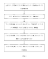
- FIG. 2 is a flow diagram illustrating a method for applying cloud-based time-lapse imaging systems, in accordance with at least one embodiment of the present invention.
- FIG. 3 is a flow diagram illustrating a method for recording time-lapse images by camera devices, in accordance with the present invention.
- FIG. 4 is a flow diagram illustrating a method for playing time-lapse images on display devices, in accordance with the present invention.
- At least one embodiment in accordance with the present invention relates to a method for applying cloud-based time-lapse imaging systems.
- the embodiments and drawings provided here show different aspects of the present invention. However, the present invention is limited to neither any embodiment nor any drawing thereof.
- a camera device is able to obtain some information, including a start time, an end time, and a time interval, from a recording command. Within a time span defined by the start time and the end time, the camera device captures a still image and upload the still image to a server periodically (i.e., the time interval).
- the server may accumulate a plurality of still images and transfer the plurality of still images to a display device for presentation.
- FIG. 1 is a schematic diagram illustrating a cloud-based time-lapse imaging system, in accordance with at least one embodiment of the present invention.
- the cloud-based time-lapse imaging system comprises a display device 10 , a camera device 20 , and a server 30 , in which the display device 10 , the camera device 20 , and the server 30 are connected together by a network.
- the display device 10 may be a device such as a computer, a smart TV, a mobile phone, or a tablet.
- the camera device 20 may be a computer, a mobile phone, a tablet, a camera, a video camera, or a surveillance camera.
- the server 30 may be a cloud-based server or a time-lapse image server.
- the display device 10 , the camera device 20 , and the server 30 are paired by different networks.
- the display device 10 and the server 30 are connected together by a wired network or a telecommunication network, and the server 30 , however, is further connected to the camera device 20 via a Wi-Fi network.
- the camera device 10 in FIG. 1 further comprises a first transceiver 11 , a first processing module 12 , a display module 13 , and an input module 14 .
- the first transceiver 11 is configured to transmit and receive information, and it is able to connect with the camera device 20 and the server 30 via a wired network, a wireless network, or a telecommunication network.
- the display device 13 is configured to display images
- the input module 14 is configured to input a recording command for the camera device 20 and to input a play request for the server 30 .
- the first processing module 12 electrically connects to the first transceiver 11 , the display module 13 , and the input module 14 respectively, and it works as an information distribution center. In some embodiments, the first processing module 12 also works as an image conversion module for converting a plurality of still images into a dynamic image.
- the camera device 20 in FIG. 1 comprises a second transceiver 21 , a second processing module 22 , and an image capture module 23 .
- the second transceiver 21 is configured to transmit and receive information, and it is able to connect with the display device 10 and the server 30 via a wired network, a wireless network, or a telecommunication network.
- the image capture module 23 is configured to capture images. More particularly, the image capture module 23 comprises an optical image sensor such as a semiconductor charge-coupled device (CCD) or a complementary metal-oxide-semiconductor (CMOS).
- CCD semiconductor charge-coupled device
- CMOS complementary metal-oxide-semiconductor
- the second processing module 22 is configured to electrically connect with the second transceiver 21 and image capture module 23 respectively.
- the second processing module 22 is also configured to analyze a recording command and obtain a start time, an end time, and a time interval. In some embodiments, the second processing module 22 further works as an intervalometer to regulate the
- the server 30 in FIG. 1 comprises a third transceiver 31 , a third processing module 32 and memory module 33 .
- the third transceiver 31 is configured to transmit and receive information, and it is able to connect with the display device 10 and the camera device 20 via a wired network, a wireless network, or a telecommunication network.
- the memory module 33 is configured to store a user database and the still images transferred from the camera device 20 .
- the third processing module 32 is electrically connected with the third transceiver 31 and the memory module 33 respectively and works as an information distribution center.
- the third processing module 32 also works as an identity verification module which can utilize the user database to pair a display device 10 and a camera device 20 .
- the third processing module 32 also works as an image conversion module for converting a plurality of still images into a dynamic image by the cloud-computing power of the server 30 .
- FIG. 2 is a flow diagram illustrating a method for applying cloud-based time-lapse imaging systems, in accordance with at least one embodiment of the present invention.
- the embodied method initiates with a camera device receiving a recording command.
- the camera device obtains information including a start time, an end time, and a first time interval by analyzing the recording command.
- the camera device captures and uploads a plurality of still images to a server at the first time interval.
- the server thereafter transfers the plurality of still images to a display device, and then the display device displays the plurality of still images at a second time interval sequentially.
- FIG. 3 is a flow diagram illustrating a method for recording time-lapse images by camera devices, in accordance with the present invention.
- the embodied method initiates with a display device transmitting a recording command to a camera device.
- the camera device would follow the instructions in the recording command to capture and upload a first image set to a server.
- the first image set comprises a first still image, a second still image, a third still image . . . , and an N still image, in which N is a natural number.
- the server would store the still images for the subsequent uses after received these still images from the camera device.
- FIG. 4 is a flow diagram illustrating a method for playing time-lapse images by display devices, in accordance with the present invention.
- the embodied method initiates with a user sending a play request to a server by a display device.
- the server would retrieve a second image set requested by the play request.
- the server would further merge the still images in the second image set into a dynamic image at a frame rate by cloud computing. More particularly, the second image set is a subset of the first image set.
- the dynamic image would be streamed from the server to a display device and be presented on the display device.
- a smart phone is used as the display device and an IP cam monitoring the pet at home is used as the camera device.
- a user may submit a recording command by the smart phone and send the recording command to the IP cam via a remote server before the user left the office.
- the recording command is assigned to request a 20-second time-lapse video, condensed from a 30-minute time frame, about the pet at home from the IP cam. After that the IP cam had received the recording request, the IP cam would begin to study the recording command. In accordance with the instructions in the recording command, the IP cam would capture and upload an image to the remote server every 6 seconds.
- the user may decide to preview the video and submit a play request to the remote server by the smart phone during the commute back home.
- the remote server would then convert the images obtained so far into a time-lapse video by cloud computing and transmit the time-lapse video to the smart phone for the user via the telecommunication network.
- the server would automatically send a notification to the smart phone to inform the user that the process of recording a time-lapse video is fully completed.
- the bandwidth required for operating the cloud-based time-lapse imaging system is relatively low. For example, only a 67 Kbps bandwidth is required to stream a time-lapse video in HD since each frame in a HD video is about 50 kilobytes.
Landscapes
- Engineering & Computer Science (AREA)
- Multimedia (AREA)
- Signal Processing (AREA)
- General Engineering & Computer Science (AREA)
- Computing Systems (AREA)
- Studio Devices (AREA)
- Closed-Circuit Television Systems (AREA)
- Television Signal Processing For Recording (AREA)
Abstract
Description
Claims (8)
Applications Claiming Priority (3)
| Application Number | Priority Date | Filing Date | Title |
|---|---|---|---|
| TW103138652A TWI566591B (en) | 2014-11-07 | 2014-11-07 | Cloud time-lapse imaging system application method |
| TW103138652 | 2014-11-07 | ||
| TW103138652A | 2014-11-07 |
Publications (2)
| Publication Number | Publication Date |
|---|---|
| US20160134767A1 US20160134767A1 (en) | 2016-05-12 |
| US9538022B2 true US9538022B2 (en) | 2017-01-03 |
Family
ID=55913217
Family Applications (1)
| Application Number | Title | Priority Date | Filing Date |
|---|---|---|---|
| US14/597,195 Expired - Fee Related US9538022B2 (en) | 2014-11-07 | 2015-01-14 | Method for applying cloud-based time-lapse imaging systems |
Country Status (2)
| Country | Link |
|---|---|
| US (1) | US9538022B2 (en) |
| TW (1) | TWI566591B (en) |
Families Citing this family (1)
| Publication number | Priority date | Publication date | Assignee | Title |
|---|---|---|---|---|
| US9911417B2 (en) * | 2016-04-01 | 2018-03-06 | Tai-An Lu | Internet of things system with voice-controlled functions and method for processing information of the same |
Citations (3)
| Publication number | Priority date | Publication date | Assignee | Title |
|---|---|---|---|---|
| US20070030363A1 (en) * | 2005-08-05 | 2007-02-08 | Hewlett-Packard Development Company, L.P. | Image capture method and apparatus |
| US20080106613A1 (en) * | 2006-09-29 | 2008-05-08 | Van Schalkwyk Mark | System for capturing and displaying digital images |
| US20110109751A1 (en) * | 2009-11-12 | 2011-05-12 | Samsung Electronics Co., Ltd. | Image display apparatus, camera and control method of the same |
Family Cites Families (2)
| Publication number | Priority date | Publication date | Assignee | Title |
|---|---|---|---|---|
| GB2499637B (en) * | 2012-02-23 | 2014-06-25 | Lobster Pictures Ltd | Time lapse photography apparatus |
| TWM467265U (en) * | 2012-11-20 | 2013-12-01 | Brinno Inc | Electronic viewer for peephole |
-
2014
- 2014-11-07 TW TW103138652A patent/TWI566591B/en not_active IP Right Cessation
-
2015
- 2015-01-14 US US14/597,195 patent/US9538022B2/en not_active Expired - Fee Related
Patent Citations (3)
| Publication number | Priority date | Publication date | Assignee | Title |
|---|---|---|---|---|
| US20070030363A1 (en) * | 2005-08-05 | 2007-02-08 | Hewlett-Packard Development Company, L.P. | Image capture method and apparatus |
| US20080106613A1 (en) * | 2006-09-29 | 2008-05-08 | Van Schalkwyk Mark | System for capturing and displaying digital images |
| US20110109751A1 (en) * | 2009-11-12 | 2011-05-12 | Samsung Electronics Co., Ltd. | Image display apparatus, camera and control method of the same |
Also Published As
| Publication number | Publication date |
|---|---|
| TW201618551A (en) | 2016-05-16 |
| US20160134767A1 (en) | 2016-05-12 |
| TWI566591B (en) | 2017-01-11 |
Similar Documents
| Publication | Publication Date | Title |
|---|---|---|
| US20150208103A1 (en) | System and Method for Enabling User Control of Live Video Stream(s) | |
| CN104639905B (en) | A wireless video monitoring method suitable for mobile terminal live broadcast in iOS system | |
| CN104639901B (en) | A method for live broadcasting wireless monitoring video by mobile terminal scanning code | |
| CN105827935B (en) | A kind of method and terminal of terminal sectional drawing | |
| TW201824873A (en) | Method and system for playing back recorded video | |
| US12219164B2 (en) | Transmission device, communication system, transmission method, and computer program product | |
| CN111225228B (en) | Video live broadcast method, device, equipment and medium | |
| CN111866457A (en) | Monitoring image processing method, electronic device, storage medium and system | |
| JP2020524450A (en) | Transmission system for multi-channel video, control method thereof, multi-channel video reproduction method and device thereof | |
| JP2017212611A (en) | Surveillance method and video segmentation apparatus using surveillance camera system | |
| US20240348750A1 (en) | Image transmission device, image monitoring device, and method executed therein | |
| WO2011024361A1 (en) | Network camera and video distribution system | |
| CN109936729A (en) | For the system and method from low power sensor transmission high-quality video image | |
| US9538022B2 (en) | Method for applying cloud-based time-lapse imaging systems | |
| TWI680668B (en) | Screen image transmission method, image restoration method, screen image transmission system, image restoration system, screen image transmission program, image restoration program, image compression method, image compression system, and image compression program | |
| EP3843415B1 (en) | Video image-based media stream bandwidth reduction | |
| CA2972520C (en) | Systems and methods for adjusting the frame rate of transmitted video based on the level of motion in the video | |
| KR20150095080A (en) | Apparatus and Method for Transmitting Video Data | |
| TW201824850A (en) | Monitoring camera system | |
| CN106060481A (en) | Video collection method and device of pan-tilt-zoom camera | |
| US20190215573A1 (en) | Method and device for acquiring and playing video data | |
| US20250024054A1 (en) | Video data processing technology for reducing transmission bandwidth | |
| CN108881810A (en) | The method of transmitting audio-video stream | |
| TWI881231B (en) | Real-time video image processing method and system | |
| US12401915B2 (en) | Camera time-based motion trails and motion heat-maps for periodic captured images |
Legal Events
| Date | Code | Title | Description |
|---|---|---|---|
| AS | Assignment |
Owner name: RAYLIOS TECHNOLOGY INC., TAIWAN Free format text: ASSIGNMENT OF ASSIGNORS INTEREST;ASSIGNORS:YU, ZONG-EN;TONG, HOI-YU;LAI, TUNG-LUNG;AND OTHERS;REEL/FRAME:034716/0619 Effective date: 20150108 |
|
| STCF | Information on status: patent grant |
Free format text: PATENTED CASE |
|
| AS | Assignment |
Owner name: JSW PACIFIC CORPORATION, TAIWAN Free format text: ASSIGNMENT OF ASSIGNORS INTEREST;ASSIGNOR:RAYLIOS TECHNOLOGY INC.;REEL/FRAME:049952/0528 Effective date: 20190730 |
|
| MAFP | Maintenance fee payment |
Free format text: PAYMENT OF MAINTENANCE FEE, 4TH YR, SMALL ENTITY (ORIGINAL EVENT CODE: M2551); ENTITY STATUS OF PATENT OWNER: SMALL ENTITY Year of fee payment: 4 |
|
| FEPP | Fee payment procedure |
Free format text: MAINTENANCE FEE REMINDER MAILED (ORIGINAL EVENT CODE: REM.); ENTITY STATUS OF PATENT OWNER: SMALL ENTITY |
|
| LAPS | Lapse for failure to pay maintenance fees |
Free format text: PATENT EXPIRED FOR FAILURE TO PAY MAINTENANCE FEES (ORIGINAL EVENT CODE: EXP.); ENTITY STATUS OF PATENT OWNER: SMALL ENTITY |
|
| STCH | Information on status: patent discontinuation |
Free format text: PATENT EXPIRED DUE TO NONPAYMENT OF MAINTENANCE FEES UNDER 37 CFR 1.362 |
|
| FP | Lapsed due to failure to pay maintenance fee |
Effective date: 20250103 |