US9537033B2 - Interface system and method for photovoltaic cladding to standard cladding - Google Patents

Interface system and method for photovoltaic cladding to standard cladding Download PDF

Info

Publication number
US9537033B2
US9537033B2 US14/234,211 US201214234211A US9537033B2 US 9537033 B2 US9537033 B2 US 9537033B2 US 201214234211 A US201214234211 A US 201214234211A US 9537033 B2 US9537033 B2 US 9537033B2
Authority
US
United States
Prior art keywords
sheathing
retention features
building
photovoltaic device
interface members
Prior art date
Legal status (The legal status is an assumption and is not a legal conclusion. Google has not performed a legal analysis and makes no representation as to the accuracy of the status listed.)
Active, expires
Application number
US14/234,211
Other versions
US20150083197A1 (en
Inventor
Joseph A Langmaid
James R Kennihan
Leonardo C Lopez
Current Assignee (The listed assignees may be inaccurate. Google has not performed a legal analysis and makes no representation or warranty as to the accuracy of the list.)
Dow Global Technologies LLC
Original Assignee
Dow Global Technologies LLC
Priority date (The priority date is an assumption and is not a legal conclusion. Google has not performed a legal analysis and makes no representation as to the accuracy of the date listed.)
Filing date
Publication date
Application filed by Dow Global Technologies LLC filed Critical Dow Global Technologies LLC
Priority to US14/234,211 priority Critical patent/US9537033B2/en
Publication of US20150083197A1 publication Critical patent/US20150083197A1/en
Assigned to DOW GLOBAL TECHNOLOGIES LLC reassignment DOW GLOBAL TECHNOLOGIES LLC ASSIGNMENT OF ASSIGNORS INTEREST (SEE DOCUMENT FOR DETAILS). Assignors: KEENIHAN, JAMES R., LOPEZ, LEONARDO C., LANGMAID, JOSEPH A.
Application granted granted Critical
Publication of US9537033B2 publication Critical patent/US9537033B2/en
Active legal-status Critical Current
Adjusted expiration legal-status Critical

Links

Images

Classifications

    • HELECTRICITY
    • H01ELECTRIC ELEMENTS
    • H01LSEMICONDUCTOR DEVICES NOT COVERED BY CLASS H10
    • H01L31/00Semiconductor devices sensitive to infrared radiation, light, electromagnetic radiation of shorter wavelength or corpuscular radiation and specially adapted either for the conversion of the energy of such radiation into electrical energy or for the control of electrical energy by such radiation; Processes or apparatus specially adapted for the manufacture or treatment thereof or of parts thereof; Details thereof
    • H01L31/04Semiconductor devices sensitive to infrared radiation, light, electromagnetic radiation of shorter wavelength or corpuscular radiation and specially adapted either for the conversion of the energy of such radiation into electrical energy or for the control of electrical energy by such radiation; Processes or apparatus specially adapted for the manufacture or treatment thereof or of parts thereof; Details thereof adapted as photovoltaic [PV] conversion devices
    • H01L31/042PV modules or arrays of single PV cells
    • H01L31/048Encapsulation of modules
    • F24J2/5245
    • FMECHANICAL ENGINEERING; LIGHTING; HEATING; WEAPONS; BLASTING
    • F24HEATING; RANGES; VENTILATING
    • F24SSOLAR HEAT COLLECTORS; SOLAR HEAT SYSTEMS
    • F24S25/00Arrangement of stationary mountings or supports for solar heat collector modules
    • F24S25/60Fixation means, e.g. fasteners, specially adapted for supporting solar heat collector modules
    • F24S25/61Fixation means, e.g. fasteners, specially adapted for supporting solar heat collector modules for fixing to the ground or to building structures
    • GPHYSICS
    • G06COMPUTING; CALCULATING OR COUNTING
    • G06QINFORMATION AND COMMUNICATION TECHNOLOGY [ICT] SPECIALLY ADAPTED FOR ADMINISTRATIVE, COMMERCIAL, FINANCIAL, MANAGERIAL OR SUPERVISORY PURPOSES; SYSTEMS OR METHODS SPECIALLY ADAPTED FOR ADMINISTRATIVE, COMMERCIAL, FINANCIAL, MANAGERIAL OR SUPERVISORY PURPOSES, NOT OTHERWISE PROVIDED FOR
    • G06Q30/00Commerce
    • G06Q30/02Marketing; Price estimation or determination; Fundraising
    • HELECTRICITY
    • H02GENERATION; CONVERSION OR DISTRIBUTION OF ELECTRIC POWER
    • H02SGENERATION OF ELECTRIC POWER BY CONVERSION OF INFRARED RADIATION, VISIBLE LIGHT OR ULTRAVIOLET LIGHT, e.g. USING PHOTOVOLTAIC [PV] MODULES
    • H02S20/00Supporting structures for PV modules
    • H02S20/20Supporting structures directly fixed to an immovable object
    • H02S20/22Supporting structures directly fixed to an immovable object specially adapted for buildings
    • H02S20/23Supporting structures directly fixed to an immovable object specially adapted for buildings specially adapted for roof structures
    • H02S20/25Roof tile elements
    • HELECTRICITY
    • H02GENERATION; CONVERSION OR DISTRIBUTION OF ELECTRIC POWER
    • H02SGENERATION OF ELECTRIC POWER BY CONVERSION OF INFRARED RADIATION, VISIBLE LIGHT OR ULTRAVIOLET LIGHT, e.g. USING PHOTOVOLTAIC [PV] MODULES
    • H02S30/00Structural details of PV modules other than those related to light conversion
    • H02S30/20Collapsible or foldable PV modules
    • F24J2/0455
    • F24J2002/5294
    • FMECHANICAL ENGINEERING; LIGHTING; HEATING; WEAPONS; BLASTING
    • F24HEATING; RANGES; VENTILATING
    • F24SSOLAR HEAT COLLECTORS; SOLAR HEAT SYSTEMS
    • F24S20/00Solar heat collectors specially adapted for particular uses or environments
    • F24S20/60Solar heat collectors integrated in fixed constructions, e.g. in buildings
    • F24S20/69Solar heat collectors integrated in fixed constructions, e.g. in buildings in the form of shingles or tiles
    • FMECHANICAL ENGINEERING; LIGHTING; HEATING; WEAPONS; BLASTING
    • F24HEATING; RANGES; VENTILATING
    • F24SSOLAR HEAT COLLECTORS; SOLAR HEAT SYSTEMS
    • F24S25/00Arrangement of stationary mountings or supports for solar heat collector modules
    • F24S2025/01Special support components; Methods of use
    • F24S2025/021Sealing means between support elements and mounting surface
    • YGENERAL TAGGING OF NEW TECHNOLOGICAL DEVELOPMENTS; GENERAL TAGGING OF CROSS-SECTIONAL TECHNOLOGIES SPANNING OVER SEVERAL SECTIONS OF THE IPC; TECHNICAL SUBJECTS COVERED BY FORMER USPC CROSS-REFERENCE ART COLLECTIONS [XRACs] AND DIGESTS
    • Y02TECHNOLOGIES OR APPLICATIONS FOR MITIGATION OR ADAPTATION AGAINST CLIMATE CHANGE
    • Y02BCLIMATE CHANGE MITIGATION TECHNOLOGIES RELATED TO BUILDINGS, e.g. HOUSING, HOUSE APPLIANCES OR RELATED END-USER APPLICATIONS
    • Y02B10/00Integration of renewable energy sources in buildings
    • Y02B10/10Photovoltaic [PV]
    • Y02B10/12
    • YGENERAL TAGGING OF NEW TECHNOLOGICAL DEVELOPMENTS; GENERAL TAGGING OF CROSS-SECTIONAL TECHNOLOGIES SPANNING OVER SEVERAL SECTIONS OF THE IPC; TECHNICAL SUBJECTS COVERED BY FORMER USPC CROSS-REFERENCE ART COLLECTIONS [XRACs] AND DIGESTS
    • Y02TECHNOLOGIES OR APPLICATIONS FOR MITIGATION OR ADAPTATION AGAINST CLIMATE CHANGE
    • Y02BCLIMATE CHANGE MITIGATION TECHNOLOGIES RELATED TO BUILDINGS, e.g. HOUSING, HOUSE APPLIANCES OR RELATED END-USER APPLICATIONS
    • Y02B10/00Integration of renewable energy sources in buildings
    • Y02B10/20Solar thermal
    • YGENERAL TAGGING OF NEW TECHNOLOGICAL DEVELOPMENTS; GENERAL TAGGING OF CROSS-SECTIONAL TECHNOLOGIES SPANNING OVER SEVERAL SECTIONS OF THE IPC; TECHNICAL SUBJECTS COVERED BY FORMER USPC CROSS-REFERENCE ART COLLECTIONS [XRACs] AND DIGESTS
    • Y02TECHNOLOGIES OR APPLICATIONS FOR MITIGATION OR ADAPTATION AGAINST CLIMATE CHANGE
    • Y02EREDUCTION OF GREENHOUSE GAS [GHG] EMISSIONS, RELATED TO ENERGY GENERATION, TRANSMISSION OR DISTRIBUTION
    • Y02E10/00Energy generation through renewable energy sources
    • Y02E10/40Solar thermal energy, e.g. solar towers
    • Y02E10/47Mountings or tracking
    • YGENERAL TAGGING OF NEW TECHNOLOGICAL DEVELOPMENTS; GENERAL TAGGING OF CROSS-SECTIONAL TECHNOLOGIES SPANNING OVER SEVERAL SECTIONS OF THE IPC; TECHNICAL SUBJECTS COVERED BY FORMER USPC CROSS-REFERENCE ART COLLECTIONS [XRACs] AND DIGESTS
    • Y02TECHNOLOGIES OR APPLICATIONS FOR MITIGATION OR ADAPTATION AGAINST CLIMATE CHANGE
    • Y02EREDUCTION OF GREENHOUSE GAS [GHG] EMISSIONS, RELATED TO ENERGY GENERATION, TRANSMISSION OR DISTRIBUTION
    • Y02E10/00Energy generation through renewable energy sources
    • Y02E10/50Photovoltaic [PV] energy
    • YGENERAL TAGGING OF NEW TECHNOLOGICAL DEVELOPMENTS; GENERAL TAGGING OF CROSS-SECTIONAL TECHNOLOGIES SPANNING OVER SEVERAL SECTIONS OF THE IPC; TECHNICAL SUBJECTS COVERED BY FORMER USPC CROSS-REFERENCE ART COLLECTIONS [XRACs] AND DIGESTS
    • Y04INFORMATION OR COMMUNICATION TECHNOLOGIES HAVING AN IMPACT ON OTHER TECHNOLOGY AREAS
    • Y04SSYSTEMS INTEGRATING TECHNOLOGIES RELATED TO POWER NETWORK OPERATION, COMMUNICATION OR INFORMATION TECHNOLOGIES FOR IMPROVING THE ELECTRICAL POWER GENERATION, TRANSMISSION, DISTRIBUTION, MANAGEMENT OR USAGE, i.e. SMART GRIDS
    • Y04S50/00Market activities related to the operation of systems integrating technologies related to power network operation or related to communication or information technologies
    • Y04S50/14Marketing, i.e. market research and analysis, surveying, promotions, advertising, buyer profiling, customer management or rewards

Definitions

  • the present invention relates to a system and method for an improved photovoltaic cladding device array with an interface member for use on a building structure with other non-solar cladding materials.
  • PV devices photovoltaic devices
  • the PV devices may be commonly known as Building-integrated photovoltaics (BIPV).
  • BIPVs Building-integrated photovoltaics
  • the PV device and the array as installed should be durable (e.g. long lasting, sealed against moisture and other environmental conditions) and protected from mechanical abuse over the desired lifetime of the product, preferably at least 15 years, more preferably at least 25 years.
  • the device should be easily installed into the array of devices (e.g. installation similar to conventional roofing shingles or exterior wall coverings) or replaced (e.g. if damaged).
  • BIPVs have increased in popularity significantly in areas that desire premium aesthetics. Having the photovoltaic material appear integral to the roof line presents challenges as it displaces the standard roofing materials which are of a very different material.
  • BIPVs sold today are designed to meet a performance warranty of at least 15 to 25 years and an expected service life beyond this.
  • the life of the BIPVs appears to exceed the expected life of a traditional asphalt shingle (e.g. 10-16 years).
  • the BIPV's life may be below that of the natural roof; suggesting the BIPVs will be replaced first.
  • the present invention may help alleviate the problems discussed above and facilitate lower generated cost of energy, making PV technology more competitive relative to other means of generating electricity.
  • the present invention is directed to an improved photovoltaic roofing/cladding system and method for use on a building structure, more particularly for use with and interface with other non-solar cladding materials.
  • the system and method herein seek to provide a unique solution to one or more of the problems and/or issues discussed in the previous section.
  • Of particular interest is providing a system and method that aids in one's ability to install/remove/repair both photovoltaic cladding and/or traditional cladding without having to substantially affect the other.
  • a photovoltaic device kit comprising: a. at least a plurality of PV sheathing elements, adapted to serve as an outer cladding of a structure, in one or more rows or columns as applied to the structure, the PV sheathing element including: i. a body portion including lower surface portion that directly or indirectly contacts the structure and an upper surface portion that receives one or more fasteners that attaches the photovoltaic device to the structure; b. one or more interface members as applied to the structure, disposed under a portion of the PV sheathing elements, the interface members including a PV sheathing element nesting portion and a building sheathing nesting portion.
  • the invention may be further characterized by one or any combination of the features described herein, such as the one or more interface members include an upper flashing portion adapted to cover a portion of a building sheathing member; the upper flashing portion comprises a flexible ledge portion disposed forward of the photovoltaic device nesting portion and above the building sheathing nesting portion; the one or more interface members comprise a flexible sheet that can be rolled out as applied to the structure; the upper flashing portion comprises a removable flashing member; one or more interface members include one or more photovoltaic device retention features; the retention features comprise a mechanical fastening device, an adhesive, or both; the upper flashing portion has a sufficient length to cover fasteners disposed on the sheathing member; the building sheathing nesting portion includes a lower lip adapted to receive a fastener that holds the sheathing member to the structure; further including one or more sheathing members; and further including one or more snow/ice guards.
  • the one or more interface members include an upper flashing portion adapted to cover
  • a method of constructing a photovoltaic device assembly on a surface of a structure comprising the steps of: a. providing at least a plurality of PV sheathing elements, adapted to serve as an outer cladding of a structure, in one or more rows or columns as applied to the structure, the PV sheathing element including: i. a body portion including lower surface portion that directly or indirectly contacts the structure and an upper surface portion that receives one or more fasteners that attaches the photovoltaic device to the structure; b.
  • the interface members including a photovoltaic device nesting portion and a building sheathing nesting portion; c. placing and attaching one or more interface members to the surface of the structure; d. placing a first individual photovoltaic device on to the one or more interface members in the photovoltaic device nesting portion: e. attaching a first individual photovoltaic device to the one or more interface members and to the structure; f.
  • steps c-e or d-e until a first row of photovoltaic devices is attached to the surface; and optionally including the steps of providing a sheathing member, placing the sheathing member into the building sheathing nesting portion, and attaching the sheathing member to the structure.
  • FIGS. 1-11 relate to the disclosed invention.
  • the present invention is an improved photovoltaic roofing/cladding system and method for use on a building structure 1100 with other non-solar cladding materials.
  • the photovoltaic roofing/cladding system (e.g. array of devices 1000 ) at least utilizes interface members 500 in conjunction with PV devices 100 (“P”, “E”, and potentially “S”), for example as shown in FIG. 1 , to potentially allow for installation/repair/replacement of any of the cladding materials without necessarily affecting one another.
  • PV devices 100 P”, “E”, and potentially “S”
  • the PV sheathing device 100 may be a PV device “P”, or spacer device “S”, or edge pieces “E”, for example as described and disclosed in PCT publication 2009/137353 and corresponding U.S. patent application Ser. No. 12/989,743, incorporated herein by reference for the teachings of the structure of the photovoltaic device and the filler piece (AKA spacer devices “S”).
  • a PV device “P” functions as an electrical generating device that includes a functional element such as a photovoltaic cell assembly 111 within its structure.
  • a PV device “P” may be seen in FIG. 2 , where an exploded view of a device “P” is shown.
  • This illustrative example shows a device “P” that is constructed of a multilayered laminate 110 that is surrounded (e.g. via over-molding) by a body portion 112 .
  • An edge piece “E” generally functions to connect multiple rows of devices together, and may or may not include other functional elements.
  • the edge piece “E” also may serve as an interface between the side of the array 1000 and any adjoining materials (e.g. standard roofing/sheathing materials).
  • a spacer device “S” generally may function to connect devices within a row, and may or may not include other functional elements.
  • the device 100 can be further defined as having a top surface 102 , a bottom surface 104 and a peripheral edge 106 spanning therebetween. It is also contemplated that the device 100 has an electrical connector (e.g. sheathing device electrical connector 114 ) disposed on or about the peripheral edge 106 that provides the junction for electrical energy produced by the device (or the array).
  • the peripheral edge 106 is no more than about 35 mm in thickness, more preferably no more than about 25 mm, most preferably about 20 mm, and no thinner that about 5 mm, more preferably no thinner than about 10 mm, and most preferably no thinner than about 15 mm. It is contemplated that in certain areas, for example on an edge piece “E”, where standard roofing/sheathing materials may be overlaid, the peripheral edge 106 may be as thin as 0.5 mm.
  • the devices 100 are constructed primarily of a polymer (not including any functional elements such as the photovoltaic cells), although metallic materials are possible.
  • Preferred materials or combinations of materials include a filled or unfilled moldable plastic (e.g. polyolefins, acrylonitrile butadiene styrene, hydrogenated styrene butadiene rubbers, polyester amides, polysulfone, acetel, acrylic, polyvinyl chloride, nylon, polyethylene terephthalate, polycarbonate, thermoplastic and thermoset polyurethanes, synthetic and natural rubbers, epoxies, styrene-acrylonitrile (“SAN”), polymethyl methacrylate, polystyrene, or any combination thereof).
  • a filled or unfilled moldable plastic e.g. polyolefins, acrylonitrile butadiene styrene, hydrogenated styrene butadiene rubbers, polyester amides, polysulf
  • Fillers can include one or more of the following: colorants, fire retardant (“FR”) or ignition resistant (“IR”) materials, reinforcing materials, such as glass or mineral fibers, mineral fillers, such as talc, calcium carbonate or mica, or surface modifiers.
  • Plastic can also include anti-oxidants, release agents, blowing agents, and other common plastic additives.
  • the photovoltaic cell assembly 111 may comprise photovoltaic cells that are constructed of any material known to provide that function may be used including crystalline silicon, amorphous silicon, CdTe, GaAs, dye-sensitized solar cells (so-called Gratezel cells), organic/polymer solar cells, or any other material that converts sunlight into electricity via the photoelectric effect.
  • the photoactive layer is preferably a layer of IB-IIIA-chalcogenide, such as IB-IIIA-selenides, IB-IIIA-sulfides, or IB-IIIA-selenide sulfides.
  • CIGSS copper indium selenides, copper indium gallium solenides, copper gallium selenides, copper indium sulfides, copper indium gallium sulfides, copper gallium selenides, copper indium sulfide selenides, copper gallium sulfide selenides, and copper indium gallium sulfide selenides (all of which are referred to herein as CIGSS).
  • CIGSS copper indium gallium solenides, copper gallium selenides, copper indium sulfides, copper indium gallium sulfides, copper gallium selenides, copper indium sulfide selenides, copper gallium sulfide selenides, and copper indium gallium sulfide selenides (all of which are referred to herein as CIGSS).
  • CIGSS copper indium gallium solenides, copper gallium selenides, copper indium sulfides, copper indium gallium sulfides, copper gallium selenides
  • the photovoltaic cell assembly 111 is a cell that can bend without substantial cracking and/or without significant loss of functionality. Exemplary photovoltaic cells are taught and described in a number of US patents and publications, including U.S. Pat. Nos. 3,767,471, 4,465,575, US20050011550 A1, EP841706 A2, US20070256734 a1,. EP1032051A2, JP2216874, JP2143468, and JP10189924a, incorporated hereto by reference for all purposes.
  • An array of devices function to provide electrical energy when subjected to solar radiation (e.g. sunlight).
  • An array is a collection of interconnected devices as installed on a building structure 1100 .
  • the array 1000 is installed directly on an existing roof structure (or exterior surface) of a building structure 1100 , over a roofing underlayment material (felt, self-adhered water barrier, fire-retardant layer, or moisture barrier sheet), or over a previously installed roofing material (e.g. asphalt shingles), in the same way traditional roofing elements are applied (unless otherwise noted herein).
  • these arrays 1000 may be made up of two or more rows of adjoining devices, the rows containing at least two or more devices themselves.
  • One or more interface members 500 may be disposed on the bottom of the array 1000 .
  • the array 1000 presented has 6 rows, multiple devices per row including an edge piece on each end and one exemplary illustration of interface members 500 making up the bottom row of the array (row 6).
  • the focus of this invention is how an interface member or members 500 may help resolve one or more of the problems discussed in this application.
  • An interface member 500 functions to provide an interface row between the PV sheathing devices 100 and any non-PV sheathing device cladding materials (e.g. traditional asphalt shingles, premium roofing material such as concrete tile or natural slate, or similar components, herein referred to as a “sheathing member” 600 ).
  • the member or members 500 may provide a nesting portion for both the PV sheathing devices 100 and for the sheathing member 600 . It is contemplated that the member may allow for the installation/removal of devices 100 and/or members 600 independently of each other and in any order.
  • the interface member 500 may at least be a three dimensional component that includes a PV sheathing element nesting portion 510 and a building sheathing nesting portion 520 . Exemplary embodiments and variations are discussed in detail below.
  • the PV sheathing element nesting portion 510 functions as a receiving area for the devices 100 , wherein typically the device sits on top of the nesting portion in the installed position. It is contemplated that the nesting portion may include positioning features that aid in locating the devices.
  • the building sheathing nesting portion 520 functions as at least receiving area for the sheathing members 600 , wherein the member 600 at least abuts the nesting portion, for example as shown in FIG. 4 .
  • the member 500 may include horizontal overlap portions 525 , for example as shown in FIGS. 5A , B and C, which function to provide an interface/overlap area between the side of the member and horizontally adjoining sheathing members 600 .
  • FIGS. 5A , B and C also show a living hinge 532 for the member 500 , a nesting portion 520 , an integral upper flashing portion 530 , a lower flashing portion 550 and a horizontal overlap portion 525 .
  • FIG. 5A is a side view.
  • 5 B is a view with dotted lines showing the location of the living hinge 532 not visible from this perspective.
  • the member 500 may have a unique geometry when it is made to be used at or near the end of a row (e.g. in conjunction with device “E”, an edge piece), for example as shown in FIGS. 3B-D .
  • the interface member 500 may be in the form of a discrete component (e.g. a panel-like member akin to devices 100 ) or may be in a continuous roll form, for example as shown in FIGS. 4 and 6 respectively.
  • the member 500 is constructed essentially of a polymeric material.
  • Preferred materials or combinations of materials include a filled or unfilled moldable plastic (e.g. polyolefins, acrylonitrile butadiene styrene, hydrogenated styrene butadiene rubbers, polyesters, polyamides, polyester amides, polysulfone, acetal, acrylic, polyvinyl chloride, nylon, polyethylene terephthatate, polycarbonate, thermoplastic and thermoset polyurethanes, synthetic and natural rubbers, epoxies, styrene-acrylonitrile (“SAN”), polymethyl methacrylate, polystyrene, or any combination thereof).
  • a filled or unfilled moldable plastic e.g. polyolefins, acrylonitrile butadiene styrene, hydrogenated styrene butadiene rubbers, polyesters, polyamides, polyester amides, polysulfone,
  • Fillers can include one or more of the following: colorants, fire retardant (“FR”) or ignition resistant (“IR”) materials, reinforcing materials, such as glass or mineral fibers, mineral fillers, such as talc, calcium carbonate or mica, or surface modifiers.
  • Plastic can also include anti-oxidants, release agents, blowing agents, and other common plastic additives.
  • the preferred materials include: Polyolefins; hydrogenated styrene butadiene rubber; polyesters; polyamides: polyesteramides; poly (vinyl chloride); synthetic and natural rubbers; EPDM; and asphalt type compounds (i.e., shingle like material).
  • the materials may also include anti-oxidants, release agents, blowing agents, and other common additives used in plastic materials.
  • the member 500 may also include an integral upper flashing portion 530 .
  • the integral upper flashing portion 530 functions to cover a portion of the sheathing member 600 , preferably covering at least down to and past the area which the sheathing member is secured to the building structure (e.g. where it is nailed to the roof).
  • the portion 530 may be part of or separate to the building sheathing nesting portion 520 .
  • the integral upper flashing portion 530 is sufficiently flexible to allow the installation/removal of sheathing members 600 underneath it when installed on the building structure.
  • the upper flashing has a length (FL) of about 10 mm or greater, more preferably about 50 mm or greater, and most preferably about 100 mm or greater. This length is functionally so as to cover fasteners and/or edge tolerances on roofing material that is covered by the upper flashing 530 .
  • the member may also include a removable upper flashing portion 540 (e.g. a two piece system).
  • the removable upper flashing portion 540 functions to cover a portion of the sheathing member 600 , preferably covering at least down to and past the area which the sheathing member is secured to the building structure (e.g. where it is nailed to the roof).
  • the portion 540 may be part of or separate to the building sheathing nesting portion 520 .
  • the portion 540 may include retention features 542 that allow this removable piece to be secured to the interface member 500 .
  • the retention features may be in the form of snaps, hooks, hook/loop fasteners, adhesives, or by any means appropriate to enable the desired function. It is contemplated that appropriate mating features are disposed in the interface member. One example may be seen in FIG. 7 . It is also contemplated that it may be desirable to include an additional securing mechanism at or near (e.g. within about 25 mm) to the bottom edge of the portion 540 . As illustrated in FIG. 7 in the middle section, in one preferred method, a zone of adhesive 544 may be utilized to provide the additional securing mechanism (see below in the fifth embodiment for preferred adhesives that may be utilized).
  • the interface member 500 may include a lower flashing portion 550 , generally in conjunction with the building sheathing nesting portion 520 .
  • This lower flashing functions to provide an additional barrier between the building structure and the sheathing member 600 and also may provide for additional securing areas for the interface member 500 .
  • the lower flashing portion 550 may include fastener holes 552 (e.g. for receiving fasteners, such as nails or screws) and retention features 554 adapted to mate with corresponding retention features 542 of an upper flashing portion 540 .
  • the lower flashing portion 550 has a relatively small thickness. Preferably it has a thickness of about 15 mm or less.
  • the thickness may be is about 0.01 mm or greater, more preferably about 1.5 mm or greater, and most preferably is about 3.0 mm or greater, and the thickness is about 15.0 mm or less, more preferably about 10.0 mm or less, and most preferably at most about 5.0 mm or less.
  • the lower flashing portion 550 have a certain length (LFL, as best shown in FIG. 10 ).
  • the length may be is at about 10 mm or greater, more preferably about 15 mm or greater, and most preferably is about 25 mm or greater, and the length is about 500 mm or less, more preferably about 350 mm or less, and most preferably about 200 mm or less.
  • the interface member 500 may include one or more PV device retention features 560 .
  • These features 560 may function to aid in the securing of and hold-down strength of the PV devices 100 , particularly against the forces of wind up-lift (e.g. winds hitting the devices 100 normal to the forward edge at speeds of about 50 Km/hr or more).
  • those features 560 can be simple holes or depressions in the interface member 500 that is adapted to receive separate fasteners (e.g. clips as shown in FIG. 8B ), can be integrally formed fasteners (e.g. hook-like structures as shown in FIG. 8A ), can be secondary components, or can be a zone of adhesive that may be disposed on the member (preferably a pressure sensitive adhesive).
  • the interface member 500 may include one or more sheathing member retention features 570 . It may be preferred that any retention feature used in this area should not create additional holes in the building structure and have a relatively thin profile or thickness (e.g. about 0.01 mm to 4 mm). In the most preferred embodiment of the sheathing member retention features 570 , a zone of adhesive is provided between the lower flashing portion 550 and the element 600 that provides the feature 570 .
  • the retention features 570 comprises a adhesive that maintains a minimum peel force of about 3 PLI (pounds per linear inch), more preferably about 5 PLI, and most preferred about 10 PLI or more, per ASTM D 903-98 at temperatures between about ⁇ 40° C. and about 85° C. and have an elongation of about 500% or greater, more preferably about 1000% or greater per ASTM D 412-06. It is also preferred if the adhesive maintains a thickness (after assembly) of about 0.5 mm or more, more preferably from about 0.7 mm to about 2.0 mm.
  • the retention feature 570 is comprised of a pressure sensitive adhesive (PSA) or a contact adhesive, that bonds to surfaces on contact (no curing time required) and to the respective surfaces (e.g. adjoining device 10 , or structure or an asphalt shingle) with very slight pressure. They may be available in solvent and latex or water based forms. It is believed that pressure sensitive adhesives and contact adhesives are often based on non-crosslinked rubber adhesives, acrylics or polyurethanes. It is also believed that pressure sensitive adhesives form viscoelastic bonds that are aggressively and permanently tacky; adhere without the need of more than a finger or hand pressure; and require no activation by water, solvent or heat.
  • PSA pressure sensitive adhesive
  • contact adhesives are often based on non-crosslinked rubber adhesives, acrylics or polyurethanes. It is also believed that pressure sensitive adhesives form viscoelastic bonds that are aggressively and permanently tacky; adhere without the need of more than a finger or hand pressure; and require no activation by water, solvent or heat.
  • PSAs Pressure sensitive adhesives and contact adhesives may be available in a wide variety of chemical compositions or systems.
  • Some contemplated PSAs include acrylic and methacrylate adhesives, rubber-based pressure sensitive adhesives, alkadiene styrene copolymers (SIS/SBS) and hydrogenated versions thereof, and silicones.
  • Acrylic adhesives are known for excellent environmental resistance and fast-setting time when compared with other resin systems.
  • Acrylic pressure sensitive adhesives often use an acrylate system.
  • Ethylene ethyl acrylate (EEA) or ethylene methyl acrylate (EMA) copolymers are used to form hot melt PSA adhesives.
  • Natural rubber, synthetic rubber or elastomer sealants and adhesives can be based on a variety of systems such silicone, polyurethane, chloroprene, butyl, polybutadiene, isoprene or neoprene.
  • the PSA include Ethylene Propylene Copolymer Tape, rubber based adhesives, synthetic rubber-based tape, PE foam tape, and acrylic based and or combination of the above in multi layer construction, e.g., Acrylic/PET/Acrytic.
  • the most preferred adhesive being a butyl adhesive tape.
  • the adhesive includes adhesives with instant aggressive adhesion/tack to the roofing structure without the use of secondary materials such as primers, yet also has and retains high strength at and after weather extremes (such as elevated temperatures, e.g., 85° C., for prolonged periods, and provides watertight attachment of components to roofing structure.
  • Some examples of commercially available (and trademarked) adhesives may include: Butyl, Ashland Plioseal Seam tape, Adco PVA series (e.g., PVA 600BT and 650BT); Rubber based Adco SP-505 Cured Roofing Seam Tape; Synthetic rubber based: MACtac TM1039 and GS series; Ethylene propylene copolymer: SikaLastomer 68; Acrylic/PET/Acrylic; and Tesa Tape 4965 PET reinforced; and PE Foam Tape; Tesa Tape 62932 D/C Foam Tape.
  • Adco PVA series e.g., PVA 600BT and 650BT
  • Rubber based Adco SP-505 Cured Roofing Seam Tape Synthetic rubber based: MACtac TM1039 and GS series
  • Ethylene propylene copolymer SikaLastomer 68
  • Acrylic/PET/Acrylic Acrylic/PET/Acry
  • the interface member 500 may include one or more features that function as a snow/ice guard 580 .
  • Such guards 580 function to aid in preventing relatively large snow and/or ice sheets from sliding off of the array 1000 , either entirely sliding off or at least as a large sheet (e.g. breaking up the sheet as it moves past the guard 580 ), or may be a heating element that prevents the formation of the snow/ice on the member 500 .
  • the guard 580 may be a simple projection that projects above the plane of the device 100 and is capable of holding back snow/ice sheets or can aid in the break-up of the sheets as they slide past the member 500 .
  • the guard 580 is a wedge shaped projection that is configured to split any snow/ice sheets that move past it.
  • the guard 580 comprises resistive heating elements that are disposed within or on the surface of the member 500 and help to maintain the surface temperature of the member (at least in localized areas) above freezing.
  • the installation method is unique and aids in resolving one or more of the issues identified earlier in the application. It is contemplated that the array of devices 1000 may be installed before or after the installation of the other sheathing members 600 and vice versa, all because of the use of the interface members 500 . It is contemplated that the interface member, at least in some embodiments, can be installed after the sheathing members 600 are installed.
  • method of constructing a photovoltaic device assembly on a surface of a structure 1100 may comprise the steps of: a. providing a plurality of individual photovoltaic devices 100 , wherein the individual photovoltaic devices include: i. a body portion including lower surface portion that contacts the structure, and an upper surface portion that receives a fastener (one or more) that attaches the photovoltaic device to the structure; b. providing one or more interface members as applied to the structure, disposed under a portion of the photovoltaic devices, the interface members including a photovoltaic device nesting portion and a building sheathing nesting portion; c. placing and attaching one or more interface members to the surface; d.
  • the steps of providing a sheathing member, placing the sheathing member into the building sheathing nesting portion, and attaching the sheathing member to the structure may be included in the inventive method. These steps may come anywhere after step “c”. Also, as stated before, the interface member, at least in some embodiments, can be installed after the sheathing members 600 are installed. It is also contemplated that step “c” may only have to be completed one time, for example in the case of a rolled out interface member (e.g. see FIG. 6 ) or if more than one interface member is installed before any other components are installed.
  • any numerical values recited in the above application include all values from the lower value to the upper value in increments of one unit provided that there is a separation of at least 2 units between any lower value and any higher value.
  • the amount of a component or a value of a process variable such as, for example, temperature, pressure, time and the like is, for example, from 1 to 90, preferably from 20 to 80, more preferably from 30 to 70, it is intended that values such as 15 to 85, 22 to 68; 43 to 51, 30 to 32 etc. are expressly enumerated in this specification.
  • one unit is considered to be 0.0001, 0.001, 0.01 or 0.1 as appropriate.

Abstract

The present invention is premised upon a system and method for an improved photovoltaic cladding device array with an interface member (500) for use on a building structure with other non-solar cladding materials (600). The interface member is disposed under a portion of the photovoltaic cladding elements (P) and includes a photovoltaic cladding element nesting portion and a building sheatin nesting portion.

Description

CLAIM OF PRIORITY
This application is a national phase filing under 35 USC §371 from PCT Application serial number PCT/US2012/048571 filed on Jul. 27 2012, and claims priority therefrom. This application further claims priority from U.S. Provisional Application 61/513,268 filed Jul. 29, 2011, both incorporated herein by reference.
FIELD OF THE INVENTION
The present invention relates to a system and method for an improved photovoltaic cladding device array with an interface member for use on a building structure with other non-solar cladding materials.
BACKGROUND
Efforts to improve PV (photovoltaic) devices, particularly those devices that are integrated into building structures (e.g. photovoltaic sheathing elements, spacer pieces, edge pieces), to be used successfully, should satisfy a number of criteria. The PV devices may be commonly known as Building-integrated photovoltaics (BIPV). These BIPVs are typically PV devices (and associated system components) that are used to replace conventional building materials in parts of the building envelope such as the roof, skylights, or facades. The PV device and the array as installed should be durable (e.g. long lasting, sealed against moisture and other environmental conditions) and protected from mechanical abuse over the desired lifetime of the product, preferably at least 15 years, more preferably at least 25 years. The device should be easily installed into the array of devices (e.g. installation similar to conventional roofing shingles or exterior wall coverings) or replaced (e.g. if damaged).
BIPVs have increased in popularity significantly in areas that desire premium aesthetics. Having the photovoltaic material appear integral to the roof line presents challenges as it displaces the standard roofing materials which are of a very different material.
Most BIPVs sold today are designed to meet a performance warranty of at least 15 to 25 years and an expected service life beyond this. The life of the BIPVs appears to exceed the expected life of a traditional asphalt shingle (e.g. 10-16 years). When comparing the BIPVs to a premium roofing material such as concrete tile or natural state, the BIPV's life may be below that of the natural roof; suggesting the BIPVs will be replaced first.
These different life cycles may result in the different roofing materials being removed and replaced in different time intervals. If both materials are replaced together, the expense of the repair could include the cost of both. While one may believe it would be ideal if the photovoltaic material could cover the entire roof, this is unlikely due to building codes and roofing complexity. Therefore, standard roofing materials are used for safety (access areas, shaded areas, etc), ease of interface (around vent stacks, dormers, etc) and to reduce overall roofing cost.
This presents the problem of having two very different materials on the roof top at the same time, one material requiring standard roofing experience, the other requiring photovoltaic experience. This also may prevent maintenance on one or the other material without the other tradesman being present. To make this full package desirable to the consumer, and to gain wide acceptance in the marketplace, the system should be inexpensive to build and install. The present invention may help alleviate the problems discussed above and facilitate lower generated cost of energy, making PV technology more competitive relative to other means of generating electricity.
Among the literature that can pertain to this technology include the following patent documents: WO/2009/137353A3; WO/2009/137352A3; WO/2009/137348A3; and WO/2009/137347A3; all incorporated herein by reference for all purposes and particularly for teachings on photovoltaic roofing or building sheathing element, arrays, and connectors.
SUMMARY OF THE INVENTION
The present invention is directed to an improved photovoltaic roofing/cladding system and method for use on a building structure, more particularly for use with and interface with other non-solar cladding materials. The system and method herein seek to provide a unique solution to one or more of the problems and/or issues discussed in the previous section. Of particular interest is providing a system and method that aids in one's ability to install/remove/repair both photovoltaic cladding and/or traditional cladding without having to substantially affect the other.
Accordingly, pursuant to one aspect of the present invention, there is contemplated a photovoltaic device kit comprising: a. at least a plurality of PV sheathing elements, adapted to serve as an outer cladding of a structure, in one or more rows or columns as applied to the structure, the PV sheathing element including: i. a body portion including lower surface portion that directly or indirectly contacts the structure and an upper surface portion that receives one or more fasteners that attaches the photovoltaic device to the structure; b. one or more interface members as applied to the structure, disposed under a portion of the PV sheathing elements, the interface members including a PV sheathing element nesting portion and a building sheathing nesting portion.
The invention may be further characterized by one or any combination of the features described herein, such as the one or more interface members include an upper flashing portion adapted to cover a portion of a building sheathing member; the upper flashing portion comprises a flexible ledge portion disposed forward of the photovoltaic device nesting portion and above the building sheathing nesting portion; the one or more interface members comprise a flexible sheet that can be rolled out as applied to the structure; the upper flashing portion comprises a removable flashing member; one or more interface members include one or more photovoltaic device retention features; the retention features comprise a mechanical fastening device, an adhesive, or both; the upper flashing portion has a sufficient length to cover fasteners disposed on the sheathing member; the building sheathing nesting portion includes a lower lip adapted to receive a fastener that holds the sheathing member to the structure; further including one or more sheathing members; and further including one or more snow/ice guards.
Accordingly, pursuant to another aspect of the present invention, there is contemplated a method of constructing a photovoltaic device assembly on a surface of a structure, comprising the steps of: a. providing at least a plurality of PV sheathing elements, adapted to serve as an outer cladding of a structure, in one or more rows or columns as applied to the structure, the PV sheathing element including: i. a body portion including lower surface portion that directly or indirectly contacts the structure and an upper surface portion that receives one or more fasteners that attaches the photovoltaic device to the structure; b. providing one or more interface members as applied to the structure, disposed under a portion of the photovoltaic devices, the interface members including a photovoltaic device nesting portion and a building sheathing nesting portion; c. placing and attaching one or more interface members to the surface of the structure; d. placing a first individual photovoltaic device on to the one or more interface members in the photovoltaic device nesting portion: e. attaching a first individual photovoltaic device to the one or more interface members and to the structure; f. repeat steps c-e or d-e until a first row of photovoltaic devices is attached to the surface; and optionally including the steps of providing a sheathing member, placing the sheathing member into the building sheathing nesting portion, and attaching the sheathing member to the structure.
DESCRIPTION OF THE DRAWINGS
FIGS. 1-11 relate to the disclosed invention.
DETAILED DESCRIPTION OF THE PREFERRED EMBODIMENT
Simply stated, the present invention is an improved photovoltaic roofing/cladding system and method for use on a building structure 1100 with other non-solar cladding materials. The photovoltaic roofing/cladding system (e.g. array of devices 1000) at least utilizes interface members 500 in conjunction with PV devices 100 (“P”, “E”, and potentially “S”), for example as shown in FIG. 1, to potentially allow for installation/repair/replacement of any of the cladding materials without necessarily affecting one another. Each component of the system may be described in further detail in the following paragraphs, in the drawings, or in the other patent applications that are incorporated by reference herein for the purposes stated.
It should be appreciated that the above and below referenced aspects and examples are non-limiting, as others exist within the present invention, as shown and described herein.
Photovoltaic Roofing or Building Sheathing Element/Device 100
It is contemplated that the PV sheathing device 100 may be a PV device “P”, or spacer device “S”, or edge pieces “E”, for example as described and disclosed in PCT publication 2009/137353 and corresponding U.S. patent application Ser. No. 12/989,743, incorporated herein by reference for the teachings of the structure of the photovoltaic device and the filler piece (AKA spacer devices “S”).
A PV device “P” functions as an electrical generating device that includes a functional element such as a photovoltaic cell assembly 111 within its structure. One illustrative example of a PV device “P” may be seen in FIG. 2, where an exploded view of a device “P” is shown. This illustrative example shows a device “P” that is constructed of a multilayered laminate 110 that is surrounded (e.g. via over-molding) by a body portion 112.
An edge piece “E” generally functions to connect multiple rows of devices together, and may or may not include other functional elements. The edge piece “E” also may serve as an interface between the side of the array 1000 and any adjoining materials (e.g. standard roofing/sheathing materials). A spacer device “S” generally may function to connect devices within a row, and may or may not include other functional elements.
The device 100, whether in the form of a PV device “P”, a spacer device “S”, or edge pieces “E”, can be further defined as having a top surface 102, a bottom surface 104 and a peripheral edge 106 spanning therebetween. It is also contemplated that the device 100 has an electrical connector (e.g. sheathing device electrical connector 114) disposed on or about the peripheral edge 106 that provides the junction for electrical energy produced by the device (or the array). In a preferred embodiment, the peripheral edge 106 is no more than about 35 mm in thickness, more preferably no more than about 25 mm, most preferably about 20 mm, and no thinner that about 5 mm, more preferably no thinner than about 10 mm, and most preferably no thinner than about 15 mm. It is contemplated that in certain areas, for example on an edge piece “E”, where standard roofing/sheathing materials may be overlaid, the peripheral edge 106 may be as thin as 0.5 mm.
It is preferred that the devices 100 are constructed primarily of a polymer (not including any functional elements such as the photovoltaic cells), although metallic materials are possible. Preferred materials or combinations of materials include a filled or unfilled moldable plastic (e.g. polyolefins, acrylonitrile butadiene styrene, hydrogenated styrene butadiene rubbers, polyester amides, polysulfone, acetel, acrylic, polyvinyl chloride, nylon, polyethylene terephthalate, polycarbonate, thermoplastic and thermoset polyurethanes, synthetic and natural rubbers, epoxies, styrene-acrylonitrile (“SAN”), polymethyl methacrylate, polystyrene, or any combination thereof). Fillers can include one or more of the following: colorants, fire retardant (“FR”) or ignition resistant (“IR”) materials, reinforcing materials, such as glass or mineral fibers, mineral fillers, such as talc, calcium carbonate or mica, or surface modifiers. Plastic can also include anti-oxidants, release agents, blowing agents, and other common plastic additives.
The photovoltaic cell assembly 111 may comprise photovoltaic cells that are constructed of any material known to provide that function may be used including crystalline silicon, amorphous silicon, CdTe, GaAs, dye-sensitized solar cells (so-called Gratezel cells), organic/polymer solar cells, or any other material that converts sunlight into electricity via the photoelectric effect. However, the photoactive layer is preferably a layer of IB-IIIA-chalcogenide, such as IB-IIIA-selenides, IB-IIIA-sulfides, or IB-IIIA-selenide sulfides. More specific examples include copper indium selenides, copper indium gallium solenides, copper gallium selenides, copper indium sulfides, copper indium gallium sulfides, copper gallium selenides, copper indium sulfide selenides, copper gallium sulfide selenides, and copper indium gallium sulfide selenides (all of which are referred to herein as CIGSS). These can also be represented by the formula Culn(1−x)GaxSe(2−y)Sy where x is 0 to 1 and y is 0 to 2. The copper indium selenides and copper indium gallium selenides are preferred. Additional electroactive layers such as one or more of emitter (buffer) layers, conductive layers (e.g. transparent conductive layers) and the like as is known in the art to be useful in CIGSS based cells are also contemplated herein. Those cells may be flexible or rigid and come in a variety of shapes and sizes, but generally are fragile and subject to environmental degradation. In a preferred embodiment, the photovoltaic cell assembly 111 is a cell that can bend without substantial cracking and/or without significant loss of functionality. Exemplary photovoltaic cells are taught and described in a number of US patents and publications, including U.S. Pat. Nos. 3,767,471, 4,465,575, US20050011550 A1, EP841706 A2, US20070256734 a1,. EP1032051A2, JP2216874, JP2143468, and JP10189924a, incorporated hereto by reference for all purposes.
Array of Devices/Elements 1000
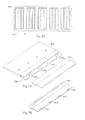
An array of devices (e.g. PV device “P”, spacer devices “S”, edge pieces “E”, etc.) function to provide electrical energy when subjected to solar radiation (e.g. sunlight). An array is a collection of interconnected devices as installed on a building structure 1100. For the purposes of this invention, it is contemplated that the array 1000 is installed directly on an existing roof structure (or exterior surface) of a building structure 1100, over a roofing underlayment material (felt, self-adhered water barrier, fire-retardant layer, or moisture barrier sheet), or over a previously installed roofing material (e.g. asphalt shingles), in the same way traditional roofing elements are applied (unless otherwise noted herein). In a preferred embodiment, these arrays 1000 may be made up of two or more rows of adjoining devices, the rows containing at least two or more devices themselves. One or more interface members 500, described in more detail below, may be disposed on the bottom of the array 1000. As an illustrative example, at least partially shown in FIG. 3A, the array 1000 presented has 6 rows, multiple devices per row including an edge piece on each end and one exemplary illustration of interface members 500 making up the bottom row of the array (row 6). The focus of this invention is how an interface member or members 500 may help resolve one or more of the problems discussed in this application.
Interface Members 500
An interface member 500 functions to provide an interface row between the PV sheathing devices 100 and any non-PV sheathing device cladding materials (e.g. traditional asphalt shingles, premium roofing material such as concrete tile or natural slate, or similar components, herein referred to as a “sheathing member” 600). The member or members 500 may provide a nesting portion for both the PV sheathing devices 100 and for the sheathing member 600. It is contemplated that the member may allow for the installation/removal of devices 100 and/or members 600 independently of each other and in any order.
It is contemplated that the interface member 500 may at least be a three dimensional component that includes a PV sheathing element nesting portion 510 and a building sheathing nesting portion 520. Exemplary embodiments and variations are discussed in detail below. The PV sheathing element nesting portion 510 functions as a receiving area for the devices 100, wherein typically the device sits on top of the nesting portion in the installed position. It is contemplated that the nesting portion may include positioning features that aid in locating the devices. The building sheathing nesting portion 520 functions as at least receiving area for the sheathing members 600, wherein the member 600 at least abuts the nesting portion, for example as shown in FIG. 4. It is also contemplated that the member 500 may include horizontal overlap portions 525, for example as shown in FIGS. 5A, B and C, which function to provide an interface/overlap area between the side of the member and horizontally adjoining sheathing members 600. FIGS. 5A, B and C also show a living hinge 532 for the member 500, a nesting portion 520, an integral upper flashing portion 530, a lower flashing portion 550 and a horizontal overlap portion 525. FIG. 5A is a side view. 5B is a view with dotted lines showing the location of the living hinge 532 not visible from this perspective. 5C is a perspective view where the side of the living hinge 532 is shown and the unseen path of the living hinge is shown by dotted lines. It is also contemplated that the member 500 may have a unique geometry when it is made to be used at or near the end of a row (e.g. in conjunction with device “E”, an edge piece), for example as shown in FIGS. 3B-D.
It is contemplated that the interface member 500 may be in the form of a discrete component (e.g. a panel-like member akin to devices 100) or may be in a continuous roll form, for example as shown in FIGS. 4 and 6 respectively.
In a preferred embodiment, the member 500 is constructed essentially of a polymeric material. Preferred materials or combinations of materials include a filled or unfilled moldable plastic (e.g. polyolefins, acrylonitrile butadiene styrene, hydrogenated styrene butadiene rubbers, polyesters, polyamides, polyester amides, polysulfone, acetal, acrylic, polyvinyl chloride, nylon, polyethylene terephthatate, polycarbonate, thermoplastic and thermoset polyurethanes, synthetic and natural rubbers, epoxies, styrene-acrylonitrile (“SAN”), polymethyl methacrylate, polystyrene, or any combination thereof). Fillers can include one or more of the following: colorants, fire retardant (“FR”) or ignition resistant (“IR”) materials, reinforcing materials, such as glass or mineral fibers, mineral fillers, such as talc, calcium carbonate or mica, or surface modifiers. Plastic can also include anti-oxidants, release agents, blowing agents, and other common plastic additives.
In the case where the member 500 is in a continuous roll form, for example as shown in FIGS. 6A-C, the preferred materials include: Polyolefins; hydrogenated styrene butadiene rubber; polyesters; polyamides: polyesteramides; poly (vinyl chloride); synthetic and natural rubbers; EPDM; and asphalt type compounds (i.e., shingle like material). A preferred embodiment can also be further defined as wherein X=(thickness in mm)^2/(ultimate strain in percent), X is about 200 or less, more preferably about 50 or less, most preferably about 10 or less and/or wherein Y=(Modulus of elasticity in MPa* thickness in mm), Y is less than about 20,000, more preferably about 4,000 or less, most preferably about 1,000 or less. Alternately, much higher ratios may be used when the thickness of the roll-out material is not uniform, for example as shown in FIGS. 6B-C, by having localized thin regions (region “F”). The materials may also include anti-oxidants, release agents, blowing agents, and other common additives used in plastic materials.
In a first embodiment, for example as shown in FIGS. 4 and 6, the member 500 may also include an integral upper flashing portion 530. The integral upper flashing portion 530 functions to cover a portion of the sheathing member 600, preferably covering at least down to and past the area which the sheathing member is secured to the building structure (e.g. where it is nailed to the roof). The portion 530 may be part of or separate to the building sheathing nesting portion 520. In a preferred embodiment, the integral upper flashing portion 530 is sufficiently flexible to allow the installation/removal of sheathing members 600 underneath it when installed on the building structure. It is contemplated that this “flexibility” may be obtained in any number of ways, including but not limited to: selecting a flexible material, adding geometric features such as a living hinge 532, or both. In a preferred embodiment, the upper flashing has a length (FL) of about 10 mm or greater, more preferably about 50 mm or greater, and most preferably about 100 mm or greater. This length is functionally so as to cover fasteners and/or edge tolerances on roofing material that is covered by the upper flashing 530.
In a second embodiment, for example as shown in FIG. 7, the member may also include a removable upper flashing portion 540 (e.g. a two piece system). The removable upper flashing portion 540 functions to cover a portion of the sheathing member 600, preferably covering at least down to and past the area which the sheathing member is secured to the building structure (e.g. where it is nailed to the roof). The portion 540 may be part of or separate to the building sheathing nesting portion 520. In a preferred embodiment, the portion 540 may include retention features 542 that allow this removable piece to be secured to the interface member 500. It is contemplated that the retention features may be in the form of snaps, hooks, hook/loop fasteners, adhesives, or by any means appropriate to enable the desired function. It is contemplated that appropriate mating features are disposed in the interface member. One example may be seen in FIG. 7. It is also contemplated that it may be desirable to include an additional securing mechanism at or near (e.g. within about 25 mm) to the bottom edge of the portion 540. As illustrated in FIG. 7 in the middle section, in one preferred method, a zone of adhesive 544 may be utilized to provide the additional securing mechanism (see below in the fifth embodiment for preferred adhesives that may be utilized).
In a third embodiment, for example as shown in FIG. 7, the interface member 500 may include a lower flashing portion 550, generally in conjunction with the building sheathing nesting portion 520. This lower flashing functions to provide an additional barrier between the building structure and the sheathing member 600 and also may provide for additional securing areas for the interface member 500. As illustrated in FIGS. 7, 8, and 9 the lower flashing portion 550 may include fastener holes 552 (e.g. for receiving fasteners, such as nails or screws) and retention features 554 adapted to mate with corresponding retention features 542 of an upper flashing portion 540. It is also contemplated that the lower flashing portion 550 has a relatively small thickness. Preferably it has a thickness of about 15 mm or less. In one preferred embodiment, the thickness may be is about 0.01 mm or greater, more preferably about 1.5 mm or greater, and most preferably is about 3.0 mm or greater, and the thickness is about 15.0 mm or less, more preferably about 10.0 mm or less, and most preferably at most about 5.0 mm or less. It is also contemplated that the lower flashing portion 550 have a certain length (LFL, as best shown in FIG. 10). In one preferred embodiment, the length may be is at about 10 mm or greater, more preferably about 15 mm or greater, and most preferably is about 25 mm or greater, and the length is about 500 mm or less, more preferably about 350 mm or less, and most preferably about 200 mm or less.
In a fourth embodiment, for example as shown in FIGS. 8A-B, the interface member 500 may include one or more PV device retention features 560. These features 560 may function to aid in the securing of and hold-down strength of the PV devices 100, particularly against the forces of wind up-lift (e.g. winds hitting the devices 100 normal to the forward edge at speeds of about 50 Km/hr or more). It is contemplated that those features 560 can be simple holes or depressions in the interface member 500 that is adapted to receive separate fasteners (e.g. clips as shown in FIG. 8B), can be integrally formed fasteners (e.g. hook-like structures as shown in FIG. 8A), can be secondary components, or can be a zone of adhesive that may be disposed on the member (preferably a pressure sensitive adhesive).
In a fifth embodiment, for example as shown in FIG. 9, the interface member 500 may include one or more sheathing member retention features 570. It may be preferred that any retention feature used in this area should not create additional holes in the building structure and have a relatively thin profile or thickness (e.g. about 0.01 mm to 4 mm). In the most preferred embodiment of the sheathing member retention features 570, a zone of adhesive is provided between the lower flashing portion 550 and the element 600 that provides the feature 570.
In general, it is preferred that the retention features 570 comprises a adhesive that maintains a minimum peel force of about 3 PLI (pounds per linear inch), more preferably about 5 PLI, and most preferred about 10 PLI or more, per ASTM D 903-98 at temperatures between about −40° C. and about 85° C. and have an elongation of about 500% or greater, more preferably about 1000% or greater per ASTM D 412-06. It is also preferred if the adhesive maintains a thickness (after assembly) of about 0.5 mm or more, more preferably from about 0.7 mm to about 2.0 mm.
In one preferred embodiment, the retention feature 570 is comprised of a pressure sensitive adhesive (PSA) or a contact adhesive, that bonds to surfaces on contact (no curing time required) and to the respective surfaces (e.g. adjoining device 10, or structure or an asphalt shingle) with very slight pressure. They may be available in solvent and latex or water based forms. It is believed that pressure sensitive adhesives and contact adhesives are often based on non-crosslinked rubber adhesives, acrylics or polyurethanes. It is also believed that pressure sensitive adhesives form viscoelastic bonds that are aggressively and permanently tacky; adhere without the need of more than a finger or hand pressure; and require no activation by water, solvent or heat.
Pressure sensitive adhesives and contact adhesives may be available in a wide variety of chemical compositions or systems. Some contemplated PSAs include acrylic and methacrylate adhesives, rubber-based pressure sensitive adhesives, alkadiene styrene copolymers (SIS/SBS) and hydrogenated versions thereof, and silicones. Acrylic adhesives are known for excellent environmental resistance and fast-setting time when compared with other resin systems. Acrylic pressure sensitive adhesives often use an acrylate system. Ethylene ethyl acrylate (EEA) or ethylene methyl acrylate (EMA) copolymers are used to form hot melt PSA adhesives. Natural rubber, synthetic rubber or elastomer sealants and adhesives can be based on a variety of systems such silicone, polyurethane, chloroprene, butyl, polybutadiene, isoprene or neoprene. In a preferred embodiment, the PSA include Ethylene Propylene Copolymer Tape, rubber based adhesives, synthetic rubber-based tape, PE foam tape, and acrylic based and or combination of the above in multi layer construction, e.g., Acrylic/PET/Acrytic. The most preferred adhesive being a butyl adhesive tape. It is contemplated that some important characteristics of the adhesive include adhesives with instant aggressive adhesion/tack to the roofing structure without the use of secondary materials such as primers, yet also has and retains high strength at and after weather extremes (such as elevated temperatures, e.g., 85° C., for prolonged periods, and provides watertight attachment of components to roofing structure. Some examples of commercially available (and trademarked) adhesives may include: Butyl, Ashland Plioseal Seam tape, Adco PVA series (e.g., PVA 600BT and 650BT); Rubber based Adco SP-505 Cured Roofing Seam Tape; Synthetic rubber based: MACtac TM1039 and GS series; Ethylene propylene copolymer: SikaLastomer 68; Acrylic/PET/Acrylic; and Tesa Tape 4965 PET reinforced; and PE Foam Tape; Tesa Tape 62932 D/C Foam Tape.
In a sixth embodiment, for example as shown in FIGS. 10 and 11, the interface member 500 may include one or more features that function as a snow/ice guard 580. Such guards 580 function to aid in preventing relatively large snow and/or ice sheets from sliding off of the array 1000, either entirely sliding off or at least as a large sheet (e.g. breaking up the sheet as it moves past the guard 580), or may be a heating element that prevents the formation of the snow/ice on the member 500. It is contemplated that in one embodiment, the guard 580 may be a simple projection that projects above the plane of the device 100 and is capable of holding back snow/ice sheets or can aid in the break-up of the sheets as they slide past the member 500. In one preferred configuration, as shown in FIG. 10, the guard 580 is a wedge shaped projection that is configured to split any snow/ice sheets that move past it. In another preferred configuration, the guard 580 comprises resistive heating elements that are disposed within or on the surface of the member 500 and help to maintain the surface temperature of the member (at least in localized areas) above freezing.
Method
It is contemplated in the present invention that the installation method provide herein is unique and aids in resolving one or more of the issues identified earlier in the application. It is contemplated that the array of devices 1000 may be installed before or after the installation of the other sheathing members 600 and vice versa, all because of the use of the interface members 500. It is contemplated that the interface member, at least in some embodiments, can be installed after the sheathing members 600 are installed.
It is contemplated that method of constructing a photovoltaic device assembly on a surface of a structure 1100, may comprise the steps of: a. providing a plurality of individual photovoltaic devices 100, wherein the individual photovoltaic devices include: i. a body portion including lower surface portion that contacts the structure, and an upper surface portion that receives a fastener (one or more) that attaches the photovoltaic device to the structure; b. providing one or more interface members as applied to the structure, disposed under a portion of the photovoltaic devices, the interface members including a photovoltaic device nesting portion and a building sheathing nesting portion; c. placing and attaching one or more interface members to the surface; d. placing a first individual photovoltaic device on to the one or more interface members in the photovoltaic device nesting portion; e. attaching a first individual photovoltaic device to the one or more interface members and to the structure; f. repeat steps c-e until a first row of photovoltaic devices is attached to the surface.
It is also contemplated that the steps of providing a sheathing member, placing the sheathing member into the building sheathing nesting portion, and attaching the sheathing member to the structure may be included in the inventive method. These steps may come anywhere after step “c”. Also, as stated before, the interface member, at least in some embodiments, can be installed after the sheathing members 600 are installed. It is also contemplated that step “c” may only have to be completed one time, for example in the case of a rolled out interface member (e.g. see FIG. 6) or if more than one interface member is installed before any other components are installed.
It is contemplated and expressly stated herein that the embodiments or examples described above may not be mutually exclusive and may be used in combination with each other.
Unless stated otherwise, dimensions and geometries of the various structures depicted herein are not intended to be restrictive of the invention, and other dimensions or geometries are possible. Plural structural components can be provided by a single integrated structure. Alternatively, a single integrated structure might be divided into separate plural components. In addition, while a feature of the present invention may have been described in the context of only one of the illustrated embodiments, such feature may be combined with one or more other features or other embodiments, for any given application. It will also be appreciated from the above that the fabrication of the unique structures herein and the operation thereof also constitute methods in accordance with the present invention.
The preferred embodiment of the present invention has been disclosed. A person of ordinary skill in the art would realize however, that certain modifications would come within the teachings of this invention. Therefore, the following claims should be studied to determine the true scope and content of the invention.
Any numerical values recited in the above application include all values from the lower value to the upper value in increments of one unit provided that there is a separation of at least 2 units between any lower value and any higher value. As an example, if it is stated that the amount of a component or a value of a process variable such as, for example, temperature, pressure, time and the like is, for example, from 1 to 90, preferably from 20 to 80, more preferably from 30 to 70, it is intended that values such as 15 to 85, 22 to 68; 43 to 51, 30 to 32 etc. are expressly enumerated in this specification. For values which are less than one, one unit is considered to be 0.0001, 0.001, 0.01 or 0.1 as appropriate. These are only examples of what is specifically intended and all possible combinations of numerical values between the lowest value and the highest value enumerated are to be considered to be expressly stated in this application in a similar manner.
Unless otherwise stated, all ranges include both endpoints and all numbers between the endpoints. The use of “about” or “approximately” in connection with a range applies to both ends of the range. Thus, “about 20 to 30” is intended to cover “about 20 to about 30”, inclusive of at least the specified endpoints.
The disclosures of all articles and references, including patent applications and publications, are incorporated by reference for all purposes.
The term “consisting essentially of” to describe a combination shall include the elements, ingredients, components or steps identified, and such other elements ingredients, components or steps that do not materially affect the basic and novel characteristics of the combination.
The use of the terms “comprising” or “including” describing combinations of elements, ingredients, components or steps herein also contemplates embodiments that consist essentially of the elements, ingredients, components or steps.
Plural elements, ingredients, components or steps can be provided by a single integrated element, ingredient, component or step. Alternatively, a single integrated element, ingredient, component or step might be divided into separate plural elements, ingredients, components or steps. The disclosure of “a” or “one” to describe an element, ingredient, component or step is not intended to foreclose additional elements, ingredients, components or steps. All references herein to elements or metals belonging to a certain Group refer to the Periodic Table of the Elements published and copyrighted by CRC Press, Inc., 1989. Any reference to the Group or Groups shall be to the Group or Groups as reflected in this Periodic Table of the Elements using the IUPAC system for numbering groups.

Claims (16)

What is claimed is:
1. A method of constructing a building-integrated photovoltaic device assembly on a surface of a structure, comprising the steps of:
a. providing a plurality of photovoltaic (PV) sheathing elements, adapted to serve as an outer cladding of a structure, in one or more rows or columns as applied to the structure so that the plurality of photovoltaic sheathing elements when attached together form the building-integrated photovoltaic device assembly, which includes a bottom edge, and each of the PV sheathing elements including:
i. a body portion including:
1. a lower surface portion that directly contacts the structure and
2. an upper surface portion that receives one or more fasteners that attaches each of the PV sheathing elements to the structure;
b. providing one or more interface members as applied to the structure, disposed under a portion of the bottom edge of the building-integrated photovoltaic device assembly, the one or more interface members including:
1. an photovoltaic device nesting portion,
2. a building sheathing nesting portion, and
3. one or more photovoltaic device retention features;
c. placing and attaching the one or more interface members directly to the surface so that the one or more interface members form an interface row between the bottom edge of the building-integrated photovoltaic device assembly and a row of sheathing members;
d. placing a first individual PV sheathing element of the plurality of PV sheathing elements in the first row of the PV sheathing elements on to the one or more interface members in the photovoltaic device nesting portion;
e. attaching the first individual PV sheathing element to the one or more interface members with the one or more photovoltaic device retention features, and attaching the first individual PV sheathing element to the structure with one or more fasteners that extend through the upper surface portion;
f. repeating steps c-e or d-e until the first row or the first column of PV sheathing elements are attached to the surface; and
g. attaching a plurality of individual PV sheathing element in a second row and creating an overlap by placing the second row so that the second row covers a portion of each of the individual PV sheathing elements in the first row; and
wherein the one or more retention features are a plurality of retention features that each have a generally “C” shaped hook structure.
2. The method according to claim 1, including the steps of providing the sheathing members, placing the sheathing member into the building sheathing nesting portion, and attaching the sheathing members to the structure.
3. The method according to claim 1, wherein the one or more interface members include an upper flashing portion that covers a portion of a building sheathing member and the upper flashing portion comprises a flexible ledge portion disposed forward of the photovoltaic device nesting portion and above the building sheathing nesting portion.
4. The method according to claim 1, wherein the one or more interface members comprise a flexible sheet that can be rolled out as applied to the structure.
5. The method according to claim 3, wherein the upper flashing portion comprises a removable flashing member.
6. The method according to claim 1, wherein the one or more interface members include an upper flashing portion and a lower flashing portion that are two discrete pieces, and the one or more photovoltaic device retention features are located on the upper flashing portion and the lower flashing portion and the retention features on the lower flashing portion are adapted to mate with the retention features of the upper flashing portion.
7. The method according to claim 1, wherein the interface members include one or more features that are a snow guard, an ice guard, or both.
8. The method according to claim 1, wherein the retention features comprise a mechanical fastening device, an adhesive, or both that connect the PV sheathing elements to the one or more interface members.
9. The method according to claim 6, wherein the retention features comprise a mechanical fastening device, an adhesive, or both that connect the PV sheathing elements to the one or more interface members.
10. The method according claim 3, wherein the upper flashing portion has a sufficient length to cover fasteners disposed on the sheathing member.
11. The method according to claim 1, wherein the one or more interface members include a second set of retention features that are located between each of the generally “C” shaped hook structures.
12. The method according to claim 1, wherein the one or more retention features are located at a forward edge of the one or more interface members so that the one or more retention features are located at the bottom edge of the building-integrated photovoltaic device assembly and assist in holding down a bottom edge of each of the PV sheathing elements against forces of wind up-lift.
13. The method according to claim 1, wherein the one or more photovoltaic retention features connect to the PV sheathing elements without creating additional holes in the structure.
14. The method according to claim 11, wherein the one or more retention features are located at a forward edge of the one or more interface members so that the one or more retention features are located at the bottom edge of the building-integrated photovoltaic device assembly and assist in holding down a bottom edge of each of the PV sheathing elements against forces of wind up-lift, and the one or more photovoltaic retention features connect to the PV sheathing elements without creating additional holes in the structure.
15. The method according to claim 1, wherein the one or more photovoltaic device retention features are an adhesive with a minimum peel force of about 5 pounds per linear inch measured using ASTM D 903-98 at a temperature between about −40° C. and about 85° C.
16. The method according to claim 1, wherein the one or more photovoltaic device retention features are an adhesive that has an elongation of about 500% or greater when measured using ASTM D 421-06, and the adhesive has a thickness after assembly from about 0.7 mm to about 2.0 mm.
US14/234,211 2011-07-29 2012-07-27 Interface system and method for photovoltaic cladding to standard cladding Active 2032-09-09 US9537033B2 (en)

Priority Applications (1)

Application Number Priority Date Filing Date Title
US14/234,211 US9537033B2 (en) 2011-07-29 2012-07-27 Interface system and method for photovoltaic cladding to standard cladding

Applications Claiming Priority (3)

Application Number Priority Date Filing Date Title
US201161513268P 2011-07-29 2011-07-29
PCT/US2012/048571 WO2013019628A1 (en) 2011-07-29 2012-07-27 Interface system and method for photovoltaic cladding to standard cladding
US14/234,211 US9537033B2 (en) 2011-07-29 2012-07-27 Interface system and method for photovoltaic cladding to standard cladding

Publications (2)

Publication Number Publication Date
US20150083197A1 US20150083197A1 (en) 2015-03-26
US9537033B2 true US9537033B2 (en) 2017-01-03

Family

ID=47629614

Family Applications (1)

Application Number Title Priority Date Filing Date
US14/234,211 Active 2032-09-09 US9537033B2 (en) 2011-07-29 2012-07-27 Interface system and method for photovoltaic cladding to standard cladding

Country Status (6)

Country Link
US (1) US9537033B2 (en)
EP (1) EP2737548A1 (en)
JP (1) JP2014524999A (en)
CN (1) CN104145421B (en)
BR (1) BR112014002176A2 (en)
WO (1) WO2013019628A1 (en)

Cited By (1)

* Cited by examiner, † Cited by third party
Publication number Priority date Publication date Assignee Title
US10693413B2 (en) 2017-10-19 2020-06-23 Building Materials Investment Corporation Roof integrated photovoltaic system

Families Citing this family (12)

* Cited by examiner, † Cited by third party
Publication number Priority date Publication date Assignee Title
US10256765B2 (en) 2013-06-13 2019-04-09 Building Materials Investment Corporation Roof integrated photovoltaic system
US9273885B2 (en) * 2013-06-13 2016-03-01 Building Materials Investment Corporation Roof integrated photovoltaic system
WO2017014960A1 (en) 2015-07-20 2017-01-26 Dow Global Technologies Llc Installation indicators for a photovoltaic roofing system and a method of forming a photovoltaic roofing system
US20180219512A1 (en) 2015-07-20 2018-08-02 Dow Global Technologies Llc Irregular photovoltaic roofing system with a flashing piece
US20180212565A1 (en) 2015-07-20 2018-07-26 Dow Global Technologies Llc Alignment features for a photovoltaic roofing system and a method of forming a photovoltaic roofing system
WO2017014942A1 (en) 2015-07-20 2017-01-26 Dow Global Technologies Llc Water tight photovoltaic roofing system
US10560048B2 (en) * 2015-11-02 2020-02-11 Certainteed Corporation Photovoltaic roofing systems with bottom flashings
WO2018044856A1 (en) * 2016-09-02 2018-03-08 Dow Global Technologies Llc Base plate including a support structure for reducing stepping loads on a photovoltaic laminate
CN111295835B (en) * 2017-03-14 2021-07-13 分水岭太阳能有限责任公司 Solar energy system for use with tufted geosynthetics
GB201905849D0 (en) * 2019-04-26 2019-06-12 Roof Tiles Tech Limited Photovoltaic roof covering and method of manufacture
WO2021202327A1 (en) 2020-03-30 2021-10-07 Building Materials Investment Corporation Interlocking laminated structural roofing panels
MX2021013676A (en) 2020-11-09 2022-05-10 Bmic Llc Interlocking structural roofing panels with integrated solar panels.

Citations (62)

* Cited by examiner, † Cited by third party
Publication number Priority date Publication date Assignee Title
US2631887A (en) 1951-12-01 1953-03-17 Gen Motors Corp Hinged finish molding for vehicle closures
US3234701A (en) * 1963-05-31 1966-02-15 Ivan M Burtch Asphalt shingle roof and method of sealing
US3767471A (en) 1971-09-01 1973-10-23 Bell Telephone Labor Inc Group i-iii-vi semiconductors
JPS56169020U (en) 1980-05-19 1981-12-14
US4465575A (en) 1981-09-21 1984-08-14 Atlantic Richfield Company Method for forming photovoltaic cells employing multinary semiconductor films
US4586301A (en) 1984-08-06 1986-05-06 W. P. Hickman Company Retainer clamp membrane fastening system
US4627207A (en) 1978-03-02 1986-12-09 W. R. Grace & Co. Fastener for securing roofing material to cementitious roof decks having removable tab
US4641471A (en) 1978-03-02 1987-02-10 W. R. Grace & Co. Fastener for securing roofing material to cementitious roof decks
US4641472A (en) 1978-03-02 1987-02-10 W. R. Grace & Co. Fastener for securing roofing material to cementitious roof decks having removable tab
US4652321A (en) * 1985-07-10 1987-03-24 Duro-Last Roofing Inc. Methods of forming polymer coated fabric roof vent pipe enclosures in flexible roof covering membranes
US4686808A (en) 1983-03-14 1987-08-18 John D. Gray Roofing system, method and holddown apparatus
JPH02143468A (en) 1988-11-24 1990-06-01 Mitsubishi Electric Corp Solar cell
JPH02216874A (en) 1989-02-17 1990-08-29 Hitachi Ltd Silicon crystalline solar cell
JPH053430U (en) 1991-06-26 1993-01-19 株式会社クボタ Power generation roof tile
US5239802A (en) 1990-08-13 1993-08-31 Certainteed Corporation Adhesive arrangement for shingles and the like
EP0841706A2 (en) 1996-11-08 1998-05-13 Showa Shell Sekiyu Kabushiki Kaisha Transparent conductive film of thin-film solar cell and method for producing the transparent conductive film
JPH10189924A (en) 1996-12-27 1998-07-21 Canon Inc Production of semiconductor basic material and solar cell
JPH10212805A (en) 1997-12-05 1998-08-11 Canon Inc Building material with solar cell
JPH10231590A (en) 1997-02-21 1998-09-02 Matsushita Electric Works Ltd Roof tile fixture and roof tile fixing structure using roof tile fixture
US5950387A (en) 1998-05-11 1999-09-14 Certainteed Corporation Wind-resistant shingle and method of applying
JPH11303323A (en) 1998-04-27 1999-11-02 Sekisui Chem Co Ltd Roof tile fixing structure
JP2000501469A (en) 1996-09-23 2000-02-08 アトランテイス ソーラー システム アクチエンゲゼルシヤフト Photovoltaic solar roof
WO2000030184A1 (en) 1998-11-13 2000-05-25 Us Solar Roof Photovoltaic roof tile
EP1032051A2 (en) 1999-02-26 2000-08-30 Kaneka Corporation Method for manufacturing thin film photovoltaic device
US6148570A (en) 1998-02-05 2000-11-21 Powerlight Corporation Photovoltaic building assembly with continuous insulation layer
JP2001098703A (en) 1999-07-23 2001-04-10 Kanegafuchi Chem Ind Co Ltd Roof structure and roofing method
US6247289B1 (en) 1999-10-26 2001-06-19 Walter R. Karpinia Roof shingle reinforcing strap
JP2001227109A (en) 2000-02-21 2001-08-24 Misawa Homes Co Ltd Solar cell tiles
JP2001279871A (en) 2000-01-28 2001-10-10 Toru Ishikawa Method for fixing roof tile and tile fixing member used in the same
US20020066235A1 (en) 2000-07-03 2002-06-06 Stearns Brian C. Roof mount
JP2003147913A (en) 1996-05-10 2003-05-21 Sekisui Chem Co Ltd Roof structure and manufacturing method therefor
JP2003179246A (en) 2001-12-12 2003-06-27 Sony Corp Photo generator, its attachment and electric or electronic apparatus
US20030154680A1 (en) 2002-02-20 2003-08-21 Dinwoodie Thomas L. Shingle assembly
US20030188500A1 (en) 2002-04-05 2003-10-09 Voegele William P. Panel clip assembly for use with skylight or roof panels
US6725623B1 (en) 2000-11-15 2004-04-27 Action Manufacturing, Llc Standing seam metal roof wind uplift prevention bar
US20040083673A1 (en) 2002-11-06 2004-05-06 Kalkanoglu Husnu M. Shingle with improved blow-off resistance
EP1431476A1 (en) 2001-09-28 2004-06-23 Kaneka Corporation Solar battery module, method of laying solar battery module, and blowout prevention device for solar battery module
US20040206035A1 (en) 2003-04-17 2004-10-21 Emco Building Products Limited Roofing shingle with headlap seal and improved coverage
US20040216405A1 (en) 2003-05-01 2004-11-04 Henry Gembala Fastener for lightweight concrete roof systems
US20050011550A1 (en) 2002-01-25 2005-01-20 Chittibabu Kethinni G. Low temperature interconnection of nanoparticles
US20050229924A1 (en) 2004-03-30 2005-10-20 Luconi Gregg F Self-ballasting solar collector
USRE38988E1 (en) 1996-04-08 2006-02-28 Dinwoodie Thomas L Lightweight, self-ballasting photovoltaic roofing assembly
DE102005061709A1 (en) 2004-12-21 2007-03-15 Heisterkamp, Norbert, Dr.-Ing. Solar roof structure for solar energy has a sheet with trapezoidal corrugations, flutes and valleys as well as support padding to relieve pressure and absorb vibration
WO2007035677A2 (en) 2005-09-19 2007-03-29 Solar Roofing Systems, Inc. Integrated solar roofing system
WO2007079382A2 (en) 2005-12-28 2007-07-12 Sunpower Corporation, Systems Supported pv module assembly
US20070193135A1 (en) 2006-02-01 2007-08-23 Vandenberg Charles J Aerodynamic roof lift-prevention device
US20070199590A1 (en) * 2004-04-14 2007-08-30 Masao Tanaka Roof Tile-Integrated Solar Battery Module
JP2007243166A (en) 2006-02-08 2007-09-20 Ntt Facilities Inc Electric power generating system for roof
WO2007123927A2 (en) 2007-04-17 2007-11-01 Deliddo Jack P Apparatus and method for attaching solar panels to roof system surfaces
US20070256734A1 (en) 2006-05-08 2007-11-08 United Solar Ovonic Llc Stabilized photovoltaic device and methods for its manufacture
US20070295391A1 (en) 2006-03-09 2007-12-27 Sunpower Corporation PV Module Mounting and Support Assembly and Installation
US20080083169A1 (en) 2006-10-10 2008-04-10 Sicurella Daniel J Structural wind protective system and method
WO2008063660A2 (en) 2006-11-21 2008-05-29 Firestone Building Products Company, Llc Hook and loop attachment of solar panels to roofing membranes
US20080196231A1 (en) 2007-02-20 2008-08-21 David Grove Interlocking continuous roof assembly method for wind resistant roofing
US20080196358A1 (en) 2004-05-11 2008-08-21 Holger Schwedler System and Assembly for Sealing Containers
US20080245399A1 (en) 2007-04-05 2008-10-09 Deliddo Jack P Apparatus and method for attaching solar panels to roof system surfaces
US20080245404A1 (en) 2007-04-05 2008-10-09 Deliddo Jack P Apparatus and method for attaching solar panels to roof system surfaces
FR2914785A1 (en) 2007-04-06 2008-10-10 Saint Gobain Ct Recherches PHOTOVOLTAIC ROOF COATING
US20080302031A1 (en) 2007-06-05 2008-12-11 Solar Roofing Systems, Inc., Integrated solar roofing tile connection system
WO2009137352A2 (en) 2008-05-05 2009-11-12 Dow Global Technologies Inc. System for installation of photovoltaic devices on a structure
US20100242381A1 (en) * 2009-03-24 2010-09-30 Jenkins Robert L Photovoltaic systems, methods for installing photovoltaic systems, and kits for installing photovoltaic systems
US8215071B2 (en) * 2010-02-02 2012-07-10 Sunpower Corporation Integrated composition shingle PV system

Patent Citations (78)

* Cited by examiner, † Cited by third party
Publication number Priority date Publication date Assignee Title
US2631887A (en) 1951-12-01 1953-03-17 Gen Motors Corp Hinged finish molding for vehicle closures
US3234701A (en) * 1963-05-31 1966-02-15 Ivan M Burtch Asphalt shingle roof and method of sealing
US3767471A (en) 1971-09-01 1973-10-23 Bell Telephone Labor Inc Group i-iii-vi semiconductors
US4627207A (en) 1978-03-02 1986-12-09 W. R. Grace & Co. Fastener for securing roofing material to cementitious roof decks having removable tab
US4641471A (en) 1978-03-02 1987-02-10 W. R. Grace & Co. Fastener for securing roofing material to cementitious roof decks
US4641472A (en) 1978-03-02 1987-02-10 W. R. Grace & Co. Fastener for securing roofing material to cementitious roof decks having removable tab
JPS56169020U (en) 1980-05-19 1981-12-14
US4465575A (en) 1981-09-21 1984-08-14 Atlantic Richfield Company Method for forming photovoltaic cells employing multinary semiconductor films
US4686808A (en) 1983-03-14 1987-08-18 John D. Gray Roofing system, method and holddown apparatus
US4586301A (en) 1984-08-06 1986-05-06 W. P. Hickman Company Retainer clamp membrane fastening system
US4652321A (en) * 1985-07-10 1987-03-24 Duro-Last Roofing Inc. Methods of forming polymer coated fabric roof vent pipe enclosures in flexible roof covering membranes
JPH02143468A (en) 1988-11-24 1990-06-01 Mitsubishi Electric Corp Solar cell
JPH02216874A (en) 1989-02-17 1990-08-29 Hitachi Ltd Silicon crystalline solar cell
US5239802A (en) 1990-08-13 1993-08-31 Certainteed Corporation Adhesive arrangement for shingles and the like
JPH053430U (en) 1991-06-26 1993-01-19 株式会社クボタ Power generation roof tile
USRE38988E1 (en) 1996-04-08 2006-02-28 Dinwoodie Thomas L Lightweight, self-ballasting photovoltaic roofing assembly
JP2003147913A (en) 1996-05-10 2003-05-21 Sekisui Chem Co Ltd Roof structure and manufacturing method therefor
JP2000501469A (en) 1996-09-23 2000-02-08 アトランテイス ソーラー システム アクチエンゲゼルシヤフト Photovoltaic solar roof
EP0841706A2 (en) 1996-11-08 1998-05-13 Showa Shell Sekiyu Kabushiki Kaisha Transparent conductive film of thin-film solar cell and method for producing the transparent conductive film
JPH10189924A (en) 1996-12-27 1998-07-21 Canon Inc Production of semiconductor basic material and solar cell
JPH10231590A (en) 1997-02-21 1998-09-02 Matsushita Electric Works Ltd Roof tile fixture and roof tile fixing structure using roof tile fixture
JPH10212805A (en) 1997-12-05 1998-08-11 Canon Inc Building material with solar cell
US6148570A (en) 1998-02-05 2000-11-21 Powerlight Corporation Photovoltaic building assembly with continuous insulation layer
JPH11303323A (en) 1998-04-27 1999-11-02 Sekisui Chem Co Ltd Roof tile fixing structure
US5950387A (en) 1998-05-11 1999-09-14 Certainteed Corporation Wind-resistant shingle and method of applying
WO2000030184A1 (en) 1998-11-13 2000-05-25 Us Solar Roof Photovoltaic roof tile
EP1032051A2 (en) 1999-02-26 2000-08-30 Kaneka Corporation Method for manufacturing thin film photovoltaic device
JP2001098703A (en) 1999-07-23 2001-04-10 Kanegafuchi Chem Ind Co Ltd Roof structure and roofing method
US6247289B1 (en) 1999-10-26 2001-06-19 Walter R. Karpinia Roof shingle reinforcing strap
US6397556B1 (en) 1999-10-26 2002-06-04 Walter R. Karpinia Reinforced roof shingle
JP2001279871A (en) 2000-01-28 2001-10-10 Toru Ishikawa Method for fixing roof tile and tile fixing member used in the same
JP2001227109A (en) 2000-02-21 2001-08-24 Misawa Homes Co Ltd Solar cell tiles
US20020066235A1 (en) 2000-07-03 2002-06-06 Stearns Brian C. Roof mount
US6725623B1 (en) 2000-11-15 2004-04-27 Action Manufacturing, Llc Standing seam metal roof wind uplift prevention bar
EP1431476A1 (en) 2001-09-28 2004-06-23 Kaneka Corporation Solar battery module, method of laying solar battery module, and blowout prevention device for solar battery module
JP2003179246A (en) 2001-12-12 2003-06-27 Sony Corp Photo generator, its attachment and electric or electronic apparatus
US20050011550A1 (en) 2002-01-25 2005-01-20 Chittibabu Kethinni G. Low temperature interconnection of nanoparticles
WO2003071047A2 (en) 2002-02-20 2003-08-28 Powerlight Corporation Shingle assembly
US20030154680A1 (en) 2002-02-20 2003-08-21 Dinwoodie Thomas L. Shingle assembly
US7178295B2 (en) 2002-02-20 2007-02-20 Powerlight Corporation Shingle assembly
US20030188500A1 (en) 2002-04-05 2003-10-09 Voegele William P. Panel clip assembly for use with skylight or roof panels
US6845592B2 (en) 2002-04-05 2005-01-25 Extech Exterior Technologies, Inc. Panel clip assembly for use with skylight or roof panels
US20040083673A1 (en) 2002-11-06 2004-05-06 Kalkanoglu Husnu M. Shingle with improved blow-off resistance
US7118794B2 (en) 2002-11-06 2006-10-10 Certainteed Corporation Shingle with improved blow-off resistance
US6758019B2 (en) 2002-11-06 2004-07-06 Certainteed Corporation Shingle with improved blow-off resistance
US20040206035A1 (en) 2003-04-17 2004-10-21 Emco Building Products Limited Roofing shingle with headlap seal and improved coverage
US7204063B2 (en) 2003-04-17 2007-04-17 EMCO Building Products Corp. Roofing shingle with headlap seal and improved coverage
US7299598B2 (en) 2003-05-01 2007-11-27 Henry Gembala Fastener for lightweight concrete roof systems
US20040216405A1 (en) 2003-05-01 2004-11-04 Henry Gembala Fastener for lightweight concrete roof systems
US20050229924A1 (en) 2004-03-30 2005-10-20 Luconi Gregg F Self-ballasting solar collector
US20070199590A1 (en) * 2004-04-14 2007-08-30 Masao Tanaka Roof Tile-Integrated Solar Battery Module
US20080196358A1 (en) 2004-05-11 2008-08-21 Holger Schwedler System and Assembly for Sealing Containers
DE102005061709A1 (en) 2004-12-21 2007-03-15 Heisterkamp, Norbert, Dr.-Ing. Solar roof structure for solar energy has a sheet with trapezoidal corrugations, flutes and valleys as well as support padding to relieve pressure and absorb vibration
WO2007035677A2 (en) 2005-09-19 2007-03-29 Solar Roofing Systems, Inc. Integrated solar roofing system
WO2007079382A2 (en) 2005-12-28 2007-07-12 Sunpower Corporation, Systems Supported pv module assembly
US20070193135A1 (en) 2006-02-01 2007-08-23 Vandenberg Charles J Aerodynamic roof lift-prevention device
JP2007243166A (en) 2006-02-08 2007-09-20 Ntt Facilities Inc Electric power generating system for roof
US20080000173A1 (en) 2006-03-09 2008-01-03 Sunpower Corporation PV Module Mounting Method and Mounting Assembly
US20090000220A1 (en) 2006-03-09 2009-01-01 Sunpower Corporation Photovoltaic module mounting clip with integral grounding
US20070295391A1 (en) 2006-03-09 2007-12-27 Sunpower Corporation PV Module Mounting and Support Assembly and Installation
US20070256734A1 (en) 2006-05-08 2007-11-08 United Solar Ovonic Llc Stabilized photovoltaic device and methods for its manufacture
US20080083169A1 (en) 2006-10-10 2008-04-10 Sicurella Daniel J Structural wind protective system and method
WO2008063660A2 (en) 2006-11-21 2008-05-29 Firestone Building Products Company, Llc Hook and loop attachment of solar panels to roofing membranes
US20080196231A1 (en) 2007-02-20 2008-08-21 David Grove Interlocking continuous roof assembly method for wind resistant roofing
US20080245399A1 (en) 2007-04-05 2008-10-09 Deliddo Jack P Apparatus and method for attaching solar panels to roof system surfaces
US20080245404A1 (en) 2007-04-05 2008-10-09 Deliddo Jack P Apparatus and method for attaching solar panels to roof system surfaces
US20100180523A1 (en) 2007-04-06 2010-07-22 Certainteed Corporation Photovoltaic Roof Covering
FR2914785A1 (en) 2007-04-06 2008-10-10 Saint Gobain Ct Recherches PHOTOVOLTAIC ROOF COATING
WO2007123927A2 (en) 2007-04-17 2007-11-01 Deliddo Jack P Apparatus and method for attaching solar panels to roof system surfaces
US20080302031A1 (en) 2007-06-05 2008-12-11 Solar Roofing Systems, Inc., Integrated solar roofing tile connection system
WO2009137352A2 (en) 2008-05-05 2009-11-12 Dow Global Technologies Inc. System for installation of photovoltaic devices on a structure
WO2009137353A2 (en) 2008-05-05 2009-11-12 Dow Global Technologies Inc. Photovoltaic device assembly and method
WO2009137348A2 (en) 2008-05-05 2009-11-12 Dow Global Technologies Inc. Improved photovoltaic device and method
WO2009137347A2 (en) 2008-05-05 2009-11-12 Dow Global Technologies Inc. Connector device for building integrated photovoltaic device
US20110100436A1 (en) * 2008-05-05 2011-05-05 Dow Global Technologies Inc. Photovoltaic device and method
US20120118349A1 (en) 2008-05-05 2012-05-17 Dow Global Technologies Inc. Photovoltaic device assembly and method
US20100242381A1 (en) * 2009-03-24 2010-09-30 Jenkins Robert L Photovoltaic systems, methods for installing photovoltaic systems, and kits for installing photovoltaic systems
US8215071B2 (en) * 2010-02-02 2012-07-10 Sunpower Corporation Integrated composition shingle PV system

Non-Patent Citations (4)

* Cited by examiner, † Cited by third party
Title
InfoTech, "Structural Insulated Panel (SIP) Flashing Tape", Jul. 2005, Ashland Specialty Polymers & Adhesives, pp. 1-3. *
IPRP for PCT /US2012/048571 mailed Nov. 6, 2013.
The Patent Office of the People's Republic of China Office Action dated Mar. 2, 2016 for Application No. 201280037686.0.
Written Opinion and Search Report for PCT /US2012/048571 mailed Nov. 2, 2012.

Cited By (3)

* Cited by examiner, † Cited by third party
Publication number Priority date Publication date Assignee Title
US10693413B2 (en) 2017-10-19 2020-06-23 Building Materials Investment Corporation Roof integrated photovoltaic system
US10917033B2 (en) 2017-10-19 2021-02-09 Building Materials Investment Corporation Roof integrated photovoltaic system
US11539324B2 (en) 2017-10-19 2022-12-27 Bmic Llc Roof integrated photovoltaic system

Also Published As

Publication number Publication date
JP2014524999A (en) 2014-09-25
EP2737548A1 (en) 2014-06-04
CN104145421A (en) 2014-11-12
BR112014002176A2 (en) 2017-03-01
WO2013019628A9 (en) 2014-04-17
US20150083197A1 (en) 2015-03-26
CN104145421B (en) 2017-04-05
WO2013019628A1 (en) 2013-02-07

Similar Documents

Publication Publication Date Title
US9537033B2 (en) Interface system and method for photovoltaic cladding to standard cladding
US8458967B2 (en) Roofing and siding products having receptor zones and photovoltaic roofing and siding elements and systems using them
JP6786489B2 (en) Roof, exterior or siding equipment
US9391223B2 (en) Photovoltaic sheathing element with a flexible connector assembly
US8468757B2 (en) Photovoltaic roofing systems and methods for installing them
KR20200042453A (en) Multi-zone solar roofing modules
US20080302408A1 (en) Method of manufacturing an integrated solar roofing tile
US9634168B2 (en) Attachment structures for building integrable photovoltaic modules
US8915030B2 (en) Direct mounted photovoltaic device with improved adhesion and method thereof
WO2009086110A2 (en) Roofing products having receptor zones and photovoltaic roofing elements and systems using them
US20140224302A1 (en) Photovoltaic devices with an improved thermal management features
AU2010328621A1 (en) A direct mounted photovoltaic device with improved clip
JP6130371B2 (en) Photovoltaic device with improved positioning and fixing features and method of assembly
EP3207631B1 (en) Base plate for photovoltaic module
US9130091B2 (en) Photovoltaic building sheathing element with anti-slide features
US9564545B2 (en) Photovoltaic sheathing element with one or more tabs
JP2000179092A (en) Roof tile with solar battery

Legal Events

Date Code Title Description
AS Assignment

Owner name: DOW GLOBAL TECHNOLOGIES LLC, MICHIGAN

Free format text: ASSIGNMENT OF ASSIGNORS INTEREST;ASSIGNORS:LANGMAID, JOSEPH A.;KEENIHAN, JAMES R.;LOPEZ, LEONARDO C.;SIGNING DATES FROM 20111025 TO 20120315;REEL/FRAME:040676/0175

STCF Information on status: patent grant

Free format text: PATENTED CASE

MAFP Maintenance fee payment

Free format text: PAYMENT OF MAINTENANCE FEE, 4TH YEAR, LARGE ENTITY (ORIGINAL EVENT CODE: M1551); ENTITY STATUS OF PATENT OWNER: LARGE ENTITY

Year of fee payment: 4