US9535397B2 - Image forming apparatus - Google Patents
Image forming apparatus Download PDFInfo
- Publication number
- US9535397B2 US9535397B2 US14/692,148 US201514692148A US9535397B2 US 9535397 B2 US9535397 B2 US 9535397B2 US 201514692148 A US201514692148 A US 201514692148A US 9535397 B2 US9535397 B2 US 9535397B2
- Authority
- US
- United States
- Prior art keywords
- image forming
- forming apparatus
- apparatus body
- forming units
- transfer unit
- Prior art date
- Legal status (The legal status is an assumption and is not a legal conclusion. Google has not performed a legal analysis and makes no representation as to the accuracy of the status listed.)
- Active
Links
Images


Classifications
-
- G—PHYSICS
- G03—PHOTOGRAPHY; CINEMATOGRAPHY; ANALOGOUS TECHNIQUES USING WAVES OTHER THAN OPTICAL WAVES; ELECTROGRAPHY; HOLOGRAPHY
- G03G—ELECTROGRAPHY; ELECTROPHOTOGRAPHY; MAGNETOGRAPHY
- G03G21/00—Arrangements not provided for by groups G03G13/00 - G03G19/00, e.g. cleaning, elimination of residual charge
- G03G21/16—Mechanical means for facilitating the maintenance of the apparatus, e.g. modular arrangements
- G03G21/18—Mechanical means for facilitating the maintenance of the apparatus, e.g. modular arrangements using a processing cartridge, whereby the process cartridge comprises at least two image processing means in a single unit
- G03G21/1839—Means for handling the process cartridge in the apparatus body
- G03G21/1842—Means for handling the process cartridge in the apparatus body for guiding and mounting the process cartridge, positioning, alignment, locks
- G03G21/185—Means for handling the process cartridge in the apparatus body for guiding and mounting the process cartridge, positioning, alignment, locks the process cartridge being mounted parallel to the axis of the photosensitive member
-
- G—PHYSICS
- G03—PHOTOGRAPHY; CINEMATOGRAPHY; ANALOGOUS TECHNIQUES USING WAVES OTHER THAN OPTICAL WAVES; ELECTROGRAPHY; HOLOGRAPHY
- G03G—ELECTROGRAPHY; ELECTROPHOTOGRAPHY; MAGNETOGRAPHY
- G03G21/00—Arrangements not provided for by groups G03G13/00 - G03G19/00, e.g. cleaning, elimination of residual charge
- G03G21/16—Mechanical means for facilitating the maintenance of the apparatus, e.g. modular arrangements
- G03G21/1661—Mechanical means for facilitating the maintenance of the apparatus, e.g. modular arrangements means for handling parts of the apparatus in the apparatus
- G03G21/1671—Mechanical means for facilitating the maintenance of the apparatus, e.g. modular arrangements means for handling parts of the apparatus in the apparatus for the photosensitive element
-
- G—PHYSICS
- G03—PHOTOGRAPHY; CINEMATOGRAPHY; ANALOGOUS TECHNIQUES USING WAVES OTHER THAN OPTICAL WAVES; ELECTROGRAPHY; HOLOGRAPHY
- G03G—ELECTROGRAPHY; ELECTROPHOTOGRAPHY; MAGNETOGRAPHY
- G03G21/00—Arrangements not provided for by groups G03G13/00 - G03G19/00, e.g. cleaning, elimination of residual charge
- G03G21/16—Mechanical means for facilitating the maintenance of the apparatus, e.g. modular arrangements
- G03G21/1661—Mechanical means for facilitating the maintenance of the apparatus, e.g. modular arrangements means for handling parts of the apparatus in the apparatus
- G03G21/168—Mechanical means for facilitating the maintenance of the apparatus, e.g. modular arrangements means for handling parts of the apparatus in the apparatus for the transfer unit
-
- G—PHYSICS
- G03—PHOTOGRAPHY; CINEMATOGRAPHY; ANALOGOUS TECHNIQUES USING WAVES OTHER THAN OPTICAL WAVES; ELECTROGRAPHY; HOLOGRAPHY
- G03G—ELECTROGRAPHY; ELECTROPHOTOGRAPHY; MAGNETOGRAPHY
- G03G21/00—Arrangements not provided for by groups G03G13/00 - G03G19/00, e.g. cleaning, elimination of residual charge
- G03G21/16—Mechanical means for facilitating the maintenance of the apparatus, e.g. modular arrangements
- G03G21/1604—Arrangement or disposition of the entire apparatus
- G03G21/1623—Means to access the interior of the apparatus
- G03G21/1633—Means to access the interior of the apparatus using doors or covers
-
- G—PHYSICS
- G03—PHOTOGRAPHY; CINEMATOGRAPHY; ANALOGOUS TECHNIQUES USING WAVES OTHER THAN OPTICAL WAVES; ELECTROGRAPHY; HOLOGRAPHY
- G03G—ELECTROGRAPHY; ELECTROPHOTOGRAPHY; MAGNETOGRAPHY
- G03G21/00—Arrangements not provided for by groups G03G13/00 - G03G19/00, e.g. cleaning, elimination of residual charge
- G03G21/16—Mechanical means for facilitating the maintenance of the apparatus, e.g. modular arrangements
- G03G21/1642—Mechanical means for facilitating the maintenance of the apparatus, e.g. modular arrangements for connecting the different parts of the apparatus
- G03G21/1647—Mechanical connection means
-
- G—PHYSICS
- G03—PHOTOGRAPHY; CINEMATOGRAPHY; ANALOGOUS TECHNIQUES USING WAVES OTHER THAN OPTICAL WAVES; ELECTROGRAPHY; HOLOGRAPHY
- G03G—ELECTROGRAPHY; ELECTROPHOTOGRAPHY; MAGNETOGRAPHY
- G03G2215/00—Apparatus for electrophotographic processes
- G03G2215/01—Apparatus for electrophotographic processes for producing multicoloured copies
- G03G2215/0103—Plural electrographic recording members
- G03G2215/0119—Linear arrangement adjacent plural transfer points
- G03G2215/0122—Linear arrangement adjacent plural transfer points primary transfer to an intermediate transfer belt
- G03G2215/0125—Linear arrangement adjacent plural transfer points primary transfer to an intermediate transfer belt the linear arrangement being horizontal or slanted
- G03G2215/0132—Linear arrangement adjacent plural transfer points primary transfer to an intermediate transfer belt the linear arrangement being horizontal or slanted vertical medium transport path at the secondary transfer
-
- G—PHYSICS
- G03—PHOTOGRAPHY; CINEMATOGRAPHY; ANALOGOUS TECHNIQUES USING WAVES OTHER THAN OPTICAL WAVES; ELECTROGRAPHY; HOLOGRAPHY
- G03G—ELECTROGRAPHY; ELECTROPHOTOGRAPHY; MAGNETOGRAPHY
- G03G2221/00—Processes not provided for by group G03G2215/00, e.g. cleaning or residual charge elimination
- G03G2221/16—Mechanical means for facilitating the maintenance of the apparatus, e.g. modular arrangements and complete machine concepts
- G03G2221/1678—Frame structures
- G03G2221/1684—Frame structures using extractable subframes, e.g. on rails or hinges
-
- G—PHYSICS
- G03—PHOTOGRAPHY; CINEMATOGRAPHY; ANALOGOUS TECHNIQUES USING WAVES OTHER THAN OPTICAL WAVES; ELECTROGRAPHY; HOLOGRAPHY
- G03G—ELECTROGRAPHY; ELECTROPHOTOGRAPHY; MAGNETOGRAPHY
- G03G2221/00—Processes not provided for by group G03G2215/00, e.g. cleaning or residual charge elimination
- G03G2221/16—Mechanical means for facilitating the maintenance of the apparatus, e.g. modular arrangements and complete machine concepts
- G03G2221/18—Cartridge systems
- G03G2221/183—Process cartridge
- G03G2221/1853—Process cartridge having a submodular arrangement
- G03G2221/1869—Cartridge holders, e.g. intermediate frames for placing cartridge parts therein
Definitions
- the present invention relates to an image forming apparatus.
- an image forming apparatus including a support body provided in an apparatus body to be drawn out from the apparatus body while supporting a supported body, and having a support portion on a front side of the supported body in a drawing direction, and an image forming body on which an image to be transferred on the supported body or a recording medium transported by the support body is formed, the image forming body being provided in the apparatus body to be drawn out from the apparatus body in the drawing direction of the support body and being positioned relative to the apparatus body in an intersecting direction intersecting the drawing direction with an end portion on a front side in the drawing direction abutting on the support portion in the intersecting direction.
- FIG. 1 is a schematic view illustrating the configuration of an image forming apparatus according to an exemplary embodiment
- FIG. 2 is a perspective view illustrating a front end structure of an image forming unit in the exemplary embodiment
- FIG. 3 is a perspective view illustrating a rear end structure of the image forming unit in the exemplary embodiment
- FIG. 4 is a perspective view illustrating the structure of a transfer unit in the exemplary embodiment
- FIG. 5 is a perspective view illustrating the structure of an image forming apparatus body in the exemplary embodiment
- FIG. 6 is a perspective view illustrating a state in which the transfer unit and the image forming unit are stored in the image forming apparatus body illustrated in FIG. 5 ;
- FIG. 7 is a perspective view illustrating the structure of a positioning member in the exemplary embodiment
- FIG. 8 illustrates a state in which a bearing portion abuts on a positioning groove in the exemplary embodiment
- FIG. 9 is a perspective view illustrating the structure of an abutting member in the exemplary embodiment.
- FIG. 10 is a sectional side view illustrating the structure of the abutting member in the exemplary embodiment
- FIG. 11 is a side view illustrating a modification of a structure for positioning a rear end portion of the image forming unit relative to the image forming apparatus body;
- FIG. 12 is a schematic view illustrating the configuration of a direct-transfer image forming apparatus.
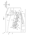
- FIG. 1 is a schematic view illustrating the configuration of the image forming apparatus 10 .
- Front, rear, right, left, up and down used in the following description correspond to directions of arrows in the drawings. These directions are determined for convenience of explanation, and the front-rear direction and the right-left direction of the apparatus are not limited to the directions of the arrows in the drawings.
- an encircled cross represents an arrow directed from the front side to the depth side of the paper of the drawing
- an encircled dot represents an arrow directed from the depth side to the front side of the paper of the drawing.
- the image forming apparatus 10 includes an image forming apparatus body 60 that accommodates constituent components.
- a storage section 12 that stores recording media P such as paper
- an image forming section 14 that forms images on the recording media P
- a transport section 16 that transports the recording media P from the storage section 12 to the image forming section 14 .
- an output section 18 into which the recording media P are output after the images are formed thereon by the image forming section 14 .
- the image forming section 14 includes image forming units 22 Y, 22 M, 22 C, and 22 K (hereinafter referred to as image forming units 22 Y to 22 K), serving as an example of an image forming body, which form toner images of yellow (Y), magenta (M), cyan (C), and black (K) colors, respectively, and an intermediate transfer belt 24 (transfer body) on which the toner images formed by the image forming units 22 Y to 22 K are to be transferred.
- image Y to 22 K serving as an example of an image forming body, which form toner images of yellow (Y), magenta (M), cyan (C), and black (K) colors, respectively, and an intermediate transfer belt 24 (transfer body) on which the toner images formed by the image forming units 22 Y to 22 K are to be transferred.
- the image forming section 14 further includes first transfer rollers 26 that transfer the toner images formed by the image forming units 22 Y to 22 K onto the intermediate transfer belt 24 , and a second transfer roller 28 that transfers the toner images, which are transferred on the intermediate transfer belt 24 by the first transfer rollers 26 , from the intermediate transfer belt 24 onto a recording medium P at a transfer position T.
- the intermediate transfer belt 24 has an annular shape, and is disposed on an upper side of the image forming units 22 Y to 22 K.
- winding rollers 42 , 43 , 44 , and 45 on which the intermediate transfer belt 24 is wound are provided on an inner peripheral side of the intermediate transfer belt 24 .
- the winding roller 42 serves as an opposed roller provided opposed to the second transfer roller 28 .
- the winding roller 43 serves as a driving roller.
- the winding roller 44 serves as a tension roller that applies tension to the intermediate transfer belt 24 .
- the intermediate transfer belt 24 When the winding roller 43 rotates, the intermediate transfer belt 24 circularly moves (rotates) in one direction (for example, a counterclockwise direction in FIG. 1 ) while being in contact with photoconductors 32 .
- the intermediate transfer belt 24 forms a part of a transfer unit 70 (to be described later).
- the transport section 16 includes a feed out roller 46 that feeds out a recording medium P stored in the storage section 12 , a transport path 48 through which the recording medium P fed out by the feed out roller 46 is transported, and transport rollers 50 that transport the recording medium P fed by the feed out roller 46 to the transfer position T.
- a fixing device 40 is provided to fix toner images transferred on the recording medium P by the second transfer roller 28 onto the recording medium P.
- output rollers 52 are provided to output the recording medium P into the output section 18 after the toner images are fixed on the recording medium P.
- the image forming units 22 Y to 22 K are provided in the image forming apparatus body 60 to be drawn out frontward from the image forming apparatus body 60 .
- the image forming units 22 Y to 22 K include their respective photoconductors 32 that rotate in one direction (for example, a clockwise direction in FIG. 1 ).
- both ends of a rotation shaft 33 of each photoconductor 32 are rotatably supported by bearing portions 32 A and 32 B, and the photoconductor 32 is rotated by driving force transmitted via a gear 35 . Since the image forming units 22 Y to 22 K are similarly configurated, the reference numerals of the components of the image forming units 22 M, 22 C, and 22 K are omitted in FIG. 1 .
- a charging roller 23 serves as a charging device that charges the photoconductor 32 .
- the exposure device 36 forms an electrostatic latent image on the photoconductor 32 by exposing the photoconductor 32 charged by the charging roller 23 .
- the developing device 38 forms a toner image by developing the electrostatic latent image formed on the photoconductor 32 by the exposure device 36 .
- Each of the image forming units 22 Y to 22 K includes a housing 29 having a front plate 29 A (see FIG. 2 ) and a rear plate 29 B (see FIG. 3 ).
- An upper part of the housing 29 is open, and a part of the outer periphery of the photoconductor 32 and a part of the outer periphery of the bearing portion 32 A are exposed upward, as illustrated in FIG. 2 .
- the bearing portion 32 A protrudes frontward from the front plate 29 A.
- the front plate 29 A is provided with an abutting member 100 (to be described later). Further, as illustrated in FIG. 3 , the bearing portion 32 B protrudes rearward from the rear plate 29 B.
- the image forming units 22 Y to 22 K to be drawn out from the image forming apparatus body 60 should each include at least the photoconductor 32 .
- the transfer unit 70 is provided in the image forming apparatus body 60 to be drawn out frontward from the image forming apparatus body 60 , similarly to the image forming units 22 Y to 22 K.
- the transfer unit 70 includes the intermediate transfer belt 24 serving as an example of a supported body, and a support body 71 that supports the intermediate transfer belt 24 .
- the support body 71 includes a front plate 72 serving as an example of a support portion, a rear plate 74 , and the above-described winding rollers 42 , 43 , 44 , and 45 .
- the front plate 72 is formed by a frame (plate) disposed on the front side (front side in the drawing direction) of the intermediate transfer belt 24 .
- the rear plate 74 is formed by a frame (plate) disposed on the rear side (depth side in the drawing direction) of the intermediate transfer belt 24 .
- the front plate 72 and the rear plate 74 support the intermediate transfer belt 24 by rotatably supporting both axial ends of each of the winding rollers 42 , 43 , 44 , and 45 on which the intermediate transfer belt 24 is wound.
- a handle 76 is provided as a grip portion to be gripped when drawing out the transfer unit 70 frontward from the image forming apparatus body 60 .
- the support body 71 is drawn out frontward from the image forming apparatus body 60 together with the intermediate transfer belt 24 while supporting the intermediate transfer belt 24 .
- FIG. 5 is a perspective view illustrating the specific structure of the image forming apparatus body 60 .
- the image forming apparatus body 60 includes a frame 61 and a housing 59 (exterior cover, see FIG. 1 ).
- the frame 61 includes a support column 62 , a front frame 64 (front wall), a rear frame 66 (rear wall), a right frame 68 (right side wall), a left frame 69 (left side wall), and a connecting frame 67 (connecting wall).
- the support column 62 forms a left front part of the image forming apparatus body 60 .
- a left end portion of the front frame 64 is fixed to the support column 62 .
- the left frame 69 connects an upper part of the left end portion of the front frame 64 to an upper part of a left end portion of the rear frame 66 .
- the right frame 68 connects a lower part of a right end portion of the front frame 64 and a lower part of a right end portion of the rear frame 66 .
- the front frame 64 has an opening 64 A from which the image forming units 22 Y to 22 K and the transfer unit 70 are to be drawn out frontward from a housed position (position illustrated in FIG. 6 ). To a lower edge of the opening 64 A, a front end portion of the connecting frame 67 is fixed. A rear end portion of the connecting frame 67 is fixed to the rear frame 66 . Thus, the connecting frame 67 connects the front frame 64 and the rear frame 66 .
- the connecting frame 67 is provided with guide members 67 A (guides) that guide the image forming units 22 Y to 22 K in a loading and unloading direction (drawing direction and inserting direction).
- the guide members 67 A extend on the connecting frame 67 in the front-rear direction.
- an unillustrated guide member is provided between the front frame 64 and the rear frame 66 to guide the transfer unit 70 in the loading and unloading direction.
- the unillustrated guide member and the guide members 67 A allow the image forming units 22 Y to 22 K and the transfer unit 70 to move in the front-rear direction between the housed position (position illustrated in FIG. 6 ) where the units are housed (loaded) in the image forming apparatus body 60 and a withdrawn position where the units are drawn out frontward from the housed position.
- FIG. 6 only the image forming unit 22 Y, of the image forming units 22 Y to 22 K, is illustrated.
- the intermediate transfer belt 24 and the rear plate 74 are located between the front frame 64 and the rear frame 66 .
- the intermediate transfer belt 24 is located in front of the front frame 64 .
- the photoconductors 32 are located between the front frame 64 and the rear frame 66 .
- the photoconductors 32 are located in front of the front frame 64 .
- the image forming units 22 Y to 22 K and the transfer unit 70 can be drawn out frontward together from the housed position to the withdrawn position.
- the image forming units 22 Y to 22 K and the transfer unit 70 may be drawn out independently.
- the intermediate transfer belt 24 is retreated from the photoconductors 32 , and abutting members 100 (to be described later) are removed from the front plate 72 of the transfer unit 70 .
- the transfer unit 70 and the image forming units 22 Y to 22 K are loaded and unloaded in the same direction.
- the image forming units 22 Y to 22 K can be inserted and drawn out in the loading and unloading direction of the transfer unit 70 .
- the transfer unit 70 and the image forming units 22 Y to 22 K can be exchanged after being drawn out from the image forming apparatus body 60 and removed from the image forming apparatus body 60 .
- the transfer unit 70 and the image forming units 22 Y to 22 K may be configurated so that they are drawn out from the image forming apparatus body 60 , but are not removed from the image forming apparatus body 60 .
- the image forming apparatus body 60 further includes an exterior cover (not illustrated) in front of the front plate 72 of the transfer unit 70 at the housed position and the front plate 29 A of each of the image forming units 22 Y to 22 K at the housed position. Therefore, the transfer unit 70 and the image forming units 22 Y to 22 K are drawn out after the exterior cover is opened.
- the rear frame 66 is provided with positioning members 90 and 91 that position the rear end portion of the transfer unit 70 .
- the positioning members 90 and 91 respectively have insertion holes 92 and 93 in which bearing portions (not illustrated) of the winding rollers 42 and 43 of the transfer unit 70 in a state housed in the image forming apparatus body 60 are to be inserted.
- bearing portions are inserted in the insertion holes 92 and 93 , the rear end portion of the transfer unit 70 is positioned relative to the rear frame 66 in the up-down direction and the right-left direction.
- contact portions are provided to be in contact with an upper edge 63 and a side edge 65 of the opening 64 A of the front frame 64 .
- the contact portions are in contact with the upper edge 63 and the side edge 65 of the opening 64 A, so that the front end portion of the transfer unit 70 is positioned relative to the front frame 64 in the up-down direction and the right-left direction.
- the rear surface of the front plate 72 is in contact with the front surface of the front frame 64 , so that the transfer unit 70 is positioned relative to the front frame 64 in the front-rear direction.
- the transfer unit 70 is positioned relative to the image forming apparatus body 60 (frame 61 ) serving as a positioning reference.
- the structure for positioning the transfer unit 70 relative to the image forming apparatus body 60 is not limited to the above-described structure.
- the rear frame 66 is provided with positioning members 80 that position the rear end portions of the image forming units 22 Y to 22 K.
- the positioning members 80 have their respective insertion holes 82 .
- bearing portions 32 B serving as an example of a projection, which are provided in the rear end portions (depth side end portions in the drawing direction) of the image forming units 22 Y to 22 K in the housed state are inserted rearward (in a direction opposite from the drawing direction).
- a C-shaped (arc-shaped) pressing member 84 is provided below each insertion hole 82 to press the corresponding bearing portion 32 B in the insertion hole 82 toward an upper edge of the insertion hole 82 .
- the pressing member 84 is movable up and down within a range such that the insertion hole 82 maintains a space where the bearing portion 32 B can be inserted, and is biased upward by a compression spring 86 .
- the bearing portion 32 B pushes down the pressing member 84 via a tapered portion 84 A and is inserted in the insertion hole 82 .
- the bearing portion 32 B inserted in the insertion hole 82 is pressed upward by the pressing member 84 , and the rear end portion of the corresponding one of the image forming units 22 Y to 22 K is positioned relative to the rear frame 66 in the up-down direction and the right-left direction serving as intersecting directions intersecting the drawing direction.
- each of the positioning grooves 78 includes inclined portions 78 B and 78 C and a top portion 78 A.
- the inclined portions 78 B and 78 C and the top portion 78 A are each formed by a flat face.
- the inclined portions 78 B and 78 C are inclined so as to gradually approach each other as they extend toward the upper side (toward the top portion 78 A).
- each of the image forming units 22 Y to 22 K is provided with an abutting member 100 that contacts the bearing portion 32 A with the corresponding positioning groove 78 by a force for pulling the front end portion of each of the image forming units 22 Y to 22 K toward the front plate 72 .
- the abutting member 100 includes a body 102 supported by the corresponding image forming unit 22 Y, 22 M, 22 C, or 22 K to be rotatable on a turn shaft 101 (see FIG. 10 ) extending in a direction of arrow A, a hook 104 provided on a side of the body 102 opposite from the turn shaft 101 , and tension springs 106 that pull the body 102 toward the hook 104 .
- a distal end portion 104 A of the hook 104 is caught in a catching hole 108 of the front plate 72 in the transfer unit 70 , and the corresponding image forming unit 22 Y, 22 M, 22 C, or 22 K is thereby pulled toward the transfer unit 70 .
- the bearing portion 32 A provided as an example of a projection in the front end portion (front-side end portion in the drawing direction) of the image forming unit 22 Y, 22 M, 22 C, or 22 K abuts on the corresponding positioning groove 78 in the upward direction intersecting the drawing direction. As illustrated in FIG.
- the bearing portion 32 A is circular or substantially circular when viewed from the front side (front side in the drawing direction), and abuts at two points on the inclined portions 78 B and 78 C of the positioning groove 78 .
- the bearing portion 32 A is kept abutting on the inclined portions 78 B and 78 C of the positioning groove 78 .
- the front end portion of the image forming unit 22 Y, 22 M, 22 C, or 22 K is positioned relative to the transfer unit 70 in the up-down direction and the right-left direction serving as the intersecting directions intersecting the drawing direction. That is, the front end portion of the image forming unit 22 Y, 22 M, 22 C, or 22 K is positioned relative to the transfer unit 70 that is positioned relative to the image forming apparatus body 60 .
- the image forming unit 22 Y, 22 M, 22 C, or 22 K is positioned relative to the image forming apparatus body 60 via the transfer unit 70 in the front-rear direction.
- the image forming units 22 Y to 22 K are positioned relative to the image forming apparatus body 60 (frame 61 ) serving as the positioning reference.
- the abutting member 100 is removed from the transfer unit 70 by being turned on the turn shaft 101 (see FIG. 10 ) in a direction of arrow B, as shown by a two-dot chain line in FIG. 9 .
- the abutting member 100 may be turnably provided in the transfer unit 70 , and the hook 104 may be caught in the corresponding image forming unit 22 Y, 22 M, 22 C, or 22 K. That is, it is only necessary that the abutting member 100 should be disposed to extend from the image forming unit 22 Y, 22 M, 22 C, or 22 K to the transfer unit 70 .
- the transfer unit 70 and the image forming units 22 Y to 22 K are loaded and unloaded in the same direction, and the image forming units 22 Y to 22 K can be inserted and withdrawn in the loading and unloading direction of the transfer unit 70 .
- the rear end portions of the image forming units 22 Y to 22 K are positioned relative to the rear frame 66 of the image forming apparatus body 60
- the front end portions of the image forming units 22 Y to 22 K are positioned relative to the front plate 72 of the transfer unit 70 that is positioned relative to the image forming apparatus body 60 .
- the image forming units 22 Y to 22 K housed in the image forming apparatus body 60 are positioned relative to the image forming apparatus body 60 .
- the present invention is not limited to this structures.
- a structure illustrated in FIG. 11 may be adopted.
- a shaft portion 310 serving as an example of a projection is rotatably supported by the rear frame 66 .
- the shaft portion 310 is rotated by driving force input from its rear end.
- a front end of the shaft portion 310 has a tapered shape.
- a gear 312 is provided at a position in an axial intermediate portion of the shaft portion 310 and in front of the rear frame 66 .
- Each photoconductor 32 has an insertion hole 320 into which the shaft portion 310 is to be inserted.
- a gear 322 is provided to be engaged with the gear 312 in the front-rear direction.
- the shaft portion 310 is inserted in the insertion hole 320 of the photoconductor 32 in the drawing direction, and the gear 312 and the gear 322 engage with each other in the drawing direction.
- the rear end portion of each of the image forming units 22 Y to 22 K is positioned relative to the rear frame 66 in the up-down direction and the right-left direction.
- the image forming apparatus 200 includes image forming units 22 Y to 22 K and a transport belt 202 serving as an example of a supported body.
- the transport belt 202 transports a recording medium P in a direction of arrow H, and color toner images formed by the image forming units 22 Y to 22 K are transferred onto the recording medium P.
- the transport belt 202 is configurated as a transport unit having a front plate 72 and a rear plate 74 , similarly to the above-described transfer unit 70 .
- the image forming body is formed by the plural image forming units 22 Y to 22 K in the exemplary embodiment, it may be formed by a single image forming unit.
- each of the image forming units 22 Y to 22 K is pulled toward the front plate 72 by the abutting member 100 in the exemplary embodiment, the present invention is not limited thereto.
- the image forming units 22 Y to 22 K may be pressed against the front plate 72 of the transfer unit 70 by compression springs provided in a lower part of the front frame 64 (for example, a lower edge of the opening 64 A).
- each of the image forming units 22 Y to 22 K is positioned by using the bearing portions 32 A and 32 B of the photoconductor 32 in the exemplary embodiment, the present invention is not limited thereto.
- the image forming units 22 Y to 22 K may be positioned by using columnar or cylindrical projecting portions projecting from the front plate 29 A and the rear plate 29 B of the housing 29 of each of the image forming units 22 Y to 22 K.
Landscapes
- Physics & Mathematics (AREA)
- General Physics & Mathematics (AREA)
- Engineering & Computer Science (AREA)
- Computer Vision & Pattern Recognition (AREA)
- Electrophotography Configuration And Component (AREA)
Abstract
Description
Claims (4)
Applications Claiming Priority (2)
| Application Number | Priority Date | Filing Date | Title |
|---|---|---|---|
| JP2014152310A JP6413435B2 (en) | 2014-07-25 | 2014-07-25 | Image forming apparatus |
| JP2014-152310 | 2014-07-25 |
Publications (2)
| Publication Number | Publication Date |
|---|---|
| US20160026148A1 US20160026148A1 (en) | 2016-01-28 |
| US9535397B2 true US9535397B2 (en) | 2017-01-03 |
Family
ID=55166714
Family Applications (1)
| Application Number | Title | Priority Date | Filing Date |
|---|---|---|---|
| US14/692,148 Active US9535397B2 (en) | 2014-07-25 | 2015-04-21 | Image forming apparatus |
Country Status (2)
| Country | Link |
|---|---|
| US (1) | US9535397B2 (en) |
| JP (1) | JP6413435B2 (en) |
Families Citing this family (2)
| Publication number | Priority date | Publication date | Assignee | Title |
|---|---|---|---|---|
| JP6520116B2 (en) * | 2014-12-26 | 2019-05-29 | 株式会社リコー | Image forming device |
| JP6451436B2 (en) * | 2015-03-19 | 2019-01-16 | 富士ゼロックス株式会社 | Image forming apparatus |
Citations (17)
| Publication number | Priority date | Publication date | Assignee | Title |
|---|---|---|---|---|
| US20010009621A1 (en) * | 1998-05-07 | 2001-07-26 | Ricoh Company, Ltd. | Image forming apparatus for reducing banding caused by vibration of stacked image forming cartridges |
| US20030053819A1 (en) * | 2001-07-05 | 2003-03-20 | Seiko Epson Corporation | System for forming color images |
| US20050220481A1 (en) * | 2004-02-20 | 2005-10-06 | Canon Kabushiki Kaisha | Process cartridge and image forming apparatus |
| US7031638B2 (en) * | 2002-10-25 | 2006-04-18 | Matsushita Electric Industrial Co., Ltd. | Color image forming apparatus with a removable and inclined intermediate transfer body unit |
| US20080138105A1 (en) * | 2006-12-08 | 2008-06-12 | Canon Kabushiki Kaisha | Process cartridge and electrophotographic image forming apparatus |
| US20080138106A1 (en) * | 2006-12-08 | 2008-06-12 | Canon Kabushiki Kaisha | Process cartridge and electrophotographic image forming apparatus |
| US20090028601A1 (en) * | 2007-05-15 | 2009-01-29 | Canon Kabushiki Kaisha | Image forming apparatus |
| US20090290903A1 (en) * | 2008-05-23 | 2009-11-26 | Canon Kabushiki Kaisha | Process cartridge and electrophotographic image forming apparatus |
| US20090297216A1 (en) * | 2008-05-27 | 2009-12-03 | Canon Kabushiki Kaisha | Process cartridge and image forming apparatus |
| JP2011065030A (en) | 2009-09-18 | 2011-03-31 | Fuji Xerox Co Ltd | Image forming apparatus |
| US20110299885A1 (en) * | 2010-06-02 | 2011-12-08 | Canon Kabushiki Kaisha | Image forming apparatus |
| JP2012150522A (en) | 2012-05-16 | 2012-08-09 | Canon Inc | Process cartridge and electrophotographic image forming apparatus |
| US20120243902A1 (en) * | 2011-03-25 | 2012-09-27 | Fuji Xerox Co., Ltd. | Image forming apparatus |
| US8280279B2 (en) * | 2008-05-23 | 2012-10-02 | Canon Kabushiki Kaisha | Process cartridge with first, second, and third portions-to-be-positioned by corresponding portions of image forming apparatus |
| JP2013007948A (en) | 2011-06-27 | 2013-01-10 | Brother Ind Ltd | Image forming device |
| JP2013007947A (en) | 2011-06-27 | 2013-01-10 | Brother Ind Ltd | Image forming device |
| US20140072332A1 (en) * | 2012-09-13 | 2014-03-13 | Oki Data Corporation | Image forming apparatus |
Family Cites Families (6)
| Publication number | Priority date | Publication date | Assignee | Title |
|---|---|---|---|---|
| JPH0723356U (en) * | 1993-09-29 | 1995-04-25 | ミノルタ株式会社 | Image forming device |
| JP4373708B2 (en) * | 2003-05-20 | 2009-11-25 | 株式会社リコー | Image forming apparatus |
| JP4667180B2 (en) * | 2005-09-09 | 2011-04-06 | キヤノン株式会社 | Image forming apparatus |
| KR20120048327A (en) * | 2010-11-05 | 2012-05-15 | 삼성전자주식회사 | Image forming apparatus |
| JP5665490B2 (en) * | 2010-11-10 | 2015-02-04 | キヤノン株式会社 | Image forming apparatus |
| JP5659206B2 (en) * | 2012-09-28 | 2015-01-28 | 株式会社沖データ | Image forming apparatus |
-
2014
- 2014-07-25 JP JP2014152310A patent/JP6413435B2/en active Active
-
2015
- 2015-04-21 US US14/692,148 patent/US9535397B2/en active Active
Patent Citations (19)
| Publication number | Priority date | Publication date | Assignee | Title |
|---|---|---|---|---|
| US20010009621A1 (en) * | 1998-05-07 | 2001-07-26 | Ricoh Company, Ltd. | Image forming apparatus for reducing banding caused by vibration of stacked image forming cartridges |
| US20030053819A1 (en) * | 2001-07-05 | 2003-03-20 | Seiko Epson Corporation | System for forming color images |
| US7031638B2 (en) * | 2002-10-25 | 2006-04-18 | Matsushita Electric Industrial Co., Ltd. | Color image forming apparatus with a removable and inclined intermediate transfer body unit |
| US20050220481A1 (en) * | 2004-02-20 | 2005-10-06 | Canon Kabushiki Kaisha | Process cartridge and image forming apparatus |
| US20080138105A1 (en) * | 2006-12-08 | 2008-06-12 | Canon Kabushiki Kaisha | Process cartridge and electrophotographic image forming apparatus |
| US20080138106A1 (en) * | 2006-12-08 | 2008-06-12 | Canon Kabushiki Kaisha | Process cartridge and electrophotographic image forming apparatus |
| US20090028601A1 (en) * | 2007-05-15 | 2009-01-29 | Canon Kabushiki Kaisha | Image forming apparatus |
| US8280279B2 (en) * | 2008-05-23 | 2012-10-02 | Canon Kabushiki Kaisha | Process cartridge with first, second, and third portions-to-be-positioned by corresponding portions of image forming apparatus |
| US20090290903A1 (en) * | 2008-05-23 | 2009-11-26 | Canon Kabushiki Kaisha | Process cartridge and electrophotographic image forming apparatus |
| US20090297216A1 (en) * | 2008-05-27 | 2009-12-03 | Canon Kabushiki Kaisha | Process cartridge and image forming apparatus |
| JP2011065030A (en) | 2009-09-18 | 2011-03-31 | Fuji Xerox Co Ltd | Image forming apparatus |
| US20110299885A1 (en) * | 2010-06-02 | 2011-12-08 | Canon Kabushiki Kaisha | Image forming apparatus |
| US20120243902A1 (en) * | 2011-03-25 | 2012-09-27 | Fuji Xerox Co., Ltd. | Image forming apparatus |
| JP2013007948A (en) | 2011-06-27 | 2013-01-10 | Brother Ind Ltd | Image forming device |
| JP2013007947A (en) | 2011-06-27 | 2013-01-10 | Brother Ind Ltd | Image forming device |
| US8768206B2 (en) | 2011-06-27 | 2014-07-01 | Brother Kogyo Kabushiki Kaisha | Image forming apparatus having photosensitive drum moving mechanism |
| US8892002B2 (en) | 2011-06-27 | 2014-11-18 | Brother Kogyo Kabushiki Kaisha | Image forming apparatus having photosensitive drum moving mechanism |
| JP2012150522A (en) | 2012-05-16 | 2012-08-09 | Canon Inc | Process cartridge and electrophotographic image forming apparatus |
| US20140072332A1 (en) * | 2012-09-13 | 2014-03-13 | Oki Data Corporation | Image forming apparatus |
Also Published As
| Publication number | Publication date |
|---|---|
| JP6413435B2 (en) | 2018-10-31 |
| US20160026148A1 (en) | 2016-01-28 |
| JP2016031385A (en) | 2016-03-07 |
Similar Documents
| Publication | Publication Date | Title |
|---|---|---|
| JP5517989B2 (en) | Process cartridge and image forming apparatus | |
| US9684279B2 (en) | Image forming apparatus with an insertion port configured for a process cartridge, usable with the image forming apparatus | |
| US8886091B2 (en) | Detachable unit and image forming apparatus | |
| US10322893B2 (en) | Image forming apparatus | |
| JP2009069701A (en) | Fixing apparatus and image forming apparatus | |
| JP5724358B2 (en) | Conveying apparatus and image forming apparatus | |
| US9829823B2 (en) | Charging device having movable charging member and movable cleaning member and image forming apparatus including the charging device | |
| CN103576515A (en) | Fixing device and image forming apparatus | |
| US9535397B2 (en) | Image forming apparatus | |
| US9977375B2 (en) | Image forming device | |
| JP2016098055A (en) | Print medium supply apparatus and image forming apparatus | |
| US10036995B2 (en) | Detachable device for image forming apparatus and image forming apparatus | |
| US9405209B2 (en) | Image forming unit and image forming apparatus provided with same | |
| JP5169520B2 (en) | Image forming apparatus | |
| JP2015034905A (en) | Image forming unit and image forming apparatus having the same | |
| US20140064802A1 (en) | Rotating body support device and fixing device having rotating body support device, and image forming apparatus | |
| JP2016114649A (en) | Interval adjustment mechanism and image formation device | |
| JP5326427B2 (en) | Image forming apparatus | |
| US9465327B1 (en) | Transfer mechanism and image forming apparatus | |
| JP6358218B2 (en) | Image forming apparatus | |
| CN111596535A (en) | Program cartridge and image forming apparatus | |
| US9581957B2 (en) | Image forming apparatus and detachable component | |
| US11550241B1 (en) | Image forming apparatus | |
| JP6357885B2 (en) | Image forming apparatus | |
| JP5593898B2 (en) | Image forming apparatus |
Legal Events
| Date | Code | Title | Description |
|---|---|---|---|
| AS | Assignment |
Owner name: FUJI XEROX CO., LTD., JAPAN Free format text: ASSIGNMENT OF ASSIGNORS INTEREST;ASSIGNOR:KONDO, TAKAYUKI;REEL/FRAME:035460/0850 Effective date: 20150305 |
|
| STCF | Information on status: patent grant |
Free format text: PATENTED CASE |
|
| MAFP | Maintenance fee payment |
Free format text: PAYMENT OF MAINTENANCE FEE, 4TH YEAR, LARGE ENTITY (ORIGINAL EVENT CODE: M1551); ENTITY STATUS OF PATENT OWNER: LARGE ENTITY Year of fee payment: 4 |
|
| AS | Assignment |
Owner name: FUJIFILM BUSINESS INNOVATION CORP., JAPAN Free format text: CHANGE OF NAME;ASSIGNOR:FUJI XEROX CO., LTD.;REEL/FRAME:058287/0056 Effective date: 20210401 |
|
| MAFP | Maintenance fee payment |
Free format text: PAYMENT OF MAINTENANCE FEE, 8TH YEAR, LARGE ENTITY (ORIGINAL EVENT CODE: M1552); ENTITY STATUS OF PATENT OWNER: LARGE ENTITY Year of fee payment: 8 |