US9534723B2 - Method of brazing, in particular induction brazing, and assembly - Google Patents
Method of brazing, in particular induction brazing, and assembly Download PDFInfo
- Publication number
- US9534723B2 US9534723B2 US13/894,472 US201313894472A US9534723B2 US 9534723 B2 US9534723 B2 US 9534723B2 US 201313894472 A US201313894472 A US 201313894472A US 9534723 B2 US9534723 B2 US 9534723B2
- Authority
- US
- United States
- Prior art keywords
- compensation element
- component
- pipe
- opening
- support section
- Prior art date
- Legal status (The legal status is an assumption and is not a legal conclusion. Google has not performed a legal analysis and makes no representation as to the accuracy of the status listed.)
- Expired - Fee Related, expires
Links
Images


Classifications
-
- F—MECHANICAL ENGINEERING; LIGHTING; HEATING; WEAPONS; BLASTING
- F16—ENGINEERING ELEMENTS AND UNITS; GENERAL MEASURES FOR PRODUCING AND MAINTAINING EFFECTIVE FUNCTIONING OF MACHINES OR INSTALLATIONS; THERMAL INSULATION IN GENERAL
- F16L—PIPES; JOINTS OR FITTINGS FOR PIPES; SUPPORTS FOR PIPES, CABLES OR PROTECTIVE TUBING; MEANS FOR THERMAL INSULATION IN GENERAL
- F16L41/00—Branching pipes; Joining pipes to walls
- F16L41/02—Branch units, e.g. made in one piece, welded, riveted
- F16L41/021—T- or cross-pieces
-
- B—PERFORMING OPERATIONS; TRANSPORTING
- B23—MACHINE TOOLS; METAL-WORKING NOT OTHERWISE PROVIDED FOR
- B23K—SOLDERING OR UNSOLDERING; WELDING; CLADDING OR PLATING BY SOLDERING OR WELDING; CUTTING BY APPLYING HEAT LOCALLY, e.g. FLAME CUTTING; WORKING BY LASER BEAM
- B23K1/00—Soldering, e.g. brazing, or unsoldering
- B23K1/002—Soldering by means of induction heating
-
- B—PERFORMING OPERATIONS; TRANSPORTING
- B23—MACHINE TOOLS; METAL-WORKING NOT OTHERWISE PROVIDED FOR
- B23K—SOLDERING OR UNSOLDERING; WELDING; CLADDING OR PLATING BY SOLDERING OR WELDING; CUTTING BY APPLYING HEAT LOCALLY, e.g. FLAME CUTTING; WORKING BY LASER BEAM
- B23K1/00—Soldering, e.g. brazing, or unsoldering
- B23K1/14—Soldering, e.g. brazing, or unsoldering specially adapted for soldering seams
- B23K1/18—Soldering, e.g. brazing, or unsoldering specially adapted for soldering seams circumferential seams, e.g. of shells
-
- B—PERFORMING OPERATIONS; TRANSPORTING
- B23—MACHINE TOOLS; METAL-WORKING NOT OTHERWISE PROVIDED FOR
- B23K—SOLDERING OR UNSOLDERING; WELDING; CLADDING OR PLATING BY SOLDERING OR WELDING; CUTTING BY APPLYING HEAT LOCALLY, e.g. FLAME CUTTING; WORKING BY LASER BEAM
- B23K3/00—Tools, devices or special appurtenances for soldering, e.g. brazing, or unsoldering, not specially adapted for particular methods
- B23K3/04—Heating appliances
- B23K3/047—Heating appliances electric
- B23K3/0475—Heating appliances electric using induction effects, e.g. Kelvin or skin effects
-
- F—MECHANICAL ENGINEERING; LIGHTING; HEATING; WEAPONS; BLASTING
- F16—ENGINEERING ELEMENTS AND UNITS; GENERAL MEASURES FOR PRODUCING AND MAINTAINING EFFECTIVE FUNCTIONING OF MACHINES OR INSTALLATIONS; THERMAL INSULATION IN GENERAL
- F16L—PIPES; JOINTS OR FITTINGS FOR PIPES; SUPPORTS FOR PIPES, CABLES OR PROTECTIVE TUBING; MEANS FOR THERMAL INSULATION IN GENERAL
- F16L41/00—Branching pipes; Joining pipes to walls
- F16L41/08—Joining pipes to walls or pipes, the joined pipe axis being perpendicular to the plane of a wall or to the axis of another pipe
- F16L41/082—Non-disconnectable joints, e.g. soldered, adhesive or caulked joints
- F16L41/084—Soldered joints
Definitions
- the present invention relates to a method of brazing and in particular of induction brazing, and to an assembly produced via a brazing method.
- brazing and soldering processes are well suited to connect two metallic components with each other.
- brazing and soldering will be collectively referred to as brazing, but it should be understood that the present invention is intended to include both brazing and soldering processes.
- heat is supplied not to a closely limited surface area but, rather, either to the entire component when a furnace brazing method is made use of, or in the region of the brazing point when an induction brazing method is made use of.
- the induction of an electric current in the components to be connected generates heat in the component itself, which heats the component such that the brazing material arranged there will fuse.
- a brazing method for connecting a pipe with a component provided with an opening utilizes a compensation element that is arranged between an end of the pipe and the opening of the component.
- the compensation element includes a support section and an insertion section, and an inside diameter of the compensation element is smaller than a diameter of the opening in the component.
- the insertion section is inserted into the end of the pipe, and the support section is located between the pipe and the component and rests on the component at the edge of the opening.
- the compensation element and the pipe and also the component, in the region of the compensation element are heated to a temperature above the melting temperature of brazing material that is present in the region of the brazing points.
- the compensation element allows, in a simple and cost-effective manner, a compensation of tolerances between the end of the pipe and the opening in the component.
- Use of the compensation element allows tolerances in the radial direction between the inside diameter of the pipe and the diameter of the opening to be compensated.
- a suitable brazing method is, more particularly, an induction brazing method.
- a furnace brazing method may also be used.
- the inside diameter of the compensation element more particularly the inside diameter of the insertion section, is smaller than the diameter of the opening in the component, any deviations in the diameter of the pipe have no effect on the effective flow cross-section because the latter is always defined by the compensation element.
- the compensation element may be made use of for compensating both an oblique pipe position and an excessively large distance between the pipe end and the component, and also a lateral offset between the opening in the component and the pipe.
- the insertion section of the compensation element is preferably designed to be cylindrical, whereas the support section preferably has the shape of a flat ring.
- the component may, for example, be a pipe which has a considerably larger diameter than the pipe to be connected with the component.
- the brazing material may be simply preplaced in the form of filler wire rings prior to heating at the brazing points to be formed.
- Brazing points may be provided, for example, at the pipe end between the inside of the pipe and the outside of the insertion section of the compensation element and/or between a portion on the edge of the opening of the component and a lower side of the support section of the compensation element.
- the insertion section Prior to the brazing, the insertion section preferably has a radial clearance in relation to the inside of the pipe. This clearance allows the pipe and the compensation element to be arranged such that the pipe can be oriented exactly in the desired position in relation to the component and any deviations in length, diameter, or inclination can be compensated.
- the gap between the outside of the insertion section and the inside of the pipe is so small that the liquid filler material is pulled into the gap by capillary forces and can in this way be evenly distributed over the entire brazing point.
- the brazed joint between the pipe and the insertion section of the compensation element and the brazed joint between the component and the support section of the compensation element may be produced in one processing step, which saves process time.
- An assembly according to the invention includes a pipe, a component having an opening, and a compensation element, as may be used, for example, for producing a brazed joint as described above.
- the inside diameter of the compensation element is smaller than the diameter of the opening in the component, which results in the advantages described.
- the outside diameter of the insertion section of the compensation element is preferably only slightly smaller than the inside diameter of the end of the pipe, in order to ensure a good connection by induction brazing between these two components.
- the support section of the compensation element may form a flat ring, the outside diameter of the ring being larger than the diameter of the opening, and the inside diameter of the ring (which advantageously corresponds to the inside diameter of the insertion section) being smaller than the diameter of the opening.
- outside diameter of the insertion section is smaller than the inside diameter of the end of the pipe, and the outside diameter of the ring is larger than the outside diameter of the pipe, a face side of the pipe end will always meet the support section of the compensation element. In this way, it is possible, for example, to use the compensation element to compensate a deviation in length over part of the circumference or over the entire circumference of the pipe end.
- the compensation element is preferably designed such that the length of the insertion section is approximately as large as the width of the support section in the radial direction.
- the width of the support section may correspond to the width of the flat ring formed by the support section.
- FIG. 1 shows a schematic illustration of a pipe and a component having an opening, which are to be connected with each other via a brazing method
- FIG. 2 shows a schematic perspective illustration of the components illustrated in FIG. 1 ;
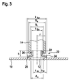
- FIG. 3 shows a schematic sectional view of an assembly according to the invention for carrying out a brazing method according to the invention.
- FIGS. 1 and 2 show a component 10 , in this case a large-diameter pipe (see FIG. 2 ) having an opening 12 .
- a pipe 14 having a markedly smaller diameter is to be connected with the component 10 by firmly connecting a face side 16 of the pipe end with a substantially flat portion 18 which circumferentially surrounds the opening 12 .
- an induction brazing method will be described below.
- a furnace brazing method may also be used. It is basically also possible to weld the two components to each other.
- the pipe 14 may, for example, be tilted by an angle ⁇ (shown exaggerated in FIG. 1 ).
- the longitudinal axis A R of the pipe 14 may also be offset by an amount x in relation to the surface normal A O of the opening 12 .
- There may also exist a deviation in the height along the longitudinal axis A R of the pipe 14 which leads to a gap s between the portion 18 on the edge of the opening 12 and the face side 16 of the pipe 14 . It is also possible for a plurality of the deviations described to occur at the same time.
- the compensation element 20 has an insertion section 22 which is in the form of a cylinder tube, and a support section 24 which directly adjoins the insertion section 22 at a right angle and which is shaped in the form of a flat ring.
- the insertion section 22 and the support section 24 are substantially perpendicular to each other.
- the inside diameter k Ai of the support section 24 which also corresponds to the inside diameter of the insertion section 22 , is smaller than the diameter d O of the opening 12 .
- the outside diameter k Aa of the support section 24 is larger than the diameter d O of the opening 12 .
- the width k R of the support section 24 in the radial direction r corresponds to half the difference between the outside diameter k Aa and the inside diameter k Ai .
- the width k R is approximately as large as a height h of the insertion section 22 of the compensation element 20 perpendicular to the support section 24 .
- the outside diameter k Ea of the insertion section 22 is slightly smaller than the inside diameter R i of the end of the pipe 14 .
- the outside diameter k Aa of the support section 24 is larger than the outside diameter R a of the end of the pipe 14 .
- the compensation element 20 is produced, for example, by reshaping from a suitable metal that is well suited to be inductively heated.
- the compensation element 20 is placed on the component 10 so that the edge of the opening 12 is fully covered by the support section 24 and the insertion section 22 is positioned fully over the opening 12 .
- the later flow cross-section is defined by the inside diameter k Ai of the compensation element 20 .
- the compensation element 20 may be placed flatly on the portion 18 at the edge of the opening 12 .
- a ring of a brazing material 26 is preplaced between the component 10 and the support section 24 .
- brazing paste may also be used. It is also possible to make use of punched rings of brazing foil.
- the end of the pipe 14 is fitted onto the insertion section 22 of the compensation element 20 and the pipe 14 is oriented in its desired position with respect to the component 10 .
- a ring of a brazing material 26 is preplaced between the pipe 14 and the insertion section 22 .
- An induction coil (not illustrated) is arranged around the assembly made up of the component 10 , the pipe 14 and the compensation element 20 , so that the current flow induced by the coil heats the end of the pipe 14 , the compensation element 20 , and the portion 18 at the edge of the opening 12 to above a temperature at which the entire amount of brazing material 26 placed at the brazing points will melt.
- the gap between the inner wall of the pipe 14 and the outer wall of the insertion section 22 and also the gap between the component 10 and the lower side of the support section 24 are so small that the brazing material 26 will evenly distribute by capillary effects in the gaps existing there, and a brazed joint is produced which is tight over the entire circumference.
Landscapes
- Engineering & Computer Science (AREA)
- Mechanical Engineering (AREA)
- General Engineering & Computer Science (AREA)
- Health & Medical Sciences (AREA)
- Dermatology (AREA)
- General Health & Medical Sciences (AREA)
- Non-Disconnectible Joints And Screw-Threaded Joints (AREA)
- General Induction Heating (AREA)
Abstract
Description
Claims (18)
Applications Claiming Priority (3)
| Application Number | Priority Date | Filing Date | Title |
|---|---|---|---|
| DE102012009615.1 | 2012-05-15 | ||
| DE102012009615 | 2012-05-15 | ||
| DE102012009615.1A DE102012009615B4 (en) | 2012-05-15 | 2012-05-15 | Method of soldering and assembly |
Publications (2)
| Publication Number | Publication Date |
|---|---|
| US20130307261A1 US20130307261A1 (en) | 2013-11-21 |
| US9534723B2 true US9534723B2 (en) | 2017-01-03 |
Family
ID=49510769
Family Applications (1)
| Application Number | Title | Priority Date | Filing Date |
|---|---|---|---|
| US13/894,472 Expired - Fee Related US9534723B2 (en) | 2012-05-15 | 2013-05-15 | Method of brazing, in particular induction brazing, and assembly |
Country Status (4)
| Country | Link |
|---|---|
| US (1) | US9534723B2 (en) |
| KR (1) | KR20130127947A (en) |
| CN (1) | CN103418871B (en) |
| DE (1) | DE102012009615B4 (en) |
Cited By (2)
| Publication number | Priority date | Publication date | Assignee | Title |
|---|---|---|---|---|
| US11208934B2 (en) | 2019-02-25 | 2021-12-28 | Cummins Emission Solutions Inc. | Systems and methods for mixing exhaust gas and reductant |
| US12109655B2 (en) * | 2022-10-17 | 2024-10-08 | Houser Products, Llc | Metal fabrication locator device and methods |
Families Citing this family (2)
| Publication number | Priority date | Publication date | Assignee | Title |
|---|---|---|---|---|
| CN105805467A (en) * | 2016-04-12 | 2016-07-27 | 镇江市神龙电器管件有限公司 | Hot-melt connection method of pipeline connecting piece |
| DE102019001246A1 (en) * | 2019-02-20 | 2020-08-20 | Eberspächer Exhaust Technology GmbH & Co. KG | Probe socket for an exhaust system |
Citations (43)
| Publication number | Priority date | Publication date | Assignee | Title |
|---|---|---|---|---|
| US1452238A (en) * | 1922-04-03 | 1923-04-17 | Finnigan John Joseph | Method of making flanged tank couplings |
| US1556596A (en) * | 1923-03-19 | 1925-10-13 | Augustine Davis Jr | Manhole or like structure |
| US1883439A (en) * | 1930-03-06 | 1932-10-18 | David G Adams | Sewer pipe tap |
| US1908821A (en) * | 1930-04-29 | 1933-05-16 | Chase Companies Inc | Branch-fitting for pipes |
| US1924121A (en) * | 1930-08-18 | 1933-08-29 | Smith Corp A O | Welded manway for pressure vessels |
| US1933772A (en) * | 1929-04-19 | 1933-11-07 | Smith Corp A O | Thick walled pressure vessel |
| US1933710A (en) * | 1931-02-12 | 1933-11-07 | Chase Companies Inc | Branch-fitting for water-tubes and method of making same |
| US1937606A (en) * | 1932-03-09 | 1933-12-05 | Taylor James Hall | Method of attaching nozzles to hollow bodies |
| US1977112A (en) * | 1934-10-16 | Branch fitting for tubes and the like | ||
| US2136474A (en) * | 1936-05-15 | 1938-11-15 | Smith Corp A O | Alloy lining for tubular parts |
| US2216033A (en) * | 1938-06-01 | 1940-09-24 | Kellogg M W Co | Method of forming lined connectors |
| US2496677A (en) * | 1947-04-19 | 1950-02-07 | American Car & Foundry Co | Tank car nozzle |
| US2528040A (en) * | 1944-10-28 | 1950-10-31 | Logan R Crouch | Method of brazing and welding |
| US2981556A (en) * | 1957-05-16 | 1961-04-25 | Bonney Forge & Tool Works | Welding stress-free outlet fitting |
| US3516692A (en) * | 1968-02-09 | 1970-06-23 | Allied Piping Products Co Of P | Branch pipe connection |
| US3567257A (en) * | 1968-10-11 | 1971-03-02 | Connecticut Research & Mfg Cor | Tapered pipe joint |
| US3594025A (en) * | 1968-11-12 | 1971-07-20 | Adolph A Wagner | Pipe railing fitting |
| US3649055A (en) * | 1970-06-29 | 1972-03-14 | Norman P Nilsen | Clamp fitting with seal for plastic pipe |
| US3787033A (en) * | 1972-08-14 | 1974-01-22 | Crane Veyor Corp | Joint for tubular structure |
| US3891249A (en) * | 1973-02-16 | 1975-06-24 | Charles H Moore | Double plate welded outlet fitting and method of obtaining the same |
| US3971500A (en) * | 1975-07-16 | 1976-07-27 | General Electric Company | Method of metallurgically joining tubing to a wall segment |
| US4015321A (en) * | 1974-12-23 | 1977-04-05 | Witter Melvin L | Welded pipe fitting and method of making same |
| US4103940A (en) * | 1976-12-30 | 1978-08-01 | Elkhart Products Corporation | Branch fitting for a pipe |
| US4179141A (en) * | 1978-05-04 | 1979-12-18 | Allied Piping Products Company, Inc. | Branch connection fitting |
| US4305429A (en) * | 1978-11-22 | 1981-12-15 | Framatome | Coupling for two conduits |
| US4351469A (en) * | 1978-08-31 | 1982-09-28 | Stretch Devices, Inc. | Method of making railing |
| US4438955A (en) * | 1982-01-21 | 1984-03-27 | Wfi International, Inc. | Acute angled vessel connector |
| US4556240A (en) * | 1981-07-29 | 1985-12-03 | Kawasaki Jukogyo Kabushiki Kaisha | Corrosion-resistant, double-wall pipe structures |
| US4613168A (en) * | 1982-03-04 | 1986-09-23 | Avon Industrial Polymers Limited | Method of making branches in hoses |
| US4645242A (en) * | 1985-08-26 | 1987-02-24 | Dieterich Standard Corp. | High pressure mounting with positive lock |
| US5056704A (en) * | 1988-02-22 | 1991-10-15 | Tube Forming, Inc. | Tube fitting having a saddle bead with conforming pilot |
| US5228727A (en) * | 1989-12-28 | 1993-07-20 | Showa Aluminum Corporation | Tubular body having pipe joint member attached thereto and method of producing same |
| CN2163289Y (en) | 1993-07-02 | 1994-04-27 | 张卓然 | Split saddle reinforced board |
| US5951062A (en) * | 1997-05-28 | 1999-09-14 | Miller; Daniel A. | Saddle-less fitting |
| US6126208A (en) * | 1997-03-03 | 2000-10-03 | Usui Kokusai Sangyo Kaisha Limited | Common rail and method of manufacturing the same |
| US6552294B1 (en) * | 2001-10-02 | 2003-04-22 | Delphi Technologies, Inc. | Method for metallurgically attaching together two members |
| US6698801B1 (en) * | 1998-07-15 | 2004-03-02 | Robert Bosch Gmbh | Prestressed welded connection stub for a fuel injection system for internal combustion engines |
| US7082960B2 (en) * | 2004-08-03 | 2006-08-01 | Young Sik Kim | Pipe tapping apparatus |
| US7237807B2 (en) * | 2003-05-21 | 2007-07-03 | Calsonic Kansei Corporation | Pipe connecting structure for a heat exchanger |
| US7966857B1 (en) * | 2007-01-04 | 2011-06-28 | Sheet Metal Connectors, Inc. | Method of making an HVAC high efficiency takeoff connector |
| CN102161152A (en) | 2011-01-27 | 2011-08-24 | 高密市中亚暖通设备有限公司 | Processing method of heating radiator |
| CN102225483A (en) | 2011-06-08 | 2011-10-26 | 沈阳飞机工业(集团)有限公司 | Welding method of vertically brazed joint of stainless steel conduit |
| US20120175872A1 (en) * | 2009-09-30 | 2012-07-12 | Kevin Albert Lindsey | Pipe joining device |
Family Cites Families (3)
| Publication number | Priority date | Publication date | Assignee | Title |
|---|---|---|---|---|
| JP4707462B2 (en) | 2005-05-31 | 2011-06-22 | カルソニックカンセイ株式会社 | Piping connection structure of heat exchanger |
| SE0802203L (en) | 2008-10-16 | 2010-03-02 | Alfa Laval Corp Ab | Hard brazed heat exchanger and method of manufacturing brazed heat exchanger |
| WO2010104802A2 (en) | 2009-03-08 | 2010-09-16 | Radyne Corporation | Braze joining of workpieces |
-
2012
- 2012-05-15 DE DE102012009615.1A patent/DE102012009615B4/en active Active
-
2013
- 2013-05-15 KR KR1020130054715A patent/KR20130127947A/en not_active Ceased
- 2013-05-15 CN CN201310179884.7A patent/CN103418871B/en not_active Expired - Fee Related
- 2013-05-15 US US13/894,472 patent/US9534723B2/en not_active Expired - Fee Related
Patent Citations (44)
| Publication number | Priority date | Publication date | Assignee | Title |
|---|---|---|---|---|
| US1977112A (en) * | 1934-10-16 | Branch fitting for tubes and the like | ||
| US1452238A (en) * | 1922-04-03 | 1923-04-17 | Finnigan John Joseph | Method of making flanged tank couplings |
| US1556596A (en) * | 1923-03-19 | 1925-10-13 | Augustine Davis Jr | Manhole or like structure |
| US1933772A (en) * | 1929-04-19 | 1933-11-07 | Smith Corp A O | Thick walled pressure vessel |
| US1883439A (en) * | 1930-03-06 | 1932-10-18 | David G Adams | Sewer pipe tap |
| US1908821A (en) * | 1930-04-29 | 1933-05-16 | Chase Companies Inc | Branch-fitting for pipes |
| US1924121A (en) * | 1930-08-18 | 1933-08-29 | Smith Corp A O | Welded manway for pressure vessels |
| US1933710A (en) * | 1931-02-12 | 1933-11-07 | Chase Companies Inc | Branch-fitting for water-tubes and method of making same |
| US1937606A (en) * | 1932-03-09 | 1933-12-05 | Taylor James Hall | Method of attaching nozzles to hollow bodies |
| US2136474A (en) * | 1936-05-15 | 1938-11-15 | Smith Corp A O | Alloy lining for tubular parts |
| US2216033A (en) * | 1938-06-01 | 1940-09-24 | Kellogg M W Co | Method of forming lined connectors |
| US2528040A (en) * | 1944-10-28 | 1950-10-31 | Logan R Crouch | Method of brazing and welding |
| US2496677A (en) * | 1947-04-19 | 1950-02-07 | American Car & Foundry Co | Tank car nozzle |
| US2981556A (en) * | 1957-05-16 | 1961-04-25 | Bonney Forge & Tool Works | Welding stress-free outlet fitting |
| US3516692A (en) * | 1968-02-09 | 1970-06-23 | Allied Piping Products Co Of P | Branch pipe connection |
| US3567257A (en) * | 1968-10-11 | 1971-03-02 | Connecticut Research & Mfg Cor | Tapered pipe joint |
| US3594025A (en) * | 1968-11-12 | 1971-07-20 | Adolph A Wagner | Pipe railing fitting |
| US3649055A (en) * | 1970-06-29 | 1972-03-14 | Norman P Nilsen | Clamp fitting with seal for plastic pipe |
| US3787033A (en) * | 1972-08-14 | 1974-01-22 | Crane Veyor Corp | Joint for tubular structure |
| US3891249A (en) * | 1973-02-16 | 1975-06-24 | Charles H Moore | Double plate welded outlet fitting and method of obtaining the same |
| US4015321A (en) * | 1974-12-23 | 1977-04-05 | Witter Melvin L | Welded pipe fitting and method of making same |
| US3971500A (en) * | 1975-07-16 | 1976-07-27 | General Electric Company | Method of metallurgically joining tubing to a wall segment |
| US4103940A (en) * | 1976-12-30 | 1978-08-01 | Elkhart Products Corporation | Branch fitting for a pipe |
| US4179141A (en) * | 1978-05-04 | 1979-12-18 | Allied Piping Products Company, Inc. | Branch connection fitting |
| US4351469A (en) * | 1978-08-31 | 1982-09-28 | Stretch Devices, Inc. | Method of making railing |
| US4305429A (en) * | 1978-11-22 | 1981-12-15 | Framatome | Coupling for two conduits |
| US4556240A (en) * | 1981-07-29 | 1985-12-03 | Kawasaki Jukogyo Kabushiki Kaisha | Corrosion-resistant, double-wall pipe structures |
| US4438955A (en) * | 1982-01-21 | 1984-03-27 | Wfi International, Inc. | Acute angled vessel connector |
| US4613168A (en) * | 1982-03-04 | 1986-09-23 | Avon Industrial Polymers Limited | Method of making branches in hoses |
| US4645242A (en) * | 1985-08-26 | 1987-02-24 | Dieterich Standard Corp. | High pressure mounting with positive lock |
| US5056704A (en) * | 1988-02-22 | 1991-10-15 | Tube Forming, Inc. | Tube fitting having a saddle bead with conforming pilot |
| US5228727A (en) * | 1989-12-28 | 1993-07-20 | Showa Aluminum Corporation | Tubular body having pipe joint member attached thereto and method of producing same |
| US5280971A (en) * | 1989-12-28 | 1994-01-25 | Showa Aluminum Corporation | Tubular body having pipe joint member attached thereto with brazing ring |
| CN2163289Y (en) | 1993-07-02 | 1994-04-27 | 张卓然 | Split saddle reinforced board |
| US6126208A (en) * | 1997-03-03 | 2000-10-03 | Usui Kokusai Sangyo Kaisha Limited | Common rail and method of manufacturing the same |
| US5951062A (en) * | 1997-05-28 | 1999-09-14 | Miller; Daniel A. | Saddle-less fitting |
| US6698801B1 (en) * | 1998-07-15 | 2004-03-02 | Robert Bosch Gmbh | Prestressed welded connection stub for a fuel injection system for internal combustion engines |
| US6552294B1 (en) * | 2001-10-02 | 2003-04-22 | Delphi Technologies, Inc. | Method for metallurgically attaching together two members |
| US7237807B2 (en) * | 2003-05-21 | 2007-07-03 | Calsonic Kansei Corporation | Pipe connecting structure for a heat exchanger |
| US7082960B2 (en) * | 2004-08-03 | 2006-08-01 | Young Sik Kim | Pipe tapping apparatus |
| US7966857B1 (en) * | 2007-01-04 | 2011-06-28 | Sheet Metal Connectors, Inc. | Method of making an HVAC high efficiency takeoff connector |
| US20120175872A1 (en) * | 2009-09-30 | 2012-07-12 | Kevin Albert Lindsey | Pipe joining device |
| CN102161152A (en) | 2011-01-27 | 2011-08-24 | 高密市中亚暖通设备有限公司 | Processing method of heating radiator |
| CN102225483A (en) | 2011-06-08 | 2011-10-26 | 沈阳飞机工业(集团)有限公司 | Welding method of vertically brazed joint of stainless steel conduit |
Cited By (2)
| Publication number | Priority date | Publication date | Assignee | Title |
|---|---|---|---|---|
| US11208934B2 (en) | 2019-02-25 | 2021-12-28 | Cummins Emission Solutions Inc. | Systems and methods for mixing exhaust gas and reductant |
| US12109655B2 (en) * | 2022-10-17 | 2024-10-08 | Houser Products, Llc | Metal fabrication locator device and methods |
Also Published As
| Publication number | Publication date |
|---|---|
| US20130307261A1 (en) | 2013-11-21 |
| DE102012009615A1 (en) | 2013-11-21 |
| DE102012009615B4 (en) | 2023-07-27 |
| CN103418871B (en) | 2017-01-18 |
| KR20130127947A (en) | 2013-11-25 |
| CN103418871A (en) | 2013-12-04 |
Similar Documents
| Publication | Publication Date | Title |
|---|---|---|
| US9534723B2 (en) | Method of brazing, in particular induction brazing, and assembly | |
| JP5305877B2 (en) | Method for manufacturing a pipe joint and pipe joint | |
| US20120294331A1 (en) | Sensor | |
| JP6342018B2 (en) | In particular, a unit for a fuel pumping system and its manufacturing method | |
| CN102363236A (en) | Metal pipe fitting welding method and metal pipe fitting welding component | |
| JP2008508468A (en) | Exhaust gas system and method for coupling components of an exhaust gas system | |
| KR101837909B1 (en) | Structure and method of pipe joint for dispensing fluid | |
| CN102606271A (en) | Exhaust system and method for jointing components of exhaust system | |
| US10449623B2 (en) | Fastening method for a bushing | |
| JP2020109345A (en) | Plate type heat exchanger | |
| KR101804617B1 (en) | Method for producing an exhaust gas system, and exhaust gas system | |
| US8221021B2 (en) | Connection between a tubular member of steel and a structure of aluminum | |
| JP2017536241A (en) | Flux cored brazing preform | |
| CN105855654A (en) | Gas-liquid separator and connecting pipe welding assembly | |
| EP3123005B1 (en) | Flexible conduit tube and a connecting device for use in exhaust systems | |
| RU2525032C1 (en) | Production of steel pipe with inner plastic pipe for bonding by welding | |
| CN105935823A (en) | Brazed ground terminal for non-ferrous vehicle components | |
| US20170362991A1 (en) | Housing connection | |
| JPH10296432A (en) | High frequency brazing method | |
| US20100052318A1 (en) | System and Method of Joining Fluid Transporting Tube and Header Using Internal Ferrule | |
| JP2014087822A (en) | Coupling structure and coupling method for metal member | |
| CN110088517B (en) | Tube arrangement and furnace | |
| KR20160073746A (en) | Heat exchanger | |
| CN102049667B (en) | Method for manufacturing hollow section joints and hollow section joints | |
| KR100516177B1 (en) | method for welding flexible pipe |
Legal Events
| Date | Code | Title | Description |
|---|---|---|---|
| AS | Assignment |
Owner name: FAURECIA EMISSIONS CONTROL TECHNOLOGIES, GERMANY G Free format text: ASSIGNMENT OF ASSIGNORS INTEREST;ASSIGNOR:STECK, ALFRED;REEL/FRAME:035555/0300 Effective date: 20140318 |
|
| STCF | Information on status: patent grant |
Free format text: PATENTED CASE |
|
| CC | Certificate of correction | ||
| MAFP | Maintenance fee payment |
Free format text: PAYMENT OF MAINTENANCE FEE, 4TH YEAR, LARGE ENTITY (ORIGINAL EVENT CODE: M1551); ENTITY STATUS OF PATENT OWNER: LARGE ENTITY Year of fee payment: 4 |
|
| FEPP | Fee payment procedure |
Free format text: MAINTENANCE FEE REMINDER MAILED (ORIGINAL EVENT CODE: REM.); ENTITY STATUS OF PATENT OWNER: LARGE ENTITY |
|
| LAPS | Lapse for failure to pay maintenance fees |
Free format text: PATENT EXPIRED FOR FAILURE TO PAY MAINTENANCE FEES (ORIGINAL EVENT CODE: EXP.); ENTITY STATUS OF PATENT OWNER: LARGE ENTITY |
|
| STCH | Information on status: patent discontinuation |
Free format text: PATENT EXPIRED DUE TO NONPAYMENT OF MAINTENANCE FEES UNDER 37 CFR 1.362 |
|
| FP | Lapsed due to failure to pay maintenance fee |
Effective date: 20250103 |