US953374A - Fountain-brush and reservoir therefor. - Google Patents
Fountain-brush and reservoir therefor. Download PDFInfo
- Publication number
- US953374A US953374A US35418407A US1907354184A US953374A US 953374 A US953374 A US 953374A US 35418407 A US35418407 A US 35418407A US 1907354184 A US1907354184 A US 1907354184A US 953374 A US953374 A US 953374A
- Authority
- US
- United States
- Prior art keywords
- receptacle
- brush
- piston
- rod
- fountain
- Prior art date
- Legal status (The legal status is an assumption and is not a legal conclusion. Google has not performed a legal analysis and makes no representation as to the accuracy of the status listed.)
- Expired - Lifetime
Links
- 210000003813 thumb Anatomy 0.000 description 17
- 230000033001 locomotion Effects 0.000 description 12
- 239000007799 cork Substances 0.000 description 7
- 239000000463 material Substances 0.000 description 5
- 238000010276 construction Methods 0.000 description 4
- 230000032683 aging Effects 0.000 description 2
- 238000004519 manufacturing process Methods 0.000 description 2
- 239000000344 soap Substances 0.000 description 2
- 206010011878 Deafness Diseases 0.000 description 1
- ATJFFYVFTNAWJD-UHFFFAOYSA-N Tin Chemical compound [Sn] ATJFFYVFTNAWJD-UHFFFAOYSA-N 0.000 description 1
- 239000000446 fuel Substances 0.000 description 1
- XXPDBLUZJRXNNZ-UHFFFAOYSA-N promethazine hydrochloride Chemical compound Cl.C1=CC=C2N(CC(C)N(C)C)C3=CC=CC=C3SC2=C1 XXPDBLUZJRXNNZ-UHFFFAOYSA-N 0.000 description 1
- 230000003014 reinforcing effect Effects 0.000 description 1
- 238000005728 strengthening Methods 0.000 description 1
Images
Classifications
-
- A—HUMAN NECESSITIES
- A46—BRUSHWARE
- A46B—BRUSHES
- A46B11/00—Brushes with reservoir or other means for applying substances, e.g. paints, pastes, water
- A46B11/001—Brushes with reservoir or other means for applying substances, e.g. paints, pastes, water with integral reservoirs
- A46B11/002—Brushes with reservoir or other means for applying substances, e.g. paints, pastes, water with integral reservoirs pressurised at moment of use manually or by powered means
- A46B11/0024—Brushes with reservoir or other means for applying substances, e.g. paints, pastes, water with integral reservoirs pressurised at moment of use manually or by powered means with a permanently displaceable pressurising member that remain in position unless actuated, e.g. lead-screw or ratchet mechanisms, toothpaste tube twisting or rolling devices
- A46B11/0027—Lead-screw mechanisms
Definitions
- This invention relates to fountain brushes and to reservoirs therefor, or adapted for use in connection therewith, and particularly to consiructions'of that type in which a piston is employed for expelling the contents of the reservoir, a main object of my invention being to im rove upon the means heretofore employed or operating the pistons in such reservoirs in respect to certain particulars which will hereinafter appear.
- My invention also includes certain features which contribute to the production of detachable reservoirs of the type referred to at a minimum of expense, by makin it possible to omit certain of the parts wit which it has heretofore been necessary to provide such reservoirs in order to ada t them for use in connection with fountain rushes.
- he shaving brush illustrated in Fig. 1 of the drawings comprises a body portion 2 carrying a mass of bristles 3', and provided with a hollow handle 4 having a removable portion such as a cap 5 telescopically fitted to the outer end of said handle, although the entire handle may be (letachably connected-to the body of the brush as at 6.
- This re ce fuels 7 represents a detachable soap receptacle adapted to'be inserted into and withdrawn from the hollow handle and provided with; an elongated neck or outlet nozzle 8 or ranged to )roject through a central opening in the body portion 2 and into the interior of the mass of bristles 3.
- This re ce fuels 7 is provided with a piston 9 origina 1y located at the rear or outer end of said receptacle, behind the material contained therein, and for forcing said piston rod 10 passing through said piston and through a cap 11 closin the outer end of the receptacle, and exten in longitudinally within the latter in threa ed engagement with the piston.
- a thumb piece 12 is provided, which is mounted to rotate in thecap 5 and has a socket adapted to receive and fit the squared outer end of the rod 10, from which it can thus be readily detached whenever it is desired to disconnect the cap 5 from the handle 4 and the receptacle.
- the lluunb piece 12, in addition to being rotutuhlv mounted in the cap 5, is also capable of a reciprocating movement with respect to the some in the direction in which the threaded rod 10 extends, said movement being preferably-limited by suitable stops.
- the head 13 of the thumb icce itself serves as the stop for limiting tie inward or forward move ment of said thumb piece. while the stop for limiting, the movement of the same in the .opposite direction. is afiorded by a disk or flange 14 curried bythe inner end of said thumb pii'ce. in posit ion to abut against the adjacent face of the cup 5.
- My construction thus provides for determining with accuracy the distance through which the piston is to be forced forward in any given instance, and therefore the quantity of soap or other material which will be expelled from the rece tacle by such movement,a result whicli is particularly advantageous in cases where the amount of material so expelled cannctbe directly observed, as is the case in fountain brushes of the type illustrated.
- My arrangen'ient may obviously be used to expel with equal accuracy any less amount of material than that resulting from a maximum movement of the thumb piece, provided the latter be not withdrawn by rotation to its outermost position, and it may also be noted that the piston may be operated, if desired, by merel rotating the thumb piece 12, if said thumg piece be held against longitudinal movement.
- Fig. 2 a receptacle 7 having no permanent cap for closing its outer end but adapted to have its piston-operating means inserted when the receptac e and the brush proper are assembled for use.
- the piston is represented in this figure as composed of two parts, namely, a disk 15 of cork or the like, which makes a close sliding fit with the interior of the receptacle, and a metallic disk 16 of slightly less diameter than the disk 15 and adapted to serve as a reinforcing and strengthening backing for the later, as well as for forcing it forward.
- the two disks 15 and 16 are preferably separable, in which case the operating rod 10' has a screw-threaded en agcment with the disk 16 and passes fi'eely through a central perforation in the disk 15, the former disk being provided with rojections or teeth 17 adapted to be forced into the cork disk 15 and prevent relative rotation of the two disks.
- This arrangement permits the rece tacle 7, when first filled with its intende contents, to be closed by inserting the cork disk 15 into its outer end and cover n said disk with a sheetaof tin foil or simil a to revent any of the contents ofthe receptac e from passing out through the central perforation in the disk, thus providing a package which may be put up and sold irrespective of the threaded rod 10' and the disk 16.
- said parts 10' and 16 will be sold in connection with the brush proper and combined successively with a niimber of filled receptacles, the combination being effected by inserting one of the receptacles into the hollow handle of the brush,
- said rod may or may not be detachable from the means for operating it, which means are represented in Fig. 2 as consistmg of a rotatable and longitudinally-movable thumb piece 12 mounted to o eragte in the detachable cap 5 which nor-ma ly closes the outer end of the brush handle, substantially as shown in Fig. 1.
- My invention thus makes it possible to provide each brush proper with PISbOIl-OPQIEtlHgHIGHIIS capable of serving as such in connection with an number of receptacles adapted fornse wit the brush, and to make and sell such receptacles without anypiston-o crating means, thereby reducing the cost 0 the race tacles and contributing to the possibility ,0 ;'providing filled receptacles at such a low price that the use of the brush will be reasonably economical for the avera e user.
- -t e means for operating.
- the piston of a receptacle-such as is shown in Fig. 2 may be detachably connected to the receptacle itself, if desired, and such an. arrangement is illustrated in Fig.- 3, in which the receptacle 7' has the cap 5 slipped directly upon its outer end, in fric tional engagement therewith, said cap being preferably rovided with longitudinal slits 18 to enab e it to expand sli htly when forced upon the receptacle and thus increase its grip ihpon the same.
- the threaded rod 10, the isk 16 carried thereby, and the operatin thumb piece 12 are constructed andcom ined in the same manner as is illustrated in Fig. 2, the thumb iec'e being mounted in the cap 5" and the disk 16, bein arranged to engage and operate the cork dis r 15 by which the receptacle is closed when first filled.
- I thus provide a reservoir or receptacle which may be sold without any is ton-operating means, as above described,- at
- a fountain brush the combination place, in which case the head of the thumb with a body portion and bristles of a hollow handle portion, a receptacle removably contained t erein and provided at its inner end with an outlet, a piston arranged to slide longitudinally in.
- said receptacle and a with the body portion and bristles of a h0llow handle portion, a receptacle removably contained therein and provided at its inner end with an outlet, a piston adapted to slide longitudinallylin said receptacle, a threaded rod passing t rough and en aging said piston and also passing throu 1 the outer end of the receptacle, said rod being movable in an endwise direction,'without rotation, when the combined parts are in assembled position, and means for limiting the ndwise o r non-rotative movement of said rod.
- a fountain brush comprising a removable portion, a receptacle removably contained within said hollow handle and provided at its inner end with an outlet, a piston adapted to slide longitudinally in said receptacle, a threaded rod passing through and engagin said pis ton and also passin freel throug theouter end of the receptac e, an an operating head mounted to rotate and to reciprocate without rotation in the removable handle portion and operatively engaging said rod.
- Lin a fountain brush the combination with the body portion and bristles of a hollow handle comprising a removable A ortion, a receptacle removably contained wit in said hollow handle and provided at its inner end with an outlet, a iston adapted to slide longitudinally in said receptacle, a threaded rod passin through and engaging said piston and a so passing freely through the outer end of the receptacle, an o crating head mounted to rotate and to reciprocate without rotation in the removable handle portion and operatively engaging said 'rod, and means for limiting the reciprocating movement of said operating head.
- a fountain brush comprising a cap piece detacha 1y applied to its outer end.
- a fountain brush the combination with the body portions and bristles of a hollow handle portion and a receptacle removably contained therein, said receptacle being provided with an outlet at its inner end and with a piston adapted to slide longitudinally within the receptacle, a threaded rod passing through and on aging said piston and also passing throug the outer end of the receptacle, sa1d' rod being movable in an endwise direction, without rotation, when the combined parts are in assembled position, and being lprovided at its outer end with an operating ead or thumb piece, and means for limiting the endwise or non-rotative movement of said rod.
- a fountain brush the combination with the body portion and bristles of a hollow handle portion'and a receptacle removably contained therein and provided at its inner end with an outlet, a piston ada ted to slide lon itudinally in said receptac e, a threaded rod passing through and engaging said iston, said rod being movable in an endwise direction without rotation, a thumb I iece for o crating said rod, and a ca piece ocated at t e outer end of the hollow andle portion and having said thumb piece passing thron h it.
- a fountain brush the combination with the body portion and bristles of a hollow handle portion and a receptacle removably contained therein and having an outlet at its inner end, a piston adapted to slide longitudinally in said receptacle and comprising two separable portions. and a rod passing through said piston in threaded en agement therewith, said rod being mov' ab e through. the outer end of the receptacle I in an endwise direction, without rotation when the combined parts are in assembled osition, and being provided on the exterior of the latter with operating means.
- a fountain brush the combination with the body portion and bristles of a hollow handle portion and a receptacle removably contained therein and having an outlet at its inner end, a piston adapted to slide longitudinally in said receptacle and comprising two separable portions, a rod passing through said'piston in threaded enga ement therewith; said rod being movab e through the outer'end of the receptacle in an endwisedii'ection, without rotation, when the combined parts are in assembled position, and bein provided on the exterior operating means, and means for: limiting the endwise movement of said rod.
Landscapes
- Brushes (AREA)
- Coating Apparatus (AREA)
Description
w. L. CLARK.
FOUNTAIN BRUSH AND RESERVOIR THEREFOR.
APPLIOATIOH FILED JAN. 26, 1907 WITHEE SE 5 Patented Mar. 29, 1910.
UNITED STATES PATENT OFFICE.
WALTER L. CLARK, OF NEW YORK, N. Y.
FOUNTAIN-BRUSH AND RESERVOIR THEREFOR.
Patented Mar. 29, 1910.
forward there is provided a screw-threaded 953,374. Specification of Letters Patent.
Application filed January 26, 1807. Serial No. 354,184.
To all whom it may concern:
Be it known that I, WALTER L. CLARK, a
citizen of the United States, and resident of i New York, in the county of New York and State of New York, have invented new and useful Improvements in Fountain-Brushes and 'Reservoirs Therefor, of which the following is a specification.
This invention relates to fountain brushes and to reservoirs therefor, or adapted for use in connection therewith, and particularly to consiructions'of that type in which a piston is employed for expelling the contents of the reservoir, a main object of my invention being to im rove upon the means heretofore employed or operating the pistons in such reservoirs in respect to certain particulars which will hereinafter appear.
My invention also includes certain features which contribute to the production of detachable reservoirs of the type referred to at a minimum of expense, by makin it possible to omit certain of the parts wit which it has heretofore been necessary to provide such reservoirs in order to ada t them for use in connection with fountain rushes.
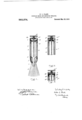
The various features of my invention as preferably constructed when applied to or adapted for use in connection with a fountain shaving brush are illustrated in the accompanying drawings, in which-- Figure 1 is a central longitudinal section through one form of brush, complete; Fig. 2 is a similar section through the outer end of the handle portion of another form of brush; and Fig. 3 is a similar section showin another construction.
he shaving brush illustrated in Fig. 1 of the drawings comprises a body portion 2 carrying a mass of bristles 3', and provided with a hollow handle 4 having a removable portion such as a cap 5 telescopically fitted to the outer end of said handle, although the entire handle may be (letachably connected-to the body of the brush as at 6.
7 represents a detachable soap receptacle adapted to'be inserted into and withdrawn from the hollow handle and provided with; an elongated neck or outlet nozzle 8 or ranged to )roject through a central opening in the body portion 2 and into the interior of the mass of bristles 3. This re ce fuels 7 is provided with a piston 9 origina 1y located at the rear or outer end of said receptacle, behind the material contained therein, and for forcing said piston rod 10 passing through said piston and through a cap 11 closin the outer end of the receptacle, and exten in longitudinally within the latter in threa ed engagement with the piston.
The parts above described are similar in construction and arrangement to the corresponding parts shown and described in a prior application for U. S. Letters Patent filed by me on the 13th day of November, 1906, Serial No. 343,273, in which certain features of the aforesaid constructon are claimed. In said prior application, however, the threaded rod is shown as having a bearing on the interior of the cap which closes the outer end of the receptacle. so that if said rod be rotated in the proper direction the piston will be forced forward by reason of its screw-threaded enga emeut therewith, while in the present case t e rod 10 has no hearing on the cap piece 11 but passes freely through the same, its outer en being provided or engaged with a suitable operating head. As shown in Fig. 1 a thumb piece 12 is provided, which is mounted to rotate in thecap 5 and has a socket adapted to receive and fit the squared outer end of the rod 10, from which it can thus be readily detached whenever it is desired to disconnect the cap 5 from the handle 4 and the receptacle. The lluunb piece 12, in addition to being rotutuhlv mounted in the cap 5, is also capable of a reciprocating movement with respect to the some in the direction in which the threaded rod 10 extends, said movement being preferably-limited by suitable stops.
In the construction illustrated the head 13 of the thumb icce itself serves as the stop for limiting tie inward or forward move ment of said thumb piece. while the stop for limiting, the movement of the same in the .opposite direction. is afiorded by a disk or flange 14 curried bythe inner end of said thumb pii'ce. in posit ion to abut against the adjacent face of the cup 5. is thus constructed, by turning the thumb piece 12 in (,the proper direction the rod 10 may be rotated and caused to travel outward or back ward through the piston, without moving the latter, until the flange 14 abuts against the cap 5, whereu )on by pressing said thumb piece inward wit iout rotating it the piston will he forced forward by its engagement withsaid rod 10 through a distance correspending to the movement of said thumb iecc, which distance cannot exceed the ength of the reduced portion of the thumb piece between its head 13 and flange 14. My construction thus provides for determining with accuracy the distance through which the piston is to be forced forward in any given instance, and therefore the quantity of soap or other material which will be expelled from the rece tacle by such movement,a result whicli is particularly advantageous in cases where the amount of material so expelled cannctbe directly observed, as is the case in fountain brushes of the type illustrated. My arrangen'ient may obviously be used to expel with equal accuracy any less amount of material than that resulting from a maximum movement of the thumb piece, provided the latter be not withdrawn by rotation to its outermost position, and it may also be noted that the piston may be operated, if desired, by merel rotating the thumb piece 12, if said thumg piece be held against longitudinal movement.
Those features of my invention which relate more particularly to the sim lification of the receptacle or reservoir ,itsel are illus trated in Fig. 2, in which is shown a receptacle 7 having no permanent cap for closing its outer end but adapted to have its piston-operating means inserted when the receptac e and the brush proper are assembled for use. The piston is represented in this figure as composed of two parts, namely, a disk 15 of cork or the like, which makes a close sliding fit with the interior of the receptacle, and a metallic disk 16 of slightly less diameter than the disk 15 and adapted to serve as a reinforcing and strengthening backing for the later, as well as for forcing it forward. The two disks 15 and 16 are preferably separable, in which case the operating rod 10' has a screw-threaded en agcment with the disk 16 and passes fi'eely through a central perforation in the disk 15, the former disk being provided with rojections or teeth 17 adapted to be forced into the cork disk 15 and prevent relative rotation of the two disks. I This arrangement permits the rece tacle 7, when first filled with its intende contents, to be closed by inserting the cork disk 15 into its outer end and cover n said disk with a sheetaof tin foil or simil a to revent any of the contents ofthe receptac e from passing out through the central perforation in the disk, thus providing a package which may be put up and sold irrespective of the threaded rod 10' and the disk 16. In this case said parts 10' and 16 will be sold in connection with the brush proper and combined successively with a niimber of filled receptacles, the combination being effected by inserting one of the receptacles into the hollow handle of the brush,
1' material in such manner as.
forcing the threaded rod 10' throu h the central perforation in the cork dis and causing the rigid disk 16 to seat a ainst'the rear or outer face of said cork dis and inasmuch as the rod 10 and disk 16 are detachable from the receptacle and its cork disk, said rod may or may not be detachable from the means for operating it, which means are represented in Fig. 2 as consistmg of a rotatable and longitudinally-movable thumb piece 12 mounted to o eragte in the detachable cap 5 which nor-ma ly closes the outer end of the brush handle, substantially as shown in Fig. 1. My invention thus makes it possible to provide each brush proper with PISbOIl-OPQIEtlHgHIGHIIS capable of serving as such in connection with an number of receptacles adapted fornse wit the brush, and to make and sell such receptacles without anypiston-o crating means, thereby reducing the cost 0 the race tacles and contributing to the possibility ,0 ;'providing filled receptacles at such a low price that the use of the brush will be reasonably economical for the avera e user.
It will be' evident that -t e means for operating. the piston of a receptacle-such as is shown in Fig. 2 may be detachably connected to the receptacle itself, if desired, and such an. arrangement is illustrated in Fig.- 3, in which the receptacle 7' has the cap 5 slipped directly upon its outer end, in fric tional engagement therewith, said cap being preferably rovided with longitudinal slits 18 to enab e it to expand sli htly when forced upon the receptacle and thus increase its grip ihpon the same. The threaded rod 10, the isk 16 carried thereby, and the operatin thumb piece 12 are constructed andcom ined in the same manner as is illustrated in Fig. 2, the thumb iec'e being mounted in the cap 5" and the disk 16, bein arranged to engage and operate the cork dis r 15 by which the receptacle is closed when first filled. I thus provide a reservoir or receptacle which may be sold without any is ton-operating means, as above described,- at
which when combined with a cap 5" and connected parts will form a complete and operative package from which'the contents may be expelled at will, and which may beused either in connection with a fountain brush or independently thereof. If used with such a brush it may be detachably con- ,nected thereto in any suitable manner, as,
for example, by surrounding the cap 5" with a ring 19 of soft rubber or similar ma terial adapted to enter the hollow handle portion 4 of the brush and fit the same with suflicient closeness to hold the receptacle in piece 12 will serve as a sort of coyer for the 0 en end of the brush handle.
. ,1 0 aim as my invention:
1. In a fountain brush, the combination place, in which case the head of the thumb with a body portion and bristles of a hollow handle portion, a receptacle removably contained t erein and provided at its inner end with an outlet, a piston arranged to slide longitudinally in. said receptacle, and a with the body portion and bristles of a h0llow handle portion, a receptacle removably contained therein and provided at its inner end with an outlet, a piston adapted to slide longitudinallylin said receptacle, a threaded rod passing t rough and en aging said piston and also passing throu 1 the outer end of the receptacle, said rod being movable in an endwise direction,'without rotation, when the combined parts are in assembled position, and means for limiting the ndwise o r non-rotative movement of said rod.
3. In a fountain brush the combination with the body portion and bristles of a hollow handle comprising a removable portion, a receptacle removably contained within said hollow handle and provided at its inner end with an outlet, a piston adapted to slide longitudinally in said receptacle, a threaded rod passing through and engagin said pis ton and also passin freel throug theouter end of the receptac e, an an operating head mounted to rotate and to reciprocate without rotation in the removable handle portion and operatively engaging said rod.
Lin a fountain brush, the combination with the body portion and bristles of a hollow handle comprising a removable A ortion, a receptacle removably contained wit in said hollow handle and provided at its inner end with an outlet, a iston adapted to slide longitudinally in said receptacle, a threaded rod passin through and engaging said piston and a so passing freely through the outer end of the receptacle, an o crating head mounted to rotate and to reciprocate without rotation in the removable handle portion and operatively engaging said 'rod, and means for limiting the reciprocating movement of said operating head.
3. In a fountain brush. the combination with the' iody portion and bristles of a hollow handle carricd by said body ortionand comprising a cap piece detacha 1y applied to its outer end. a receptacle'removably contained within said hollow handle andhavin an outlet at its inner end, a piston adapter to slide longitudinally in said receptacle, and a threaded rod passing through and engaging said pi ton, aid rod being movable in an udw e (Lot on *l-rough the outer t of the latter wit 'end of the receptacle, without rotation, and being provided at its outer end with operating means passing through the cap piece and o rable from the exterior thereof.
6. n a fountain brush, the combination with the body portions and bristles of a hollow handle portion and a receptacle removably contained therein, said receptacle being provided with an outlet at its inner end and with a piston adapted to slide longitudinally within the receptacle, a threaded rod passing through and on aging said piston and also passing throug the outer end of the receptacle, sa1d' rod being movable in an endwise direction, without rotation, when the combined parts are in assembled position, and being lprovided at its outer end with an operating ead or thumb piece, and means for limiting the endwise or non-rotative movement of said rod.
7. In a fountain brush, the combination with the body portion and bristles of a hollow handle portion'and a receptacle removably contained therein and provided at its inner end with an outlet, a piston ada ted to slide lon itudinally in said receptac e, a threaded rod passing through and engaging said iston, said rod being movable in an endwise direction without rotation, a thumb I iece for o crating said rod, and a ca piece ocated at t e outer end of the hollow andle portion and having said thumb piece passing thron h it.
8. n a fountain brush, the combination with the body portion and bristles of a hollow handle portion and a receptacle removably contained therein and having an outlet at its inner end, a piston adapted to slide longitudinally in said receptacle and comprising two separable portions. and a rod passing through said piston in threaded en agement therewith, said rod being mov' ab e through. the outer end of the receptacle I in an endwise direction, without rotation when the combined parts are in assembled osition, and being provided on the exterior of the latter with operating means.
9. [n a fountain brush, the combination with the body portion and bristles of a hollow handle portion and a receptacle removably contained therein and having an outlet at its inner end, a piston adapted to slide longitudinally in said receptacle and comprising two separable portions, a rod passing through said'piston in threaded enga ement therewith; said rod being movab e through the outer'end of the receptacle in an endwisedii'ection, without rotation, when the combined parts are in assembled position, and bein provided on the exterior operating means, and means for: limiting the endwise movement of said rod.
10. As an article of manufacture, a brush comprising a body portion and bristles and In testimony whereof, I have hereunto subscribed my :name this twenty-third day M l of January, 907.
WVALTER L. CLARK. \Vitnesses:
E. D. CHADWICK,
JOSEPH T. BRENNAN.
Priority Applications (1)
| Application Number | Priority Date | Filing Date | Title |
|---|---|---|---|
| US35418407A US953374A (en) | 1907-01-26 | 1907-01-26 | Fountain-brush and reservoir therefor. |
Applications Claiming Priority (1)
| Application Number | Priority Date | Filing Date | Title |
|---|---|---|---|
| US35418407A US953374A (en) | 1907-01-26 | 1907-01-26 | Fountain-brush and reservoir therefor. |
Publications (1)
| Publication Number | Publication Date |
|---|---|
| US953374A true US953374A (en) | 1910-03-29 |
Family
ID=3021782
Family Applications (1)
| Application Number | Title | Priority Date | Filing Date |
|---|---|---|---|
| US35418407A Expired - Lifetime US953374A (en) | 1907-01-26 | 1907-01-26 | Fountain-brush and reservoir therefor. |
Country Status (1)
| Country | Link |
|---|---|
| US (1) | US953374A (en) |
Cited By (3)
| Publication number | Priority date | Publication date | Assignee | Title |
|---|---|---|---|---|
| US3802023A (en) * | 1971-12-06 | 1974-04-09 | Spatz Corp | Brush |
| US4699161A (en) * | 1986-05-12 | 1987-10-13 | Louise Smith | Nail polish remover wand |
| US4854761A (en) * | 1987-11-20 | 1989-08-08 | Louise Smith | Nail polish remover wand containing disposable pads |
-
1907
- 1907-01-26 US US35418407A patent/US953374A/en not_active Expired - Lifetime
Cited By (4)
| Publication number | Priority date | Publication date | Assignee | Title |
|---|---|---|---|---|
| US3802023A (en) * | 1971-12-06 | 1974-04-09 | Spatz Corp | Brush |
| US4699161A (en) * | 1986-05-12 | 1987-10-13 | Louise Smith | Nail polish remover wand |
| US4854761A (en) * | 1987-11-20 | 1989-08-08 | Louise Smith | Nail polish remover wand containing disposable pads |
| US4884913A (en) * | 1987-11-20 | 1989-12-05 | Louise Smith | Nail polish remover wand containing disposable pads |
Similar Documents
| Publication | Publication Date | Title |
|---|---|---|
| US6945256B2 (en) | Folding toothbrush with paste in handle | |
| US6009886A (en) | Dentifrice and floss dispensing toothbrush | |
| US4693622A (en) | Combined toothbrush and toothpaste dispenser | |
| US4949875A (en) | Dispenser with integrated cover for paste-like material | |
| US10858170B2 (en) | Dual dispensing cosmetic container | |
| US3193863A (en) | Paint brush construction | |
| US3728035A (en) | Plastic fountain toothbrush | |
| US1909146A (en) | Combination shaving brush and soap container | |
| US2849737A (en) | Lather applicator | |
| US3741667A (en) | Tooth brush complete with dispenser for the tooth paste | |
| US3383157A (en) | Dispensing utensil | |
| GB989954A (en) | Improvements in or relating to toothbrushes | |
| US1309900A (en) | Fountain bbush | |
| US2632904A (en) | Fountain brush with sele-closing outlet tube | |
| US4288169A (en) | Fountain tooth brush with snap-on closure | |
| US954133A (en) | Fountain-brush. | |
| US1499784A (en) | Lip-stick holder | |
| US3339810A (en) | Dispensing apparatus | |
| US2349726A (en) | Dispenser for extrusile substances | |
| US965309A (en) | Fountain tooth-brush. | |
| US2537872A (en) | Valve for fountain stencil brush | |
| US809419A (en) | Dispensing device. | |
| US1395302A (en) | Dispensing device | |
| US953372A (en) | Fountain-brush. | |
| JPH0742537Y2 (en) | Applicator |