US9533545B2 - Thermal management system for an electric vehicle - Google Patents
Thermal management system for an electric vehicle Download PDFInfo
- Publication number
- US9533545B2 US9533545B2 US14/141,585 US201314141585A US9533545B2 US 9533545 B2 US9533545 B2 US 9533545B2 US 201314141585 A US201314141585 A US 201314141585A US 9533545 B2 US9533545 B2 US 9533545B2
- Authority
- US
- United States
- Prior art keywords
- heat
- dynamic
- main
- unit
- heat dissipating
- Prior art date
- Legal status (The legal status is an assumption and is not a legal conclusion. Google has not performed a legal analysis and makes no representation as to the accuracy of the status listed.)
- Active, expires
Links
Images


Classifications
-
- B—PERFORMING OPERATIONS; TRANSPORTING
- B60—VEHICLES IN GENERAL
- B60H—ARRANGEMENTS OF HEATING, COOLING, VENTILATING OR OTHER AIR-TREATING DEVICES SPECIALLY ADAPTED FOR PASSENGER OR GOODS SPACES OF VEHICLES
- B60H1/00—Heating, cooling or ventilating [HVAC] devices
- B60H1/00357—Air-conditioning arrangements specially adapted for particular vehicles
- B60H1/00385—Air-conditioning arrangements specially adapted for particular vehicles for vehicles having an electrical drive, e.g. hybrid or fuel cell
- B60H1/00392—Air-conditioning arrangements specially adapted for particular vehicles for vehicles having an electrical drive, e.g. hybrid or fuel cell for electric vehicles having only electric drive means
-
- B—PERFORMING OPERATIONS; TRANSPORTING
- B60—VEHICLES IN GENERAL
- B60H—ARRANGEMENTS OF HEATING, COOLING, VENTILATING OR OTHER AIR-TREATING DEVICES SPECIALLY ADAPTED FOR PASSENGER OR GOODS SPACES OF VEHICLES
- B60H1/00—Heating, cooling or ventilating [HVAC] devices
- B60H1/00642—Control systems or circuits; Control members or indication devices for heating, cooling or ventilating devices
- B60H1/00814—Control systems or circuits characterised by their output, for controlling particular components of the heating, cooling or ventilating installation
- B60H1/00878—Control systems or circuits characterised by their output, for controlling particular components of the heating, cooling or ventilating installation the components being temperature regulating devices
- B60H1/00899—Controlling the flow of liquid in a heat pump system
- B60H1/00907—Controlling the flow of liquid in a heat pump system where the flow direction of the refrigerant changes and an evaporator becomes condenser
-
- B—PERFORMING OPERATIONS; TRANSPORTING
- B60—VEHICLES IN GENERAL
- B60H—ARRANGEMENTS OF HEATING, COOLING, VENTILATING OR OTHER AIR-TREATING DEVICES SPECIALLY ADAPTED FOR PASSENGER OR GOODS SPACES OF VEHICLES
- B60H1/00—Heating, cooling or ventilating [HVAC] devices
- B60H1/02—Heating, cooling or ventilating [HVAC] devices the heat being derived from the propulsion plant
- B60H1/04—Heating, cooling or ventilating [HVAC] devices the heat being derived from the propulsion plant from cooling liquid of the plant
- B60H1/08—Heating, cooling or ventilating [HVAC] devices the heat being derived from the propulsion plant from cooling liquid of the plant from other radiator than main radiator
-
- B—PERFORMING OPERATIONS; TRANSPORTING
- B60—VEHICLES IN GENERAL
- B60H—ARRANGEMENTS OF HEATING, COOLING, VENTILATING OR OTHER AIR-TREATING DEVICES SPECIALLY ADAPTED FOR PASSENGER OR GOODS SPACES OF VEHICLES
- B60H1/00—Heating, cooling or ventilating [HVAC] devices
- B60H1/32—Cooling devices
- B60H1/3204—Cooling devices using compression
- B60H1/3205—Control means therefor
- B60H1/3213—Control means therefor for increasing the efficiency in a vehicle heat pump
-
- F—MECHANICAL ENGINEERING; LIGHTING; HEATING; WEAPONS; BLASTING
- F25—REFRIGERATION OR COOLING; COMBINED HEATING AND REFRIGERATION SYSTEMS; HEAT PUMP SYSTEMS; MANUFACTURE OR STORAGE OF ICE; LIQUEFACTION SOLIDIFICATION OF GASES
- F25B—REFRIGERATION MACHINES, PLANTS OR SYSTEMS; COMBINED HEATING AND REFRIGERATION SYSTEMS; HEAT PUMP SYSTEMS
- F25B49/00—Arrangement or mounting of control or safety devices
- F25B49/02—Arrangement or mounting of control or safety devices for compression type machines, plants or systems
-
- F—MECHANICAL ENGINEERING; LIGHTING; HEATING; WEAPONS; BLASTING
- F25—REFRIGERATION OR COOLING; COMBINED HEATING AND REFRIGERATION SYSTEMS; HEAT PUMP SYSTEMS; MANUFACTURE OR STORAGE OF ICE; LIQUEFACTION SOLIDIFICATION OF GASES
- F25B—REFRIGERATION MACHINES, PLANTS OR SYSTEMS; COMBINED HEATING AND REFRIGERATION SYSTEMS; HEAT PUMP SYSTEMS
- F25B13/00—Compression machines, plants or systems, with reversible cycle
-
- F—MECHANICAL ENGINEERING; LIGHTING; HEATING; WEAPONS; BLASTING
- F25—REFRIGERATION OR COOLING; COMBINED HEATING AND REFRIGERATION SYSTEMS; HEAT PUMP SYSTEMS; MANUFACTURE OR STORAGE OF ICE; LIQUEFACTION SOLIDIFICATION OF GASES
- F25B—REFRIGERATION MACHINES, PLANTS OR SYSTEMS; COMBINED HEATING AND REFRIGERATION SYSTEMS; HEAT PUMP SYSTEMS
- F25B2313/00—Compression machines, plants or systems with reversible cycle not otherwise provided for
- F25B2313/003—Indoor unit with water as a heat sink or heat source
-
- F—MECHANICAL ENGINEERING; LIGHTING; HEATING; WEAPONS; BLASTING
- F25—REFRIGERATION OR COOLING; COMBINED HEATING AND REFRIGERATION SYSTEMS; HEAT PUMP SYSTEMS; MANUFACTURE OR STORAGE OF ICE; LIQUEFACTION SOLIDIFICATION OF GASES
- F25B—REFRIGERATION MACHINES, PLANTS OR SYSTEMS; COMBINED HEATING AND REFRIGERATION SYSTEMS; HEAT PUMP SYSTEMS
- F25B2313/00—Compression machines, plants or systems with reversible cycle not otherwise provided for
- F25B2313/023—Compression machines, plants or systems with reversible cycle not otherwise provided for using multiple indoor units
- F25B2313/0234—Compression machines, plants or systems with reversible cycle not otherwise provided for using multiple indoor units in series arrangements
-
- F—MECHANICAL ENGINEERING; LIGHTING; HEATING; WEAPONS; BLASTING
- F25—REFRIGERATION OR COOLING; COMBINED HEATING AND REFRIGERATION SYSTEMS; HEAT PUMP SYSTEMS; MANUFACTURE OR STORAGE OF ICE; LIQUEFACTION SOLIDIFICATION OF GASES
- F25B—REFRIGERATION MACHINES, PLANTS OR SYSTEMS; COMBINED HEATING AND REFRIGERATION SYSTEMS; HEAT PUMP SYSTEMS
- F25B25/00—Machines, plants or systems, using a combination of modes of operation covered by two or more of the groups F25B1/00 - F25B23/00
- F25B25/005—Machines, plants or systems, using a combination of modes of operation covered by two or more of the groups F25B1/00 - F25B23/00 using primary and secondary systems
-
- F—MECHANICAL ENGINEERING; LIGHTING; HEATING; WEAPONS; BLASTING
- F25—REFRIGERATION OR COOLING; COMBINED HEATING AND REFRIGERATION SYSTEMS; HEAT PUMP SYSTEMS; MANUFACTURE OR STORAGE OF ICE; LIQUEFACTION SOLIDIFICATION OF GASES
- F25B—REFRIGERATION MACHINES, PLANTS OR SYSTEMS; COMBINED HEATING AND REFRIGERATION SYSTEMS; HEAT PUMP SYSTEMS
- F25B2600/00—Control issues
- F25B2600/13—Pump speed control
Definitions
- This invention relates to a thermal management system, and more particularly to a thermal management system for an electric vehicle.
- Heat energy of an electric vehicle needs to be managed to avoid heat accumulation which easily causes damage to the components of the vehicle due to overheat, and to transfer heat of an air conditioner installed within the vehicle. Hence, it is desirable to distribute and manage effectively heat energy during running of an electric vehicle.
- the object of this invention is to provide an electric vehicle thermal management system that can improve heat distribution and management.
- an electric vehicle thermal management system includes a dynamic heat dissipating unit, an air conditioner unit, a heat exchange unit, and a control unit.
- the dynamic heat dissipating unit includes a coolant circulation pipeline adapted for permitting a coolant to flow and circulate therein along a coolant circulation direction, a main heat dissipating device connected to the coolant circulation pipeline, a liquid pump connected to the coolant circulation pipeline and disposed downstream of the main heat dissipating device along the coolant circulation direction, and a dynamic device connected to the coolant circulation pipeline and disposed downstream of the liquid pump along the coolant circulation direction.
- the main heat dissipating device is adapted for dissipating heat from the coolant flowing therethrough.
- the liquid pump controls a flow rate of the coolant flowing therethrough.
- the dynamic device is adapted to generate a power and heat.
- the air conditioner unit is convertible between a cooling mode and a heating mode, and includes a refrigerant circulation pipeline adapted for permitting a refrigerant to circulate therein in a selected one of a cooling circulation direction and a heating circulation direction that are opposite to each other, a vehicle external heat exchanging device connected to the refrigerant circulation pipeline, an expansion valve connected to the refrigerant circulation pipeline and disposed downstream of the vehicle external heat exchanging device along the cooling circulation direction, a vehicle evaporator connected to the refrigerant circulation pipeline and disposed downstream of the expansion valve along the cooling circulation direction, and a compressor device connected to the refrigerant circulation pipeline and disposed downstream of the vehicle evaporator.
- the refrigerant circulates along the cooling circulation direction during the cooling mode of the air conditioner unit, and along the heating circulation direction during the heating mode of the air conditioner unit.
- the heat exchange unit is connected to the coolant circulation pipeline and the refrigerant circulation pipeline, and is disposed in a coolant inlet of the main heat dissipating device of the dynamic heat dissipating unit and a refrigerant circulation outlet of the compressor of the air conditioner unit such that, during the cooling mode of the air conditioner unit, heat is transmitted from the air conditioner unit to the dynamic heat dissipating unit, and is dissipated through the main heat dissipating device.
- the control unit is electrically connected to the liquid pump, and emits a control signal to the liquid pump.
- the liquid pump is operable to adjust the flow rate of the coolant flowing therethrough in accordance with the control signal.
- heat can be transferred between the dynamic heat dissipating unit and the air conditioner unit through the heat exchange unit, and the flow rate of the coolant can be adjusted under control of the control unit, so as to control heat transfer in the system, thereby improving heat distribution and management in the system.
- FIG. 1 is a schematic diagram of the first preferred embodiment of a thermal management system for an electric vehicle according to this invention
- FIG. 2 is a schematic diagram of the first preferred embodiment, illustrating a dynamic heat dissipating mode of a dynamic heat dissipating unit
- FIG. 3 is a schematic diagram of the first preferred embodiment, illustrating a heat dissipation assisting mode of the dynamic heat dissipating unit
- FIG. 4 is a Mollier chart illustrating a heat circulation curve during a cooling mode of an air conditioner unit of the first preferred embodiment
- FIG. 5 is a schematic diagram illustrating a thermal management control of the first preferred embodiment
- FIG. 6 is a schematic diagram of the first preferred embodiment, illustrating a start activation mode of the dynamic heat dissipating unit
- FIG. 7 is a schematic diagram of the first preferred embodiment, illustrating a dual heating mode of the dynamic heat dissipating unit
- FIG. 8 is a schematic diagram of the first preferred embodiment, illustrating a heat recovering mode of the dynamic heat dissipating unit
- FIG. 9 is a Mollier chart illustrating a heat circulation curve during a heating mode of the air conditioner unit of the first preferred embodiment
- FIG. 10 is a schematic diagram illustrating a modification to the dynamic heat dissipating unit of the first preferred embodiment
- FIG. 11 is a schematic diagram illustrating an auxiliary circulation device of the first preferred embodiment
- FIG. 12 is a schematic diagram of the second preferred embodiment of a thermal management system for an electric vehicle according to this invention.
- FIG. 13 is a schematic diagram of the second preferred embodiment, illustrating operation of a heat exchange four-way valve.
- FIG. 14 is a Mollier chart illustrating function of the heat exchange four-way valve of the second preferred embodiment.
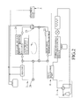
- the first thermal management system for an electric vehicle includes a dynamic heat dissipating unit 2 , an air conditioner unit 3 , a heat exchange unit 4 , and a control unit 5 .
- the dynamic heat dissipating unit 2 includes a dynamic coolant circulation pipeline 21 permitting flow of a coolant therein, a main heat dissipating device 22 connected to the dynamic coolant circulation pipeline 21 , a liquid pump 23 , a dynamic device 24 , an auxiliary heating device 25 , an auxiliary circulation device 26 , and three temperature sensors 27 connected to the control unit 5 .
- the main heat dissipating device 22 is disposed for dissipating heat from the coolant.
- the liquid pump 23 is disposed for controlling the flow rate of the coolant.
- the dynamic device 24 is disposed for producing power and heat energy.
- the dynamic device 24 includes a main battery 241 , a motor 242 , and a plurality of electronic equipments 243 (only one is shown in FIG. 1 ).
- the auxiliary heating device 25 includes a heater 251 connected to the dynamic coolant circulation pipeline 21 and located between the heat exchange unit 4 and the dynamic device 24 , and a spare battery 252 electrically connected to the heater 251 and the liquid pump 23 .
- the auxiliary circulation device 26 is in fluid communication with a juncture between the dynamic device 24 and the heater 251 , a juncture between the heater 251 and the heat exchange unit 4 , a juncture between the heat exchange unit 4 and the main heat dissipating device 22 , and a juncture between the main heat dissipating device 22 and the liquid pump 23 .
- the auxiliary circulation device 26 is operable to change the circulation path of the coolant so as to switch the dynamic heat dissipating unit 2 among five operating modes including a dynamic heat dissipating mode, a heat dissipation assisting mode, a start activation mode, a dual heating mode, and a heat recovering mode.
- the auxiliary circulation device 26 is connected to the dynamic coolant circulation pipeline 21 , and includes a first main three-way valve 261 , a second main three-way valve 262 , a third main three-way valve 263 , and a fourth main three-way valve 264 .
- the first main three-way valve 261 is disposed between the dynamic device 24 and the heater 251 .
- the second main three-way valve 263 is disposed between the heater 251 and the heat exchange unit 4 .
- the third main three-way valve 263 is disposed between the heat exchange unit 4 and the main heat dissipating device 22 .
- the fourth main three-way valve 264 is disposed between the main heat dissipating device 22 and the liquid pump 23 .
- the auxiliary circulation device 26 further includes a first auxiliary three-way valve 265 , a second auxiliary three-way valve 266 , and five auxiliary pipes 267 .
- the first auxiliary three-way valve 265 is in fluid communication with the first main three-way valve 261 and the second three-way valve 262 via two auxiliary circulation pipes 267 , respectively.
- the second auxiliary three-way valve 266 is in fluid communication with the first auxiliary three-way valve 265 , the third main three-way valve 263 , and the fourth main three-way valve 264 via the remaining three auxiliary circulation pipes 267 , respectively.
- the temperature sensors 27 are disposed for measuring respectively the temperatures of coolant inlet and outlet of the dynamic device 24 and a coolant inlet of the main heat dissipating device 22 to emit temperature signals to the control unit 5 .
- the air conditioner unit 3 is convertible between a cooling mode and a heating mode, and includes a refrigerant circulation pipeline 31 permitting a refrigerant to flow therein along a cooling circulation direction or a heating circulation direction, a vehicle external heat exchanging device 32 connected to the refrigerant circulation pipeline 31 , an expansion valve 33 , a vehicle internal heat exchanging device 34 , and a compressor device 35 .
- the vehicle external heat exchanging device 32 includes a plurality of heat dissipating fins 321 and a fan 322 .
- the vehicle internal heat exchanging device 34 is configured as a plurality of heat dissipating fins.
- the compressor device 35 includes a compressor 351 and a four-way valve 352 .
- the four-way valve 352 is operable to change a manner in which the compressor 351 and the refrigerant circular pipeline 31 are interconnected, so as to change the circulating direction of the refrigerant.
- the refrigerant circulates along the cool air circulation direction.
- the air conditioner unit 3 operates in the heating mode, the refrigerant circulates along the heating circulation direction.
- the heat exchange unit 4 is connected to the dynamic coolant circulation pipeline 21 and the refrigerant circulation pipeline 31 , and has three portions that are disposed respectively in the coolant inlet of the main heat dissipating device 22 of the dynamic heat dissipating unit 2 , the cooling circulation direction outlet of the compressor device 35 of the air conditioner unit 3 , and a heating circulation direction inlet of the compressor device 35 of the air conditioner unit 3 .
- the heat exchange unit 4 is disposed for transmitting heat from the air conditioner unit 3 to the main heat dissipating device 22 of the dynamic heat dissipating unit 2 when in the cooling mode, and for transmitting heat from the dynamic heat dissipating unit 2 to the air conditioner unit 3 when in the heating mode.
- the control unit 5 is electrically connected to the liquid pump 23 , and is capable of outputting control signals.
- the control unit 5 receives and processes the temperature signals to obtain an estimated heat generating value and a heat dissipating ability value of the main heat dissipating device 22 .
- the control unit 5 emits a corresponding control signal to the liquid pump 23 .
- the liquid pump 23 is operated to increase the flow rate until the estimated heat generating value is equal to or smaller than the heat dissipating ability value.
- the air conditioner unit 3 is closed, and the dynamic heat dissipating unit 2 dissipates heat from the dynamic device 24 .
- the auxiliary circulation device 26 is operated to allow the coolant to flow circulatively among the dynamic device 24 , the main heat dissipating device 22 , and the liquid pump 23 .
- Heat of the dynamic device 24 is dissipated by the main heat dissipating device 22 .
- the air conditioner unit 3 is opened, and operates in the cooling mode.
- the dynamic heat dissipating unit 2 dissipates heat from the dynamic device 24 , and facilitates heat dissipation of the air conditioner unit 3 to promote the cooling effect of the air conditioner unit 3 .
- the auxiliary circulation device 26 is operated to allow the coolant to flow circulatively in the dynamic coolant circulation pipeline 21 among the dynamic device 24 , the heat exchanger 4 , the main heat dissipating device 22 , and the liquid pump 23 . In this state, the refrigerant in the refrigerant circulation pipeline 31 circulates in the cooling circulation direction.
- the refrigerant in the refrigerant circulation pipeline 31 flows past the vehicle internal heat exchanging device 34 , so as to dissipate heat from the same to thereby reduce the temperature in the vehicle. Hence, heat is transmitted from the vehicle internal heat exchanging device 34 into the surroundings through the vehicle external heat exchanging device 32 .
- the coolant in the dynamic coolant circulation pipeline 21 flows past the dynamic device 24 so as to dissipate heat from the same.
- the heat dissipated from the dynamic device 24 is received by the heat exchanging unit 4 , and is transmitted into the surroundings through the main heat dissipating device 22 .
- FIG. 4 is a Mollier chart of the refrigerant used in this embodiment.
- line a-b illustrates the compression process of the refrigerant
- line b-b′ illustrates the heat dissipating extent of the dynamic heat dissipating unit 2
- line b′-c illustrates the heat dissipating ability of the vehicle external heat exchanging device 32
- line c-d illustrates the pressure drop and throttle of the refrigerant
- line d-a illustrates the heat absorption ability of the vehicle internal exchanging device 34 .
- the heat transfer loads of the air conditioner unit 3 and the vehicle external heat exchanging device 32 can be reduced, thereby allowing for a reduction in the volume of the vehicle external heat exchanging device 32 .
- the control unit 5 receives and processes the temperature signals emitted from the temperature sensors 27 to obtain an estimated heat generating value of the dynamic device 24 and a heat dissipating ability value of the main heat dissipating device 22 .
- the control unit 5 can adjust the flow rate of the coolant to allow the heat dissipating ability value of the main heat dissipating device 22 to meet the estimated heat generating value to be required, thereby reducing consumption of power, promoting utilization of power, and avoiding an increase in temperature due to poor heat dissipation.
- the dynamic heat dissipating unit 2 is switched to operate in the start activation mode.
- the auxiliary heating device 25 is driven such that the spare battery 252 supplies electricity to the heater 251 and the liquid pump 23 , and the auxiliary circulation device 26 is switched to allow the coolant to flow and circulate among the dynamic device 24 , the heater 251 , and the liquid pump 23 .
- the coolant in the dynamic coolant circulation pipeline 21 flows past the heater 251 so as to receive heat from the heater 251 .
- the heat transmitted from the heater 251 is carried by the coolant into the dynamic device 24 to activate the main battery 241 and preheat the motor 241 and the electronic equipments 243 .
- the auxiliary heating device 25 is deactivated to increase the use efficiency of the spare battery 252 .
- the spare battery 252 is a NIMH battery, which can supply electricity at a low temperature.
- the dynamic heat dissipating unit 2 is switched to operate in the dual heating mode.
- the air conditioner 3 is opened, and operates in the heating mode, and the auxiliary heating device 25 provides heat energy to both the air conditioner unit 3 and the dynamic device 24 to promote the air heating function of the air conditioner unit 3 .
- the auxiliary circulation device 26 By switching the auxiliary circulation device 26 , the coolant in the dynamic coolant circulation pipeline 21 flows and circulates among the dynamic device 24 , the heater 251 , the heat exchange unit 4 , and the liquid pump 23 . At this time, the refrigerant in the refrigerant circulation pipeline 31 circulates along the heating circulation direction.
- the coolant in the dynamic coolant circulation pipeline 21 flows past the heater 251 so as to receive heat supplied by the same.
- the heat is transmitted from the heater 251 to the air conditioner unit 3 and the dynamic device 24 through the heat exchange unit 4 , thereby allowing the dynamic device 24 to operate at a low temperature.
- the refrigerant in the refrigerant circulation pipeline 31 flows past the vehicle external heat exchanging device 32 so as to receive heat energy from the surroundings, subsequently flows past the heat exchange unit 4 so as to receive heat energy supplied by the dynamic heat dissipating unit 2 , and transmits heat energy to the vehicle internal heat exchanging device 34 for increasing the temperature in the vehicle (i.e., providing warm air into the vehicle).
- the dynamic heat dissipating unit 2 is switched to operate in the heat recovering mode.
- the air conditioner unit 3 is opened, and operates in the heating mode.
- Heat energy generated by the dynamic device 24 is transmitted to the air conditioner unit 3 through the heat exchanger unit 4 so as to promote the air heating function of the air conditioner unit 3 .
- the auxiliary circulation device 26 By switching the auxiliary circulation device 26 , the coolant in the dynamic coolant circulation pipeline 21 flows and circulates among the dynamic device 24 , the heat exchange unit 4 , and the liquid pump 23 . At this time, the refrigerant in the refrigerant circulation pipeline 31 circulates along the heating circulation direction.
- the coolant in the dynamic coolant circulation pipeline 21 flows past the dynamic device 24 so as to receive heat energy generated from the same.
- the heat energy is transmitted from the dynamic device 24 to the air conditioner unit 3 through the heat exchange unit 4 .
- the refrigerant in the refrigerant circulation pipeline 31 flows past the vehicle external heat exchanging device 32 so as to receive heat energy from the surroundings, subsequently flows past the heat exchange unit 4 so as to receive heat energy supplied by the dynamic heat dissipating unit 2 , and transmits heat energy to the vehicle internal heat exchanging device 34 for increasing the temperature in the vehicle (i.e., providing heat into the vehicle).
- heat dissipated from the dynamic device 24 can be recovered and transmitted to the air conditioner unit 3 , thereby forming a heat recovery circulation to promote utilization of heat energy.
- FIG. 9 is a Mollier chart of the refrigerant in this embodiment.
- curve a-b-c-d illustrates a heat circulation of a conventional system that is not provided with the auxiliary heating device 25 and that cannot recover heat energy
- curve a′-b′-c-d illustrates a heat circulation occurring during the heat recovery mode of the dynamic heat dissipating unit 2 in this embodiment
- curve a′′-b′′-c-d illustrates a heat circulation occurring during the dual heating mode of the dynamic heat dissipating unit 2 in this embodiment
- lines a-b, a′-b′, and a′′-b′′ illustrate refrigerant compression process
- lines b-c, b′-c, b′′-c illustrate transmission of heat energy from the vehicle internal heat exchanging device 34 into the vehicle
- line c-d illustrates a refrigerant pressure drop process
- line d-a, d-a′, and d-a′′ illustrate a process for receiving heat energy from the surroundings or the dynamic heat
- each line d-a, d-a′, d-a′′ is, the more the heat energy received is.
- the longer each line b-c, b′-c, b′′-c is, the more the heat provided into the vehicle is.
- the thermal management system of this invention has the following advantages:
- FIG. 10 shows a modified auxiliary circulation device 26 which further includes an auxiliary four-way valve 268 and four auxiliary pipes 267 .
- the auxiliary four-way valve 268 is in fluid communication with the first, second, third, and fourth main three-way valves 261 , 262 , 263 , 264 through the auxiliary pipes 267 , respectively.
- the temperature sensors 27 are used to measure respectively the temperatures of a coolant outlet of the dynamic device 24 , and coolant inlet and outlet of the main heat dissipating device 22 , and emits temperature signals to the control unit 5 .
- the auxiliary circulation device 26 may be integrated with the liquid pump 23 and the control unit 5 , as shown in FIG. 11 , and is connected to the heater 251 , the dynamic device 24 , the main heat dissipating device 22 , and the heat exchange unit 4 , so as to increase convenience when constructing the system.
- the modified thermal management system can achieve the same object and effect of the first preferred embodiment.
- FIG. 12 shows the second preferred embodiment of a thermal management system for an electric vehicle according to this invention, which is similar to the first preferred embodiment and which differs from the first preferred embodiment in the following.
- the air conditioner unit 3 further includes a heat exchange four-way valve 36 , a cooling mode check valve 37 connected between the expansion valve 33 and the vehicle external heat exchanging device 32 and allowing the coolant to flow therethrough in only the cooling circulation direction, a warm air check valve 38 connected between the expansion valve 33 and the vehicle internal heat exchanging device 34 and allowing the refrigerant to flow therethrough in only the heating circulation direction, and a heat exchanger 39 .
- the heat exchange four-way valve 36 is in fluid communication with two ends of the heat exchange unit 4 , an end of the compressor device 35 connected to the heat exchange unit 4 , and an end of the vehicle external heat exchanging device 32 connected to the heat exchange unit 4 .
- the heat exchange four-way valve 35 is operable to connect one end of the heat exchange unit 4 fluidly to a selected one of the compressor device 35 and the vehicle external heat exchanging device 32 , and connect the other end of the heat exchange unit 4 fluidly to the other of the compressor device 35 and the vehicle external heat exchanging device 32 , such that the flowing direction of the coolant in the heat exchange unit 4 is the same as that of the refrigerant in the heat exchange unit 4 .
- the heat exchanger 39 is disposed in the cooling circulation direction outlet of the vehicle external heat exchanging device 32 and the cooling circulation direction outlet of the vehicle internal heat exchanging device 34 , such that heat is transferred from the vehicle external heat exchanging device 32 to the vehicle internal heat exchanging device 34 .
- FIG. 13 illustrates that the air conditioner unit 3 operates in the heating mode.
- the refrigerant flows through the heating mode check valve 38 , and does not flow through the heat exchanger 39 . Since the operation principle of this embodiment is similar to that of the first embodiment, a further description thereof is omitted.
- FIG. 14 is a Mollier chart of the refrigerant in this embodiment.
- the phantom lines a-b and c-d illustrate respectively the refrigerant compression process and the refrigerant pressure drop and throttle process when the heat exchanger 39 is not used
- the solid lines a-b and c-d illustrate respectively the refrigerant compression process and the coolant pressure drop and throttle process when the exchanger 39 is used.
- the heat exchanger 39 provides an additional heat exchanging process for reducing the temperature of the refrigerant flowing from the vehicle external heat exchanging device 32 , as shown by the solid line c-d, and for increasing the temperature of the refrigerant flowing from the vehicle internal heat exchanging device 34 , as shown by the solid line a-b.
- the length of the line d-a is increased. That is, the cooling effect is promoted.
- the second preferred embodiment can achieve the same object and effect as the first preferred embodiment, and has the following additional advantages:
- this embodiment is capable of promoting the heat energy utilization of the system, recovering waste heat to reduce power consumption, improving heat energy control, operating normally at an extremely low temperature, and enhancing safety during use.
- the object of this invention is achieved.
Abstract
An electric vehicle thermal management system includes a dynamic heat dissipating unit, an air conditioner unit, a heat exchange unit, and a control unit. The heat exchange unit is connected to the dynamic heat dissipating unit and the air conditioner unit for transferring heat therebetween. The control unit adjusts the flow rate of a coolant in the dynamic heat dissipating unit for controlling and adjusting the heat dissipating ability of the dynamic heat dissipating unit to meet the heat dissipation of the system, thereby improving distribution and management of heat energy in the system.
Description
This application claims priority of Taiwanese Application No. 102140281, filed on Nov. 6, 2013.
1. Field of the Invention
This invention relates to a thermal management system, and more particularly to a thermal management system for an electric vehicle.
2. Description of the Related Art
Heat energy of an electric vehicle needs to be managed to avoid heat accumulation which easily causes damage to the components of the vehicle due to overheat, and to transfer heat of an air conditioner installed within the vehicle. Hence, it is desirable to distribute and manage effectively heat energy during running of an electric vehicle.
The object of this invention is to provide an electric vehicle thermal management system that can improve heat distribution and management.
According to this invention, an electric vehicle thermal management system includes a dynamic heat dissipating unit, an air conditioner unit, a heat exchange unit, and a control unit.
The dynamic heat dissipating unit includes a coolant circulation pipeline adapted for permitting a coolant to flow and circulate therein along a coolant circulation direction, a main heat dissipating device connected to the coolant circulation pipeline, a liquid pump connected to the coolant circulation pipeline and disposed downstream of the main heat dissipating device along the coolant circulation direction, and a dynamic device connected to the coolant circulation pipeline and disposed downstream of the liquid pump along the coolant circulation direction. The main heat dissipating device is adapted for dissipating heat from the coolant flowing therethrough. The liquid pump controls a flow rate of the coolant flowing therethrough. The dynamic device is adapted to generate a power and heat.
The air conditioner unit is convertible between a cooling mode and a heating mode, and includes a refrigerant circulation pipeline adapted for permitting a refrigerant to circulate therein in a selected one of a cooling circulation direction and a heating circulation direction that are opposite to each other, a vehicle external heat exchanging device connected to the refrigerant circulation pipeline, an expansion valve connected to the refrigerant circulation pipeline and disposed downstream of the vehicle external heat exchanging device along the cooling circulation direction, a vehicle evaporator connected to the refrigerant circulation pipeline and disposed downstream of the expansion valve along the cooling circulation direction, and a compressor device connected to the refrigerant circulation pipeline and disposed downstream of the vehicle evaporator. The refrigerant circulates along the cooling circulation direction during the cooling mode of the air conditioner unit, and along the heating circulation direction during the heating mode of the air conditioner unit.
The heat exchange unit is connected to the coolant circulation pipeline and the refrigerant circulation pipeline, and is disposed in a coolant inlet of the main heat dissipating device of the dynamic heat dissipating unit and a refrigerant circulation outlet of the compressor of the air conditioner unit such that, during the cooling mode of the air conditioner unit, heat is transmitted from the air conditioner unit to the dynamic heat dissipating unit, and is dissipated through the main heat dissipating device.
The control unit is electrically connected to the liquid pump, and emits a control signal to the liquid pump. The liquid pump is operable to adjust the flow rate of the coolant flowing therethrough in accordance with the control signal.
As such, heat can be transferred between the dynamic heat dissipating unit and the air conditioner unit through the heat exchange unit, and the flow rate of the coolant can be adjusted under control of the control unit, so as to control heat transfer in the system, thereby improving heat distribution and management in the system.
These and other features and advantages of this invention will become apparent in the following detailed description of the preferred embodiments of this invention, with reference to the accompanying drawings, in which:
Before the present invention is described in greater detail in connection with the preferred embodiments, it should be noted that similar elements and structures are designated by like reference numerals throughout the entire disclosure.
Referring to FIG. 1 , the first thermal management system for an electric vehicle according to this invention includes a dynamic heat dissipating unit 2, an air conditioner unit 3, a heat exchange unit 4, and a control unit 5.
The dynamic heat dissipating unit 2 includes a dynamic coolant circulation pipeline 21 permitting flow of a coolant therein, a main heat dissipating device 22 connected to the dynamic coolant circulation pipeline 21, a liquid pump 23, a dynamic device 24, an auxiliary heating device 25, an auxiliary circulation device 26, and three temperature sensors 27 connected to the control unit 5.
The main heat dissipating device 22 is disposed for dissipating heat from the coolant. The liquid pump 23 is disposed for controlling the flow rate of the coolant. The dynamic device 24 is disposed for producing power and heat energy.
In this embodiment, the dynamic device 24 includes a main battery 241, a motor 242, and a plurality of electronic equipments 243 (only one is shown in FIG. 1 ).
The auxiliary heating device 25 includes a heater 251 connected to the dynamic coolant circulation pipeline 21 and located between the heat exchange unit 4 and the dynamic device 24, and a spare battery 252 electrically connected to the heater 251 and the liquid pump 23.
The auxiliary circulation device 26 is in fluid communication with a juncture between the dynamic device 24 and the heater 251, a juncture between the heater 251 and the heat exchange unit 4, a juncture between the heat exchange unit 4 and the main heat dissipating device 22, and a juncture between the main heat dissipating device 22 and the liquid pump 23. The auxiliary circulation device 26 is operable to change the circulation path of the coolant so as to switch the dynamic heat dissipating unit 2 among five operating modes including a dynamic heat dissipating mode, a heat dissipation assisting mode, a start activation mode, a dual heating mode, and a heat recovering mode.
The auxiliary circulation device 26 is connected to the dynamic coolant circulation pipeline 21, and includes a first main three-way valve 261, a second main three-way valve 262, a third main three-way valve 263, and a fourth main three-way valve 264. The first main three-way valve 261 is disposed between the dynamic device 24 and the heater 251. The second main three-way valve 263 is disposed between the heater 251 and the heat exchange unit 4. The third main three-way valve 263 is disposed between the heat exchange unit 4 and the main heat dissipating device 22. The fourth main three-way valve 264 is disposed between the main heat dissipating device 22 and the liquid pump 23.
The auxiliary circulation device 26 further includes a first auxiliary three-way valve 265, a second auxiliary three-way valve 266, and five auxiliary pipes 267. The first auxiliary three-way valve 265 is in fluid communication with the first main three-way valve 261 and the second three-way valve 262 via two auxiliary circulation pipes 267, respectively. The second auxiliary three-way valve 266 is in fluid communication with the first auxiliary three-way valve 265, the third main three-way valve 263, and the fourth main three-way valve 264 via the remaining three auxiliary circulation pipes 267, respectively.
The temperature sensors 27 are disposed for measuring respectively the temperatures of coolant inlet and outlet of the dynamic device 24 and a coolant inlet of the main heat dissipating device 22 to emit temperature signals to the control unit 5.
The air conditioner unit 3 is convertible between a cooling mode and a heating mode, and includes a refrigerant circulation pipeline 31 permitting a refrigerant to flow therein along a cooling circulation direction or a heating circulation direction, a vehicle external heat exchanging device 32 connected to the refrigerant circulation pipeline 31, an expansion valve 33, a vehicle internal heat exchanging device 34, and a compressor device 35.
In this embodiment, the vehicle external heat exchanging device 32 includes a plurality of heat dissipating fins 321 and a fan 322. The vehicle internal heat exchanging device 34 is configured as a plurality of heat dissipating fins. The compressor device 35 includes a compressor 351 and a four-way valve 352. The four-way valve 352 is operable to change a manner in which the compressor 351 and the refrigerant circular pipeline 31 are interconnected, so as to change the circulating direction of the refrigerant.
When the air conditioner unit 3 operates in the cooling mode, the refrigerant circulates along the cool air circulation direction. When the air conditioner unit 3 operates in the heating mode, the refrigerant circulates along the heating circulation direction.
The heat exchange unit 4 is connected to the dynamic coolant circulation pipeline 21 and the refrigerant circulation pipeline 31, and has three portions that are disposed respectively in the coolant inlet of the main heat dissipating device 22 of the dynamic heat dissipating unit 2, the cooling circulation direction outlet of the compressor device 35 of the air conditioner unit 3, and a heating circulation direction inlet of the compressor device 35 of the air conditioner unit 3. The heat exchange unit 4 is disposed for transmitting heat from the air conditioner unit 3 to the main heat dissipating device 22 of the dynamic heat dissipating unit 2 when in the cooling mode, and for transmitting heat from the dynamic heat dissipating unit 2 to the air conditioner unit 3 when in the heating mode.
The control unit 5 is electrically connected to the liquid pump 23, and is capable of outputting control signals. The control unit 5 receives and processes the temperature signals to obtain an estimated heat generating value and a heat dissipating ability value of the main heat dissipating device 22. When the estimated heat generating value is greater than the heat dissipating ability value, the control unit 5 emits a corresponding control signal to the liquid pump 23. Hence, the liquid pump 23 is operated to increase the flow rate until the estimated heat generating value is equal to or smaller than the heat dissipating ability value.
The five operating modes of the dynamic heat dissipating unit 2 will be described in the following.
1. Dynamic Heat Dissipating Mode:
Referring to FIG. 2 , the air conditioner unit 3 is closed, and the dynamic heat dissipating unit 2 dissipates heat from the dynamic device 24. The auxiliary circulation device 26 is operated to allow the coolant to flow circulatively among the dynamic device 24, the main heat dissipating device 22, and the liquid pump 23.
Heat of the dynamic device 24 is dissipated by the main heat dissipating device 22.
2. Heat Dissipation Assisting Mode:
Referring to FIG. 3 , the air conditioner unit 3 is opened, and operates in the cooling mode. The dynamic heat dissipating unit 2 dissipates heat from the dynamic device 24, and facilitates heat dissipation of the air conditioner unit 3 to promote the cooling effect of the air conditioner unit 3. The auxiliary circulation device 26 is operated to allow the coolant to flow circulatively in the dynamic coolant circulation pipeline 21 among the dynamic device 24, the heat exchanger 4, the main heat dissipating device 22, and the liquid pump 23. In this state, the refrigerant in the refrigerant circulation pipeline 31 circulates in the cooling circulation direction.
The refrigerant in the refrigerant circulation pipeline 31 flows past the vehicle internal heat exchanging device 34, so as to dissipate heat from the same to thereby reduce the temperature in the vehicle. Hence, heat is transmitted from the vehicle internal heat exchanging device 34 into the surroundings through the vehicle external heat exchanging device 32.
The coolant in the dynamic coolant circulation pipeline 21 flows past the dynamic device 24 so as to dissipate heat from the same. The heat dissipated from the dynamic device 24 is received by the heat exchanging unit 4, and is transmitted into the surroundings through the main heat dissipating device 22.
As shown in FIG. 4 , by dissipating heat from the air conditioner unit 2 through the dynamic heat dissipating unit 2, the heat transfer loads of the air conditioner unit 3 and the vehicle external heat exchanging device 32 can be reduced, thereby allowing for a reduction in the volume of the vehicle external heat exchanging device 32.
With particular reference to FIGS. 3 and 5 , by adjusting the flow rate of the coolant under control of the control unit 5, the thermal management control can be improved. The control unit 5 receives and processes the temperature signals emitted from the temperature sensors 27 to obtain an estimated heat generating value of the dynamic device 24 and a heat dissipating ability value of the main heat dissipating device 22. Since the heat dissipating ability value of the main heat dissipating device 22 is affected by the flow rate of the coolant, and is proportional to the flow rate under the same condition, the control unit 5 can adjust the flow rate of the coolant to allow the heat dissipating ability value of the main heat dissipating device 22 to meet the estimated heat generating value to be required, thereby reducing consumption of power, promoting utilization of power, and avoiding an increase in temperature due to poor heat dissipation.
3. Start Activation Mode:
Referring to FIG. 6 , when the surrounding temperature is less than a start temperature of the dynamic device 24 so that the main battery 241 of the dynamic device 24 cannot be activated or the motor 242 cannot be started, the dynamic heat dissipating unit 2 is switched to operate in the start activation mode. During this mode, the auxiliary heating device 25 is driven such that the spare battery 252 supplies electricity to the heater 251 and the liquid pump 23, and the auxiliary circulation device 26 is switched to allow the coolant to flow and circulate among the dynamic device 24, the heater 251, and the liquid pump 23.
The coolant in the dynamic coolant circulation pipeline 21 flows past the heater 251 so as to receive heat from the heater 251. The heat transmitted from the heater 251 is carried by the coolant into the dynamic device 24 to activate the main battery 241 and preheat the motor 241 and the electronic equipments 243. Upon activation of the main battery 241, the auxiliary heating device 25 is deactivated to increase the use efficiency of the spare battery 252.
It should be noted that, since the auxiliary heating device 25 is required for providing heat energy in cold seasons, and since the spare battery 252 needs to supply electricity to both the heater 251 and the liquid pump 23, in this embodiment, the spare battery 252 is a NIMH battery, which can supply electricity at a low temperature.
4. Dual Heating Mode:
Referring to FIG. 7 , when the weather is cold such that the system cannot work, the dynamic heat dissipating unit 2 is switched to operate in the dual heating mode. During this mode, the air conditioner 3 is opened, and operates in the heating mode, and the auxiliary heating device 25 provides heat energy to both the air conditioner unit 3 and the dynamic device 24 to promote the air heating function of the air conditioner unit 3. By switching the auxiliary circulation device 26, the coolant in the dynamic coolant circulation pipeline 21 flows and circulates among the dynamic device 24, the heater 251, the heat exchange unit 4, and the liquid pump 23. At this time, the refrigerant in the refrigerant circulation pipeline 31 circulates along the heating circulation direction.
The coolant in the dynamic coolant circulation pipeline 21 flows past the heater 251 so as to receive heat supplied by the same. The heat is transmitted from the heater 251 to the air conditioner unit 3 and the dynamic device 24 through the heat exchange unit 4, thereby allowing the dynamic device 24 to operate at a low temperature.
The refrigerant in the refrigerant circulation pipeline 31 flows past the vehicle external heat exchanging device 32 so as to receive heat energy from the surroundings, subsequently flows past the heat exchange unit 4 so as to receive heat energy supplied by the dynamic heat dissipating unit 2, and transmits heat energy to the vehicle internal heat exchanging device 34 for increasing the temperature in the vehicle (i.e., providing warm air into the vehicle).
5. Heat Recovering Mode:
Referring to FIG. 8 , in a situation where the surrounding temperature is low, while the system can operate normally, the dynamic heat dissipating unit 2 is switched to operate in the heat recovering mode. During this mode, the air conditioner unit 3 is opened, and operates in the heating mode. Heat energy generated by the dynamic device 24 is transmitted to the air conditioner unit 3 through the heat exchanger unit 4 so as to promote the air heating function of the air conditioner unit 3. By switching the auxiliary circulation device 26, the coolant in the dynamic coolant circulation pipeline 21 flows and circulates among the dynamic device 24, the heat exchange unit 4, and the liquid pump 23. At this time, the refrigerant in the refrigerant circulation pipeline 31 circulates along the heating circulation direction.
The coolant in the dynamic coolant circulation pipeline 21 flows past the dynamic device 24 so as to receive heat energy generated from the same. The heat energy is transmitted from the dynamic device 24 to the air conditioner unit 3 through the heat exchange unit 4.
The refrigerant in the refrigerant circulation pipeline 31 flows past the vehicle external heat exchanging device 32 so as to receive heat energy from the surroundings, subsequently flows past the heat exchange unit 4 so as to receive heat energy supplied by the dynamic heat dissipating unit 2, and transmits heat energy to the vehicle internal heat exchanging device 34 for increasing the temperature in the vehicle (i.e., providing heat into the vehicle).
Hence, heat dissipated from the dynamic device 24 can be recovered and transmitted to the air conditioner unit 3, thereby forming a heat recovery circulation to promote utilization of heat energy.
The longer each line d-a, d-a′, d-a″ is, the more the heat energy received is. The longer each line b-c, b′-c, b″-c is, the more the heat provided into the vehicle is. Form this chart, the heat energy received and provided into the vehicle by recovering heat energy of the dynamic device 24 and driving the auxiliary heating device 25 can be realized. That is, the air heating function of the air conditioner unit 3 is promoted.
With particular reference to FIG. 1 , in view of the above, the thermal management system of this invention has the following advantages:
- 1. By switching the
auxiliary circulation device 26 to change the circulation path of the coolant in the dynamiccoolant circulation pipeline 21, and by providing a heat exchange path provided by theheat exchange unit 4, during the cooling mode of theair conditioner unit 3, the dynamicheat dissipating unit 2 can facilitate heat dissipation of theair conditioner unit 3 to reduce the load of theair conditioner unit 3 and, thus, the volume of the vehicle externalheat exchanging device 32. During the heating mode of theair conditioner unit 3, heat dissipated from thedynamic device 24 is recovered such that, when the surrounding temperature is extremely low, theauxiliary heating device 25 can be driven to provide additional heat energy, so as to promote the use efficiency of the whole system. Furthermore, waste heat is recovered and reused to reduce energy consumption to thereby meet the environmental protection requirement. - 2. The
control unit 5 receives and processes the temperature signals emitted from thetemperature sensors 27 to obtain the estimated heat generating value and the heat dissipating ability value when the vehicle runs. In this manner, energy utilization can be promoted, and an increase in the temperature due to poor heat dissipation can be avoided. - 3. Due to the presence of the
auxiliary heating device 25 and thespare battery 252, additional heat energy can be provided when the surrounding temperature is low, so as to allow for activation of themain battery 241 and start of themotor 242. Furthermore, when the surrounding temperature is extremely low, theauxiliary heating device 25 can supply heat energy to both thedynamic device 24 and theair conditioner unit 3 so as to allow thedynamic device 24 and theair conditioner unit 3 to operate at the extremely low temperature.
The temperature sensors 27 are used to measure respectively the temperatures of a coolant outlet of the dynamic device 24, and coolant inlet and outlet of the main heat dissipating device 22, and emits temperature signals to the control unit 5.
It should be noted that, in actual use, the auxiliary circulation device 26 may be integrated with the liquid pump 23 and the control unit 5, as shown in FIG. 11 , and is connected to the heater 251, the dynamic device 24, the main heat dissipating device 22, and the heat exchange unit 4, so as to increase convenience when constructing the system.
As such, the modified thermal management system can achieve the same object and effect of the first preferred embodiment.
The air conditioner unit 3 further includes a heat exchange four-way valve 36, a cooling mode check valve 37 connected between the expansion valve 33 and the vehicle external heat exchanging device 32 and allowing the coolant to flow therethrough in only the cooling circulation direction, a warm air check valve 38 connected between the expansion valve 33 and the vehicle internal heat exchanging device 34 and allowing the refrigerant to flow therethrough in only the heating circulation direction, and a heat exchanger 39.
The heat exchange four-way valve 36 is in fluid communication with two ends of the heat exchange unit 4, an end of the compressor device 35 connected to the heat exchange unit 4, and an end of the vehicle external heat exchanging device 32 connected to the heat exchange unit 4. As such, the heat exchange four-way valve 35 is operable to connect one end of the heat exchange unit 4 fluidly to a selected one of the compressor device 35 and the vehicle external heat exchanging device 32, and connect the other end of the heat exchange unit 4 fluidly to the other of the compressor device 35 and the vehicle external heat exchanging device 32, such that the flowing direction of the coolant in the heat exchange unit 4 is the same as that of the refrigerant in the heat exchange unit 4.
The heat exchanger 39 is disposed in the cooling circulation direction outlet of the vehicle external heat exchanging device 32 and the cooling circulation direction outlet of the vehicle internal heat exchanging device 34, such that heat is transferred from the vehicle external heat exchanging device 32 to the vehicle internal heat exchanging device 34.
Hence, the second preferred embodiment can achieve the same object and effect as the first preferred embodiment, and has the following additional advantages:
- 1. Due to the presence of the heat exchange four-
way valve 36, in theheat exchange unit 4, the flowing direction of the coolant in the dynamiccoolant circulation pipeline 21 can be controlled to be the same as that of the refrigerant in therefrigerant circulation pipeline 31, so that the heat exchanging effect of theheat exchange unit 4 provided during the cooling mode of theair conditioner unit 3 is the same as that provided during the heating mode of theair conditioner unit 3. Furthermore, when theheat exchange valve 36 malfunctions, although the performance of the system can be reduced, the system or the user cannot be damaged, thereby ensuring safety during use. - 2. Since the
heat exchanger 39 is disposed in the cooling circulation direction outlets of the vehicle externalheat exchanging device 32 and the vehicle internalheat exchanging device 34, an additional heat exchange process can be provided to further reduce the temperature of the refrigerant flowing from the vehicle externalheat exchanging device 32 to thereby promote the cooling effect of theair conditioner unit 3 and, thus, the operating efficiency of the system.
In view of the above, this embodiment is capable of promoting the heat energy utilization of the system, recovering waste heat to reduce power consumption, improving heat energy control, operating normally at an extremely low temperature, and enhancing safety during use. Thus, the object of this invention is achieved.
With this invention thus explained, it is apparent that numerous modifications and variations can be made without departing from the scope and spirit of this invention. It is therefore intended that this invention be limited only as indicated by the appended claims.
Claims (11)
1. A thermal management system adapted for use in an electric vehicle, said thermal management system comprising:
a dynamic heat dissipating unit including a dynamic coolant circulation pipeline adapted for permitting a coolant to flow and circulate therein along a coolant circulation direction, a main heat dissipating device connected to said dynamic coolant circulation pipeline, a liquid pump connected to said dynamic coolant circulation pipeline and disposed downstream of said main heat dissipating device along the coolant circulation direction, and a dynamic device connected to said dynamic coolant circulation pipeline and disposed downstream of said liquid pump along the coolant circulation direction, said main heat dissipating device being adapted for dissipating heat from the coolant flowing therethrough, said liquid pump controlling a flow rate of the coolant flowing therethrough, said dynamic device being adapted to generate a power and heat;
an air conditioner unit convertible between a cooling mode and a heating mode and including a refrigerant circulation pipeline adapted for permitting a refrigerant to circulate therein in a selected one of a cooling circulation direction and a heating circulation direction that are opposite to each other, a vehicle external heat exchanging device connected to said refrigerant circulation pipeline, an expansion valve connected to said refrigerant circulation pipeline and disposed downstream of said vehicle external heat exchanging device along the cooling circulation direction, a vehicle internal heat exchanging device connected to said refrigerant circulation pipeline and disposed downstream of said expansion valve along the cooling circulation direction, and a compressor device connected to said refrigerant circulation pipeline and disposed downstream of said vehicle internal heat exchanging device along the cooling circulation direction, the refrigerant circulating along the cooling circulation direction during the cooling mode of said air conditioner unit, and along the heating circulation direction during the heating mode of said air conditioner unit;
a heat exchange unit connected to said dynamic coolant circulation pipeline and said refrigerant circulation pipeline and disposed in a coolant inlet of said main heat dissipating device of said dynamic heat dissipating unit and a cooling circulation direction outlet of said compressor device of said air conditioner unit such that, during the cooling mode of said air conditioner unit, heat is transmitted from said air conditioner unit to said dynamic heat dissipating unit, and is dissipated through said main heat dissipating device; and
a control unit electrically connected to said liquid pump and emitting a control signal to said liquid pump, so that said liquid pump is operable to adjust the flow rate of the coolant flowing therethrough in accordance with the control signal.
2. The thermal management system as claimed in claim 1 , wherein said heat exchange unit is disposed in a heating circulation direction inlet of said compressor device of said air conditioner unit so as to receive heat from said dynamic heat dissipating unit during the heating mode of said air conditioner unit.
3. The thermal management system as claimed in claim 2 , wherein said dynamic heat dissipating unit further includes an auxiliary heating device, said auxiliary heating device including a heater connected to said dynamic coolant circulation pipeline and located between said heat exchange unit and said dynamic device, and a spare battery electrically connected to said heater and said liquid pump.
4. The thermal management system as claimed in claim 3 , wherein said dynamic heat dissipating unit further includes an auxiliary circulation device connected to said dynamic coolant circulation pipeline, said auxiliary circulation device being in fluid communication with a juncture between said dynamic device and said heater, a juncture between said heater and said heat exchange unit, a juncture between said heat exchange unit and said main heat dissipating device, and a juncture between said main heat dissipating device and said liquid pump, said auxiliary circulation device being operable to change a circulation path of the coolant among five operating modes including a dynamic heat dissipating mode, a heat dissipation assisting mode, a start activation mode, a dual heating mode, and a heat recovering mode.
5. The thermal management system as claimed in claim 4 , wherein”
when said dynamic heat dissipating unit is in the dynamic heat dissipating mode, the coolant circulating among said dynamic device, said main heat dissipating device, and said liquid pump;
when said dynamic heat dissipating unit is in the heat dissipation assisting mode, the coolant circulating among said dynamic device, said heat exchange unit, said main heat dissipating device, and said liquid pump;
when said dynamic heat dissipating unit is in the start activation mode, the coolant circulating among said dynamic device, said heater, and said liquid pump;
when said dynamic heat dissipating unit is in the dual heating mode, the coolant circulating among said dynamic device, said heater, said heat exchange unit, and said liquid pump; and
when said dynamic heat dissipating unit is in the heat recovering mode, the coolant circulating among said dynamic device, said heat exchange unit, and said liquid pump.
6. The thermal management system as claimed in claim 5 , wherein, when the surrounding temperature is less than a start temperature of said dynamic device, said dynamic heat dissipating unit is switched to operate in the start activation mode, and said spare battery supplies electricity to said heater and said liquid pump.
7. The thermal management system as claimed in claim 5 , wherein said auxiliary circulation device includes a first main three-way valve, a second main three-way valve, a third main three-way valve, and a fourth main three-way valve, said first main three-way valve being disposed between said dynamic device and said heater, said second main three-way valve being disposed between said heater and said heat exchange unit, said third main three-way valve being disposed between said heat exchange unit and said main heat dissipating device, said fourth main three-way valve being disposed between said main heat dissipating device and said liquid pump, said auxiliary circulation device further including a first auxiliary three-way valve, a second auxiliary three-way valve, and five auxiliary pipes, said first auxiliary three-way valve being in fluid communication with said first and second main three-way valves via two of said auxiliary pipes, respectively, said second auxiliary three-way valve being in fluid communication with said first auxiliary three-way valve and said third and fourth main three-way valves via the remaining auxiliary pipes, respectively.
8. The thermal management system as claimed in claim 4 , wherein said auxiliary circulation device includes a first main three-way valve, a second main three-way valve, a third main three-way valve, and a fourth main three-way valve, said first main three-way valve being disposed between said dynamic device and said heater, said second main three-way valve being disposed between said heater and said heat exchange unit, said third main three-way valve being disposed between said heat exchange unit sand said main heat dissipating device, said fourth main three-way valve being disposed between said main heat dissipating device and said liquid pump, said auxiliary circulation device further including an auxiliary four-way valve and four auxiliary pipes, said auxiliary four-way valve being in fluid communication with said first, second, third, and fourth main three-way valves through the auxiliary pipes, respectively.
9. The thermal management system as claimed in claim 2 , wherein said air conditioner unit further includes a heat exchange four-way valve that is in fluid communication with two ends of said heat exchange unit, an end of said compressor device connected to said heat exchange unit, and an end of said vehicle external heat exchanging device connected to said heat exchange unit, said heat exchange four-way valve being operable to connect one of said two ends of said heat exchange unit to a selected one of said compressor device and said vehicle external heat exchanging device, and connect the other of said two ends of said heat exchange unit to the other of said compressor device and said vehicle external heat exchanging device, such that a flowing direction of the coolant in said heat exchange unit is the same as that of the refrigerant in said heat exchange unit.
10. The thermal management system as claimed in claim 2 , wherein said air conditioner unit further includes a heat exchanger, which is disposed in a cool air circulation direction outlet of said vehicle external heat exchanging device and a cooling circulation direction outlet of said vehicle internal heat exchanging device, such that heat is transferred from said vehicle external heat exchanging device to said vehicle internal heat exchanging device.
11. The thermal management system as claimed in claim 2 , wherein:
said dynamic heat dissipating unit further includes three temperature sensors that are disposed for measuring respectively temperatures of coolant inlet and outlet of said dynamic device and a coolant inlet of said main heat dissipating device to emit temperature signals to said control unit; and
said control unit receives and processes the temperature signals to obtain an estimated heat generating value and a heat dissipating ability value of said main heat dissipating device such that, when the estimated heat generating value is greater than the heat dissipating ability value, said control unit emits a corresponding control signal to said liquid pump 23 so that said liquid pump is operated to increase the flow rate until the estimated heat generating value is equal to or smaller than the heat dissipating ability value.
Applications Claiming Priority (3)
| Application Number | Priority Date | Filing Date | Title |
|---|---|---|---|
| TW102140281A TWI543888B (en) | 2013-11-06 | 2013-11-06 | Electric car thermal management system |
| TW102140281 | 2013-11-06 | ||
| TW102140281A | 2013-11-06 |
Publications (2)
| Publication Number | Publication Date |
|---|---|
| US20150121922A1 US20150121922A1 (en) | 2015-05-07 |
| US9533545B2 true US9533545B2 (en) | 2017-01-03 |
Family
ID=53005952
Family Applications (1)
| Application Number | Title | Priority Date | Filing Date |
|---|---|---|---|
| US14/141,585 Active 2035-08-07 US9533545B2 (en) | 2013-11-06 | 2013-12-27 | Thermal management system for an electric vehicle |
Country Status (2)
| Country | Link |
|---|---|
| US (1) | US9533545B2 (en) |
| TW (1) | TWI543888B (en) |
Cited By (6)
| Publication number | Priority date | Publication date | Assignee | Title |
|---|---|---|---|---|
| US20180170186A1 (en) * | 2014-03-21 | 2018-06-21 | Aleees Eco Ark (Cayman) Co. Ltd. | Thermal control system of electric vehicle |
| US10457111B2 (en) * | 2015-02-04 | 2019-10-29 | Ford Global Technologies, Llc | Climate control system for a vehicle |
| US10933712B2 (en) * | 2017-11-21 | 2021-03-02 | Hyundai Motor Company | Cooling and heating system for high-voltage battery of vehicle |
| US20210245571A1 (en) * | 2018-04-27 | 2021-08-12 | Hanon Systems | Thermal management system |
| US11155138B2 (en) * | 2019-05-21 | 2021-10-26 | Hyundai Motor Company | Heat pump system for heating or cooling a battery module by using a chiller for a vehicle |
| US20220314743A1 (en) * | 2021-03-30 | 2022-10-06 | Hyundai Motor Company | Thermal management system for vehicle |
Families Citing this family (19)
| Publication number | Priority date | Publication date | Assignee | Title |
|---|---|---|---|---|
| FR3052236B1 (en) * | 2016-06-07 | 2019-05-10 | Valeo Systemes Thermiques | AIR CONDITIONING CIRCUIT FOR A MOTOR VEHICLE |
| US10486690B2 (en) | 2016-12-14 | 2019-11-26 | Bendix Commerical Vehicle Systems, Llc | Front end motor-generator system and hybrid electric vehicle operating method |
| US11807112B2 (en) | 2016-12-14 | 2023-11-07 | Bendix Commercial Vehicle Systems Llc | Front end motor-generator system and hybrid electric vehicle operating method |
| US10543735B2 (en) * | 2016-12-14 | 2020-01-28 | Bendix Commercial Vehicle Systems Llc | Hybrid commercial vehicle thermal management using dynamic heat generator |
| US10363923B2 (en) | 2016-12-14 | 2019-07-30 | Bendix Commercial Vehicle Systems, Llc | Front end motor-generator system and hybrid electric vehicle operating method |
| US10532647B2 (en) | 2016-12-14 | 2020-01-14 | Bendix Commercial Vehicle Systems Llc | Front end motor-generator system and hybrid electric vehicle operating method |
| US10343677B2 (en) | 2016-12-14 | 2019-07-09 | Bendix Commercial Vehicle Systems Llc | Front end motor-generator system and hybrid electric vehicle operating method |
| US10220830B2 (en) | 2016-12-14 | 2019-03-05 | Bendix Commercial Vehicle Systems | Front end motor-generator system and hybrid electric vehicle operating method |
| US10630137B2 (en) | 2016-12-14 | 2020-04-21 | Bendix Commerical Vehicle Systems Llc | Front end motor-generator system and modular generator drive apparatus |
| US10640103B2 (en) | 2016-12-14 | 2020-05-05 | Bendix Commercial Vehicle Systems Llc | Front end motor-generator system and hybrid electric vehicle operating method |
| US10479180B2 (en) | 2016-12-14 | 2019-11-19 | Bendix Commercial Vehicle Systems Llc | Front end motor-generator system and hybrid electric vehicle operating method |
| DE102018114762B4 (en) * | 2017-07-10 | 2023-12-28 | Hanon Systems | Method for operating an air conditioning system in a motor vehicle |
| CN108454349B (en) * | 2018-02-06 | 2020-06-26 | 北京长安汽车工程技术研究有限责任公司 | Electric vehicle motor waste heat utilization device and utilization method thereof |
| FR3085624B1 (en) * | 2018-09-12 | 2020-12-25 | Valeo Systemes Thermiques | HEAT TRANSFER LIQUID CIRCUIT |
| DE102019205315A1 (en) * | 2019-04-12 | 2020-10-15 | Audi Ag | Vehicle refrigeration system with a refrigerant and coolant circuit |
| CN111854208B (en) * | 2019-04-29 | 2021-12-14 | 杭州三花研究院有限公司 | Thermal management system |
| CN114074513B (en) * | 2020-08-21 | 2023-08-08 | 比亚迪股份有限公司 | Thermal management system, air conditioning system of vehicle, battery temperature adjustment system and vehicle |
| CN112455214B (en) * | 2020-12-04 | 2022-06-21 | 安徽江淮汽车集团股份有限公司 | Heat abstractor and car cooling system |
| DE102021133801A1 (en) | 2021-12-20 | 2023-06-22 | Audi Aktiengesellschaft | Coolant circuit for optimized thermal management for an at least partially electrically powered motor vehicle and motor vehicle with such a coolant circuit |
Citations (5)
| Publication number | Priority date | Publication date | Assignee | Title |
|---|---|---|---|---|
| US20020040896A1 (en) * | 1999-04-15 | 2002-04-11 | Valeo Thermique Moteur | Cooling device for electric vehicle with fuel cell |
| US7789176B2 (en) | 2007-04-11 | 2010-09-07 | Tesla Motors, Inc. | Electric vehicle thermal management system |
| US20120222441A1 (en) * | 2009-11-30 | 2012-09-06 | Hitachi, Ltd. | Heat Cycle System for Mobile Object |
| US20120240604A1 (en) | 2011-03-23 | 2012-09-27 | Kia Motors Corporation | Heat pump system for vehicle |
| US8448460B2 (en) * | 2008-06-23 | 2013-05-28 | GM Global Technology Operations LLC | Vehicular combination chiller bypass system and method |
-
2013
- 2013-11-06 TW TW102140281A patent/TWI543888B/en active
- 2013-12-27 US US14/141,585 patent/US9533545B2/en active Active
Patent Citations (5)
| Publication number | Priority date | Publication date | Assignee | Title |
|---|---|---|---|---|
| US20020040896A1 (en) * | 1999-04-15 | 2002-04-11 | Valeo Thermique Moteur | Cooling device for electric vehicle with fuel cell |
| US7789176B2 (en) | 2007-04-11 | 2010-09-07 | Tesla Motors, Inc. | Electric vehicle thermal management system |
| US8448460B2 (en) * | 2008-06-23 | 2013-05-28 | GM Global Technology Operations LLC | Vehicular combination chiller bypass system and method |
| US20120222441A1 (en) * | 2009-11-30 | 2012-09-06 | Hitachi, Ltd. | Heat Cycle System for Mobile Object |
| US20120240604A1 (en) | 2011-03-23 | 2012-09-27 | Kia Motors Corporation | Heat pump system for vehicle |
Cited By (7)
| Publication number | Priority date | Publication date | Assignee | Title |
|---|---|---|---|---|
| US20180170186A1 (en) * | 2014-03-21 | 2018-06-21 | Aleees Eco Ark (Cayman) Co. Ltd. | Thermal control system of electric vehicle |
| US10457111B2 (en) * | 2015-02-04 | 2019-10-29 | Ford Global Technologies, Llc | Climate control system for a vehicle |
| US10933712B2 (en) * | 2017-11-21 | 2021-03-02 | Hyundai Motor Company | Cooling and heating system for high-voltage battery of vehicle |
| US20210245571A1 (en) * | 2018-04-27 | 2021-08-12 | Hanon Systems | Thermal management system |
| US11807066B2 (en) * | 2018-04-27 | 2023-11-07 | Hanon Systems | Thermal management system |
| US11155138B2 (en) * | 2019-05-21 | 2021-10-26 | Hyundai Motor Company | Heat pump system for heating or cooling a battery module by using a chiller for a vehicle |
| US20220314743A1 (en) * | 2021-03-30 | 2022-10-06 | Hyundai Motor Company | Thermal management system for vehicle |
Also Published As
| Publication number | Publication date |
|---|---|
| TW201518133A (en) | 2015-05-16 |
| TWI543888B (en) | 2016-08-01 |
| US20150121922A1 (en) | 2015-05-07 |
Similar Documents
| Publication | Publication Date | Title |
|---|---|---|
| US9533545B2 (en) | Thermal management system for an electric vehicle | |
| US10406888B2 (en) | Electric vehicle thermal management system | |
| US10272736B2 (en) | Electric vehicle thermal management system | |
| US10525787B2 (en) | Electric vehicle thermal management system with series and parallel structure | |
| TWI577581B (en) | Temperature controlling system of electric vehicle | |
| KR101921807B1 (en) | Circulation system for extended-range electric bus | |
| US20170282676A1 (en) | Device for controlling the temperature of a battery, comprising an evaporator for cooling the battery and a radiator for heating the battery | |
| KR20180065332A (en) | Vehicle thermal management system | |
| JPWO2015072126A1 (en) | Air conditioner for vehicle and component unit thereof | |
| TWI577578B (en) | Temperature controlling system of electric vehicle | |
| CN104626925A (en) | Heat management system of electric vehicle | |
| CN105398308B (en) | The air-conditioning system of electric car |
Legal Events
| Date | Code | Title | Description |
|---|---|---|---|
| AS | Assignment |
Owner name: AUTOMOTIVE RESEARCH & TESTING CENTER, TAIWAN Free format text: ASSIGNMENT OF ASSIGNORS INTEREST;ASSIGNORS:CHANG, LIANG-CHENG;WANG, HONG-CHI;YEH, CHIH-JUNG;AND OTHERS;REEL/FRAME:032737/0289 Effective date: 20140415 |
|
| STCF | Information on status: patent grant |
Free format text: PATENTED CASE |
|
| MAFP | Maintenance fee payment |
Free format text: PAYMENT OF MAINTENANCE FEE, 4TH YR, SMALL ENTITY (ORIGINAL EVENT CODE: M2551); ENTITY STATUS OF PATENT OWNER: SMALL ENTITY Year of fee payment: 4 |