US953296A - Cotton-grabot cleaner. - Google Patents
Cotton-grabot cleaner. Download PDFInfo
- Publication number
- US953296A US953296A US47582309A US1909475823A US953296A US 953296 A US953296 A US 953296A US 47582309 A US47582309 A US 47582309A US 1909475823 A US1909475823 A US 1909475823A US 953296 A US953296 A US 953296A
- Authority
- US
- United States
- Prior art keywords
- cylinder
- cotton
- grate
- teeth
- gin
- Prior art date
- Legal status (The legal status is an assumption and is not a legal conclusion. Google has not performed a legal analysis and makes no representation as to the accuracy of the status listed.)
- Expired - Lifetime
Links
- 229920000742 Cotton Polymers 0.000 description 13
- 239000000463 material Substances 0.000 description 13
- 238000010276 construction Methods 0.000 description 5
- 239000000126 substance Substances 0.000 description 5
- 239000002699 waste material Substances 0.000 description 2
- 210000000481 breast Anatomy 0.000 description 1
- 230000001680 brushing effect Effects 0.000 description 1
- 238000004140 cleaning Methods 0.000 description 1
- 230000003467 diminishing effect Effects 0.000 description 1
- 239000013070 direct material Substances 0.000 description 1
- 239000000428 dust Substances 0.000 description 1
- 239000000835 fiber Substances 0.000 description 1
- 239000000203 mixture Substances 0.000 description 1
- 239000002245 particle Substances 0.000 description 1
- 230000002093 peripheral effect Effects 0.000 description 1
Images
Classifications
-
- D—TEXTILES; PAPER
- D01—NATURAL OR MAN-MADE THREADS OR FIBRES; SPINNING
- D01G—PRELIMINARY TREATMENT OF FIBRES, e.g. FOR SPINNING
- D01G7/00—Breaking or opening fibre bales
- D01G7/04—Breaking or opening fibre bales by means of toothed members
Definitions
- JAMES TEAL RODGERS OF NATCHEZ, MISSISSIPPI, ASSIGNOR OF ONE-FOURTH T0 HENRY C. TURLEY, OF NATCI-IEZ, MISSISSIPPI.
- This invention relates to cotton gins and its object is to provide a machine of this character for cleaning the heretofore waste product, known generally as grabot, and which consists of a mixture of cotton ber, hulls and other foreign substances, separated from the cotton seed during their treatment in oil mills. Heretofore this product has usually been burned.
- the object of the present invention is to save the cotton fiber contained within this product.
- Another object is to provide a gin of this character which is compact in construction and which includes mechanism whereby foreign substances of different sizes may be removed successively, the larger particles being first separated, and the smaller ones subsequently removed.
- a further object is to provide means whereby the separated substances may be directed into a conveyer, means being utilized for removing from these separated portions any cotton which may cling thereto and for returning said cotton to the separating mechanism.
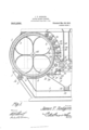
- Figure 1 is a vertical section through one half of a double gin embodying the present improvements.
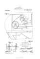
- Fig. 2 is a side elevation of that portion of the gin shown in Fig. 1.
- Fig. 3 is a detail view of the breast board adjusting mechanism.
- Fig. 4 is an elevation of a portion of the conveying cylinder and showing the arrangement of teeth thereon.
- characters of reference 1 designates a suitably constructed casing closed at one end by a hinged segmental hood 2 designed to normally rest 1n Specification of Letters Patent.
- This cylinder 3 is disposed above a smooth concave 6 secured within the casing 1 and spaced a desired distance from the teeth 5, there being a suction flue 7 extending from the concave 61 and throughout the length thereof, said fine being disposed 4adjacent the hood end of said concave and having a depression 8 in its inlet end 9 and in which is located a revoluble brush 10 so disposed as to remove from the teeth 5 any iibers adhering thereto.
- a hopper 11 is arranged at the inner side of the concave 6 and extends therebelow and opens into a trough 12, in which is arranged a worm-conveyer 13 designed to discharge the contents of the hopper from the machine.
- a feeding chamber 14C is arranged above the hopper 11 and may, if desired, be supplied with an ordinary gin feeder (not shown).
- a spreader 15 preferably in the form of an inverted V, may be located directly below the feeding chamber 14, this spreading device being used only in a double machine such as shown in Fig. 1, and wherein two conveying cylinders 3 are utilized, the hopper 11 being disposed between the two concaves 6. Inasmuch as both sides of the machine are similar in construction, only a little more than one half of the machine has been disclosed in Fig. 1.
- a screen 16 extends from the spreading device 15 and to the upper edge of a breast-board 17 which is hingedly mounted within the casing 1 and has ngers 18 outstanding therefrom and disposed close to a smooth roller 19 mounted to rotate within the casing.
- This roller and the breast-board are located in the upper l portion of the hopper 11, and interposed between roller 19 and the adjoining wall of the hopper is a hulling roller 20, having curved teeth 21 extending therefrom, said teeth being extended in a direction opposite to the direction of rotation of the cylinder.
- Any suitable means may be provided for securing the breast-board in adjusted position.
- said board has been shown connected by means of a link 22 with the lower portion of a pivoted hanger 23 engaged by a threaded stern 24.
- This stem is mounted to slide within an arcuate slot 25, formed within the casing 1, and has a hand-wheel 26 whereby it may be conveniently rotated for the purpose of drawing the hanger 23 tightly against the casing 1 to hold it and the breast-board against movement.
- two of these hangers may be utilized, one being disposed adjacent each side of the casing and both being connected to the breast-board by means of a link.
- the stem 2e may be provided with right and left hand threads for engaging the respective hangers so as to shift them against the adjoining walls of the casing when the wheel 26 is rotated.
- a iiighted cylinder 27 is arranged above the screen 16 and close to the spreader 15, there being a trough 28 above this cylinder' and coperating with the spreader 15 to form an outlet through which the material to be cleaned is discharged against the cylinder 27.
- a gin grate 29 extends from the trough 23 upwardly toward the cylinder 3, and a gang of gin saws 30 is arranged under and projects between the bars of this grate, said saws being located close to and above the flighted cylinder 27.
- a hulling roller 31 is located between cylinders 27 and 3, and below the saws 30, said roller being similar in construction to the roller 20 heretofore referred to.
- a worm conveyer 32 is located within the trough 2S and is designed to direct material from said trough to any suitable point of discharge, it being preferred to direct this material from one end of the trough and into the hopper 11.
- arcuate ribs or brackets 33 Secured upon the inner faces of the opposite walls of the casing and between the cylinder 3 and the feed chamber Hare arcuate ribs or brackets 33, each of which has blocks 34; adjustably connected to it by means of screws 35.
- These blocks are designed to support curved deflecting plates 36 extending close to the cylinder 3, and above which is arranged a hulling roller 3T, similar to the rollers 20 and 31 heretofore referred to.
- Another one of these hulling rollers is disclosed at 38 between the grate 29 and the lower deliecting plate 36. This roller is located at a greater distance from the teeth 5 than are the other rollers, the distances between the cylinder 3 and the rollers diminishing toward the upper end of the series of hulling rollers.
- the teeth of these rollers are designed to knock hulls and other foreign substances from the cylinder 3, and the teeth of the uppermost hulling rollers are arranged to work between the series of teeth on the cylinder' 3.
- the shafts of the hulling rollers 37 and 38 and the gin saws 30 are provided with pulleys 39, on which is mounted a belt 40, receiving motion from a pulley 41 mounted on the shaft 42 of cylinder 3.
- ldlers t3 are located at suitable points adjacent the pulleys 39 for the purpose of holding the belt in proper engagement with the pulleys 39.
- the shafts of the other parts of the mechanism may be actuated in any preferred manner, as by a belt located at the other side of the machine, and which has not been shown. All of the parts are designed to be rotated in the directions indicated by the arrows in Fig. 1.
- the grabot is supplied to the feed chamber 1li and is directed -by the deflector 15 against the tlighted cylinderl 27.
- This cylinder throws the material. against the hulling roller and against the teeth 5 on the cylinder 3, any dust or other fine foreign matter commingled with the product being discharged through the screen 16 and into the hopper 11. A certain portion vof the material will also be discharged past the breastboard 17 and into said hopper.
- the cylinder 3 rotates in the direction of the arrows shown in F ig. 1 the product adhering to the teeth 5 is conveyed upwardly past the roller 31, which serves to tear any large bolls or the like adhering to the cylinder, and as this material.
- the machine herein described can be provided with two sets of apparatus such as herein described, and, as a matter of fact, the mechanism illustrated in the accompanying drawings constitutes one half of a machine of this type. If preferred however, the machine can be constructed with but a single cylinder 3- and the necessary hulling rollers and other' portions of the mechanism cooperating therewith.
- fliglited cylinder may be used in lieu thereof, the same being designed to blow the fibers from the teeth and into the flue 7.
- lhat is claimed is l.
- a conveying cylinder having teeth thereon, gin saws adjacent thereto, a grate extending over the saws, a series of superposed deflecting plates above the grate and extending close to the cylinder, and hulling rollers arranged adjacent the cylinder, one roller being disposed above each plate.
- a cotton gin including a revoluble toothed cylinder', a feeding member, a screen for receiving material from the feeding member, a grate above the screen, gin saws adjacent the grate, means between the saws and screen for forcibly directing material from the feeding member and against the cylinder, hulling rolls for removing hulls from the cylinder at points above the grate, and means for directing the removed material from said rolls and downwardly on to the grate.
- a cotton gin comprising a toothed cylinder mounted for rotation, a concave therebelow and having a suction outlet, a hopper, a feed member disposed above the hopper, a screen interposed between the hopper and feed member, means above the screen for forcibly directing material from the feed member and against the cylinder, a breastboard suspended below one end of the screen and within the hopper, fingers outstanding therefrom, means for adjusting the breastboard, a smooth-faced roller in the path of the fingers, and a hulling-roll interposed between said roller and one wall of the hopper.
- a cotton gin a revoluble toothed cylinder, a grate adjacent thereto, gin saws below and extending between the bars of the grate, means for forcibly directing material against the cylinder, a screen below said means, a breast-board hingedly connected to the screen and extending therebelow, fingers extending from the board, a smoothfaced roller in the path of the lingers, means for adjusting the board, means for locking the board in adjusted position, and means for stripping hulls from the cylinder and means for directing the stripped hulls on to the grate.
Landscapes
- Engineering & Computer Science (AREA)
- Textile Engineering (AREA)
- Adjustment And Processing Of Grains (AREA)
Description
J. T. RODGBRS.
COTTON GRABOT CLEANER.
APPLICATION FILED FEB. s,
Patented Max'. 29, 1910.
2 SHEETS-SHEET 1` .Q ANnREw s. GRAHAM ce4 Puoovuwccmwmns, wAsmNGToN, o
J. 'I'. RODGERS. GOTTON GEABOT CLEANER.
APPLIGATIQN FILED PEB. a, 1909.
953,296. Patented Mar. 29, .1910.
2 SHEETS-SHEET Z.
NT FTQE.
JAMES TEAL RODGERS, OF NATCHEZ, MISSISSIPPI, ASSIGNOR OF ONE-FOURTH T0 HENRY C. TURLEY, OF NATCI-IEZ, MISSISSIPPI.
COTTON-GRABOT CLEANER.
Application tiled February 3, 1909.
To all lwho/m it may concern:
Be it known that I, Jnuns TEAL RoDGnRs, a citizen of the United States, residing at Natchez, in the county of Adams and State of Mississippi, have invented a new and useful Cotton-Grabot Cleaner, of which the following is a specification.
This invention relates to cotton gins and its object is to provide a machine of this character for cleaning the heretofore waste product, known generally as grabot, and which consists of a mixture of cotton ber, hulls and other foreign substances, separated from the cotton seed during their treatment in oil mills. Heretofore this product has usually been burned.
The object of the present invention however is to save the cotton fiber contained within this product.
Another object is to provide a gin of this character which is compact in construction and which includes mechanism whereby foreign substances of different sizes may be removed successively, the larger particles being first separated, and the smaller ones subsequently removed.
A further object is to provide means whereby the separated substances may be directed into a conveyer, means being utilized for removing from these separated portions any cotton which may cling thereto and for returning said cotton to the separating mechanism.
With these and other objects in view the invention consists of certain novel details of construction and combinations of parts hereinafter more fully described and pointed out in the claims.
In the accompanying drawings the preferred form of the invention has been shown.
In said drawings Figure 1 is a vertical section through one half of a double gin embodying the present improvements. Fig. 2 is a side elevation of that portion of the gin shown in Fig. 1.- Fig. 3 is a detail view of the breast board adjusting mechanism. Fig. 4: is an elevation of a portion of the conveying cylinder and showing the arrangement of teeth thereon.
Referring to the figures by characters of reference 1 designates a suitably constructed casing closed at one end by a hinged segmental hood 2 designed to normally rest 1n Specification of Letters Patent.
Patented Mar. 29, 1910.
Serial No. 475,823.
closed position and concentric with a conveying cylinder 3 journaled within the casing, said cylinder having lagging 4 upon the face or peripheral portion thereof, and from which extend spaced annular series of teeth 5 inclined in the direction of rotation of the cylinder and pointed, as clearly indicated in the drawings. This cylinder 3 is disposed above a smooth concave 6 secured within the casing 1 and spaced a desired distance from the teeth 5, there being a suction flue 7 extending from the concave 61 and throughout the length thereof, said fine being disposed 4adjacent the hood end of said concave and having a depression 8 in its inlet end 9 and in which is located a revoluble brush 10 so disposed as to remove from the teeth 5 any iibers adhering thereto.
A hopper 11 is arranged at the inner side of the concave 6 and extends therebelow and opens into a trough 12, in which is arranged a worm-conveyer 13 designed to discharge the contents of the hopper from the machine.
A feeding chamber 14C is arranged above the hopper 11 and may, if desired, be supplied with an ordinary gin feeder (not shown). A spreader 15 preferably in the form of an inverted V, may be located directly below the feeding chamber 14, this spreading device being used only in a double machine such as shown in Fig. 1, and wherein two conveying cylinders 3 are utilized, the hopper 11 being disposed between the two concaves 6. Inasmuch as both sides of the machine are similar in construction, only a little more than one half of the machine has been disclosed in Fig. 1. A screen 16 extends from the spreading device 15 and to the upper edge of a breast-board 17 which is hingedly mounted within the casing 1 and has ngers 18 outstanding therefrom and disposed close to a smooth roller 19 mounted to rotate within the casing. This roller and the breast-board are located in the upper l portion of the hopper 11, and interposed between roller 19 and the adjoining wall of the hopper is a hulling roller 20, having curved teeth 21 extending therefrom, said teeth being extended in a direction opposite to the direction of rotation of the cylinder. Any suitable means may be provided for securing the breast-board in adjusted position. In the drawings said board has been shown connected by means of a link 22 with the lower portion of a pivoted hanger 23 engaged by a threaded stern 24. This stem is mounted to slide within an arcuate slot 25, formed within the casing 1, and has a hand-wheel 26 whereby it may be conveniently rotated for the purpose of drawing the hanger 23 tightly against the casing 1 to hold it and the breast-board against movement. lf desired, two of these hangers may be utilized, one being disposed adjacent each side of the casing and both being connected to the breast-board by means of a link. The stem 2e may be provided with right and left hand threads for engaging the respective hangers so as to shift them against the adjoining walls of the casing when the wheel 26 is rotated.
A iiighted cylinder 27 is arranged above the screen 16 and close to the spreader 15, there being a trough 28 above this cylinder' and coperating with the spreader 15 to form an outlet through which the material to be cleaned is discharged against the cylinder 27. A gin grate 29 extends from the trough 23 upwardly toward the cylinder 3, and a gang of gin saws 30 is arranged under and projects between the bars of this grate, said saws being located close to and above the flighted cylinder 27. A hulling roller 31 is located between cylinders 27 and 3, and below the saws 30, said roller being similar in construction to the roller 20 heretofore referred to. A worm conveyer 32 is located within the trough 2S and is designed to direct material from said trough to any suitable point of discharge, it being preferred to direct this material from one end of the trough and into the hopper 11.
Secured upon the inner faces of the opposite walls of the casing and between the cylinder 3 and the feed chamber Hare arcuate ribs or brackets 33, each of which has blocks 34; adjustably connected to it by means of screws 35. These blocks are designed to support curved deflecting plates 36 extending close to the cylinder 3, and above which is arranged a hulling roller 3T, similar to the rollers 20 and 31 heretofore referred to. Another one of these hulling rollers is disclosed at 38 between the grate 29 and the lower deliecting plate 36. This roller is located at a greater distance from the teeth 5 than are the other rollers, the distances between the cylinder 3 and the rollers diminishing toward the upper end of the series of hulling rollers. The teeth of these rollers are designed to knock hulls and other foreign substances from the cylinder 3, and the teeth of the uppermost hulling rollers are arranged to work between the series of teeth on the cylinder' 3. By referring to Fig; 2 it will be noted that the shafts of the hulling rollers 37 and 38 and the gin saws 30 are provided with pulleys 39, on which is mounted a belt 40, receiving motion from a pulley 41 mounted on the shaft 42 of cylinder 3. ldlers t3 are located at suitable points adjacent the pulleys 39 for the purpose of holding the belt in proper engagement with the pulleys 39. The shafts of the other parts of the mechanism may be actuated in any preferred manner, as by a belt located at the other side of the machine, and which has not been shown. All of the parts are designed to be rotated in the directions indicated by the arrows in Fig. 1.
in using the machine herein described the grabot is supplied to the feed chamber 1li and is directed -by the deflector 15 against the tlighted cylinderl 27. This cylinder throws the material. against the hulling roller and against the teeth 5 on the cylinder 3, any dust or other fine foreign matter commingled with the product being discharged through the screen 16 and into the hopper 11. A certain portion vof the material will also be discharged past the breastboard 17 and into said hopper. As the cylinder 3 rotates in the direction of the arrows shown in F ig. 1 the product adhering to the teeth 5 is conveyed upwardly past the roller 31, which serves to tear any large bolls or the like adhering to the cylinder, and as this material. is conveyed upwardly by the cylinder 3 the rollers 3S and 37 successively act upon it to throw therefrom any hulls or other objectionable substances adhering thereto. These hulls and the like will be discharged on to the plates 36 and directed thereby on to the grate 29, where the gin saws 30 will remove any cotton fiber which may cling to the hulls discharged on to the grate. This ber will be drawn into the space above the screen 16 and again directed against the cylinder 3 by the flighted cylinder 27. The waste material discharged from the grate 29 will fall into the trough 23 and be carried away from the machine by the conveyer 32. The cleaned cotton remaining upon the cylinder 3 travels around the cylinder and under the hood 2 until it reaches the brush 10. This brush rotates at a much greater speed than the cylinder 3 and will operate to remove the bers from the teeth 5 and direct them into the suction flue 7. The cotton is designed to be vconveyed through this flue to the gin.
As heretofore stated the machine herein described can be provided with two sets of apparatus such as herein described, and, as a matter of fact, the mechanism illustrated in the accompanying drawings constitutes one half of a machine of this type. If preferred however, the machine can be constructed with but a single cylinder 3- and the necessary hulling rollers and other' portions of the mechanism cooperating therewith.
Although a brush 10 has been described and shown in connection with cylinder 3, it is to be understood that, if preferred, a
fliglited cylinder may be used in lieu thereof, the same being designed to blow the fibers from the teeth and into the flue 7.
Obviously various changes may be made in the construction and arrangement of the parts without departing from the spirit or sacrificing the advantages of the invention.
lhat is claimed is l. In a gin a conveying cylinder having teeth thereon, gin saws adjacent thereto, a grate extending over the saws, a series of superposed deflecting plates above the grate and extending close to the cylinder, and hulling rollers arranged adjacent the cylinder, one roller being disposed above each plate.
2. The combination with a revoluble toothed cylinder, of a grate, gin saws adjacent the grate, a series of hulling rolls above the grate and adajcent the cylinder, and curved deflecting plates adjustably mounted adjacent, and projecting between the hulling rolls for=I directing material from said rolls to the grate.
3. A cotton gin including a revoluble toothed cylinder', a feeding member, a screen for receiving material from the feeding member, a grate above the screen, gin saws adjacent the grate, means between the saws and screen for forcibly directing material from the feeding member and against the cylinder, hulling rolls for removing hulls from the cylinder at points above the grate, and means for directing the removed material from said rolls and downwardly on to the grate.
4. The combination with a casing and a hood closing one end thereof, of a toothed cylinder mounted for rotation within the casing, a concave below the cylinder and within the casing, an outlet Hue extending from the concave, means within the flue for brushing the material from the teeth on the cylinder, a feeding member, means for directing material forcibly from said member and against the toothed cylinder, superposed hulling rolls adjacent the lcylinder, a trough, and means for directing hulls from the rolls to the trough.
5. A cotton gin comprising a toothed cylinder mounted for rotation, a concave therebelow and having a suction outlet, a hopper, a feed member disposed above the hopper, a screen interposed between the hopper and feed member, means above the screen for forcibly directing material from the feed member and against the cylinder, a breastboard suspended below one end of the screen and within the hopper, fingers outstanding therefrom, means for adjusting the breastboard, a smooth-faced roller in the path of the fingers, and a hulling-roll interposed between said roller and one wall of the hopper.
6. In a cotton gin a revoluble toothed cylinder, a grate adjacent thereto, gin saws below and extending between the bars of the grate, means for forcibly directing material against the cylinder, a screen below said means, a breast-board hingedly connected to the screen and extending therebelow, fingers extending from the board, a smoothfaced roller in the path of the lingers, means for adjusting the board, means for locking the board in adjusted position, and means for stripping hulls from the cylinder and means for directing the stripped hulls on to the grate.
In testimony that I claim the foregoing as my own, I have hereto aflixed my signature in the presence of two witnesses.
JAMES TEAL RODGERS.
Witnesses:
H. C. TURLEY, RoB'r. F. DALE.
Priority Applications (1)
| Application Number | Priority Date | Filing Date | Title |
|---|---|---|---|
| US47582309A US953296A (en) | 1909-02-03 | 1909-02-03 | Cotton-grabot cleaner. |
Applications Claiming Priority (1)
| Application Number | Priority Date | Filing Date | Title |
|---|---|---|---|
| US47582309A US953296A (en) | 1909-02-03 | 1909-02-03 | Cotton-grabot cleaner. |
Publications (1)
| Publication Number | Publication Date |
|---|---|
| US953296A true US953296A (en) | 1910-03-29 |
Family
ID=3021704
Family Applications (1)
| Application Number | Title | Priority Date | Filing Date |
|---|---|---|---|
| US47582309A Expired - Lifetime US953296A (en) | 1909-02-03 | 1909-02-03 | Cotton-grabot cleaner. |
Country Status (1)
| Country | Link |
|---|---|
| US (1) | US953296A (en) |
-
1909
- 1909-02-03 US US47582309A patent/US953296A/en not_active Expired - Lifetime
Similar Documents
| Publication | Publication Date | Title |
|---|---|---|
| US1222523A (en) | Cotton-gin feeder. | |
| US1280863A (en) | Pneumatic cotton-gin. | |
| US537764A (en) | Machine for cleaning and separating baled hay | |
| US1721932A (en) | Cotton-cleaning assembly | |
| US1180134A (en) | Cotton cleaning and renovating plant. | |
| US830646A (en) | Cotton elevator, cleaner, and feeder. | |
| US391744A (en) | Seed-cotton cleaner | |
| US654079A (en) | Seed-cotton cleaner and feeder. | |
| US3231939A (en) | Apparatus for ginning cotton | |
| USRE16513E (en) | Assigkktok to eardwicke-ettek | |
| US1514044A (en) | Cotton-cleaning machine | |
| US1304804A (en) | Boll-cotton sepabatob and cleaneb | |
| US434859A (en) | beott | |
| US1216673A (en) | Separator for seed-cotton. | |
| US1630638A (en) | Hull and cotton separator and cleaner | |
| US962343A (en) | Cotton huller and cleaner. | |
| US1526392A (en) | Cleaner feeder for cotton gins | |
| US765874A (en) | Cotton thresher and cleaner. | |
| US1287222A (en) | Apparatus for separating and cleaning hulls and trash from seed-cotton. | |
| US1075304A (en) | Pneumatic cleaning device. | |
| US1510069A (en) | Cotton-hull-extracting machine | |
| US269387A (en) | Seed-cotton separator and cleaner | |
| US496367A (en) | Cotton feeder and cleaner | |
| US868944A (en) | Fiber-cleaning machine. | |
| US944507A (en) | Fiber-cleaning machine. |