US830646A - Cotton elevator, cleaner, and feeder. - Google Patents
Cotton elevator, cleaner, and feeder. Download PDFInfo
- Publication number
- US830646A US830646A US29195005A US1905291950A US830646A US 830646 A US830646 A US 830646A US 29195005 A US29195005 A US 29195005A US 1905291950 A US1905291950 A US 1905291950A US 830646 A US830646 A US 830646A
- Authority
- US
- United States
- Prior art keywords
- cotton
- cleaner
- pipe
- cleaners
- valve
- Prior art date
- Legal status (The legal status is an assumption and is not a legal conclusion. Google has not performed a legal analysis and makes no representation as to the accuracy of the status listed.)
- Expired - Lifetime
Links
- 229920000742 Cotton Polymers 0.000 title description 75
- 241000254175 Anthonomus grandis Species 0.000 description 6
- 238000010276 construction Methods 0.000 description 4
- 230000007246 mechanism Effects 0.000 description 4
- 239000010813 municipal solid waste Substances 0.000 description 3
- 241000238631 Hexapoda Species 0.000 description 2
- 238000004140 cleaning Methods 0.000 description 2
- 230000003028 elevating effect Effects 0.000 description 2
- 238000005192 partition Methods 0.000 description 2
- 230000001105 regulatory effect Effects 0.000 description 2
- NFLLKCVHYJRNRH-UHFFFAOYSA-N 8-chloro-1,3-dimethyl-7H-purine-2,6-dione 2-(diphenylmethyl)oxy-N,N-dimethylethanamine Chemical compound O=C1N(C)C(=O)N(C)C2=C1NC(Cl)=N2.C=1C=CC=CC=1C(OCCN(C)C)C1=CC=CC=C1 NFLLKCVHYJRNRH-UHFFFAOYSA-N 0.000 description 1
- 238000007664 blowing Methods 0.000 description 1
- 230000001276 controlling effect Effects 0.000 description 1
- 230000003247 decreasing effect Effects 0.000 description 1
- 239000000428 dust Substances 0.000 description 1
- 239000012535 impurity Substances 0.000 description 1
- 239000002184 metal Substances 0.000 description 1
- 238000000034 method Methods 0.000 description 1
- 230000002093 peripheral effect Effects 0.000 description 1
- 238000000926 separation method Methods 0.000 description 1
- 239000010409 thin film Substances 0.000 description 1
Images


Classifications
-
- D—TEXTILES; PAPER
- D01—NATURAL OR MAN-MADE THREADS OR FIBRES; SPINNING
- D01G—PRELIMINARY TREATMENT OF FIBRES, e.g. FOR SPINNING
- D01G9/00—Opening or cleaning fibres, e.g. scutching cotton
Definitions
- My invention relates to certain new and useful improvements in cotton elevators, cleaners, and feeders.
- the object of my invention to provide means for handling cotton which will be automaticdn their action and which will more thoroughly cleanthe cotton than has hereto- 7 gforebeen possible and which at the same time Wlll remove and killany boll-weevils or other insects which may be in the cotton.
- My invention is particularly designed for the purpose of elevating, conveying, and
- One object of my invention is to combine with the elevating and conveying mechanism for the cotton positive means for separating and removing boll-weevils, dust, leaf trash, and other impurities before the cotton is passed to the gins, the boll-weevils after they are separated from the cotton being killed as they pass through the machine.
- I further provide means by which the" amount of cotton fed to the cleaners is automatically regulated by the supply of cotton to not become clogged up the cleaners. Consequently the cleancrswill cotton and the cotton will not be fed so fast through the cleanersas to prevent the" thorough separation of all foreign matters from the cotton.
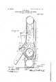
- Fig. 3 is a transverse section of the cleaner shown in Fig. 2, taken on line 3 3 of Fig. 2.
- Fig. 4 is asectionof the taken on line 4 4 of Fig. 3.
- 1 designates the pneumatic conveyer through which the cotton is carried by an air suctionthat is to say, means are provided for producing-a suction in the pipe which by withdrawing or exhausting the air from sald conveyer and admitting air from the part of the conveyer where the cotton is introduced will cause the cotton to be car-f ried along by the current of air so produced.
- the open end of the conveyer is provided with a drop-pipe 2 of any desired form,by which cotton may be picked up from a wagonthe cotton in the wellknown manner.
- ' 3 designates a series of cleaner-boxes, which are connected at their upper ends to the conveyer 1, as is shown in Fig. 4.
- each' cleaner is provided with .a foraminous partition 4 of Wire screen or the like which divides the cleaner into two chambers 5 and 6.
- the foraminous wall 4 is connected at its upper end to the topof its lower and to across-piece .7. 8 is a shield 'of sheet-metal or the like extending down from the cross-piece? and connected at its lower ondto the top of a pipe 9, which extends below all the cleaners and to one end of which there is connected an exhaust-fan 10.
- 11' is an opening provided in the top of the pipe 9 adjacent to the end of each of the shields8, these openings being each provided with 'a valve 12, bywhich the width of each opening'may be varied.
- -13. is a pipe leading from the opening in the side of the pipe 9 behind each of the shields 8 and into the chambers 6.
- the feed-rollers 14 Located in the sides of the cleaner, preferably just below the strip 7, are the feed-rollers 14 15, these rollers being provided with spikes 16 and adapted to be driven in the directions of the arrows'(s hown inFig. 4) by means tobe hereinafter des, 17 is a cylinder or drum mounted the chamber. 5 and at in'the lower portion of the cleaner belowthe rollers 14 and 15 and provided with r'ojections 18.
- 19 a foraminous screen w iich at one end is connected to the partition 8 and at the other end to a cross-stri 20, the screen being curved, as shown in ig.
- the drums 17 are mounted on a shaft 26, which extends through the battery of cleaners and is provided on one end with a driving-pulley which power is supplied.
- each of the'cleaners Just outside the casirw I provide a disk gear 28, which is fast on t e shaft 26, and 29 is a disk mounted in a plane at right angles to disk gear 28 and supported on sleeve 30, feathered on a shaft 31,-mounted in a suitable bracket 32, so that an edge of the disk 29 will be in contact with the face of the disk 28.
- rotation of the shaft may be varied by moving the'disk 29 toward or awa from the periphery of'the disk 28;
- the s aft 31 is provided on its upper end with a worm 33,which which meshes with a gear 37, mounted on the shaft 38 of the feed-roller 14, whereby the rollers will be driven at the same speed and in the direction of the arrows, (shown in Fig. 4,)
- the shaft of the feed-roller 23 is preferably mounted in boxes 43', which are mounted in slots, and the boxes are held in the slots by the sprin s, 44, whereby the feed roller 23 1s yielding y pressed toward the feed-roller 24.
- the cleaners are all alike, and the description of one appliesto all.
- the fan 10 is 50 placed at the end of the pipe 9 ofthe battery of cleaners opposite that at which the'conveyer 1 takes in the cotton. Adjacent to the fan the pipe9 is provided with a valve 45, which when open will admit air directly to the fan, and consequently check the suction By mounting the disk' 29 on a' sleeve feathered to the shaft31 the speed of on the system, but the free admission of air to the fan will permit it to be used for blowing although the cleaner may be out of action. When the cotton has been cleaned, it is passed to the gins and separated from the seed.
- the seed is then conveyed by a screw or other conveyer to the exhaust-pipe of the fan 10 and by that exhaust-blast driven to the cotton-seed house,
- the exhaust-blast was stopped by the choking of the cleaner or shutting it down; but in my device I stop the operation of the cleaner by opening the valve 45, which cuts off the suction from the cleaner, but leaves the fan in full operation to remove the seed as fast as it comes from thegins.
- Theflow of seed from the gins is constant so longi'as they are supplied with cotton, and if the fan is-relied upon to carry away this seed it must'be in constant operation or the machine will become clogged with the seed and cannot then be started without cleaning out and great delay. Hence it is of the highest importance that'the fan should never be stopped or reduced materially in power while seed is coming from thegins.
- the 46 is aplate pivotally mounted in the chamber 5 of the cleaner which is adjacent to the fan".
- This plate 46 is provided with an arm 47, which extends outside the cleaner and is connected by a link 48 to the valve 45.
- the valve 45 is formed by a series of slots in the pipe 9 and a series of slots in the plate which forms the other member of the valve. These slots are so located that when the plate 46 is in position as shown in dotted lines in Fig. 4 the slots will register and the valve will-be open. When, however, the plate 46 is in the position shown in full lines in Figf4 the valve will be closed, as shown in Fig. 2.
- valve-actuating mechanism is so balanced that when a sufficient suppl of cotton is in the upper part of the chamber 10 to move the plate 46 from the full line position (shown in Fig. 4) to the dottedline position the valve 45 will be opened, and consequently the suction of the fan on the sys-- tern will be stopped, thus stopping the feed of cotton.
- the cotton at the lower end of the chamber 5 is passed between the feedrolls 14 and 15 as they turn, butsaid feedrolls turn slowly, and as the cotton is slowly passed down by the feed-rolls it is caught by theteeth of the roller 17 which is travelin at a much higher speed, in small portions and carried to .the screen 19.
- the feed-rolls 14 and 15 turn ata speed of two to three revolutions per minute, while the roller 17 turns at a speed of one hundred and-seventy revolutions per minute, with the result that the peripheral speed of roller 17 is about two hundred times as great as that of the feed-rolls.
- each of the cleaners With a valve 50, pivoted inthe side of each of the cleaners. These valves are preferabl mounted on a shaft 51, extending throng the whole battery of cleaners and provided at a suitable point with an operating-handle 52.
- valve may be shut and'the pipe 2 fed with a iresh supply of cotton, which will be drawn into the (learn-rs above the valve.
- the valve can now be left closed until'all the cotton below the valve has passed out and into the gins, when upon opening the ,valve the fresh cotton is allowedto pass through
Landscapes
- Engineering & Computer Science (AREA)
- Textile Engineering (AREA)
- Preliminary Treatment Of Fibers (AREA)
Description
No. 830,646. PATENTED SEPT.,11, 1906.
v s. M. DAVIS.
GOTTON ELEVATOR, CLEANER, AND FEEDER.
APILIIOATION FILED DEG. 16.1905.
3 sums-sum 1.
s. M. DAVIS.
PATENTED SEPT. 11, 1906.
COTTON ELEVATOR, CLEANER, AND FEEDER.
APPLICATION IILBD DEO.15,1905.
r I I h 3 SHEETS-SHEET 2.
l I l 'auuenfoz N0. 830,646. PATEN TEE SEPT. 11, 1906.
- s. M. DAVIS. I
' GOTTON ELEVATOR, CLEANER, AND FEEDER.
APPLICATION FILED DEC. 15.1905.
3 SHEETS-SHEBT 3.
QMDaViS UNITED STATES PATENT OFFICE.
SAMUEL M. Davis, on BALTIMORE, MARYLAND. COTTON ELEVATOR, CLEANER, AND FEEDER- No. 83o,646.
' have invented certain new and useful Improvernents in Cotton Elevators ,Cleaners, and eeders, of which the following is a specificatlon.
My invention relates to certain new and useful improvements in cotton elevators, cleaners, and feeders.
- fThe object of my invention to provide means for handling cotton which will be automaticdn their action and which will more thoroughly cleanthe cotton than has hereto- 7 gforebeen possible and which at the same time Wlll remove and killany boll-weevils or other insects which may be in the cotton.
My invention is particularly designed for the purpose of elevating, conveying, and
-' cleaning the cotton and feeding it directly to the gins, whereby the cotton is lmproved in quality and the method of handling rendered more simple and economical than heretofore, the supply of cotton to the cleaners being automatically regulated by the cotton itself,
- the killing of the boll-weevils and other insects being incident to these operations.
One object of my invention -is to combine with the elevating and conveying mechanism for the cotton positive means for separating and removing boll-weevils, dust, leaf trash, and other impurities before the cotton is passed to the gins, the boll-weevils after they are separated from the cotton being killed as they pass through the machine. By
my construction all foreign matter is removed from the cotton before 1t passes to the gins. Gonseq'uently the saws are not liable to be clo ed or broken orrapidlyworn away, as will be the case when all foreign matter is not' separated from the cotton before passing to the gins.
I further provide means by which the" amount of cotton fed to the cleaners is automatically regulated by the supply of cotton to not become clogged up the cleaners. Consequently the cleancrswill cotton and the cotton will not be fed so fast through the cleanersas to prevent the" thorough separation of all foreign matters from the cotton.
For the purpose of disclosingthe referred form of my invention, so as to ena le those skilled in the art to make and use the same, reference is had to the accompanying draw- Specification of Letters Patent. Application filed December 1.5,1905. Seria11o.291,950.
.or other container of by an oversupply of scribed.
Patented Sept. 11, 1906.
ings and specification, wherein the same parts are designated by the same referenceright of Fig. 1, showing the means for'automatically controlling the supply of cotton to the cleaners. Fig. 3 is a transverse section of the cleaner shown in Fig. 2, taken on line 3 3 of Fig. 2. Fig. 4 is asectionof the taken on line 4 4 of Fig. 3.
1 designates the pneumatic conveyer through which the cotton is carried by an air suctionthat is to say, means are provided for producing-a suction in the pipe which by withdrawing or exhausting the air from sald conveyer and admitting air from the part of the conveyer where the cotton is introduced will cause the cotton to be car-f ried along by the current of air so produced. The open end of the conveyer is provided with a drop-pipe 2 of any desired form,by which cotton may be picked up from a wagonthe cotton in the wellknown manner. I
' 3 designates a series of cleaner-boxes, which are connected at their upper ends to the conveyer 1, as is shown in Fig. 4. Re-
cleaner,
ferring to Fig.4, it will be seen that each' cleaner is provided with .a foraminous partition 4 of Wire screen or the like which divides the cleaner into two chambers 5 and 6. The foraminous wall 4 is connected at its upper end to the topof its lower and to across-piece .7. 8 is a shield 'of sheet-metal or the like extending down from the cross-piece? and connected at its lower ondto the top of a pipe 9, which extends below all the cleaners and to one end of which there is connected an exhaust-fan 10. 11' is an opening provided in the top of the pipe 9 adjacent to the end of each of the shields8, these openings being each provided with 'a valve 12, bywhich the width of each opening'may be varied. -13.is a pipe leading from the opening in the side of the pipe 9 behind each of the shields 8 and into the chambers 6. Located in the sides of the cleaner, preferably just below the strip 7, are the feed-rollers 14 15, these rollers being provided with spikes 16 and adapted to be driven in the directions of the arrows'(s hown inFig. 4) by means tobe hereinafter des, 17 is a cylinder or drum mounted the chamber. 5 and at in'the lower portion of the cleaner belowthe rollers 14 and 15 and provided with r'ojections 18. 19 a foraminous screen w iich at one end is connected to the partition 8 and at the other end to a cross-stri 20, the screen being curved, as shown in ig. 4, so that it forms a ""gment of a circle around the drum 17, past which the cotton is carried. 21 is a curved deflector-plate held in position by supports 22 'andadapted to remove the cotton from the projections on the drum and deflect it between the pair of feedrollers 23 and 24 and into the chute 25, by which the cotton passes into the gin. The drums 17 are mounted on a shaft 26, which extends through the battery of cleaners and is provided on one end with a driving-pulley which power is supplied. At one side of each of the'cleaners Just outside the casirw I provide a disk gear 28, which is fast on t e shaft 26, and 29 is a disk mounted in a plane at right angles to disk gear 28 and supported on sleeve 30, feathered on a shaft 31,-mounted in a suitable bracket 32, so that an edge of the disk 29 will be in contact with the face of the disk 28.
rotation of the shaft may be varied by moving the'disk 29 toward or awa from the periphery of'the disk 28; The s aft 31 is provided on its upper end with a worm 33,which which meshes with a gear 37, mounted on the shaft 38 of the feed-roller 14, whereby the rollers will be driven at the same speed and in the direction of the arrows, (shown in Fig. 4,)
" the speed of these rollers being varied as desired by the adjustment pf the sleeve 30 on the shaft 31. Mounted on the shaft 26 adjacent ,to each of the cleaners is a sprocket-- wheel 39, over whichruns a sprocket- chain 40, and 41 is an idle sprocket-wheel, over which the other end of the chain runs. 42 is a sprocket-wheel mounted on one end of the shaft of the feed-rolle1= 24 and engaging the side of the sprocket-chain 40, by which-it is driven. The shaft of the feed-roller 23 is preferably mounted in boxes 43', which are mounted in slots, and the boxes are held in the slots by the sprin s, 44, whereby the feed roller 23 1s yielding y pressed toward the feed-roller 24. As far as described the cleaners are all alike, and the description of one appliesto all.
Preferably and as shown. the fan 10 is 50 placed at the end of the pipe 9 ofthe battery of cleaners opposite that at which the'conveyer 1 takes in the cotton. Adjacent to the fan the pipe9 is provided with a valve 45, which when open will admit air directly to the fan, and consequently check the suction By mounting the disk' 29 on a' sleeve feathered to the shaft31 the speed of on the system, but the free admission of air to the fan will permit it to be used for blowing although the cleaner may be out of action. When the cotton has been cleaned, it is passed to the gins and separated from the seed. The seed is then conveyed by a screw or other conveyer to the exhaust-pipe of the fan 10 and by that exhaust-blast driven to the cotton-seed house, In cleaners heretofore in use the exhaust-blast was stopped by the choking of the cleaner or shutting it down; but in my device I stop the operation of the cleaner by opening the valve 45, which cuts off the suction from the cleaner, but leaves the fan in full operation to remove the seed as fast as it comes from thegins. Theflow of seed from the gins is constant so longi'as they are supplied with cotton, and if the fan is-relied upon to carry away this seed it must'be in constant operation or the machine will become clogged with the seed and cannot then be started without cleaning out and great delay. Hence it is of the highest importance that'the fan should never be stopped or reduced materially in power while seed is coming from thegins.
46" is aplate pivotally mounted in the chamber 5 of the cleaner which is adjacent to the fan". This plate 46 is provided with an arm 47, which extends outside the cleaner and is connected by a link 48 to the valve 45. As shown, the valve 45 is formed by a series of slots in the pipe 9 and a series of slots in the plate which forms the other member of the valve. These slots are so located that when the plate 46 is in position as shown in dotted lines in Fig. 4 the slots will register and the valve will-be open. When, however, the plate 46 is in the position shown in full lines in Figf4 the valve will be closed, as shown in Fig. 2. The valve-actuating mechanism is so balanced that when a sufficient suppl of cotton is in the upper part of the chamber 10 to move the plate 46 from the full line position (shown in Fig. 4) to the dottedline position the valve 45 will be opened, and consequently the suction of the fan on the sys-- tern will be stopped, thus stopping the feed of cotton. As soon as the amount of cotton in the chamber has been decreased by the feedrollers 14 and 15 so that the plate 46 can swing to its full-line position due to the weight of theparts overcoming the pressure of the cotton the valve ,will be closed, thus throwing the suction ontothe system, and consequently causing the cotton to again pass to the cleaners.= I have located this valve-controlling mechanism on the cleaner farthest from the receiving end ofthe conveyer, whereby the supply of cotton will not beout off until the entire battery of cleaners is sup-' plied with cotton.
In the operation of .my niachin'e'after it has been set in operation the pipe 2 is connectedto a suitable source of supply of cotton,
, when the suction produced by the fan '10 will draw the cotton through the. conveyer-pipe and into the chamberfiof the cleaners. T 1e cotton in the chamber 5 will pass down in front of the screen 4 ,andpart of thedirt and trash in the cotton will pass through the screen,
down the chamber 6, and through the pipe 13 into the pipe 9. The cotton at the lower end of the chamber 5 is passed between the feedrolls 14 and 15 as they turn, butsaid feedrolls turn slowly, and as the cotton is slowly passed down by the feed-rolls it is caught by theteeth of the roller 17 which is travelin at a much higher speed, in small portions and carried to .the screen 19. The feed-rolls 14 and 15 turn ata speed of two to three revolutions per minute, while the roller 17 turns at a speed of one hundred and-seventy revolutions per minute, with the result that the peripheral speed of roller 17 is about two hundred times as great as that of the feed-rolls.
. The cotton is thus carded out into a very thin film before it is passed over the screen 19,
where the remaining trash and foreign matter, including the boll-weevils which may be in the cotton, are all separated and pass through thescreen 19 into the pipe 9, the cotton being carried around by the drum 17until it reaehesthe deflector 21, where it is picked up and passed into the feed-roller 23 to the chute 25 into the gin. The fan 10 is run at a a very high rate of speed, and all matter dropping into the pipe 9 must pass through the fan 10. Consequently any boll-weevils which were in the cotton having been separated from the cottoniby the cleaner and drop ed into the pipe 9 will pass through the an.
They will be struckbvthe blades of the fan in passing through the fan and will be killed, thus preventing them from getting into the cotton-seed to do further damage.
By myautomatic regulator for the supply of cotton to the cleaners, which I have described, the cleaners are kept at their maximum ellicieney and clogging of the cleanersby feeding too much cotton into the cleaners is avoided.
In order to bejable to separate different lots of cotton, I provide each of the cleaners with a valve 50, pivoted inthe side of each of the cleaners. These valves are preferabl mounted on a shaft 51, extending throng the whole battery of cleaners and provided at a suitable point with an operating-handle 52.
By this construction after all the cotton in the cleaners has passed below the valves the valve may be shut and'the pipe 2 fed with a iresh supply of cotton, which will be drawn into the (learn-rs above the valve. The valve can now be left closed until'all the cotton below the valve has passed out and into the gins, when upon opening the ,valve the fresh cotton is allowedto pass through In conse:
quence of. this construction it will be possible to' k eep separate different lots of cotton without stopping the operation of the gins. I While I'have described what I believe tobe the preferred form of my invention, I de- 1 sire to have it understood that manychanges can be made in the form, construction, and
arrangement of parts and other mechanisms substituted for that shown and described for carrying out the operation described with- 1 o'ut departing from my invention- What I desire to claimas new and secure by Letters Patent is'- I 1. The combination with a series of cleaners for cotton, each adapted to supply cotton to a gin, of means for supplying cotton to all the cleaners, and means controlled by the amount of cotton in one of the cleaners to control the supply of cotton to all the clean ers. I
2. The eombinationwith a conveyer-pi e, of a series of cleaners to which cotton is ed from the conveyer pipe, an exhaust-pipe connected to the cleaners, means for producing an exhaust in the exhaust-pipe, and means controlled by the sup ly of cotton in one of the cleaners to control the exhaust.
3. I The combination'with a conveyer-pipe, of a cleaner to which cotton is fed from the conveyor-pipe, an exhaustipe connected to the cleaner, means for pro ucing an exhaust conveyer-pipe, an exhaust-pipe connected to i the cleaner, means for producing an exhaust 1n the pipe, a valve in the exhaustipe opening to the atmosphere, It pivoted p ate in the cleaner adapted to be operated by the cotton fed to the cleaner, and connections between the plate and the valve whereby the amount of cotton in the cleaner will control the oper- I ation of the valve.
5. The combination with a conveyer-pipe, of a cleaner to which cotton is fed from the conveyer-pipe, an exhaustipe connected to the cleaner, means for pro ucing an exhaust in the exhaust-pipe and a valve in the exhaust-pipe located betweenthe cleaner andthe exhausting device, said valve openin to the atmosphere, and means for controllin the opening and closing of the valve operate by the supply of cotton in the cleaner.
6 The combination with a conveyer-pi e, of a cleaner to which cotton is fed from t e conveyor-pipe, an exhaustipe connected to the cleaner, means for pro ucing an exhaust in the pipe, a valve in the exhaust-pipe located between the cleaner and the exhausting device, said valve opening to the atmosphere, a pivoted plate in the cleaner adapted to be operated by the cotton fedto thecleaner, and connections between the plate and the valve, whereby the amount of cotton in the cleaner will control the operation of 5 the valve. .1 7. A cleaner adapted to clean cotton comsed of a. chamber into which the cotton is ed, having a fomminous Side well, a pair of feed-rollers located in-the lower part of the I0 chamber; a drum located below the feed-roll- -e1's,- iiiorerm'nous well located below the drum past which the cotton is carried by the drum,
en imperforated Wall between the two foraminous walls, an exhaust-pipe below the lower foraminous wall and a connection between r 5 "Maryland, this 30th day of December, 1904.
SAMUEL M.- DAVIS Witnesses:
LESTER H. LATHAM, T. A. LEE.
Priority Applications (1)
| Application Number | Priority Date | Filing Date | Title |
|---|---|---|---|
| US29195005A US830646A (en) | 1905-12-15 | 1905-12-15 | Cotton elevator, cleaner, and feeder. |
Applications Claiming Priority (1)
| Application Number | Priority Date | Filing Date | Title |
|---|---|---|---|
| US29195005A US830646A (en) | 1905-12-15 | 1905-12-15 | Cotton elevator, cleaner, and feeder. |
Publications (1)
| Publication Number | Publication Date |
|---|---|
| US830646A true US830646A (en) | 1906-09-11 |
Family
ID=2899122
Family Applications (1)
| Application Number | Title | Priority Date | Filing Date |
|---|---|---|---|
| US29195005A Expired - Lifetime US830646A (en) | 1905-12-15 | 1905-12-15 | Cotton elevator, cleaner, and feeder. |
Country Status (1)
| Country | Link |
|---|---|
| US (1) | US830646A (en) |
Cited By (3)
| Publication number | Priority date | Publication date | Assignee | Title |
|---|---|---|---|---|
| US2609313A (en) * | 1947-07-26 | 1952-09-02 | Johns Manville | Method and apparatus for opening fibrous agglomerations |
| US2696025A (en) * | 1951-08-31 | 1954-12-07 | Lummus Cotton Gin Co | Means for controlling supply of seed cotton to precleaning and drying equipment |
| US3122792A (en) * | 1958-05-30 | 1964-03-03 | J W Roberts Ltd | Machines for spraying asbestos or the like |
-
1905
- 1905-12-15 US US29195005A patent/US830646A/en not_active Expired - Lifetime
Cited By (3)
| Publication number | Priority date | Publication date | Assignee | Title |
|---|---|---|---|---|
| US2609313A (en) * | 1947-07-26 | 1952-09-02 | Johns Manville | Method and apparatus for opening fibrous agglomerations |
| US2696025A (en) * | 1951-08-31 | 1954-12-07 | Lummus Cotton Gin Co | Means for controlling supply of seed cotton to precleaning and drying equipment |
| US3122792A (en) * | 1958-05-30 | 1964-03-03 | J W Roberts Ltd | Machines for spraying asbestos or the like |
Similar Documents
| Publication | Publication Date | Title |
|---|---|---|
| US830646A (en) | Cotton elevator, cleaner, and feeder. | |
| US418084A (en) | Cotton-elevator | |
| US3988806A (en) | Apparatus for cleaning seed cotton | |
| US604426A (en) | Cotton elevator | |
| US732869A (en) | Cotton huller, cleaner, and gin-feeder. | |
| US1721932A (en) | Cotton-cleaning assembly | |
| US1538244A (en) | Cotton cleaner | |
| US884671A (en) | Bur-cotton thresher, cleaner, and storage unloader. | |
| US1087882A (en) | Cotton elevating and distributing system. | |
| US391744A (en) | Seed-cotton cleaner | |
| US2081412A (en) | Combination huller and feeder | |
| US953296A (en) | Cotton-grabot cleaner. | |
| US755701A (en) | Cotton-separator. | |
| US1514044A (en) | Cotton-cleaning machine | |
| US844842A (en) | Combined feeding, cleaning, and elevating apparatus. | |
| US804888A (en) | Pneumatic gin-feeder. | |
| US494101A (en) | Conveyer | |
| US718635A (en) | Cotton-gin. | |
| US1531650A (en) | Mechanism for breaking and cleaning cotton | |
| US1526144A (en) | Cotton huller and cleaner | |
| US680165A (en) | Cotton elevator, cleaner, and feeder. | |
| US775279A (en) | Cotton-cleaning apparatus. | |
| US1950061A (en) | Hull extractor | |
| US1445379A (en) | Chute for cotton and the like | |
| US867087A (en) | Cotton elevating, conveying, and cleaning apparatus. |