US9531313B2 - Apparatus for controlling controlled variable of rotary machine to command value - Google Patents
Apparatus for controlling controlled variable of rotary machine to command value Download PDFInfo
- Publication number
- US9531313B2 US9531313B2 US14/716,251 US201514716251A US9531313B2 US 9531313 B2 US9531313 B2 US 9531313B2 US 201514716251 A US201514716251 A US 201514716251A US 9531313 B2 US9531313 B2 US 9531313B2
- Authority
- US
- United States
- Prior art keywords
- axis
- current
- phase
- control
- amplitude
- Prior art date
- Legal status (The legal status is an assumption and is not a legal conclusion. Google has not performed a legal analysis and makes no representation as to the accuracy of the status listed.)
- Active, expires
Links
- 230000008859 change Effects 0.000 claims abstract description 92
- 230000009467 reduction Effects 0.000 claims abstract description 56
- 230000004044 response Effects 0.000 claims description 46
- 238000012937 correction Methods 0.000 description 116
- 238000004422 calculation algorithm Methods 0.000 description 31
- 230000000052 comparative effect Effects 0.000 description 30
- 238000004804 winding Methods 0.000 description 22
- 230000006870 function Effects 0.000 description 20
- 238000000034 method Methods 0.000 description 16
- 230000008901 benefit Effects 0.000 description 13
- 230000004048 modification Effects 0.000 description 13
- 238000012986 modification Methods 0.000 description 13
- 238000013461 design Methods 0.000 description 10
- 238000010586 diagram Methods 0.000 description 10
- 230000007423 decrease Effects 0.000 description 9
- 230000001360 synchronised effect Effects 0.000 description 9
- 238000004364 calculation method Methods 0.000 description 8
- 230000002123 temporal effect Effects 0.000 description 8
- 230000001052 transient effect Effects 0.000 description 8
- XEEYBQQBJWHFJM-UHFFFAOYSA-N Iron Chemical compound [Fe] XEEYBQQBJWHFJM-UHFFFAOYSA-N 0.000 description 6
- 238000005516 engineering process Methods 0.000 description 6
- 230000004907 flux Effects 0.000 description 6
- 239000003990 capacitor Substances 0.000 description 4
- 238000002474 experimental method Methods 0.000 description 4
- 238000009499 grossing Methods 0.000 description 4
- 230000006872 improvement Effects 0.000 description 4
- 238000004088 simulation Methods 0.000 description 4
- 238000001914 filtration Methods 0.000 description 3
- 229910052742 iron Inorganic materials 0.000 description 3
- 238000005259 measurement Methods 0.000 description 3
- 102220214368 rs1060504423 Human genes 0.000 description 3
- 102200163546 rs41295280 Human genes 0.000 description 3
- 230000035939 shock Effects 0.000 description 3
- 238000013459 approach Methods 0.000 description 2
- 230000000694 effects Effects 0.000 description 2
- 230000008569 process Effects 0.000 description 2
- 102200091760 rs1043302 Human genes 0.000 description 2
- 241000876446 Lanthanotidae Species 0.000 description 1
- 241000276420 Lophius piscatorius Species 0.000 description 1
- 230000006978 adaptation Effects 0.000 description 1
- 238000004378 air conditioning Methods 0.000 description 1
- 244000145845 chattering Species 0.000 description 1
- 238000006243 chemical reaction Methods 0.000 description 1
- 239000013256 coordination polymer Substances 0.000 description 1
- 230000001934 delay Effects 0.000 description 1
- 239000000284 extract Substances 0.000 description 1
- 238000000605 extraction Methods 0.000 description 1
- 230000006698 induction Effects 0.000 description 1
- 238000012423 maintenance Methods 0.000 description 1
- 230000007935 neutral effect Effects 0.000 description 1
- 238000010606 normalization Methods 0.000 description 1
- 230000035699 permeability Effects 0.000 description 1
- 230000000979 retarding effect Effects 0.000 description 1
- 230000000630 rising effect Effects 0.000 description 1
- 102220243326 rs1183892581 Human genes 0.000 description 1
- 102220058913 rs374396150 Human genes 0.000 description 1
- 230000001131 transforming effect Effects 0.000 description 1
Images

Classifications
-
- H—ELECTRICITY
- H02—GENERATION; CONVERSION OR DISTRIBUTION OF ELECTRIC POWER
- H02P—CONTROL OR REGULATION OF ELECTRIC MOTORS, ELECTRIC GENERATORS OR DYNAMO-ELECTRIC CONVERTERS; CONTROLLING TRANSFORMERS, REACTORS OR CHOKE COILS
- H02P21/00—Arrangements or methods for the control of electric machines by vector control, e.g. by control of field orientation
- H02P21/0085—Arrangements or methods for the control of electric machines by vector control, e.g. by control of field orientation specially adapted for high speeds, e.g. above nominal speed
-
- H02P21/0035—
-
- H—ELECTRICITY
- H02—GENERATION; CONVERSION OR DISTRIBUTION OF ELECTRIC POWER
- H02P—CONTROL OR REGULATION OF ELECTRIC MOTORS, ELECTRIC GENERATORS OR DYNAMO-ELECTRIC CONVERTERS; CONTROLLING TRANSFORMERS, REACTORS OR CHOKE COILS
- H02P21/00—Arrangements or methods for the control of electric machines by vector control, e.g. by control of field orientation
- H02P21/06—Rotor flux based control involving the use of rotor position or rotor speed sensors
-
- H02P21/148—
-
- H—ELECTRICITY
- H02—GENERATION; CONVERSION OR DISTRIBUTION OF ELECTRIC POWER
- H02P—CONTROL OR REGULATION OF ELECTRIC MOTORS, ELECTRIC GENERATORS OR DYNAMO-ELECTRIC CONVERTERS; CONTROLLING TRANSFORMERS, REACTORS OR CHOKE COILS
- H02P21/00—Arrangements or methods for the control of electric machines by vector control, e.g. by control of field orientation
- H02P21/14—Estimation or adaptation of machine parameters, e.g. flux, current or voltage
- H02P21/20—Estimation of torque
-
- H—ELECTRICITY
- H02—GENERATION; CONVERSION OR DISTRIBUTION OF ELECTRIC POWER
- H02P—CONTROL OR REGULATION OF ELECTRIC MOTORS, ELECTRIC GENERATORS OR DYNAMO-ELECTRIC CONVERTERS; CONTROLLING TRANSFORMERS, REACTORS OR CHOKE COILS
- H02P21/00—Arrangements or methods for the control of electric machines by vector control, e.g. by control of field orientation
- H02P21/22—Current control, e.g. using a current control loop
Definitions
- the present disclosure relates to apparatuses for controlling a controlled variable of a rotary machine to a command value.
- a typical apparatus for controlling a controlled variable of a rotary machine controls on and off operations of switching elements of a power converter, which are electrically connected to the rotary machine. This controls a value of the controlled variable to follow a command value.
- An example of such a control apparatus is disclosed in Japanese Patent Application Publication No. 2012-23943, which will be referred to as patent document 1.
- the control apparatus disclosed in the patent document 1 uses a phase and amplitude of an output voltage vector of the power converter to control the controlled variable of the rotary machine to match with the command value; the amplitude of the controlled variable will also be called a norm hereinafter.
- the control apparatus disclosed in the patent document 1 determines a value of the amplitude of the output voltage vector using a map.
- the map includes a correlation of values of the amplitude of the output voltage vector with respect to values of a rotational speed of a rotor of the rotary machine. Reduction in the accuracy of the correlation of the map may thus result in reduction of the controllability of the rotary machine.
- the control apparatus disclosed in the patent document 1 measures an actual value of a d-axis current flowing in the rotary machine and a command value of the d-axis current using a feedback loop. Then, the control apparatus calculates the difference between the actual value and the command value of the d-axis current, and calculates, based on the calculated difference, a correction value for the amplitude of the output voltage vector to thereby reduce the calculated difference.
- the amplitude correction aims to maintain, at a higher level, the controllability of the controlled variable of the rotary machine even if the accuracy of the correlation of the map decreases.
- the method of correcting the amplitude of the output voltage vector disclosed in the patent document 1 aims to maintain the controllability of the controlled variable of the rotary machine under a steady state condition of the rotary machine.
- the method disclosed in patent document 1 fails to disclose or suggest an interference between the first control for the controlled variable based on the phase of the output voltage vector of the power converter, and the second control for the controlled variable based on the amplitude of the output voltage vector of the power converter.
- Such an interference may cause a disturbance having an influence on the amplitude of the output voltage vector to reduce the controllability of the controlled variable of the rotary machine.
- Such an interference may also cause change of the rotary machine from the steady state condition to a transient condition to reduce the controllability of the controlled variable of the rotary machine.
- one aspect of the present disclosure seeks to provide apparatuses for controlling a rotary machine, which are designed, based on such a creative idea, to address the reduction in the controllability of a controlled variable of the rotary machine.
- an alternative aspect of the present disclosure aims to provide such apparatuses, each of which is capable of maintaining, at a higher level, the controllability of a controlled variable of a rotary machine even if a disturbance occurs and/or the rotary machine changes from the steady state condition to a transient condition; the disturbance has an influence on amplitude of an output voltage vector of a power converter.
- an apparatus for feedback controlling a controlled variable of a rotary machine based on a phase of an output voltage vector of a power converter including a switching element.
- the apparatus includes an interference-reduction current calculator configured to calculate, as an interference reduction current, a component of a current vector flowing in a coordinate axis in a rotating coordinate system defined with respect to a rotor of the rotary machine.
- the coordinate axis serves as an interference reduction coordinate axis, and the component of the current vector flowing in the interference reduction coordinate axis and having reduced interference from change of the phase of the output voltage vector.
- the apparatus includes an amplitude setter configured to set, as a manipulated variable for feedback controlling the interference reduction current to a command current value based on a command value for the controlled variable, one of:
- the apparatus includes a switching unit configured to perform switching operations of the switching element of the power converter based on the manipulated variable and the phase of the output voltage vector, thus causing the controlled variable to follow the command value.
- an apparatus for controlling a controlled variable of a rotary machine based on electric power converted by a power converter including a switching element.
- the apparatus includes a phase setter configured to set, as a first manipulated variable for feedback controlling the controlled variable to a command value, one of
- the apparatus includes an interference-reduction current calculator configured to calculate, as an interference-reduction current, a component of a current vector flowing in a coordinate axis in the rotating coordinate system.
- the coordinate axis serves as an interference reduction coordinate axis, and the component of the current vector flows in the interference reduction coordinate axis, and has reduced interference from change of the phase of the output voltage vector.
- the apparatus includes an amplitude setter configured to set, as a second manipulated variable for feedback controlling the interference reduction current to a command current value based on the command value, one of
- the apparatus includes a switching unit configured to perform switching operations of the switching element of the power converter based on the first manipulated variable and the second manipulated variable to match the controlled variable with the command value.
- the inventors of the present application have focused on a component of the current vector, which flows in the rotary machine, in the coordinate axis in the rotating coordinate system defined in the rotor.
- the coordinate axis serves as an influence reduction coordinate axis in which the component of the current vector has reduced influence from change of the phase of the output voltage vector. That is, performing feedback control of the controlled variable using the component of the current vector flowing in the coordinate axis (influence reduction coordinate axis) makes it possible to reduce an interference between
- control apparatus improves the controllability of the controlled variable of the rotary machine even if a disturbance having an influence on the amplitude of the output voltage vector occurs, or the rotary machine changes from the steady state condition to a transient condition.
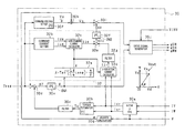
- FIG. 1 is a circuit diagram of a control apparatus for controlling a motor-generator according to the first embodiment of the present disclosure
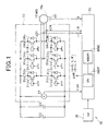
- FIG. 2 is a block diagram schematically illustrating an example of the specific structure of a controller of the control apparatus according to the first embodiment
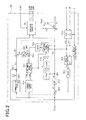
- FIG. 3 is a graph schematically illustrating a correlation between torque of the motor-generator and a phase of an output voltage vector of an inverter illustrated in FIG. 1 , referred to as a voltage phase;
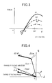
- FIG. 4 is a graph schematically illustrating change of a current vector depending on an infinitesimal change of the voltage phase, and change of the current vector as a result of an infinitesimal change of the amplitude of the output voltage vector;
- FIG. 5 is a graph, which is an enlarged view of the change the current vector depending on the infinitesimal change of the voltage phase illustrated in FIG. 4 ;
- FIG. 6 is a graph schematically illustrating an ⁇ -axis extending perpendicularly with respect to the changing direction of the current vector according to the first embodiment
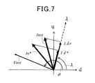
- FIG. 7 is a graph schematically illustrating a ⁇ -axis command current in a d-q-coordinate system according to the first embodiment
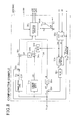
- FIG. 8 is a block diagram schematically illustrating an example of the specific structure of a controller of a control apparatus for controlling a motor-generator according to a comparative example
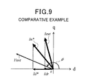
- FIG. 9 is a graph schematically illustrating a d-axis command current in a d-q-coordinate system according to the comparative example.
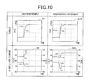
- FIG. 10 is a diagram showing an advantage of improvement of current control accuracy achieved by the control apparatus according to the first embodiment as a result of comparison with respect to the control apparatus according to the comparative example;
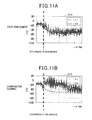
- FIGS. 11A and 11B are graphs cooperatively showing an advantage of improvement of current control accuracy in view of the occurrence of a disturbance achieved by the control apparatus according to the first embodiment as a result of comparison with respect to the control apparatus according to the comparative example;
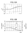
- FIGS. 12A and 12B are graphs cooperatively showing a correlation between the voltage phase and d- and q-axis currents
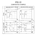
- FIG. 13 is a diagram schematically illustrating how torque ripples occur for the control apparatus according to the comparative example
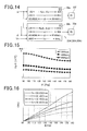
- FIG. 14 is a block diagram schematically illustrating an amplitude gain setter and a phase gain setter of a controller of a control apparatus according to the second embodiment of the present disclosure
- FIG. 15 is a graph schematically illustrating a relationship among an electric angular velocity of a rotor of the motor-generator, the voltage phase, and a proportional gain according to the second embodiment
- FIG. 16 is a graph schematically illustrating a relationship between the voltage phase and torque according to the second embodiment
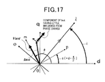
- FIG. 17 is a graph schematically illustrating a correlation between the d-q coordinate system and a p-m coordinate system according to the third embodiment of the present disclosure
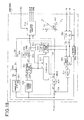
- FIG. 18 is a block diagram schematically illustrating an example of the specific structure of a controller of a control apparatus according to the third embodiment
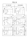
- FIG. 19 is a diagram showing an advantage of improvement of current control accuracy achieved by the control apparatus according to the third embodiment as a result of comparison with respect to the control apparatus according to the first embodiment;
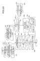
- FIG. 20 is a block diagram schematically illustrating an example of the specific structure of a controller of a control apparatus according to the fourth embodiment
- FIG. 21 is a flowchart schematically illustrating an inverter control routine carried out by the controller illustrated in FIG. 20 ;
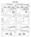
- FIG. 22 is a view showing advantages achieved by the control apparatus according to the fourth embodiment as a result of comparison with respect to a control apparatus according to a second comparative example;
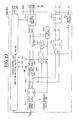
- FIG. 23 is a block diagram schematically illustrating an example of the specific structure of a controller of a control apparatus according to the fifth embodiment.
- FIG. 24 is a flowchart schematically illustrating an inverter control routine carried out by the controller illustrated in FIG. 23 .
- motor-generator 10 installed in a target vehicle as an example of rotary machines according to the present disclosure.
- motor-generator 10 a motor having a salient-pole structure is used as the motor-generator 10 .
- IPMSM interior permanent magnet synchronous motor
- FIG. 1 there is also illustrated a control system 50 .
- the control system 50 is equipped with an inverter 20 serving as a power converter, a high-voltage battery 22 serving as a DC power supply, a smoothing capacitor 24 , a control system 26 , and a control apparatus CA.
- the motor-generator 10 and the high-voltage battery 12 can establish electrical connection therebetween via the inverter 20 .
- the motor-generator 10 is provided with an annular rotor 10 a having an iron rotor core and rotatably disposed in the motor-generator 10 .
- the iron rotor core is, for example, directly or indirectly coupled to a crankshaft of an engine installed in the target vehicle to be rotatable together with the crankshaft.
- the rotor 10 a has a salient-pole structure.
- the rotor core of the rotor 10 a is specifically provided at its circumferential portions with at least one pair of permanent magnets.
- the permanent magnets of the at least one pair are so embedded in the outer periphery of the rotor core as to be symmetrically arranged with respect to the center axis of the rotor core at regular intervals in a circumferential direction of the rotor core.
- One permanent magnet of the at least one pair has a north pole (N pole) directed radially outward away from the center of the rotor core.
- the other permanent magnet has a south pole (S pole) directed radially outward away from the center of the rotor core.
- the rotor 10 a has a direct axis (d-axis) in line with a direction of magnetic flux created by the N pole, in other words, in line with an N-pole center line.
- the rotor 10 a also has a quadrature axis (q-axis) with a phase being ⁇ /2-radian electrical angle leading with respect to a corresponding d-axis during rotation of the rotor 10 a .
- the q-axis is electromagnetically orthogonal to the d-axis.
- the d and q axes constitute a d-q coordinate system, i.e. a two-phase rotating coordinate system, defined relative to the rotor 10 a of the motor-generator 10 .
- An inductance Ld in the d-axis is lower than an inductance Lq in the q-axis because the permanent magnets have a magnetic permeability constant lower than that of the iron.
- Motors having a salient-pole structure means motors each having this inductance characteristic of the rotor 10 a.
- the motor-generator 10 is also provided with a stator.
- the stator includes a stator core with, for example, an annular shape in its lateral cross section.
- the stator core is disposed around the outer periphery of the rotor core such that the inner periphery of the stator core is opposite to the outer periphery of the rotor core with a predetermined air gap.
- the stator core also has a plurality of slots.
- the slots are formed through the stator core and are circumferentially arranged at given intervals.
- the stator also includes a set of three-phase windings, i.e. armature windings, wound in the slots of the stator.
- the three-phase windings i.e. U-, V-, and W-phase windings, are wound in the slots such that the U-, V-, and W-phase windings are shifted, i.e. offset, by an electrical angle of, for example, 2 ⁇ /3 radian in phase from each other.
- the three-phase armature windings i.e. U-, V-, and W-phase windings, each have one end connected to a common junction, i.e. a neutral point, and the other end to a separate terminal in, for example, a star-configuration.
- the motor-generator 10 is operative to receive, at each of the three-phase windings, one of the three phase currents to thereby generate a rotating magnetic flux; this allows the rotor 10 a to turn based on magnetic attractive force between the rotating magnetic flux and a magnetic flux of the rotor 10 a.
- the high-voltage battery 22 is capable of outputting a voltage equal to or higher than 100 V.
- the smoothing capacitor 24 is disposed between the high-voltage battery 22 and the inverter 20 .
- the smoothing capacitor 24 is operative to smooth the output voltage from the high-voltage battery 22 , and supply the smoothed output voltage to the inverter 20 as input voltage.
- the inverter 20 is designed as a three-phase inverter.
- the inverter 20 is provided with a first pair of series-connected upper- and lower-arm (high- and low-side) switching elements SUp and SUn, a second pair of series-connected upper- and lower-arm switching elements SVp and SVn, and a third pair of series-connected upper- and lower-arm switching elements SWp and SWn.
- the inverter 20 is also provided with flywheel diodes DUp, DUn, DVp, DVn, DWp, and DWn electrically connected in antiparallel to the respective switching elements SUp, SUn, SVp, SVn, SWp, and SWn.
- the first to third pairs of switching elements are parallely connected to each other in bridge configuration.
- a connection point through which the switching elements SUp and SUn of the first pair are connected to each other in series is connected to an output lead extending from the separate terminal of the U-phase winding.
- a connection point through which the switching elements SVp and SVn of the second pair are connected to each other in series is connected to an output lead extending from the separate end of the V-phase winding.
- a connection point through which the switching elements SWp and SWn of the third pair are connected to each other in series is connected to an output lead extending from the separate end of the W-phase winding.
- One end of the series-connected switching elements of each of the first, second, and third pairs is connected to the positive terminal of the high-voltage battery 22 via a positive terminal of the inverter 20 .
- the other end of the series-connected switching elements of each of the first, second, and third pairs is connected to the negative terminal of the high-voltage battery 22 via a negative terminal of the inverter 20 .
- the control system 50 also includes current sensors 42 V and 42 W, a voltage sensor 44 , and a rotational angle sensor 46 .
- the current sensor 42 V is arranged to allow measurement of an instantaneous V-phase alternating current iv actually flowing through the V-phase winding of the stator.
- the current sensor 42 W is arranged to allow measurement of an instantaneous W-phase alternating current iw actually flowing through the W-phase winding of the stator.
- the current sensors 42 V and 42 W are communicable with the control apparatus CA.
- Each of the current sensors 42 V and 42 W is operative to send, to the control apparatus CA, the instantaneous value of a corresponding one of the V-, and W-phase alternating currents.
- the voltage sensor 44 is arranged to allow measurement of the input voltage, referred to as an input voltage VINV, to be supplied to the inverter 20 from the high-voltage power source 22 via the smoothing capacitor 24 .
- the voltage sensor 42 is communicable with the control apparatus CA, and operative to send, to the control apparatus CA, the input voltage VINV.
- the rotational angle sensor 46 includes, for example, a resolver.
- the rotational angle sensor 46 is configured to measure, i.e. monitor, a rotational angle, i.e. an electrical rotational angle, ⁇ of the rotor 10 a of the motor-generator 10 ; the rotational angle ⁇ of the rotor 10 a of the motor-generator 10 represents a rotational angle of the d-axis of the rotor 10 a .
- the rotational angle sensor 46 is communicable with the control apparatus CA, and operative to send, to the control apparatus CA, the monitored rotation angle ⁇ of the rotor 10 a.
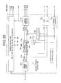
- the control apparatus CA includes drivers Dr ⁇ # and a controller 30 .
- the drivers Dr ⁇ # are connected to the control terminals of the respective switching elements S ⁇ #, and to the controller 30 .
- the controller 30 is designed as, for example, a computer circuit including essentially of for example, a CPU 30 CP and a memory 30 ME serving as, for example, a storage according to the present disclosure.
- the controller 30 is connected to the control system 26 for inputting, to the control apparatus CA, request torque, i.e. command torque, Trq* for the motor-generator 10 .
- request torque i.e. command torque
- Trq* command torque
- a controller which is higher in hierarchy than the controller 30 , can be used as the control system 26 if the controllers are arranged in a hierarchical relationship.
- the controller 30 is designed to receive the measured values output from the sensors 42 V, 42 W, 44 , and 46 , and the request torque Trq* as received pieces of data. Then, the controller 30 is designed to periodically generate, based on the received pieces of data set forth above, drive signals, i.e. pulse-width modulated (PWM) signals, g ⁇ # for individually driving the respective switching elements S ⁇ # of the inverter 20 .
- PWM pulse-width modulated
- the controller 30 is designed to supply the drive signals g ⁇ # to the respective drivers Dr ⁇ #.
- the drivers Dr ⁇ # are operative to output the drive signals g ⁇ # to the control terminals of the respective switching elements S ⁇ # of the inverter 20 .
- the drive signals g ⁇ # aim to switch the respective switching elements S ⁇ # to feedback control at least one controlled variable, such as torque, generated by the motor-generator 10 so that the at least one controlled variable matches the request torque Trq*.
- the controller 30 outputs the drive signals g ⁇ # that complementarily turns on the upper- and lower-arm switching elements S ⁇ p and S ⁇ n of each pair while dead times during which the upper- and lower-arm switching elements S ⁇ p and S ⁇ n are simultaneously turned off are ensured. Introducing the dead time prevents the upper and lower-arm switching elements S ⁇ p and S ⁇ n from being simultaneously on.
- Each of the drive signals g ⁇ # has a predetermined duty factor, i.e. a controllable on-pulse width for each switching cycle, in other words, a predetermined ratio, i.e. percentage, of on duration to the total duration of each switching cycle for a corresponding one of the switching elements S ⁇ #.
- a predetermined duty factor i.e. a controllable on-pulse width for each switching cycle
- a predetermined ratio i.e. percentage
- controller 30 for performing torque control i.e. torque feedback control, including amplitude control and phase control will be described with reference to FIG. 2 .
- the controller 30 includes a two-phase converter 30 a , a torque estimator 30 b , a filter 30 c , a torque deviation calculator 30 d , a phase setter 30 e , a command voltage setter 30 f , a velocity multiplier 30 h , a corrector 30 i , a drive signal generator 30 j , and a correction calculator 32 .
- the modules 30 a to 30 j and 32 cooperatively operate to carry out the torque control including the phase control and the amplitude control described in detail hereinafter.
- the modules 30 a to 30 j and 32 can be implemented as hardware modules, software modules, and hardware-software hybrid modules.
- the two-phase converter 30 a receives instantaneous V- and W-phase currents Iv and Iw measured by the respective current sensors 42 V and 42 W and the rotational angle ⁇ of the d-axis of the rotor 10 a measured by the rotational angle sensor 46 .
- the two-phase converter 30 a which serves as, for example, an actual current calculator, calculates an instantaneous U-phase current Iu based on the instantaneous V- and W-phase currents Iv and Iw in accordance with Kirchhoff's law. Then, the two-phase converter 30 a converts the instantaneous U-, V-, and W-phase currents Iu, Iv, and Iw in a three-phase fixed-coordinate system into d- and q-axis currents Idr and Iqr in the d-q coordinate system of the rotor 10 a based on the rotational angle ⁇ of the rotor 10 a .
- the stator coordinate system is fixedly defined relative to the stator; the stator coordinate system has fixed three axes corresponding to the three-phase windings of the stator.
- the two-phase converter 30 a performs the conversion using correlations between the d-q coordinate system and the stator coordinate system as a function of the rotational angle ⁇ .
- the torque estimator 30 b is operatively connected to the two-phase converter 30 a .
- the torque estimator 30 b is operative to calculate estimated torque Te for torque actually created by the motor-generator 10 based on the d-axis and q-axis currents Idr and Iqr input from the two-phase converter 30 a.
- the torque estimator 30 b calculates the estimated torque Te using, for example, information F 1 including a map in data-table format and/or one or more model equations.
- the map which is for example stored in the memory 30 ME, includes a function, i.e. correlation, of values of the estimated torque Te with respect to the pair of values of the d-axis current Idr, and values of the q-axis current Iqr.
- the torque estimator 30 b can retrieve a value of the estimated torque Te corresponding to values of the d-axis and q-axis currents Idr and Iqr in the map.
- the one or more model equations are defined based on variables of the d-axis and q-axis currents Idr and Iqr.
- the torque estimator 30 b can assign values of the d-axis and q-axis currents Idr and Iqr to the one or more model equations, thus calculating estimated torque Te.
- the filter 30 c is operatively connected to the torque estimator 30 b , and is designed as, for example, a low-pass filter that eliminates high-frequency components, which are higher than a predetermined threshold frequency, from the estimated torque Te calculated by the torque estimator 30 b .
- a value of the estimated torque Te, from which the high-frequency components have been eliminated, will be referred to as corrected estimated torque Te hereinafter.
- the torque deviation calculator 30 d is operatively connected to the filter 30 c , and subtracts the corrected estimated torque Te from the request torque Trq* to thereby calculate a torque deviation ⁇ T between the corrected estimated torque Te and the request torque Trq*.
- the phase setter 30 e is operatively connected to the torque deviation calculator 30 d .
- the phase setter 30 e sets, i.e. calculates, based on the torque deviation ⁇ T, a phase ⁇ of an output voltage vector Vnvt of the inverter 20 in the d-q coordinate system. That is, the phase ⁇ of the output voltage vector Vnvt serves as a manipulated variable for feedback controlling the corrected estimated torque Te to match with the request torque Trq*.
- the voltage vector Vnvt has a d-axis voltage component Vd and a q-axis voltage component Vq in the d-q coordinate system (see FIG. 2 ).
- the phase setter 30 e calculates the phase ⁇ of the output voltage vector Vnvt in accordance with a predetermined proportional gain Kp ⁇ and a predetermined integral gain Ki ⁇ , i.e. feedback gains Kp ⁇ and Ki ⁇ , of a proportional-integral (PI) feedback control algorithm (PI algorithm) using the torque deviation ⁇ T as its input.
- PI proportional-integral
- the phase ⁇ of the output voltage vector Vnvt is expressed based on the sum of an output ⁇ p, i.e. a proportional gain term, of a proportional unit based on the proportional gain Kp ⁇ and an output ⁇ i, i.e. an integral gain term, of an integrator IN 1 based on the integral gain Ki ⁇ .
- the proportional gain Kp ⁇ for the phase ⁇ of the output voltage vector Vnvt contributes to change in the phase ⁇ of the output voltage vector Vnvt in proportion to the temporal torque deviation ⁇ T from a target value of zero.
- the integral gain Ki ⁇ is proportional to an accumulated offset of instantaneous values of the torque deviation ⁇ T over time to reset the accumulated offset (steady-state deviation) over time to zero.
- proportional gain Kp ⁇ simulations and/or experiments using, for example, the control apparatus 50 have been performed, so that a constant value has been determined to be set to the proportional gain Kp ⁇ .
- the constant value of the proportional gain Kp ⁇ will also be referred to as a basic proportional gain hereinafter.
- integral gain Ki ⁇ simulations and/or experiments using, for example, the control apparatus 50 have been performed, so that a constant value has been determined to be set to the integral gain Ki ⁇ .
- the constant value of the integral gain Ki ⁇ will also be referred to as a basic integral gain hereinafter.
- the phase ⁇ of the output voltage vector Vnvt which will be referred to as a voltage phase ⁇ , is defined such that a counter clockwise rotational direction from the positive side of the d-axis toward the positive side of the q-axis represents the positive direction of the voltage phase ⁇ (see FIG. 2 ).
- the phase setter 30 e advances, in accordance with the definition of the voltage phase ⁇ , the voltage phase ⁇ when the corrected estimated torque Te is lower than the request torque Trq*.
- the phase setter 30 e also delays, in accordance with the definition of the voltage phase ⁇ , the voltage phase ⁇ when the corrected estimated torque Te is higher than the request torque Trq*.
- FIG. 3 also illustrates that the torque generated by the motor-generator 10 depends on the rotational speed, i.e. the electrical angular velocity ⁇ , of the rotor 10 a of the motor-generator 10 .
- the command-voltage setter 30 f has, for example, information F 2 in data-table (map) format, in mathematical expression format, and/or program format.
- the information F 2 which is for example stored in the memory 30 ME, includes a function, i.e. a correlation, of values of a normalized amplitude Vn/ ⁇ of the output voltage vector Vnvt in the d-q coordinate system with respect to values of the request torque Trq*.
- the amplitude Vn of the output voltage vector Vnvt of the inverter 20 is defined as the square root of the sum of the square of the d-axis voltage component Vd and the square of the q-axis voltage component Vq of the output voltage vector Vnvt.
- the normalized amplitude Vn/ ⁇ of the output voltage vector Vnvt represents division of the command value of the amplitude Vn of the output voltage vector Vnvt from the inverter 20 by the electrical angular velocity ⁇ of the rotor 10 a.
- the velocity calculator 30 g is operatively connected to the command-voltage setter 30 f , and calculates the electrical angular velocity ⁇ of the rotor 10 a based on the rotational angle ⁇ of the rotor 10 a measured by the rotational angle sensor 46 .
- the velocity multiplier 30 h is operatively connected to the command-voltage setter 30 f and to the velocity calculator 30 g , and multiplies the normalized command-voltage amplitude Vn/ ⁇ by the electrical angular velocity ⁇ . This multiplication calculates a value of the amplitude Vn of the output voltage vector Vnvt.
- the value of the amplitude Vn of the output voltage vector Vnvt serves as a manipulated variable for feedforward controlling the torque of the motor-generator 10 to match with the request torque Trq*.
- the corrector 30 i is operatively connected to the velocity multiplier 30 h , and adds, to the value of the amplitude Vn of the output voltage vector Vnvt output from the velocity multiplier 30 h , an amplitude correction ⁇ V calculated by the correction calculator 32 .
- This addition calculates the sum of the value of the amplitude Vn of the output voltage vector Vnvt and the amplitude correction ⁇ V, as a correction value of the value of the amplitude Vn of the output voltage vector Vnvt.
- the sum of the value of the amplitude Vn of the output voltage vector Vnvt and the amplitude correction ⁇ V will be referred to as a corrected voltage amplitude (Vn+ ⁇ V) hereinafter. Detailed operations of the correction calculator 32 will be described later.
- the drive signal generator 30 j is operatively connected to the phase setter 30 e and the corrector 30 i .
- the drive signal generator 30 j which serves as, for example, a switching unit, calculates a modulation factor M based on normalization of the input voltage VINV using the value of the voltage amplitude Vn. Specifically, the drive signal generator 30 j divides the value of the voltage amplitude Vn by half of the input voltage VINV to obtain a quotient, and divides the quotient by ⁇ square root over (1.5) ⁇ , i.e.
- the drive signal generator 30 j When the modulation factor M becomes a value equal to or smaller than a first specified value Ma of, for example, 1.15, the drive signal generator 30 j generates the drive signals g ⁇ # in accordance with sinusoidal PWM control.
- the drive signal generator 30 j converts the voltage amplitude Vn and the phase ⁇ of the output voltage vector Vnvt into a command d-axis voltage Vd* and a command q-axis voltage Vq*. Then, the drive signal generator 30 j transforms, based on the rotational angle ⁇ of the rotor 10 a , the command d- and q-axis voltages Vd* and Vq* into three-phase sinusoidal command voltages that are shifted by an electrical angle of 2 ⁇ /3 radian, i.e. 120 electrical degrees, in phase from each other.
- the drive signal generator 30 j compares in amplitude each of the three-phase sinusoidal command voltages with a carrier signal, such as a triangular carrier signal, which has an amplitude predetermined based on an amplitude of each of the three-phase sinusoidal command voltages, thus generating the drive signals g ⁇ #.
- the drive signals g ⁇ # control on and off operations of the switching elements S ⁇ #, thus causing the output voltage, i.e. a line-line voltage, of the inverter 20 to have a pseudo sinusoidal waveform with the electrical angular velocity ⁇ .
- the drive signal generator 30 j When the modulation factor M becomes a value greater than the first specified value Ma and smaller than a second specified value Mb of, for example, 1.27, that is greater than the first specified value Ma, the drive signal generator 30 j generates the driving signals g ⁇ # based on the torque control including the amplitude control and the phase control set forth above.
- the torque control i.e. torque feedback control, including the amplitude control and the phase control will be referred to as an over-modulation torque control, in other words, an over-modulation torque feedback control.
- the drive signal generator 30 j converts the corrected voltage amplitude (Vn+ ⁇ V) and the phase ⁇ of the output voltage vector Vnvt into a command d-axis voltage Vd* and a command q-axis voltage Vq*. Then, the drive signal generator 30 j transforms, based on the rotational angle ⁇ of the rotor 10 a , the command d- and q-axis voltages Vd* and command q-axis voltage Vq* into three-phase sinusoidal command voltages that are shifted by an electrical angle of 2 ⁇ /3 radian in phase from each other.
- the amplitude of each of the three-phase sinusoidal command voltages in the over-modulation torque control is higher than the amplitude of the carrier signal.
- the drive signal generator 30 j compares in amplitude each of the three-phase sinusoidal command voltages with a carrier signal, such as a triangular carrier signal, which has an amplitude predetermined based on an amplitude of each of the three-phase sinusoidal command voltages, thus generating the drive signals g ⁇ #.
- the drive signals g ⁇ # control on and off operations of the switching elements S ⁇ #, thus causing the output voltage, i.e. the line-to-line voltage, of the inverter 20 , which is applied to the motor-generator 10 , to have a distorted sinusoidal waveform.
- a fundamental component of the output voltage of the inverter 20 in the over-modulation torque control has an amplitude and a root-mean-square (rms) value greater than respective amplitude and an rms value of a fundamental component of the output voltage of the inverter 20 for the sinusoidal PWM control.
- the drive signal generator 30 j when the modulation factor M becomes equal to or greater than the second specified value Mb, the drive signal generator 30 j generates the driving signals g ⁇ # based on rectangular-pulse torque control including the phase control.
- the modulation factor M becomes equal to or greater than the second specified value Mb
- the amplitude of the output voltage of the inverter 20 is fixed to the input voltage VINV.
- the drive signals g ⁇ # generates on-off pulse patterns of the switching elements S ⁇ # such that the ratio of an on duration to an off duration for each of the switching elements S ⁇ # are set to 1:1 every period of the electrical rotational angle ⁇ of the rotor 10 a.
- R represents the resistance of each-phase armature winding
- Ld represents the inductance in the d-axis
- Lq represents the inductance in the q-axis
- ⁇ represents an rms value of permanent-magnet flux linkage to each-phase armature winding.
- a steady state of the motor-generator 10 in which the rpm of the rotor 10 a is kept constant, permits a transient state of the motor-generator 10 to be ignorable, resulting in the value of the differential operator p being set to zero.
- the steady state of the motor-generator 10 it is assumed that the following conditions are satisfied:
- the rpm of the rotor 10 a of the motor-generator 10 is a sufficiently high value
- a voltage equation of a permanent-magnet synchronous motor when the voltage phase ⁇ changes by an infinitesimal value ⁇ is expressed by the following equation [eq4] based on the equations [eq2] and [eq3]:
- Vd ⁇ ⁇ ⁇ - Vd Vq ⁇ ⁇ ⁇ - Vq ] [ 0 - ⁇ ⁇ Lq ⁇ ⁇ L ⁇ ⁇ d 0 ] ⁇ [ Id ⁇ ⁇ ⁇ - Idr Iq ⁇ ⁇ ⁇ - Iqr ] [ eq5 ]
- FIG. 4 illustrates the voltage vector Vnvt having the voltage phase ⁇ and a current vector Invt based on the voltage vector Vnvt.
- a current vector Invt is defined as the square root of the sum of the square of a d-axis current Idr and the square of a q-axis current Iqr.
- FIG. 4 also illustrates change of the current vector Invt depending on an infinitesimal change ⁇ of the voltage phase ⁇ using reference character ⁇ I ⁇ .
- FIG. 4 further illustrates change of the current vector Invt depending on an infinitesimal change ⁇ Vn of the amplitude Vn of the output voltage vector Vnvt using reference character ⁇ Ivn.
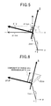
- FIG. 5 is an enlarged view of the change ⁇ I ⁇ of the current vector Invt depending on the infinitesimal change ⁇ of the voltage phase ⁇ .
- the equation [eq6] permits the change direction a of the current vector Invt with respect to the d-axis depending on the infinitesimal change ⁇ of the voltage phase ⁇ to be expressed by the following equation [eq7]:
- FIG. 5 shows that the arctangent operation in the equation [eq7] permits the change direction ⁇ of the current vector Invt with respect to the d-axis to be calculated between ⁇ and + ⁇ inclusive.
- the controller 30 particularly calculates the change direction ⁇ of the current vector Invt with respect to the d-axis as + ⁇ /2 when the denominator of
- the controller 30 also calculates the change direction ⁇ of the current vector Invt with respect to the d-axis as ⁇ /2 when the denominator of
- FIG. 6 illustrates a coordinate axis, which is referred to as a ⁇ -axis, extending perpendicularly with respect to the changing direction of the current vector Invt.
- a ⁇ -axis component of the change ⁇ Ivn of the current vector Invt depending on the infinitesimal change ⁇ Vn of the amplitude Vn of the output voltage vector Vnvt means a component of the change ⁇ Ivn of the current vector Invt projected on the ⁇ -axis.
- the ⁇ -axis component of the change ⁇ Ivn of the current vector Invt illustrated in FIG. 6 is a current independent from change of the voltage phase ⁇ .
- the correction calculator 32 is designed to use the ⁇ -axis component of the change ⁇ Ivn of the current vector Invt for calculation of the amplitude correction ⁇ V.
- Using the ⁇ -axis component of the change ⁇ Ivn of the current vector Invt permits interference between the amplitude control and the phase control to be reduced.
- the angle ⁇ between the d-axis and the X-axis, which is required to set the ⁇ -axis, is expressed by the following equation [eq8]:
- the correction calculator 32 includes a ⁇ -axis setter 32 a , a command current setter 32 b , a ⁇ -axis command current calculator 32 c , a ⁇ -axis actual current calculator 32 d , a current deviation calculator 32 e , an amplitude correction calculator 32 f , and a filter 32 g.
- the ⁇ -axis setter 32 a is operatively connected to the phase setter 30 e .
- the ⁇ -axis setter 32 a which serves as, for example, an interference-reduction coordinate axis setter, calculates, based on the d- and q-axis inductances Ld and Lq, the voltage phase ⁇ output from the phase setter 30 e , the angle ⁇ between d-axis and the ⁇ -axis in accordance with the equation [eq8].
- the ⁇ -axis setter 32 a serves as means, i.e. a unit, for setting an interference reduction axis, i.e. a non-interference axis or an independent axis, in the d-q coordinate system. That is, the ⁇ -axis setter 32 a sets the ⁇ -axis.
- the ⁇ -axis is configured such that a component of change of the current vector Invt, which is projected on the ⁇ -axis, has reduced interferences, for example, no interferences or little interference, from change of the voltage phase ⁇ . In other words, the component of change of the current vector Invt projected on the ⁇ -axis is sufficiently free from interferences from change of the voltage phase ⁇ .
- the ⁇ -axis set by the ⁇ -axis setter 32 a changes depending on change of the driven conditions of the motor-generator 10 .
- the feature that the component of change of the current vector Invt, which is projected on the ⁇ -axis, causes reduced interferences from change of the voltage phase ⁇ can include that both
- the ⁇ -axis allows a minimum level of interference from change of the voltage phase ⁇ unless the minimum level of interference reduces the controllability of the controlled variable, such as the estimated torque Te, of the motor-generator 10 .
- the command current setter 32 b sets a d-axis command current Id* and a q-axis command current Iq* that carry out maximum torque control. Note that the maximum torque control is designed to always achieve a maximum torque at any value of the current vector Ivnt, in other words, most efficiently achieve the torque of the motor-generator 10 at any value of the current vector Ivnt.
- the command current setter 32 b sets the d-axis command current Id* and a q-axis command current Iq* in accordance with the following equation [eq8a]:
- the ⁇ -axis command current calculator 32 c is operatively connected to the ⁇ -axis setter 32 a and the command current setter 32 b .
- FIG. 7 illustrates an actual command current vector In* having the d- and q-axis axis command currents Id* and Iq*, and a present current vector Ivnt having a d-axis current Idr and a q-axis current Iqr actually obtained by the two-phase converter 30 a.
- the ⁇ -axis actual current calculator 32 d is operatively connected to the two-phase converter 30 a and the ⁇ -axis setter 32 a .
- the filter 32 g is operatively connected to the ⁇ -axis actual current calculator 32 d , and is designed as, for example, a low-pass filter that eliminates high-frequency components higher than a predetermined threshold frequency from the ⁇ -axis current I ⁇ r actually obtained by the ⁇ -axis actual current calculator 32 d .
- a value of the ⁇ -axis current I ⁇ r, from which the high-frequency components have been eliminated, will be referred to as a corrected ⁇ -axis current I ⁇ r hereinafter.
- the current deviation calculator 32 e is operatively connected to the filter 32 g and the ⁇ -axis command current calculator 32 c .
- the current deviation calculator 32 e subtracts the corrected ⁇ -axis current I ⁇ r from the ⁇ -axis command current I ⁇ * to thereby calculate a current deviation ⁇ I ⁇ between the corrected ⁇ -axis current I ⁇ r and the ⁇ -axis command current i ⁇ *.
- the amplitude correction calculator 32 f is operatively connected to the current deviation calculator 32 e .
- the amplitude correction calculator 32 f which serves as, for example, an amplitude setter, calculates, based on the current deviation ⁇ I ⁇ , the amplitude correction ⁇ V serving as a manipulated variable for feedback controlling the corrected ⁇ -axis current I ⁇ r to match with the ⁇ -axis command current I ⁇ *, in other words, for feedback controlling the corrected estimated torque Te to match with the request torque Trq*.
- the amplitude correction calculator 32 f calculates the amplitude correction ⁇ V in accordance with a predetermined proportional gain Kp ⁇ and a predetermined integral gain Ki ⁇ of a PI feedback control algorithm (PI algorithm) using the current deviation ⁇ I ⁇ as its input.
- PI algorithm PI feedback control algorithm
- the amplitude correction ⁇ V is expressed based on the sum of an output ⁇ Vpro, i.e. a proportional gain term, of a proportional unit based on the proportional gain Kp ⁇ and an output ⁇ Vi, i.e. an integral gain term, of an integrator IN 2 based on the integral gain Ki ⁇ .
- the proportional gain Kp ⁇ for the amplitude correction ⁇ V contributes to change in the amplitude correction ⁇ V in proportion to the temporal current deviation ⁇ I ⁇ from a target value of zero.
- the integral gain Ki ⁇ is proportional to an accumulated offset of instantaneous values of the current deviation ⁇ I ⁇ over time to reset the accumulated offset (steady-state deviation) over time to zero.
- proportional gain Kp ⁇ simulations and/or experiments using, for example, the control apparatus 50 have been performed, so that a constant value has been determined to be set to the proportional gain Kp ⁇ .
- the constant value of the proportional gain Kp ⁇ will also be referred to as a basic proportional gain hereinafter.
- integral gain Ki ⁇ simulations and/or experiments using, for example, the control apparatus 50 have been performed, so that a constant value has been determined to be set to the integral gain Ki ⁇ .
- the constant value of the integral gain Ki ⁇ will also be referred to as a basic integral gain hereinafter.
- controller 30 X the structure of the controller 30 X according to the comparative example will be described hereinafter with reference to FIG. 8 .
- the controller 30 X includes a correction calculator 34 .
- the correction calculator 34 includes a command current setter 34 a , a current deviation calculator 34 b , an amplitude correction calculator 34 c , and a filter 34 d.
- the command current setter 34 a has the same function as the function of the command current setter 32 b .
- the filter 34 d is operatively connected to the two-phase converter 30 a , and is designed as, for example, a low-pass filter that eliminates high-frequency components higher than a predetermined threshold frequency from the d-axis current Idr obtained by the two-phase converter 30 a .
- a value of the d-axis current Idr, from which the high-frequency components have been eliminated, will be referred to as a corrected d-axis current Idr hereinafter.
- the current deviation calculator 34 b is operatively connected to the command current setter 34 a and the filter 34 d .
- the current deviation calculator 34 b subtracts the corrected d-axis current Idr from the d-axis command current Id* to thereby calculate a current deviation ⁇ Id between the corrected d-axis current Idr and the d-axis command current Id*.
- the amplitude correction calculator 34 c is operatively connected to the current deviation calculator 34 b .
- the amplitude correction calculator 34 c calculates, based on the current deviation ⁇ Id, the amplitude correction ⁇ V serving as a manipulated variable for feedback controlling the corrected d-axis current Idr to match with the d-axis command current Id*, in other words, for feedback controlling the corrected estimated torque Te to match with the request torque Trq* (see FIG. 9 ).
- FIG. 10 schematically illustrates
- reference character Id represents a collective term subsuming an actual d-axis current Idr and a d-axis command current Id*
- reference character Iq represents a collective term subsuming an actual q-axis current Iqr and a q-axis command current Iq*.
- the scales of the vertical axes of the respective graphs G 1 , G 2 , G 1 A, and G 2 A are identical to each other, and the scales of the horizontal axes of the respective graphs G 1 , G 2 , G 1 A, and G 2 A are identical to each other.
- calculation of the amplitude correction ⁇ V based on the ⁇ -axis current I ⁇ r in the ⁇ -axis reduces interference between the amplitude control and the phase control.
- This interference reduction permits the controller 30 according to the first embodiment to control the corrected d- and q-axis currents id and iq to match with the respective d- and q-axis command currents Id* and Iq* with a higher accuracy (see the graph G 2 ).
- the controller 30 X calculates the amplitude correction ⁇ V merely using the d-axis current Idr in the d-axis, yielding considerable interference between the amplitude control and the phase control. This considerable interference reduces the accuracy of controlling the corrected d- and q-axis currents idr and iqr to match with the respective d- and q-axis command currents Id* and Iq*, resulting in torque ripples in the second step response of the motor-generator 10 driven by the control system 50 X according to the comparative example.
- FIG. 11A is a graph G 11 schematically illustrating how the d-axis current Idr changes when a simulated disturbance having an influence on the voltage amplitude Vn is applied to the voltage amplitude Vn output from the corrector 30 i according to the first embodiment.
- FIG. 11B is a graph G 12 schematically illustrating how the d-axis current Idr changes when the same simulated disturbance is applied to the voltage amplitude Vn output from the corrector 30 i according to the comparative example.
- Such disturbances having an influence on the voltage amplitude Vn include, for example, fluctuations of the input voltage VINV to the inverter 20 , and variations of the dead times included in the drive signals g ⁇ #.
- the scales of the vertical and horizontal axes of the graph G 11 are identical to those of the respective vertical and horizontal axes of the graph G 12 .
- FIG. 11A shows that reduction in the interference between the amplitude control and the phase control controls the corrected d-axis current id to match with the d-axis command current Id* with a higher accuracy even if the simulated disturbance is applied to the voltage amplitude Vn. This results in no ripples in the torque of the motor-generator 10 driven by the control system 50 according to the first embodiment.
- FIG. 11B shows that considerable interference yielded between the amplitude control and the phase control reduces the accuracy of controlling the corrected d-axis current id to match with the d-axis command current Id*, resulting in ripples in the torque of the motor-generator 10 driven by the control system 50 X according to the comparative example.
- the over-modulation control range is defined as an operation range of the inverter 20 in which the modulation factor M is greater than the first specified value Ma of, for example, 1.15 and smaller than the second predetermined value of, for example, 1.27.
- an operation range of the inverter 20 in which the modulation factor M is equal to or smaller than the first specified value Ma is defined as a sinusoidal PWM control range.
- an operation range of the inverter 20 in which the modulation factor M is equal to or greater than the second specified value Mb is defined as a rectangular-pulse control range.
- the predetermined angular region of the voltage phase ⁇ close to 180 electrical degrees corresponds to a greatly-changed region of the d-axis current Idr.
- the controller 30 X illustrated in FIG. 8 causes an increase of interference between the amplitude control and the phase control. This increase of interference results in ripples in the torque of the motor-generator 10 according to the comparative example.
- FIG. 13 schematically illustrates
- the scales of the vertical axes of the respective graphs G 21 , G 22 , G 21 A, and G 22 A are identical to each other, and the scales of the horizontal axes of the respective graphs G 21 , G 22 , G 21 A, and G 22 A are identical to each other.
- the graph G 22 shows that using a lower value of each of the proportional gain and the integral gain of the amplitude correction calculator 34 c according to the comparative example reduces the controllability of each of the corrected d- and q-axis currents idr and iqr to match with the respective d- and q-axis command currents Id* and Iq*.
- the graph G 24 shows that using a higher value of each of the proportional gain and the integral gain of the amplitude correction calculator 34 c improves the controllability of each of the corrected d- and q-axis currents id and iq to match with the respective d- and q-axis command currents Id* and Iq* as compared to that illustrated in the graph G 22 .
- the graph G 23 shows that interference between the amplitude control and the phase control may yield ripples in the corrected estimated torque Te of the motor-generator 10 according to the comparative example.
- FIG. 13 demonstrates that the occurrence of torque ripples is unavoidable unless interference between the amplitude control and the phase control is reduced.
- the control apparatus 50 is configured to calculate the amplitude correction ⁇ V based on the ⁇ -axis current I ⁇ r in the ⁇ -axis, which is a non-interference axis having no or little interference from change of the voltage phase ⁇ .
- This configuration permits the proportional gain and the integral gain of the amplitude correction calculator 32 f to increase. This gain increase improves a response, i.e. a response performance, of the feedback control in the amplitude control up to a level identical to a level of the response of the feedback control in the phase control.
- This improvement permits the control apparatus 50 to maintain both higher controllability of the torque of the motor-generator 10 , and higher controllability of the three-phase currents flowing in the motor-generator 10 even if a disturbance having an influence on the voltage amplitude Vn occurs, or the request torque Trq* transiently changes.
- the configuration of the control apparatus 50 also maintains both higher controllability of the torque of the motor-generator 10 , and higher controllability of the three-phase currents flowing in the motor-generator 10 even if the feedforward control of the torque of the motor-generator 10 to match with the request torque Trq* is improperly carried out.
- the improperly execution of the feedforward control includes a case where the information F 2 used by the command-voltage setter 30 f is inappropriately determined.
- a control apparatus 50 A for the motor-generator 10 according to the second embodiment of the present disclosure will be described with reference to FIGS. 14 to 16 .
- control apparatus 50 A according to the second embodiment are different from the control apparatus 50 according to the first embodiment by the following points. So, the different points will be mainly described hereinafter.
- a controller 30 A of the control apparatus 50 A includes a correction calculator 32 A.
- the correction calculator 32 A further includes an amplitude gain setter 36 a and a phase gain setter 36 b in addition to the structure of the correction calculator 32 .
- the amplitude gain setter 36 a is operatively connected to the amplitude correction calculator 32 f , the phase setter 30 e , and the velocity calculator 30 g .
- the amplitude gain setter 36 a variably sets a value of at least one of a proportional gain Kpv and the integral gain Kiv, i.e. feedback gains Kpv and Kiv, used by the amplitude correction calculator 32 f according to the second embodiment in accordance with, for example, change of the electrical angular velocity ⁇ of the rotor 10 a and the voltage phase ⁇ .
- the phase gain setter 36 b is operatively connected to the phase setter 30 e , the velocity calculator 30 g , and the velocity multiplier 30 h .
- the phase gain setter 36 b variably sets a value of at least one of the proportional gain and the integral gain used by the phase setter 30 e in accordance with, for example, change of the electrical angular velocity ⁇ of the rotor 10 a , the voltage phase ⁇ fed back thereto from the phase setter 30 e , and the voltage amplitude Vn calculated by the velocity multiplier 30 h .
- the proportional gain and the integral gain used by the phase setter 30 e will be referred to as a proportional gain Kp ⁇ and an integral gain Ki ⁇ hereinafter.
- a voltage equation of a permanent-magnet synchronous motor when the voltage amplitude Vn changes by an infinitesimal value ⁇ Vn is expressed by the following equation [eq12] based on the equations [eq2] and [eq3]:
- the angle ⁇ included in the equation [eq15] is expressed by the equation [eq8].
- This causes the proportional gain Kp ⁇ to change depending on the voltage phase ⁇ and the rotational speed, i.e. the electrical angular velocity ⁇ , of the rotor 10 a (see FIG. 15 ).
- Executing the feedback control in the amplitude control using constant values of the respective proportional gain Kp ⁇ and integral gain Ki ⁇ irrespective of characteristic changes of the respective proportional gain Kp ⁇ and integral gain Ki ⁇ set forth above may cause variations in the response of the amplitude control as the driven state of the motor-generator 10 changes. This may result in relative reduction in the response of the amplitude control at some driven states of the motor-generator 10 .
- Maintaining, at a higher level, the response of the amplitude control even if the driven state of the motor-generator 10 changes requires variable setting of at least one of the respective proportional gain Kpv and integral gain Kiv used by the feedback control in the amplitude control.
- the amplitude gain setter 36 a variably sets at least one of the proportional gain Kpv and integral gain Kiv depending on change of the voltage phase ⁇ and the electrical angular velocity ⁇ .
- This variable set is designed to maintain, at a constant level, the response of the feedback control in the amplitude control even if the driven state of the motor-generator 10 changes.
- the amplitude gain setter 36 a increases at least one of the proportional gain Kpv and integral gain Kiv with an increase of the electrical angular velocity ⁇ and/or with the voltage phase ⁇ advancing (see FIG. 2 ).
- the design of maintaining, at a constant level, the response of the feedback control in the amplitude control is equivalent to the design of maintaining, within a target time, a time constant for the ⁇ -axis current I ⁇ r when the ⁇ -axis command current I ⁇ * transiently changes like a step without consideration of the feedforward system of the command voltage setter 30 f and the velocity calculator 30 h.
- the amplitude gain setter 36 a calculates the proportional gain Kp ⁇ and integral gain Ki ⁇ in the following method.
- the amplitude gain setter 36 a includes information F 3 including a map in data-table format and/or one or more model equations.
- the information F 3 which is for example stored in the memory 30 ME, includes a function, i.e. correlation, of values of the reciprocal of the proportional gain Kp ⁇ , illustrated in FIG. 15 with respect to values of the voltage phase ⁇ .
- the reciprocal of the proportional gain Kpv will be referred to as a correction gain.
- the amplitude gain setter 36 a retrieves a value of the correction gain, which matches with an actual value of the voltage phase ⁇ , and multiplies the basic proportional gain described in the first embodiment by the retrieved value of the correction gain, thus calculating a value of the proportional gain Kpv according to the second embodiment.
- the amplitude gain setter 36 a can set a value of the integral gain Kiv in the same approach as setting a value of the proportional gain Kpv.
- Idr 1 Ld ⁇ ( Vd ⁇ - ⁇ ) [ eq16a ]
- Iqr - Vd ⁇ ⁇ Ld [ eq16b ]
- Pn represents the number of pole pairs of the rotor 10 a of the motor-generator 10 .
- the equation [eq18] shows that the torque ⁇ of the motor-generator 10 changes depending on the voltage amplitude Vn, the voltage phase ⁇ , and electrical angular velocity w of the rotor 10 a (see FIG. 16 ).
- Executing the feedback control in the phase control using constant values of the respective proportional gain Kp ⁇ and integral gain Ki ⁇ irrespective of characteristic changes of the respective proportional gain Kp ⁇ and integral gain Ki ⁇ set forth above may cause variations in the response of the phase control as the driven state of the motor-generator 10 changes. This may result in relative reduction in the response of the amplitude control at some driven states of the motor-generator 10 . Maintaining, at a higher level, the response of the phase control even if the driven state of the motor-generator 10 changes requires variable setting of at least one of the respective proportional gain Kp ⁇ and integral gain Ki ⁇ used by the feedback control in the phase control.
- the phase gain setter 36 b variably sets at least one of the proportional gain Kp ⁇ and integral gain Ki ⁇ depending on change of the voltage amplitude Vn, the voltage phase ⁇ , and electrical angular velocity ⁇ of the rotor 10 a .
- This variable set makes it possible to maintain, at a constant level, the response of the feedback control in the phase control even if the driven state of the motor-generator 10 changes.
- the phase gain setter 36 b increases at least one of the proportional gain Kp ⁇ and integral gain Ki ⁇ with an increase of the electrical angular velocity ⁇ or a decrease of the voltage amplitude Vn, and/or with the voltage phase ⁇ retarding (see FIG. 2 ).
- Maintaining, at a constant level, the response of the feedback control in the phase control is equivalent to maintain, within a target time, a time constant for the corrected estimated torque Te when the request torque Trq* transiently changes like a step.
- phase gain setter 36 b calculates the proportional gain Kp ⁇ and integral gain Ki ⁇ in the following method.
- the phase gain setter 36 b includes information F 4 including a map in data-table format and/or one or more model equations.
- the information F 4 which is for example stored in the memory 30 ME, includes a function, i.e. correlation, of values of each of the gradients of the torque ⁇ of the motor-generator 10 illustrated in FIG. 16 with respect to values of the voltage phase ⁇ .
- the gradients are respectively determined based on the following driven conditions of the motor-generator 10 :
- the voltage amplitude Vn is set to 100, and the electrical angular velocity ⁇ is set to 2000 rpm
- the voltage amplitude Vn is set to 150, and the electrical angular velocity ⁇ is set to 4000 rpm.
- Each of the gradients corresponding to the prepared driven conditions of the motor-generator 10 will be referred to as a correction gain.
- the phase gain setter 36 b selects one of the correction gains, which matches with a corresponding one of the driven condition of the motor-generator 10 . Then, the phase gain setter 36 b retrieves a value of the selected correction gain of the torque ⁇ of the motor-generator 10 , which matches with an actual value of the voltage phase ⁇ . Successively, the phase gain setter 36 b multiplies each of the basic proportional gain and the basic integral gain described in the first embodiment by the retrieved value of the selected correction gain, thus calculating a value of the proportional gain Kp ⁇ and the integral gain Ki ⁇ according to the second embodiment.
- phase gain setter 36 b can set the proportional gain Kp ⁇ and the integral gain Ki ⁇ using methods of setting the proportional gain Kp ⁇ and the integral gain Ki ⁇ disclosed in Japanese Patent Application Publication No. 2012-085485.
- the disclosure of the Japanese Patent Application Publication No. 2012-085485 is incorporated entirely herein by reference.
- control apparatus 50 A is configured to
- This configuration maintains, at a higher level, the response performance of each of the amplitude control and the phase control independently of change of the driven conditions of the motor-generator 10 .
- a control apparatus 50 B for the motor-generator 10 according to the third embodiment of the present disclosure will be described with reference to FIGS. 17 to 19 .
- control apparatus 50 B according to the third embodiment are different from the control apparatus 50 according to the first embodiment by the following points. So, the different points will be mainly described hereinafter.
- a controller 30 B of the control apparatus 50 B includes a correction calculator 32 B.
- the design of the correction calculator 32 B differs from the design of the correction calculator 30 according to the first embodiment.
- a voltage equation of a permanent-magnet synchronous motor when the d- and q-axis voltage components Vd and Vq changes by respective infinitesimal values ⁇ Vd and ⁇ Vq is expressed by the following equation [eq20] based on the equation [eq19]:
- FIG. 17 schematically illustrates a new orthogonal coordinate system, i.e. a p-m coordinate system (p-m coordinate system).
- the p-m coordinate system has an m axis extending from the same origin 0 of the d-q coordinate system in parallel to the direction of the output voltage vector Vnvt, and a p axis extending from the origin 0 perpendicularly to the direction of the output voltage vector Vnvt.
- the p-m coordinate system changes depending on change of the driven conditions of the motor-generator 10 .
- An increase or decrease of the infinitesimal change ⁇ Vm is equivalent to an increase or decrease of the amplitude of the output voltage vector Vnvt
- an increase or decrease of the infinitesimal change ⁇ Vp is equivalent to an increase or decrease of the phase of the output voltage vector Vnvt.
- a sufficiently high value of the electrical angular velocity ⁇ establishes the following formulas Rc ⁇ Lo ⁇ and Rs ⁇ L ⁇ .
- a phase setter 30 k is operatively connected to the torque deviation calculator 30 d , and sets, i.e. calculates, based on the torque deviation ⁇ T, a p-axis voltage component Vp in the p-m coordinate system. That is, the p-axis voltage component Vp serves as a manipulated variable for feedback controlling the corrected estimated torque Te to match with the request torque Trq*.
- the p-axis voltage component Vp corresponds to a p-axis component of the output voltage vector Vnvt in the p-m coordinate system. That is, the p-axis voltage component Vp serves as a phase parameter depending on the voltage phase ⁇ .
- the phase setter 30 k calculates the p-axis voltage component Vp in accordance with a predetermined proportional gain and a predetermined integral gain, i.e. feedback gains, of a proportional-integral (PI) feedback control algorithm (PI algorithm) using the torque deviation ⁇ T as its input.
- PI proportional-integral
- the p-axis voltage component Vp is expressed based on the sum of an output, i.e. a proportional gain term, of a proportional unit based on the proportional gain and an output, i.e. an integral gain term, of an integrator IN 1 A based on the integral gain.
- the proportional gain for the p-axis voltage component Vp contributes to change in the p-axis voltage component Vp in proportion to the temporal torque deviation ⁇ T from a target value of zero.
- the integral gain is proportional to an accumulated offset of instantaneous values of the torque deviation ⁇ T over time to reset the accumulated offset (steady-state deviation) over time to zero.
- a command-voltage setter 30 l has, for example, information F5 in data-table (map) format, in mathematical expression format, and/or program format.
- the normalized voltage amplitude Vm/ ⁇ represents division of the command value of the m-axis voltage component Vm in the p-m coordinate system by the electrical angular velocity ⁇ of the rotor 10 a.
- the velocity multiplier 30 h is operatively connected to the command-voltage setter 30 l and to the velocity calculator 30 g , and multiplies the normalized command-voltage amplitude V 1 / ⁇ by the electrical angular velocity ⁇ , thus calculating a value of the m-axis voltage component Vm.
- the value of the m-axis voltage component Vm serves as a manipulated variable for feedforward controlling the torque of the motor-generator 10 to match with the request torque Trq*.
- a correction calculator 32 h is operatively connected to the current deviation calculator 32 e .
- the correction calculator 32 h which serves as an amplitude setter, calculates, based on the current deviation ⁇ I ⁇ , a correction ⁇ Vm for the m-axis voltage component Vm; the correction ⁇ Vm serves as a manipulated variable for feedback controlling the corrected ⁇ -axis current I ⁇ r to match with the ⁇ -axis command current I ⁇ *.
- the correction calculator 32 h calculates the correction ⁇ Vm in accordance with a predetermined proportional gain and a predetermined integral gain of a PI feedback control algorithm (PI algorithm) using the current deviation ⁇ I ⁇ as its input.
- PI algorithm PI feedback control algorithm
- the correction ⁇ Vm is expressed based on the sum of an output ⁇ Vpro of a proportional unit based on the proportional gain and an output ⁇ Vi of an integrator IN 3 based on the integral gain.
- the proportional gain for the correction ⁇ Vm contributes to change in the correction ⁇ Vm in proportion to the temporal current deviation ⁇ I ⁇ from a target value of zero.
- the integral gain is proportional to an accumulated offset of instantaneous values of the current deviation ⁇ I ⁇ over time to reset the accumulated offset (steady-state deviation) over time to zero.
- the correction ⁇ Vm corresponds to an m-axis component of the output voltage vector Vnvt in the p-m coordinate system. That is, the correction ⁇ Vm serves as an amplitude parameter depending on the voltage amplitude Vn.
- the corrector 30 i is operatively connected to the velocity multiplier 30 h , and adds, to the value of the m-axis voltage component Vm output from the velocity multiplier 30 h , the correction ⁇ Vm calculated by the correction calculator 32 B. This addition calculates the sum of the value of the m-axis voltage component Vm and the correction ⁇ Vm, as a correction value of the value of the m-axis voltage component Vm.
- the sum of the value of the m-axis voltage component Vm and the correction ⁇ Vm will be referred to as a corrected m-axis voltage (Vm+ ⁇ Vm) hereinafter.
- a drive signal generator 30 m is operatively connected to the phase setter 30 k and the corrector 30 i .
- the drive signal generator 30 m which serves as, for example, a switching unit, generates the drive signals g ⁇ # based on the corrected m-axis voltage (Vm+ ⁇ Vm) obtained by the corrector 30 i , the p-axis voltage obtained by the phase setter 30 k , and the input voltage VINV in the following approach.
- the drive signal generator 30 m determines the corrected m-axis voltage (Vm+ ⁇ Vm) obtained by the corrector 30 i as an amplitude Vn of the output voltage vector Vnvt.
- the drive signal generator 30 m particularly performs a filtering process to eliminate noise components included in the value of the angle ⁇ . Specifically, the drive signal generator 30 m calculates the voltage phase ⁇ in accordance with the following equation [eq25]:
- the first term at the right side of the equation [eq25] shows change of the angle ⁇ formed between the d-axis of the d-q coordinate system and the p-axis of the p-m coordinate system (see FIG. 17 ) up to a current drive-signal generation period during which the controller 30 B generate the drive signals g ⁇ # from a latest previous drive-signal generation period during which the controller 30 B generates the drive signals g ⁇ #.
- the drive signal generator 30 m subtracts, for each drive-signal generation period, ⁇ /2 from the voltage phase ⁇ calculated at the current drive-signal generation period, thus updating, for each drive-signal generation period, the angle ⁇ in the second term at the right side of the equation [eq25].
- This updating for each drive-signal generation period aims to calculate a value of the voltage phase ⁇ at the next drive-signal generation period.
- the drive signal generator 30 m calculates, for each drive-signal generation period, the voltage phase ⁇ in accordance with the following equation [eq25] using a value of the angle ⁇ updated at the latest previous drive-signal generation period.
- the drive signal generator 30 m generates, for each drive-signal generation period, the drive signals g ⁇ # in accordance with the sinusoidal PWM control or the over-modulation torque control including the rectangular-pulse torque control in the same manner as the drive signal generator 30 j according to the first embodiment.
- a ⁇ -axis setter 32 i of the correction calculator 32 B is operatively connected to the phase setter 30 k and the corrector 30 i .
- the ⁇ -axis setter 32 i which serves as, for example, an interference-reduction coordinate axis setter, calculates, based on the p-axis voltage Vp obtained by the phase setter 30 k and the corrected m-axis voltage (Vm+ ⁇ Vm), the angle ⁇ between d-axis and the ⁇ -axis.
- the ⁇ -axis setter 32 i calculates the voltage phase ⁇ in accordance with the equation [eq25] using the corrected m-axis voltage (Vm+ ⁇ Vm). Then, the ⁇ -axis setter 32 i calculates the angle ⁇ between d-axis and the ⁇ -axis in accordance with the equation [eq23] using the calculated voltage phase ⁇ .
- the torque control described above manipulates, as the manipulated variables, the m-axis voltage component Vm and the correction ⁇ Vm for the m-axis voltage component Vm in the q-m coordinate system, thus controlling the corrected estimated torque Te and the ⁇ -axis current I ⁇ r as controlled variables.
- FIG. 19 schematically illustrates
- the scales of the vertical axes of the respective graphs G 1 to G 3 and G 31 to G 33 are identical to each other, and the scales of the horizontal axes of the respective graphs G 1 to G 3 and G 31 to G 33 are identical to each other.
- FIG. 19 shows that calculation of the voltage correction ⁇ Vm in the p-m coordinate system according to the third embodiment, which is merely replaced from calculation of the amplitude correction ⁇ V based on the ⁇ -axis current I ⁇ r in the ⁇ -axis according to the first embodiment, reduces interference between the amplitude control and the phase control. This permits the control apparatus 50 B to maintain both higher controllability of the torque of the motor-generator 10 , and higher controllability of the three-phase currents flowing in the motor-generator 10 like the first embodiment.
- the graph G 33 shows that an absolute value of the p-axis voltage Vp rises at the rising of the request torque Trq* in the third step response. This results from the filtering process applied to the angle ⁇ . After the rise, the p-axis voltage Vp will converge to zero if the steady state of the motor-generator 10 is maintained.
- a control apparatus 50 C for the motor-generator 10 according to the fourth embodiment of the present disclosure will be described with reference to FIGS. 20 to 22 .
- control apparatus 50 C according to the fourth embodiment are different from the control apparatus 50 according to the first embodiment by the following points. So, the different points will be mainly described hereinafter.
- a controller 30 C of the control apparatus 50 C is designed to perform an anti-windup task when the amplitude correction ⁇ V reaches a predetermined correction limit.
- the controller 30 C is designed to select one of a first control mode for sinusoidal current-feedback PWM control and a second control mode including the over-modulation torque control and the rectangular-pulse torque control.
- the controller 30 C includes
- a current-feedback control unit which includes the following modules 38 a to 38 i illustrated in FIG. 20 , for performing the sinusoidal current-feedback PWM control in the first control mode
- a torque control unit which includes the modules 30 b , 30 c , 30 d , 30 e , 30 f , 30 h , 30 i , 30 j , 32 a , 32 c , 32 d , 32 e , 32 f , 32 g , and 30 j , for performing the over-modulation torque control in the second control mode including the rectangular-pulse torque control.
- a d-axis deviation calculator 38 a is operatively connected to the two-phase converter 30 a and the command current setter 32 b .
- the d-axis deviation calculator 38 a subtracts the d-axis current Idr obtained by the two-phase converter 30 a from the d-axis command current Id* to thereby calculate a d-axis current deviation ⁇ Id between the d-axis current Idr and the d-axis command current Id*.
- a q-axis deviation calculator 38 b is operatively connected to the two-phase converter 30 a and the command current setter 32 b .
- the q-axis deviation calculator 38 b subtracts the q-axis current Iqr obtained by the two-phase converter 30 a from the q-axis command current Iq* to thereby calculate a q-axis current deviation ⁇ Iq between the q-axis current Iqr and the q-axis command current Iq*.
- a d-axis command voltage calculator 38 c is operatively connected to the d-axis deviation calculator 38 a .
- the d-axis command voltage calculator 38 c calculates, based on the d-axis current deviation ⁇ Id, a d-axis command voltage Vd* serving as a manipulated variable for feedback controlling the d-axis current Idr to match with the d-axis command current Id*.
- the d-axis command voltage calculator 38 c calculates the d-axis command voltage Vd* in accordance with a predetermined proportional gain and a predetermined integral gain of a PI feedback control algorithm (PI algorithm) using the d-axis current deviation ⁇ Id as its input.
- PI algorithm PI feedback control algorithm
- the d-axis command voltage Vd* is expressed based on the sum of an output Vdp, i.e. a proportional gain term, of a proportional unit based on the proportional gain and an output Vdi, i.e. an integral gain term, of an integrator IN4 based on the integral gain.
- the proportional gain for the d-axis command voltage Vd* contributes to change in the d-axis command voltage Vd* in proportion to the temporal d-axis current deviation ⁇ Id from a target value of zero.
- the integral gain is proportional to an accumulated offset of instantaneous values of the d-axis current deviation ⁇ Id over time to reset the accumulated offset (steady-state deviation) over time to zero.
- a q-axis command voltage calculator 38 d is operatively connected to q-axis deviation calculator 38 b .
- the q-axis command voltage calculator 38 d calculates, based on the q-axis current deviation ⁇ Iq, a q-axis command voltage Vq* serving as a manipulated variable for feedback controlling the q-axis current Iqr to match with the q-axis command current Iq*.
- the q-axis command voltage calculator 38 d calculates the q-axis command voltage Vq* in accordance with a predetermined proportional gain and a predetermined integral gain of a PI feedback control algorithm (PI algorithm) using the q-axis current deviation ⁇ Iq as its input.
- PI algorithm PI feedback control algorithm
- the q-axis command voltage Vq* is expressed based on the sum of an output Vqp, i.e. a proportional gain term, of a proportional unit based on the proportional gain and an output Vqi, i.e. an integral gain term, of an integrator IN 5 based on the integral gain.
- the proportional gain for the q-axis command voltage Vq* contributes to change in the q-axis command voltage Vq* in proportion to the temporal q-axis current deviation ⁇ Iq from a target value of zero.
- the integral gain is proportional to an accumulated offset of instantaneous values of the q-axis current deviation ⁇ Iq over time to reset the accumulated offset (steady-state deviation) over time to zero.
- the d- and q-axis command voltage calculators 38 c and 38 d serve as, for example, means for calculating command voltages, i.e. d- and q-axis command voltages Vd* and Vq*, to be applied to the motor-generator 10 as manipulated variables for feedback controlling
- the first actual current component such as a d-axis current Idr
- the first command current component such as a d-axis command current Id*
- a d-axis non-interference term calculator 38 e is operatively connected to the two-phase converter 30 a and the velocity converter 30 g .
- the d-axis non-interference term calculator 38 e calculates the product of the electrical angular velocity ⁇ , the q-axis current Iqr, and the q-axis inductance Lq as a non-interference term ⁇ Lq ⁇ Iqr with respect to the d-axis.
- the non-interference term ⁇ Lq ⁇ Iqr will be referred to as a d-axis non-interference term.
- a q-axis non-interference term calculator 38 f is operatively connected to the two-phase converter 30 a and the velocity converter 30 g .
- the q-axis non-interference term calculator 38 f calculates the product of the d-axis current Idr and the d-axis inductance Ld, and calculates the sum of the calculated product (Ld ⁇ Idr) and a back-emf constant Ke corresponding to the rms value ⁇ of permanent-magnet flux linkage to each-phase armature winding.
- the q-axis non-interference term calculator 38 f calculates the product of the electrical angular velocity ⁇ and the sum of the calculated product (Ld ⁇ Idr) and the back-emf constant Ke as a non-interference term ⁇ (Ld ⁇ Idr+Ke) with respect to the q-axis.
- the non-interference term ⁇ (Ld ⁇ Idr+Ke) will be referred to as a q-axis non-interference term ⁇ (Ld ⁇ Idr+Ke).
- a d-axis interference-removal controller 38 g is operatively connected to the d-axis command voltage calculator 38 c and the d-axis non-interference term calculator 38 e .
- the d-axis interference-removal controller 38 g subtracts the d-axis non-interference term ⁇ Lq ⁇ Iqr from the d-axis command voltage Vd* obtained by the d-axis command voltage calculator 38 c to thereby calculate a final d-axis command voltage Vd**.
- a q-axis interference-removal controller 38 h is operatively connected to the q-axis command voltage calculator 38 d and the q-axis non-interference term calculator 38 f .
- the q-axis interference-removal controller 38 h subtracts the q-axis non-interference term ⁇ (Ld ⁇ Idr+Ke) from the q-axis command voltage Vq* obtained by the q-axis command voltage calculator 38 d to thereby calculate a final q-axis command voltage Vq**.
- a second drive signal generator 38 i is operatively connected to the d-axis non-interference controller 38 g and q-axis non-interference controller 38 h .
- the second drive signal generator 30 i which serves as, for example, a second switching unit, selects one of the first control mode and the second control mode based on a value of the modulation factor M. Then, the second drive signal generator 38 i generates, for each drive-signal generation period, the drive signals g ⁇ # in the selected one of the first control mode and the second control mode using the final d-axis command voltage Vd** and the final q-axis command voltage Vq**.
- the amplitude of the output voltage of the inverter 20 is fixed to the input voltage VINV independently of the corrected voltage amplitude (Vn+ ⁇ V).
- This automatically stops the amplitude control of the over-modulation torque control in the second control mode.
- This stably shifts the controller 30 C, that is, the second drive signal generator 38 i , from the over-modulation torque control including the amplitude control and the phase control to the rectangular-pulse torque control including the phase control without switching the control mode of the controller 30 C from the second control mode to another mode.
- the controller 30 C While performing the rectangular-pulse torque control, the controller 30 C performs the anti-windup task to limit the integral gain term ⁇ Vi constituting the amplitude correction ⁇ V. This prevents the amplitude correction ⁇ V from exceeding the predetermined correction limit. This prevents the corrected voltage amplitude (Vn+ ⁇ V) from exceeding a predetermined upper limit, which will be referred to as an upper-limit amplitude Vlimit.
- the controller 30 C switches its control mode between the first control mode and the second control mode in accordance with an inverter control routine including a set of instructions stored in the memory 30 ME and illustrated in FIG. 21 .
- the controller 30 C starts to perform the inverter control routine every drive-signal generation period.
- the controller 30 C determines whether its current control mode is set to the first control mode for the sinusoidal current-feedback PWM control in step S 10 .
- the inverter control routine proceeds to step S 12 .
- step S 12 the controller 30 C determines whether the control mode at the latest previous drive-signal generation period was set to the second control mode for the over-modulation torque control including the rectangular-pulse torque control.
- step S 14 the controller 30 C initializes the integral gain term Vdi for the d-axis command voltage Vd* in the d-axis command voltage calculator 38 c to a predetermined first value.
- step S 14 the controller 30 C also initializes the integral gain term Vqi for the q-axis command voltage Vq* in the q-axis command voltage calculator 38 d to a predetermined second value.
- the controller 30 C initializes the integral gain term Vdi to the predetermined first value that is the sum of the d-axis non-interference term ⁇ Lq ⁇ Iq and a d-axis initial voltage value Vd 0 .
- the controller 30 C also initializes the integral gain term Vqi to the predetermined second value that is the subtraction of the q-axis non-interference term ⁇ (Ld ⁇ Id+Ke) from a q-axis initial voltage value Vq 0 .
- the d- and q-axis initial voltage values Vd 0 and Vq 0 will be calculated in step S 36 described later.
- step S 16 the controller 30 C performs the sinusoidal current-feedback PWM control based on the modules 32 b and 38 a to 38 i described hereinbefore in accordance with FIG. 20 for a current drive-signal generation period.
- step S 18 the controller 30 C calculates the sum of the square of the final d-axis command voltage Vd** and the square of the final q-axis command voltage Vq** in step S 18 .
- step S 18 the controller 30 C calculates, by the second drive signal generator 38 i , the square root of the sum of the square of the final d-axis command voltage Vd** and the square of the final q-axis command voltage Vq** to thereby calculate an initial value Vn 0 of the amplitude voltage Vn.
- the controller 30 C divides the initial value V 0 of the voltage amplitude Vn by half of the input voltage VINV to obtain a quotient in step S 20 . Then, the controller 30 C divides the quotient by ⁇ square root over (1.5) ⁇ , i.e.
- step S 20 the controller 30 C divides the final q-axis command voltage Vq** by the final d-axis command voltage Vd** to obtain a quotient in step S 22 . Then, the controller 30 C calculates the arctangent of the quotient to thereby calculate an initial value ⁇ 0 of the voltage phase ⁇ in step S 22 . Like the calculation of the arctangent of the
- the controller 30 C calculates the initial value ⁇ 0 of the voltage phase ⁇ between ⁇ and + ⁇ inclusive.
- the controller 30 C determines whether the controller 30 C switches its control mode from the first control mode for the sinusoidal current-feedback PWM control to the second control mode for the over-modulation torque control including the rectangular-pulse torque control in step S 24 . For example, in step S 24 , the controller 30 C determines whether the controller 30 C switches its control mode from the first control mode to the second control mode based on determination of whether the value of the modulation factor M calculated in step S 20 is equal to or more than the first specified value Ma set forth above.
- the controller 30 C determines that the controller 30 C should switch its control mode from the first control mode to the second control mode in step S 26 . Then, the controller 30 C sets the control mode to the second control mode in step S 26 . After setting of the control mode in step S 26 , the controller 30 C terminates the inverter control routine. Otherwise, when it is determined that the value of the modulation factor M calculated in step S 20 is equal to or smaller than the first specified value Ma (NO in step S 24 ), the controller 30 C terminates the inverter control routine.
- step S 10 when it is determined that the current control mode is unset to the first control mode (NO in step S 10 ), the controller 30 C determines that the current control mode is set to the second control mode, so that the inverter control routine proceeds to step S 28 .
- step S 28 the controller 30 C determines whether the control mode at the latest previous drive-signal generation period was set to the first control mode for the sinusoidal current-feedback PWM control.
- step S 30 the controller 30 C initializes the integral gain term ⁇ Vi constituting the amplitude correction ⁇ V in the amplitude correction calculator 32 f to a predetermined third value.
- step S 30 the controller 30 C also initializes the integral gain term ⁇ i constituting the voltage phase ⁇ in the phase setter 30 e to a predetermined fourth value.
- the controller 30 C initializes the integral gain term ⁇ Vi to the predetermined third value that is the subtraction of the voltage amplitude Vn calculated by the velocity multiplier 30 h from the initial value Vn 0 of the voltage amplitude Vn in step S 30 .
- the controller 30 C also initializes the integral gain term ⁇ i to the initial value ⁇ 0 of the voltage phase ⁇ calculated in step S 22 .
- steps S 18 , S 20 , and S 30 cause the integral gain term ⁇ Vi and the integral gain term ⁇ i for the over-modulation torque control to be stably transferred from those for the sinusoidal PWM control.
- step S 28 when it is determined that the control mode at the latest previous drive-signal generation period was unset to the first control mode (NO in step S 28 ), or that the operation in step S 30 has been completed, the inverter control routine proceeds to step S 31 .
- step S 31 the controller 30 C serves as, for example, means for transferring the first control, i.e. the over-modulation torque control, to the second control, i.e. the rectangular-pulse torque control when a second manipulated variable, such as the voltage correction ⁇ V, reaches an upper limit. Specifically, in step S 31 , the controller 30 C determines whether a value of the modulation factor M is equal to or greater than the second specified value Mb.
- step S 31 When the controller 30 C determines that the value of the modulation factor M is smaller than the second specified value Mb (NO in step S 31 ), the inverter control routine proceeds to step S 32 .
- step S 32 the controller 30 C performs the over-modulation torque control based on the modules 30 b to 30 f , 30 h to 30 j , 32 a , and 32 c to 32 g described hereinbefore in accordance with FIG. 2 for a current drive-signal generation period. Thereafter, the inverter control routine proceeds to step S 36 .
- step S 31 the inverter control routine proceeds to step S 33 .
- step S 33 the controller 30 C performing the rectangular-pulse torque control, i.e. the phase control. That is, when the modulation factor M is equal to or greater than the second specified value Mb, the amplitude of the output voltage of the inverter 20 is fixed to the input voltage VINV. This automatically stops the amplitude control of the over-modulation torque control in the second control mode.
- steps S 31 to S 33 of the controller 30 C serve as, for example, means (steps S 32 , S 33 ) for performing one of
- the first control i.e. the over-modulation torque control, to manipulate both a first manipulated variable and a second manipulated variable to thereby control a controlled variable of the motor-generator 10 to match with a command value
- the second control i.e. the rectangular-pulse torque control, to manipulate only the first manipulated variable to thereby control the controlled variable to match with the command value.
- the controller 30 C When transferring from the over-modulation torque control to the rectangular-pulse torque control, the controller 30 C, which serves, for example, an anti-windup task performing means, performs the anti-windup task in step S 34 .
- the anti-windup task aims to limit the amplitude correction to be equal to or smaller than the correction limit, thus limiting the corrected voltage amplitude (Vn+ ⁇ V) being equal to or smaller than the predetermined upper limit Vlimit.
- the controller 30 C subtracts the sum of the voltage amplitude Vn and the proportional gain term ⁇ Vp constituting the amplitude correction ⁇ V from the predetermined upper limit Vlimit in step S 34 . Then, the controller 30 C determines whether the integral gain term ⁇ Vi exceeds the result of the subtraction in step S 34 . When it is determined that the integral gain term ⁇ Vi exceeds the result of the subtraction, the controller 30 C replaces the integral gain term ⁇ Vi with the result of the subtraction in step S 34 , thus limiting the integral gain term ⁇ Vi to be equal to or less than the value, i.e. correction limit, given by (Vlimit ⁇ Vn ⁇ Vp).
- the controller 30 C limits the corrected amplitude (Vn+ ⁇ V) to be equal to or smaller than the predetermined upper limit Vlimit.
- This limitation can be derived from an equation obtained by solving, with respect to the integral gain term ⁇ Vi, the equation [eq11], whose amplitude correction ⁇ V has been replaced with the predetermined upper limit Vlimit.
- the controller 30 C calculates an initial value Vd 0 of the d-axis voltage Vd and an initial value Vq 0 of the q-axis voltage Vq in step S 36 .
- the controller 30 C multiplies, by a cosine function that has the voltage phase ⁇ as an argument thereof, the sum of the voltage amplitude Vn and the voltage correction ⁇ V, thus calculating the initial value Vd 0 of the d-axis voltage Vd; the cosine function is represented as cos ⁇ .
- step S 36 the controller 30 C multiplies, by a sine function that has the voltage phase ⁇ as an argument thereof, the sum of the voltage amplitude Vn and the voltage correction ⁇ V, thus calculating the initial value Vq 0 of the q-axis voltage Vq; the cosine function is represented as sin ⁇ .
- steps S 36 and S 14 cause the integral gain term Vdi and the integral gain term Vqi for the sinusoidal PWM control to be stably transferred from those for the over-modulation control.
- step S 36 the controller 30 C divides the sum of the voltage amplitude Vn and the voltage correction ⁇ V by half of the input voltage VINV to obtain a quotient in step S 38 . Then, the controller 30 C divides the quotient by ⁇ square root over (1.5) ⁇ , i.e.
- the controller 30 C determines whether the controller 30 C switches its control mode from the second control mode for the over-modulation torque control including the rectangular-pulse torque control to the first control mode for the sinusoidal current-feedback PWM control in step S 40 .
- the controller 30 C determines whether the value of the modulation factor M calculated in step S 38 is less than a value that is subtraction of a preset value ⁇ M, such as 0.05, from the first specified value Ma; the value is represented as (Ma ⁇ M).
- step S 40 the controller 30 C determines whether the controller 30 C switches its control mode from the first control mode to the second control mode based on the determination of whether the value of the modulation factor M calculated in step S 38 is less than the value (Ma ⁇ M).
- the preset value ⁇ M is used to prevent chattering due to frequent switching between the first control mode and the second control mode.
- the controller 30 C determines that the controller 30 C should switch its control mode from the second control mode to the first control mode in step S 42 . Then, the controller 30 C sets the control mode to the first control mode in step S 42 . After setting of the control mode in step S 42 , the controller 30 C terminates the inverter control routine.
- step S 38 determines that the value of the modulation factor M calculated in step S 38 is equal to or more than the value (Ma ⁇ M) (NO in step S 40 ).
- the controller 30 C terminates the inverter control routine.
- controller 30 C of the control system 50 C according to the fourth embodiment is substantially designed to be identical to the controller 30 C according to the fourth embodiment except that the controller according to the second comparison example switches its control mode to
- a rectangular control mode i.e. a phase control mode or a torque feedback control mode, that performs the phase control set forth above when the value of the modulation factor M is within a predetermined third region defined, for example, to be equal to or greater than the second specified value Mb.
- FIG. 22 schematically illustrates
- the comparative example requires switching of the control mode of the controller among the sinusoidal current-feedback PWM control mode, the over-modulation current-feedback PWM control mode, and the rectangular control mode.
- the over-modulation current-feedback PWM control mode may result in reduction of the controllability of the motor-generator 10 due to high-frequency components contained in the output voltage of the inverter 20 .
- the over-modulation current-feedback PWM control mode also may result in reduction of the controllability of the motor-generator 10 due to some cases where desired voltage amplitudes matching with respective command voltage amplitudes may not be obtained at some frequencies of the carrier signal.
- Japanese Patent Application Publication No. 2010-088205 filters at least one pair of d- and q-axis command currents and d- and q-axis command voltages for the over-modulation current-feedback PWM control mode.
- This filtering distorts each of three-phase sinusoidal command voltages based on the filtered at least one pair of d- and q-axis command currents and d- and q-axis command voltages from a corresponding one of sinusoidal command voltages obtained by the sinusoidal current-feedback PWM control mode.
- Japanese Patent Application Publication No. 2008-312420 corrects three-phase command voltages according to a number of a PWM controller; the number is defined by division of the frequency of the triangular carrier signal by the frequency of the three-phase command voltages. This aims to improve the controllability of an AC motor corresponding to the motor-generator 10 .
- each of the technologies disclosed in the Application Publications No. 2010-088205 and 2008-312420 requires switching of its control mode from the over-modulation current-feedback PWM control mode to the rectangular control mode when performing the rectangular control mode.
- the switching of the control mode from the over-modulation current-feedback PWM control mode to the rectangular control mode requires whole change of the structure of performing the over-modulation current-feedback PWM control mode to that of performing the rectangular control mode (see timing t 1 in FIG. 22 ). This whole change may make it difficult to stably switch the control mode from the over-modulation current-feedback PWM control mode to the rectangular control mode, resulting in the occurrence of torque shock.
- FIG. 22 shows the occurrence of great torque shock when the control mode of the controller according to the second comparative example is switched from the over-modulation current-feedback PWM control mode to the rectangular control mode (see the graph G 41 A).
- control system 50 C transfers from the over-modulation torque control to the rectangular-pulse torque control without changing from the structure of performing the over-modulation torque control to the structure of performing the rectangular-pulse torque control. This reduces the risk of the occurrence of torque shock even if the over-modulation torque control is transferred to the rectangular-pulse torque control (see timing t 2 in FIG. 22 ).
- control system 50 C is configured to adjust the ⁇ -axis current I ⁇ r in the ⁇ -axis, which is a non-interference axis having no interferes from change of the voltage phase ⁇ , to match with the ⁇ -axis command current I ⁇ * in the second control mode. This results in the d-axis and q-axis currents Idr and Iqr to stably follow the respective d- and q-axis command currents Id* and Iq*. That is, the control system 50 C performs
- control system 50 C achieves both higher and more stable controllability of the motor-generator 10 over the whole of the operation ranges of the inverter 20 .
- the control system 50 C particularly performs the anti-windup task to prevent the amplitude correction ⁇ V from exceeding the correction limit when transferring from the over-modulation torque control to the rectangular-pulse torque control.
- This anti-windup task prevents the integral gain term ⁇ Vi from accumulating when the amplitude correction ⁇ V reaches the correction limit. This prevents a delay in the response of the amplitude correction calculator 32 f , i.e. the controller 30 C.
- a control apparatus 50 D for the motor-generator 10 according to the fourth embodiment of the present disclosure will be described with reference to FIGS. 23 and 24 .
- control apparatus 50 D The structure and/or functions of the control apparatus 50 D according to the fifth embodiment are different from the control apparatuses 50 B and 50 C according to the third and fourth embodiments by the following points. So, the different points will be mainly described hereinafter.
- a controller 30 D of the control apparatus 50 D is designed to perform the anti-windup task set forth above when the sum of the voltage amplitude Vn and the amplitude correction ⁇ V reaches the predetermined upper limit Vlimit.
- the controller 30 D is designed to select one of the first control mode for the sinusoidal current-feedback PWM control and the second control mode including the over-modulation torque control and the rectangular-pulse torque control.
- the controller 30 D according to the fifth embodiment is designed to perform, by a current-feedback control unit, the sinusoidal current-feedback PWM control in accordance with the p-m coordinate system set forth above.
- Equation [eq26] changes the differential operator p to a Laplace operator s.
- a p-axis non-interference term Vpff and an m-axis non-interference term Vmff are expressed by the following equations [eq27] and [eq28]:
- Vpff ⁇ ( Lm ⁇ Im ⁇ Ke ⁇ sin ⁇ ) [eq27]
- Vlff ⁇ ( Lp ⁇ Ip+Ke ⁇ cos ⁇ ) [eq28]
- the current-feedback control unit of the controller 30 D includes a first p-m converter 39 a , an angle calculator 39 b , a second p-m converter 39 c , a p-axis deviation calculator 39 d , an m-axis deviation calculator 39 e , a p-axis command voltage calculator 39 f , and an m-axis command voltage calculator 39 g .
- the controller 30 D also includes a p-axis non-interference term calculator 39 h , an m-axis non-interference term calculator 39 i , a p-axis non-interference controller 39 j , an m-axis non-interference controller 39 k , and a second drive signal generator 39 l.
- the first p-m converter 39 a is operatively connected to the angle calculator 39 b .
- the first p-m converter 39 a converts the d- and q-axis command currents Id* and Iq* in the d-q coordinate system to p- and m-axis command currents Ip* and Im* in the p-m coordinate system using the angler ⁇ formed between the d-axis of the d-q coordinate system and the p-axis of the p-m coordinate system (see FIG. 17 ).
- the angle ⁇ formed between the d-axis of the d-q coordinate system and the p-axis of the p-m coordinate system is calculated by the angle calculator 39 b . How the angle calculator 39 b calculates the angle ⁇ formed between the d-axis of the d-q coordinate system and the p-axis of the p-m coordinate system will be described later.
- the second p-m converter 39 c is operatively connected to the two-phase converter 30 a .
- the second p-m converter 39 c which serves as, for example, an actual current calculator, converts the d- and q-axis currents Idr and Iqr in the d-q coordinate system to p- and m-axis currents Ipr and Imr in the p-m coordinate system using the angle ⁇ calculated by the angle calculator 39 b.
- the p-axis deviation calculator 39 d is operatively connected to the first and second p-m converters 39 a and 39 b .
- the p-axis deviation calculator 39 d subtracts the p-axis current Ipr obtained by the second p-m converter 39 c from the p-axis command current Id* obtained by the first p-m converter 30 a to thereby calculate a p-axis current deviation ⁇ Ip between the p-axis current Ipm and the p-axis command current Ip*.
- the m-axis deviation calculator 39 e is operatively connected to the first and second p-m converters 39 a and 39 b .
- the m-axis deviation calculator 39 e subtracts the m-axis current Imr obtained by the second p-m converter 39 c from the m-axis command current Im* obtained by the first p-m converter 30 a to thereby calculate an m-axis current deviation ⁇ Im between the m-axis current Imr and the m-axis command current Im*.
- the p-axis command voltage calculator 39 f is operatively connected to the p-axis deviation calculator 39 d .
- the p-axis command voltage calculator 39 f calculates, based on the p-axis current deviation ⁇ Ip, a p-axis command voltage Vp* serving as a manipulated variable for feedback controlling the p-axis current Ipr to match with the p-axis command current Ip*.
- the p-axis command voltage calculator 39 f calculates the p-axis command voltage Vp* in accordance with a predetermined proportional gain and a predetermined integral gain of a PI feedback control algorithm (PI algorithm) using the p-axis current deviation ⁇ Ip as its input.
- PI algorithm PI feedback control algorithm
- the p-axis command voltage Vp* is expressed based on the sum of an output Vpp, i.e. a proportional gain term, of a proportional unit based on the proportional gain and an output Vpi, i.e. an integral gain term, of an integrator IN 6 based on the integral gain.
- the proportional gain for the p-axis command voltage Vp* contributes to change in the p-axis command voltage Vp* in proportion to the temporal p-axis current deviation ⁇ Ip from a target value of zero.
- the integral gain is proportional to an accumulated offset of instantaneous values of the p-axis current deviation ⁇ Ip over time to reset the accumulated offset (steady-state deviation) over time to zero.
- the m-axis command voltage calculator 39 g is operatively connected to the m-axis deviation calculator 39 l .
- the m-axis command voltage calculator 39 g calculates, based on the m-axis current deviation ⁇ Im, an m-axis command voltage Vm* serving as a manipulated variable for feedback controlling the m-axis current Imr to match with the m-axis command current Im*.
- the m-axis command voltage calculator 39 g calculates the m-axis command voltage Vm* in accordance with a predetermined proportional gain and a predetermined integral gain of a PI feedback control algorithm (PI algorithm) using the p-axis current deviation ⁇ Im as its input.
- PI algorithm PI feedback control algorithm
- the m-axis command voltage Vm* is expressed based on the sum of an output Vmp, i.e. a proportional gain term, of a proportional unit based on the proportional gain and an output Vmi, i.e. an integral gain term, of an integrator IN7 based on the integral gain.
- the proportional gain for the m-axis command voltage Vm* contributes to change in the m-axis command voltage Vm* in proportion to the temporal m-axis current deviation ⁇ Im from a target value of zero.
- the integral gain is proportional to an accumulated offset of instantaneous values of the m-axis current deviation ⁇ Im over time to reset the accumulated offset (steady-state deviation) over time to zero.
- the p-axis non-interference term calculator 39 h is operatively connected to the velocity calculator 30 g , the angle calculator 39 b , and the second p-m converter 39 b .
- the p-axis non-interference term calculator 39 h calculates the p-axis non-interference term Vpff in accordance with the equation [eq27] using the angle ⁇ calculated by the angle calculator 39 b , the electrical angle velocity ⁇ calculated by the velocity calculator 30 g , and the m-axis current Imr obtained by the second p-m converter 39 b.
- the m-axis non-interference term calculator 39 i is operatively connected to the velocity calculator 30 g , the angle calculator 39 b , and the second p-m converter 39 b .
- the m-axis non-interference term calculator 39 i calculates the m-axis non-interference term Vmff in accordance with the equation [eq28] using the angle ⁇ calculated by the angle calculator 39 b , the electrical angle velocity ⁇ calculated by the velocity calculator 30 g , and the p-axis current Ip obtained by the second p-m converter 39 b.
- the p-axis non-interference controller 39 j is operatively connected to the p-axis command voltage calculator 39 f and the p-axis non-interference term calculator 39 h .
- the p-axis non-interference controller 39 j subtracts the p-axis non-interference term Vpff from the p-axis command voltage Vp* to thereby calculate a final p-axis command voltage Vp**.
- the m-axis non-interference controller 39 k is operatively connected to the m-axis command voltage calculator 39 g and the m-axis non-interference term calculator 39 i .
- the m-axis non-interference controller 39 k adds the m-axis non-interference term Vmff to the m-axis command voltage Vm* to thereby calculate a final m-axis command voltage Vm**.
- the angle calculator 39 b is operatively connected to the p- and m-axis non-interference controllers 39 j and 39 k in addition to the first p-m converter 39 a , the p-axis non-interference term calculator 39 h , and the m-axis non-interference term calculator 39 i .
- the angle calculator 39 b calculates the angle ⁇ formed between the d-axis of the d-q coordinate system and the p-axis of the p-m coordinate system using the final p- and m-axis command voltages Vp** and Vm**.
- the angle calculator 39 b substitutes the final p- and m-axis command voltages Vp** and Vm** into the p- and m-axis voltage components Vp and Vm of the equation [eq25], and substitutes an m-axis component of the output voltage vector Vnvt to the correction ⁇ Vm of the equation [eq25]. This calculates the voltage factor ⁇ . Then, the angle calculator 39 b subtracts ⁇ /2 from the calculated voltage phase ⁇ , thus calculating the angle ⁇ formed between the d-axis of the d-q coordinate system and the p-axis of the p-m coordinate system.
- the second drive signal generator 39 l is operatively connected to the p-axis non-interference controller 39 j and m-axis non-interference controller 39 k .
- the second drive signal generator 39 l which serves as, for example, a second switching unit, selects one of the first control mode and the second control mode based on a value of the modulation factor M. Then, the second drive signal generator 39 l generates, for each drive-signal generation period, the drive signals g ⁇ # in the selected one of the first control mode and the second control mode using the final p-axis command voltage Vp** and the final m-axis command voltage Vm**.
- the amplitude of the output voltage of the inverter 20 is fixed to the input voltage VINV independently of the corrected voltage amplitude (Vm+ ⁇ Vm). This automatically stops the amplitude control of the over-modulation torque control in the second control mode.
- the controller 30 D switches its control mode between the first control mode and the second control mode in accordance with an inverter control routine including a set of instructions stored in the memory 30 ME and illustrated in FIG. 24 .
- the controller 30 D starts to perform the inverter control routine every drive-signal generation period.
- identical steps, i.e. instructions, illustrated in FIG. 21 , to which identical step numbers are assigned, are omitted in description, and the different steps will be mainly described hereinafter.
- step S 14 a the controller 30 D initializes the integral gain term Vpi for the p-axis command voltage Vp* in the p-axis command voltage calculator 39 f to a predetermined first value.
- step S 14 a the controller 30 D also initializes the integral gain term Vmi for the m-axis command voltage Vm* in the m-axis command voltage calculator 39 g to a predetermined second value.
- the controller 30 D initializes the integral gain term Vpi to the predetermined first value that is the sum of the p-axis non-interference term Vpff and the p-axis voltage Vp calculated by the phase setter 30 k .
- the controller 30 D also initializes the integral gain term Vmi to the predetermined second value that is the subtraction of the m-axis non-interference term Vmff from the corrected m-axis voltage (Vm+ ⁇ Vm) obtained by the corrector 30 i.
- step S 16 the inverter control routine proceeds to step S 18 a.
- step S 18 a the controller 30 D calculates the sum of the square of the final p-axis command voltage Vp** and the square of the final m-axis command voltage Vm**. Then, the controller 30 D calculates, by the second drive signal generator 39 l, the square root of the sum of the square of the final p-axis command voltage Vp** and the square of the final m-axis command voltage Vm** to thereby calculate an initial value Vn 0 of the amplitude voltage Vn. Thereafter, the inverter control routine proceeds to step S 20 .
- step S 30 a the controller 30 D initializes the integral gain term ⁇ Vmi constituting the amplitude correction ⁇ Vm in the amplitude correction calculator 32 h to a predetermined third value.
- step S 30 a the controller 30 D also initializes the integral gain term Vpi constituting the p-axis voltage Vp in the phase setter 30 k to a predetermined fourth value.
- the controller 30 D initializes the integral gain term ⁇ Vmi to the predetermined third value that is the subtraction of the voltage amplitude Vm calculated by the velocity multiplier 30 h in step S 18 a from the initial value Vn 0 of the voltage amplitude Vn in step S 30 a .
- the controller 30 D also initializes the integral gain term Vpi to a latest previous integral gain term Vpi calculated in the latest previous drive-signal generation period.
- step S 31 When it is determined that the value of the modulation factor M is equal to or greater than the second specified value Mb (YES in step S 31 ), the inverter control routine proceeds to step S 33 .
- step S 33 the controller 30 D performs the rectangular-pulse torque control, i.e. the phase control.
- the controller 30 D serves as, for example, means for performing the anti-windup task to perform the anti-windup task in step S 34 a .
- the anti-windup task aims to limit the amplitude correction ⁇ Vm to be equal to or smaller than a predetermined correction limit, thus limiting the corrected voltage amplitude (Vm+ ⁇ Vm) being equal to or smaller than the predetermined upper limit Vlimit.
- the controller 30 D subtracts the sum of the voltage amplitude Vm and the proportional gain term ⁇ Vmp constituting the amplitude correction ⁇ Vl from the predetermined upper limit Vlimit in step S 34 a . Then, the controller 30 D determines whether the integral gain term ⁇ Vmi exceeds the result of the subtraction in step S 34 a . When it is determined that the integral gain term ⁇ Vmi exceeds the result of the subtraction, the controller 30 D replaces the integral gain term ⁇ Vmi with the result of the subtraction in step S 34 a , thus limiting the integral gain term ⁇ Vmi to be equal to or less than the value given by (Vlimit ⁇ Vm ⁇ Vmp). In other words, the controller 30 D limits the corrected amplitude (Vm+ ⁇ Vm) to be equal to or smaller than the predetermined upper limit Vlimit.
- step S 32 or S 34 a the controller 30 D divides the sum of the voltage amplitude Vl and the voltage correction ⁇ Vl by half of the input voltage VINV to obtain a quotient in step S 38 a . Then, the controller 30 D divides the quotient by ⁇ square root over (1.5) ⁇ , i.e
- step S 38 a After completion of the operation in step S 38 a , the inverter control routine proceeds to step S 40 .
- control system 50 D according to the fifth embodiment transfers from the over-modulation torque control to the rectangular-pulse torque control without changing from the structure of performing the over-modulation torque control to the structure of performing the rectangular-pulse torque control.
- control system 50 D suppresses interference between the amplitude control and the phase control.
- the control system 50 D according to the fifth embodiment achieves substantially the same advantages as those achieved by the control system 50 C according to the fourth embodiment.
- the control apparatus 50 A according to the second embodiment can variably set each of the feedback gains Kpv and Kiv, which are used by the amplitude correction calculator 32 f , based on change of at least one of the electrical angular velocity ⁇ and voltage phase ⁇ .
- the control apparatus 50 A according to the second embodiment can also be variably set each of the feedback gains Kpv and Kiv, which are used by the amplitude correction calculator 32 f , based on at least one of currents, such as d- and q-axis currents Idr and Iqr, flowing in the motor-generator 10 and the torque of the motor-generator 10 . How to variably set each of the feedback gains Kpv and Kiv will be described below.
- Vd and Vq are expressed by the following equations [eq29a] and [eq29b] assuming that the motor-generator 10 is driven in a steady state and the influence of the resistance R of each-phase armature winding is negligible: Vd ⁇ Lq ⁇ Iqr [eq29a] Vq ⁇ (Ld ⁇ Idr+ ⁇ ) [eq29b]
- determining the request torque Trq* uniquely determines each of the d- and q-axis currents Idr and Iqr from the equation [eq17]. This leads that determining the request torque Trq* determines the voltage phase ⁇ from the equation [eq30].
- the request torque Trq* and the electrical angular velocity o permits each of the feedback gains Kpv and Kiv, which are used by the amplitude correction calculator 32 f , to be set.
- the control system 50 A can set each of the feedback gains Kpv and Kiv such that a value of each of the feedback gains Kpv and Kiv increases with decrease of the request torque Trq*.
- the control apparatus 50 A according to the second embodiment can variably set each of the feedback gains Kp ⁇ and Ki ⁇ , which are used by the phase setter 30 e , based on change of at least one of the electrical angular velocity ⁇ , voltage phase ⁇ , and voltage amplitude Vn.
- the control apparatus 50 A according to the second embodiment can also variably set each of the feedback gains Kp ⁇ and Ki ⁇ , which are used by the phase setter 30 e , based on at least one of currents, such as d- and q-axis currents Idr and Iqr, flowing in the motor-generator 10 and the torque of the motor-generator 10 .
- control system 50 A can set each of the feedback gains Kp ⁇ and Ki ⁇ such that a value of each of the feedback gains Kp ⁇ and Ki ⁇ increases with decrease of the torque of the motor-generator 10 and/or decrease of the d- and q-axis currents Idr and Iqr.
- How to specifically set each of the feedback gains Kp ⁇ and Ki ⁇ is, for example, disclosed in Japanese Patent Application Publication No. 2012-085485 incorporated herein.
- control apparatuses 50 B to 50 D each can use the method of variably setting each of the feedback gains described in the second embodiment and its modifications.
- the method of deriving the ⁇ -axis is not limited to the method described in the first embodiment.
- the following method can be used for deriving the ⁇ -axis.
- the equation [eq33] shows that a coordinate axis, in which change of the voltage vector Vnvt becomes zero when the present voltage phase ⁇ changes by an infinitesimal value ⁇ , is set as the ⁇ -axis. Note that setting the ⁇ -axis from the equation [eq33] requires that the polarity of each of the feedback gains Kpv and Kiv used by the amplitude correction calculator 32 f is revered from the polarity of a corresponding one of the feedback gains Kpv and Kiv according to the first embodiment.
- the controller of each of the control apparatuses 50 to 50 D can perform the feedback control by at least one of the phase setter 30 e and the amplitude correction calculator 32 f in accordance with an integral feedback algorithm or a proportional-derivative (PD) feedback algorithm or a PID algorithm.
- PD proportional-derivative
- Each of the first to fifth embodiments can eliminate the command-voltage setter 30 f and the velocity multiplier 30 h from a corresponding controller.
- This modification can use the ⁇ -axis current I ⁇ to set each of the feedback gains Kpv and Kiv to be a higher value, resulting in maintenance of a higher controllability of the torque of the motor-generator 10 .
- the controller of each of the control apparatuses 50 to 50 D according to the first to fifth embodiments can set a non-interference axis, i.e. a ⁇ -axis, in the d-q coordinate system; the non-interference axis extends in a direction slightly different from the direction that is perpendicular to the changing direction of the current vector Invt.
- This modification achieves advantages identical to those achieved by a corresponding embodiment.
- the method of setting a non-interference axis, i.e. an ⁇ -axis, in the d-q coordinate system is not limited to the methods disclosed in the respective embodiments.
- the drive signal generator 30 j compares in amplitude each of three-phase sinusoidal command voltages with a triangular carrier signal, and generates, based on the results of the comparison, the drive signals g ⁇ # when performing at least the sinusoidal PWM control or over-modulation torque control.
- the present disclosure is however not limited to the comparing method.
- a controller includes a plurality of line-to-line voltage patterns, i.e. line-to-line pulse voltage patterns.
- Each of the line-to-line voltage patterns is designed to match with a value of the amplitude Vn of the output voltage vector Vnvt within a predetermined range for which the voltage amplitude Vn is variable.
- the plurality of line-to-line voltage patterns are stored in the memory 30 ME of the controller or an external memory provided outside the controller.
- the drive signal generator 30 j of the controller selects one of the plurality of line-to-line voltage patterns stored in the memory 30 ME or the external memory; the selected line-to-line voltage pattern matches with a value of the voltage amplitude Vn obtained by the corrector 30 i . Then, the drive signal generator 30 j converts the selected line-to-line voltage pattern into an on-off pulse pattern for each of the switching elements S ⁇ #. Subsequently, the drive signal generator 30 j determines output timings of pulses included in the on-off pulse pattern for each of the switching elements S ⁇ # according to the voltage phase ⁇ obtained by the phase setter 30 e . This generates drive signals g ⁇ # for the respective switching elements S ⁇ #.
- the drive signal generator 30 j generates, based on the voltage amplitude Vn and the phase ⁇ of the output voltage vector Vnvt, three-phase sinusoidal command voltages that are shifted by an electrical angle of 2 ⁇ /3 radian, i.e. 120 electrical degrees, in phase from each other, but the present disclosure is not limited thereto.
- the drive signal generator 30 j according to a second modification of each of the first to fifth embodiments superimposes triple harmonics on each of three-phase sinusoidal command voltages to thereby generate modified three-phase command voltages.
- This method performed by the drive signal generator 30 j according to the second modification is disclosed in, for example, “ Actual Theory and Design of AC Servo System”, 1990, SOGO ELECTRONICS PRESS.
- the controller of each of the control apparatuses 50 to 50 D uses estimated torque Te to perform the phase control, but the present disclosure is not limited thereto.
- the torque estimator 30 b can include a torque meter for measuring actual torque actually generated by the motor-generator 10 , and use the measured actual torque in place of the estimated torque Te to perform the phase control.
- the controller of each of the control apparatuses 50 to 50 D uses estimated torque Te that is a parameter indicative of a controlled variable of the motor-generator 10 , but the present disclosure is not limited thereto.
- Another controlled variable of the motor-generator 10 can be used for the torque control.
- the controller of each of the control apparatuses 50 to 50 D can be configured to use an O-axis current flowing in the O-axis perpendicular to the ⁇ -axis. In this modification, the controller performs the phase control such that the O-axis current follows an O-axis command current input from, for example, the control system 26 .
- control system 26 serves as a system for controlling an actual rotational speed, i.e. rpm, of the motor-generator 10 , which is a controlled variable thereof, using the rpm deviation of the actual rpm from a request rpm
- the controller of each of the control apparatuses 50 to 50 D can be configured to perform the phase control directly using the rpm deviation input from the control system 26 .
- This configuration permits calculation of the torque deviation of the estimated torque Te from the request torque Trq*, and calculation of the voltage phase ⁇ based on the torque deviation to be eliminated.
- This configuration can perform the amplitude control using the current deviation ⁇ I ⁇ between the corrected ⁇ -axis current I ⁇ r and the ⁇ -axis command current i ⁇ *.
- This configuration also permits the ⁇ -axis command current calculator 32 c to determine a ⁇ -axis command current I ⁇ * using information including a map in data-table format and/or one or more model equations, and the estimated torque Te.
- the information which is for example stored in the memory 30 ME, includes a function, i.e. correlation, of values of the ⁇ -axis command current I ⁇ * with respect to values of the estimated torque Te. That is, the ⁇ -axis command current calculator 32 c refers to the information using an input value of the estimated torque Te. Then, the ⁇ -axis command current calculator 32 c extracts a value of the ⁇ -axis command current I ⁇ *, which matches with the input value of the estimated torque Te. This extraction obtains the value of the ⁇ -axis command current I ⁇ *. That is, this configuration achieves advantages that are identical to those achieved by the control system 50 according to the first embodiment.
- the controller of each of the control apparatuses 50 to 50 D can calculate the ⁇ -axis current I ⁇ r directly using the three-phase currents Iu, Iv, and Iw without using the d- and q-axis currents Id and Iq and the equation [eq10].
- the ⁇ -axis setter 32 a of the controller can be configured to calculate the ⁇ -axis current I ⁇ r directly using a function, i.e. a correlation, among the angle ⁇ between d-axis and the ⁇ -axis, the ⁇ -axis current I ⁇ r, the three-phase currents Iu, Iv, and Iw, and the electrical angle ⁇ .
- the ⁇ -axis command current calculator 32 c of each of the control apparatuses 50 to 50 D can calculate the ⁇ -axis current I ⁇ r using a function, i.e. a correlation, between the ⁇ -axis current I ⁇ r and the d- and q-axis command currents Id* and Iq*, or a function, i.e. a correlation, between the ⁇ -axis current I ⁇ r and the request torque Trq*.
- a function i.e. a correlation
- the controller 30 C of the control apparatus 50 C includes the current-feedback control unit, which includes the modules 38 a to 38 i illustrated in FIG. 20 , for performing the sinusoidal current-feedback PWM control in the first control mode when the modulation factor M is less than the first specified value Ma.
- the present disclosure is however not limited to the configuration.
- the controller 30 C can perform in the torque control by the torque unit illustrated in FIG. 2 ( FIG. 20 ) in the first control mode when the modulation factor M is less than the first specified value Ma.
- the controller 30 C selects one of coordinate systems respectively defined for the first control mode and the second control mode, and performs a selected one of the first control mode and the second control mode in accordance with the corresponding one of the selected coordinate systems.
- the controller 30 C should select, for example, the d-q coordinate system when selecting the first control mode, and should select, for example, the ⁇ -O coordinate system when selecting the second control mode.
- the controller 30 C can calculate the d- and q-axis non-interference terms based on the respective d- and q-axis command currents Id* and Iq*.
- the d-axis command voltage calculator 38 c can calculate the d-axis command voltage Vd* in accordance with a PID algorithm using the d-axis deviation ⁇ Id as its input.
- the q-axis command voltage calculator 38 d can calculate the q-axis command voltage Vq* in accordance with a PID algorithm using the q-axis deviation ⁇ Iq as its input.
- the controller 30 C can include an observer that estimates the electrical rotational angle ⁇ of the rotor 10 a of the motor-generator 10 without using the rotational angle sensor 46 .
- the controller 30 D of the control apparatus 50 D includes the current-feedback control unit, which includes the modules 39 a to 39 g illustrated in FIG. 23 , for performing the sinusoidal current-feedback PWM control in the first control mode when the modulation factor M is less than the first specified value Ma.
- the present disclosure is however not limited to the configuration.
- the controller 30 D can perform the torque control by the torque unit illustrated in FIG. 2 ( FIG. 23 ) or the current-feedback PWM control illustrated in FIG. 20 in the first control mode when the modulation factor M is less than the first specified value Ma.
- the controller 30 D selects one of coordinate systems respectively defined for the first control mode and the second control mode, and performs a selected one of the first control mode and the second control mode in accordance with the corresponding one of the selected coordinate systems.
- the controller 30 D should select, for example, the d-q coordinate system when selecting the first control mode, and should select, for example, the ⁇ -O coordinate system when selecting the second control mode.
- the controller 30 D can calculate the p- and m-axis non-interference terms based on the p- and m-axis command currents Ip* and Im*.
- the p-axis command voltage calculator 39 f can calculate the p-axis command voltage Vp* in accordance with a PID algorithm using the p-axis deviation ⁇ Ip as its input.
- the m-axis command voltage calculator 39 g can calculate the m-axis command voltage Vm* in accordance with a PID algorithm using the m-axis deviation ⁇ Im as its input.
- the controller 30 D can include an observer that estimates the electrical rotational angle ⁇ of the rotor 10 a of the motor-generator 10 without using the rotational angle sensor 46 .
- Each of the first to fifth embodiments uses an IPMSM as an example of rotary machines, but can use another type rotary machine, such as an SPMSM or a wound-field synchronous motor.
- Rotary machines according to the present disclosure are not limited to synchronous machines.
- An SPMSM used as the motor-generator 10 according to the first embodiment permits a q-axis current to be used as a controlled variable of the SPMSM because the torque of the SPMSM is defined based on the q-axis current.
- Induction machines can be used as rotary machines according to the present disclosure.
- Various types of rotary machines according to the present disclosure can be installed in various types of vehicles, such as an electric automobile.
- Rotary machines to which the present disclosure is applied are not limited to a component, such as a main engine, of vehicles. Specifically, rotary machines to which the present disclosure is applied can be installed in electric power steering systems and electrical compressors for air conditioning systems.
Landscapes
- Engineering & Computer Science (AREA)
- Power Engineering (AREA)
- Control Of Ac Motors In General (AREA)
Abstract
Description
thus calculating the modulation factor M.
Vdφ=Vn cos(φ+Δφ)=Vn(cos φ cos Δφ−sin φ sin Δφ)≈Vd−Δφ·Vn sin φ
Vqφ=Vn sin(φ+Δφ)=Vn(sin φ cos Δφ+cos φ sin Δφ)≈Vq+Δφ·Vn cos φ
at the right side of the equation [eq7] becomes zero and the numerator thereof becomes a positive value. The
at the right side of the equation [eq7] becomes zero and the numerator thereof becomes a negative value.
Iλ*=Id*·cos λ+Iq*·sin λ [eq9]
Iλr=Idr·cos λ+Iqr·sin λ [eq10]
ΔV=Kpλ·ΔIλ+Kiλ∫ΔIλ·dt=ΔVp+ΔVi [eq11]
Vdv=(Vn+ΔVn)cos φ=Vd+ΔVn·cos φ
Vqv=(Vn+ΔVn)sin φ=Vq+ΔVn·sin φ
τ=Pn[ψ·Iq+(Ld−Lq)Idr·Iqr] [eq17]
Lλ=Ld·cos η·cos λ+Lq·sin η·sin λ
Lo=Ld·sin η·sin λ+Lq·cos η·cos λ
Loλ=Ld·cos η·sin λ−Lq·sin η·cos λ
Lλo=Ld·sin η·cos λ−Lq·cos η·sin λ
Rc=R·cos(η−λ)
Rs=R·c sin(η−λ)
thus calculating a value of the modulation factor M in step S20.
in the equation [eq7], the
thus calculating a value of the modulation factor M in step S38.
Vpff=ω(Lm·Im−Ke·sin η) [eq27]
Vlff=ω(Lp·Ip+Ke·cos η) [eq28]
thus calculating a value of the modulation factor M in step S38 a. After completion of the operation in step S38 a, the inverter control routine proceeds to step
Vd≈−ω·Lq·Iqr [eq29a]
Vq≈ω(Ld·Idr+ψ) [eq29b]
Claims (15)
Applications Claiming Priority (2)
| Application Number | Priority Date | Filing Date | Title |
|---|---|---|---|
| JP2014103546A JP6015712B2 (en) | 2014-05-19 | 2014-05-19 | Rotating machine control device |
| JP2014-103546 | 2014-05-19 |
Publications (2)
| Publication Number | Publication Date |
|---|---|
| US20150333681A1 US20150333681A1 (en) | 2015-11-19 |
| US9531313B2 true US9531313B2 (en) | 2016-12-27 |
Family
ID=54539343
Family Applications (1)
| Application Number | Title | Priority Date | Filing Date |
|---|---|---|---|
| US14/716,251 Active 2035-07-09 US9531313B2 (en) | 2014-05-19 | 2015-05-19 | Apparatus for controlling controlled variable of rotary machine to command value |
Country Status (2)
| Country | Link |
|---|---|
| US (1) | US9531313B2 (en) |
| JP (1) | JP6015712B2 (en) |
Cited By (1)
| Publication number | Priority date | Publication date | Assignee | Title |
|---|---|---|---|---|
| US20170040921A1 (en) * | 2015-08-04 | 2017-02-09 | Silergy Semiconductor Technology (Hangzhou) Ltd | Voltage sense control circuit, voltage sense control driving circuit and driving method for permanent magnet synchronous motor |
Families Citing this family (21)
| Publication number | Priority date | Publication date | Assignee | Title |
|---|---|---|---|---|
| US9419553B2 (en) | 2014-07-25 | 2016-08-16 | Denso Corporation | Apparatus for controlling rotary machine |
| JP6221981B2 (en) | 2014-07-25 | 2017-11-01 | 株式会社デンソー | Control device for rotating electrical machine |
| WO2017041300A1 (en) * | 2015-09-11 | 2017-03-16 | 广东美芝制冷设备有限公司 | Electric motor control system, and method and apparatus for controlling electric motor side power factor |
| JP6399239B2 (en) * | 2016-01-08 | 2018-10-03 | 株式会社村田製作所 | Power converter |
| JP6690956B2 (en) * | 2016-02-09 | 2020-04-28 | 株式会社Rej | Overmodulation PWM inverter device |
| JP6583109B2 (en) | 2016-04-12 | 2019-10-02 | 株式会社デンソー | AC motor control device |
| WO2018016436A1 (en) * | 2016-07-20 | 2018-01-25 | 日本精工株式会社 | Electric power steering device |
| US10394294B2 (en) * | 2016-08-25 | 2019-08-27 | Microchip Technology Incorporated | Predictive thermal control management using temperature and power sensors |
| JP6958234B2 (en) * | 2017-10-26 | 2021-11-02 | 株式会社デンソー | Current detector |
| JP6981272B2 (en) * | 2018-01-23 | 2021-12-15 | 株式会社デンソー | AC motor control device |
| JP7052373B2 (en) * | 2018-01-23 | 2022-04-12 | 株式会社デンソー | AC motor control device |
| KR101978762B1 (en) * | 2018-05-23 | 2019-05-15 | 부산대학교 산학협력단 | Control system for brushless linear direct current motor and control method for the same |
| JP7271954B2 (en) * | 2019-01-09 | 2023-05-12 | 株式会社デンソー | motor controller |
| JP7077982B2 (en) * | 2019-02-06 | 2022-05-31 | 株式会社デンソー | Motor control device and electric power steering device equipped with it |
| JP6813074B1 (en) * | 2019-10-30 | 2021-01-13 | 株式会社明電舎 | Power conversion system |
| US11081994B1 (en) * | 2020-02-20 | 2021-08-03 | Renesas Electronics Corporation | Semiconductor device and motor control system |
| CN116941175A (en) * | 2021-02-25 | 2023-10-24 | 尼得科株式会社 | Inverter circuit and motor module |
| JP7154343B1 (en) * | 2021-05-12 | 2022-10-17 | 三菱電機株式会社 | Rotating machine control device |
| JP7767969B2 (en) * | 2022-02-14 | 2025-11-12 | 日産自動車株式会社 | Control method for wound-field rotating electric machine and control device for wound-field rotating electric machine |
| CN115765551B (en) * | 2022-11-17 | 2025-08-19 | 中国航发西安动力控制科技有限公司 | Hybrid control method and device for high-pole pair aviation electric fuel pump |
| CN117200229B (en) * | 2023-11-06 | 2024-02-09 | 武汉大学 | Vector synchronization method and system for improving small interference stability of grid-connected inverters |
Citations (9)
| Publication number | Priority date | Publication date | Assignee | Title |
|---|---|---|---|---|
| US5872435A (en) * | 1995-09-08 | 1999-02-16 | U.S. Philips Corporation | Electrical drive arrangement |
| US6583593B2 (en) * | 2000-10-11 | 2003-06-24 | Matsushita Electric Industrial Co., Ltd. | Method and apparatus for position-sensorless motor control |
| JP2004129381A (en) | 2002-10-02 | 2004-04-22 | East Japan Railway Co | Control device for permanent magnet synchronous motor |
| US7057361B2 (en) * | 2002-06-05 | 2006-06-06 | Kabushiki Kaisha Toshiba | Inverter control device and electric vehicle thereof |
| JP2008312420A (en) | 2007-06-18 | 2008-12-25 | Toyota Central R&D Labs Inc | AC motor drive control device |
| US20090237021A1 (en) | 2008-03-21 | 2009-09-24 | Denso Corporation | Apparatus for carrying out improved control of rotary machine |
| JP2010088205A (en) | 2008-09-30 | 2010-04-15 | Toyota Motor Corp | Controller of ac motor |
| JP2012023943A (en) | 2010-06-14 | 2012-02-02 | Denso Corp | Controller for rotary machine |
| JP2012085485A (en) | 2010-10-14 | 2012-04-26 | Denso Corp | Control device of rotary machine and control system of rotary machine |
Family Cites Families (2)
| Publication number | Priority date | Publication date | Assignee | Title |
|---|---|---|---|---|
| JP4380271B2 (en) * | 2003-09-05 | 2009-12-09 | 株式会社安川電機 | Control device for synchronous motor |
| US6940251B1 (en) * | 2004-04-30 | 2005-09-06 | Honeywell International Inc. | Decoupling of cross coupling for floating reference frame controllers for sensorless control of synchronous machines |
-
2014
- 2014-05-19 JP JP2014103546A patent/JP6015712B2/en active Active
-
2015
- 2015-05-19 US US14/716,251 patent/US9531313B2/en active Active
Patent Citations (13)
| Publication number | Priority date | Publication date | Assignee | Title |
|---|---|---|---|---|
| US5872435A (en) * | 1995-09-08 | 1999-02-16 | U.S. Philips Corporation | Electrical drive arrangement |
| US6583593B2 (en) * | 2000-10-11 | 2003-06-24 | Matsushita Electric Industrial Co., Ltd. | Method and apparatus for position-sensorless motor control |
| US7057361B2 (en) * | 2002-06-05 | 2006-06-06 | Kabushiki Kaisha Toshiba | Inverter control device and electric vehicle thereof |
| JP2004129381A (en) | 2002-10-02 | 2004-04-22 | East Japan Railway Co | Control device for permanent magnet synchronous motor |
| JP2008312420A (en) | 2007-06-18 | 2008-12-25 | Toyota Central R&D Labs Inc | AC motor drive control device |
| US20100127656A1 (en) | 2007-06-18 | 2010-05-27 | Toyota Jidosha Kabushiki Kaisha | Ac motor drive controller |
| JP2009232531A (en) | 2008-03-21 | 2009-10-08 | Denso Corp | Controller for rotating machine, and control system for rotating machine |
| US20090237021A1 (en) | 2008-03-21 | 2009-09-24 | Denso Corporation | Apparatus for carrying out improved control of rotary machine |
| US20110298403A1 (en) | 2008-03-21 | 2011-12-08 | Denso Corporation | Apparatus for carrying out improved control of rotary machine |
| JP2010088205A (en) | 2008-09-30 | 2010-04-15 | Toyota Motor Corp | Controller of ac motor |
| US20110181231A1 (en) | 2008-09-30 | 2011-07-28 | Toyota Jidosha Kabushiki Kaisha | Control device and control method for ac motor |
| JP2012023943A (en) | 2010-06-14 | 2012-02-02 | Denso Corp | Controller for rotary machine |
| JP2012085485A (en) | 2010-10-14 | 2012-04-26 | Denso Corp | Control device of rotary machine and control system of rotary machine |
Non-Patent Citations (1)
| Title |
|---|
| H. Sugimoto et al., "Factual Report on Theory and Design of AC Servo System", May 1990, 2 pages. |
Cited By (2)
| Publication number | Priority date | Publication date | Assignee | Title |
|---|---|---|---|---|
| US20170040921A1 (en) * | 2015-08-04 | 2017-02-09 | Silergy Semiconductor Technology (Hangzhou) Ltd | Voltage sense control circuit, voltage sense control driving circuit and driving method for permanent magnet synchronous motor |
| US9774285B2 (en) * | 2015-08-04 | 2017-09-26 | Silergy Semiconductor Technology (Hangzhou) Ltd | Voltage sense control circuit, voltage sense control driving circuit and driving method for permanent magnet synchronous motor |
Also Published As
| Publication number | Publication date |
|---|---|
| US20150333681A1 (en) | 2015-11-19 |
| JP6015712B2 (en) | 2016-10-26 |
| JP2015220884A (en) | 2015-12-07 |
Similar Documents
| Publication | Publication Date | Title |
|---|---|---|
| US9531313B2 (en) | Apparatus for controlling controlled variable of rotary machine to command value | |
| US9419553B2 (en) | Apparatus for controlling rotary machine | |
| US9479106B2 (en) | Apparatus for controlling rotary machine | |
| US9013137B2 (en) | Apparatus for calculating rotational position of rotary machine | |
| US9112436B2 (en) | System for controlling controlled variable of rotary machine | |
| US9325274B2 (en) | Apparatus for carrying out improved control of rotary machine | |
| US10008970B2 (en) | Control apparatus for AC motor | |
| US9874461B2 (en) | Apparatus for estimating rotational position of predetermined magnetic pole of rotary electric machine | |
| US20170264227A1 (en) | Inverter control device and motor drive system | |
| JP5803559B2 (en) | Rotating electrical machine control device | |
| WO2017033508A1 (en) | Drive system and inverter device | |
| WO2018043499A1 (en) | Inverter control device and motor drive system | |
| US10103671B2 (en) | Control apparatus for rotary electric machine | |
| US10608566B2 (en) | Control apparatus for rotary electric machines | |
| KR102409792B1 (en) | Control device of permanent magnet synchronization electric motor, microcomputer, electric motor system, and driving method of permanent magnet synchronization electric motor | |
| JP7304891B2 (en) | Rotating machine control device and electric vehicle control device | |
| JP2012138982A (en) | Motor controller and electric apparatus | |
| Shen et al. | Flux sliding-mode observer design for sensorless control of dual three-phase interior permanent magnet synchronous motor | |
| JP5798513B2 (en) | Method and apparatus for detecting initial magnetic pole position of permanent magnet synchronous motor, and control apparatus for permanent magnet synchronous motor | |
| JP5585397B2 (en) | Rotating machine control device | |
| JP6422796B2 (en) | Synchronous machine control device and drive system | |
| JP7099226B2 (en) | Motor control device | |
| JP2014050123A (en) | Rotor position estimation apparatus, motor control system and rotor position estimation method | |
| JP2018160959A (en) | Rotary machine control device | |
| JP6544204B2 (en) | Motor control device |
Legal Events
| Date | Code | Title | Description |
|---|---|---|---|
| AS | Assignment |
Owner name: DENSO CORPORATION, JAPAN Free format text: ASSIGNMENT OF ASSIGNORS INTEREST;ASSIGNORS:MATSUKI, YOUSUKE;TAKAHASHI, TOMOYA;REEL/FRAME:035782/0700 Effective date: 20150522 |
|
| FEPP | Fee payment procedure |
Free format text: PAYOR NUMBER ASSIGNED (ORIGINAL EVENT CODE: ASPN); ENTITY STATUS OF PATENT OWNER: LARGE ENTITY |
|
| STCF | Information on status: patent grant |
Free format text: PATENTED CASE |
|
| MAFP | Maintenance fee payment |
Free format text: PAYMENT OF MAINTENANCE FEE, 4TH YEAR, LARGE ENTITY (ORIGINAL EVENT CODE: M1551); ENTITY STATUS OF PATENT OWNER: LARGE ENTITY Year of fee payment: 4 |
|
| MAFP | Maintenance fee payment |
Free format text: PAYMENT OF MAINTENANCE FEE, 8TH YEAR, LARGE ENTITY (ORIGINAL EVENT CODE: M1552); ENTITY STATUS OF PATENT OWNER: LARGE ENTITY Year of fee payment: 8 |