US9528635B2 - Line set duct with channel clip - Google Patents
Line set duct with channel clip Download PDFInfo
- Publication number
- US9528635B2 US9528635B2 US14/933,541 US201514933541A US9528635B2 US 9528635 B2 US9528635 B2 US 9528635B2 US 201514933541 A US201514933541 A US 201514933541A US 9528635 B2 US9528635 B2 US 9528635B2
- Authority
- US
- United States
- Prior art keywords
- channel
- line set
- clip
- duct
- leg
- Prior art date
- Legal status (The legal status is an assumption and is not a legal conclusion. Google has not performed a legal analysis and makes no representation as to the accuracy of the status listed.)
- Expired - Fee Related
Links
Images


Classifications
-
- F—MECHANICAL ENGINEERING; LIGHTING; HEATING; WEAPONS; BLASTING
- F24—HEATING; RANGES; VENTILATING
- F24F—AIR-CONDITIONING; AIR-HUMIDIFICATION; VENTILATION; USE OF AIR CURRENTS FOR SCREENING
- F24F13/00—Details common to, or for air-conditioning, air-humidification, ventilation or use of air currents for screening
- F24F13/32—Supports for air-conditioning, air-humidification or ventilation units
-
- F—MECHANICAL ENGINEERING; LIGHTING; HEATING; WEAPONS; BLASTING
- F16—ENGINEERING ELEMENTS AND UNITS; GENERAL MEASURES FOR PRODUCING AND MAINTAINING EFFECTIVE FUNCTIONING OF MACHINES OR INSTALLATIONS; THERMAL INSULATION IN GENERAL
- F16L—PIPES; JOINTS OR FITTINGS FOR PIPES; SUPPORTS FOR PIPES, CABLES OR PROTECTIVE TUBING; MEANS FOR THERMAL INSULATION IN GENERAL
- F16L3/00—Supports for pipes, cables or protective tubing, e.g. hangers, holders, clamps, cleats, clips, brackets
- F16L3/26—Supports for pipes, cables or protective tubing, e.g. hangers, holders, clamps, cleats, clips, brackets specially adapted for supporting the pipes all along their length, e.g. pipe channels or ducts
-
- F—MECHANICAL ENGINEERING; LIGHTING; HEATING; WEAPONS; BLASTING
- F16—ENGINEERING ELEMENTS AND UNITS; GENERAL MEASURES FOR PRODUCING AND MAINTAINING EFFECTIVE FUNCTIONING OF MACHINES OR INSTALLATIONS; THERMAL INSULATION IN GENERAL
- F16B—DEVICES FOR FASTENING OR SECURING CONSTRUCTIONAL ELEMENTS OR MACHINE PARTS TOGETHER, e.g. NAILS, BOLTS, CIRCLIPS, CLAMPS, CLIPS OR WEDGES; JOINTS OR JOINTING
- F16B1/00—Devices for securing together, or preventing relative movement between, constructional elements or machine parts
-
- F—MECHANICAL ENGINEERING; LIGHTING; HEATING; WEAPONS; BLASTING
- F16—ENGINEERING ELEMENTS AND UNITS; GENERAL MEASURES FOR PRODUCING AND MAINTAINING EFFECTIVE FUNCTIONING OF MACHINES OR INSTALLATIONS; THERMAL INSULATION IN GENERAL
- F16L—PIPES; JOINTS OR FITTINGS FOR PIPES; SUPPORTS FOR PIPES, CABLES OR PROTECTIVE TUBING; MEANS FOR THERMAL INSULATION IN GENERAL
- F16L57/00—Protection of pipes or objects of similar shape against external or internal damage or wear
-
- F—MECHANICAL ENGINEERING; LIGHTING; HEATING; WEAPONS; BLASTING
- F24—HEATING; RANGES; VENTILATING
- F24F—AIR-CONDITIONING; AIR-HUMIDIFICATION; VENTILATION; USE OF AIR CURRENTS FOR SCREENING
- F24F1/00—Room units for air-conditioning, e.g. separate or self-contained units or units receiving primary air from a central station
- F24F1/06—Separate outdoor units, e.g. outdoor unit to be linked to a separate room comprising a compressor and a heat exchanger
- F24F1/26—Refrigerant piping
- F24F1/32—Refrigerant piping for connecting the separate outdoor units to indoor units
-
- F—MECHANICAL ENGINEERING; LIGHTING; HEATING; WEAPONS; BLASTING
- F16—ENGINEERING ELEMENTS AND UNITS; GENERAL MEASURES FOR PRODUCING AND MAINTAINING EFFECTIVE FUNCTIONING OF MACHINES OR INSTALLATIONS; THERMAL INSULATION IN GENERAL
- F16B—DEVICES FOR FASTENING OR SECURING CONSTRUCTIONAL ELEMENTS OR MACHINE PARTS TOGETHER, e.g. NAILS, BOLTS, CIRCLIPS, CLAMPS, CLIPS OR WEDGES; JOINTS OR JOINTING
- F16B2/00—Friction-grip releasable fastenings
- F16B2/20—Clips, i.e. with gripping action effected solely by the inherent resistance to deformation of the material of the fastening
- F16B2/22—Clips, i.e. with gripping action effected solely by the inherent resistance to deformation of the material of the fastening of resilient material, e.g. rubbery material
-
- F—MECHANICAL ENGINEERING; LIGHTING; HEATING; WEAPONS; BLASTING
- F16—ENGINEERING ELEMENTS AND UNITS; GENERAL MEASURES FOR PRODUCING AND MAINTAINING EFFECTIVE FUNCTIONING OF MACHINES OR INSTALLATIONS; THERMAL INSULATION IN GENERAL
- F16B—DEVICES FOR FASTENING OR SECURING CONSTRUCTIONAL ELEMENTS OR MACHINE PARTS TOGETHER, e.g. NAILS, BOLTS, CIRCLIPS, CLAMPS, CLIPS OR WEDGES; JOINTS OR JOINTING
- F16B21/00—Means for preventing relative axial movement of a pin, spigot, shaft or the like and a member surrounding it; Stud-and-socket releasable fastenings
- F16B21/06—Releasable fastening devices with snap-action
- F16B21/07—Releasable fastening devices with snap-action in which the socket has a resilient part
- F16B21/071—Releasable fastening devices with snap-action in which the socket has a resilient part the socket being integrally formed with a component to be fasted, e.g. a sheet, plate or strip
-
- F—MECHANICAL ENGINEERING; LIGHTING; HEATING; WEAPONS; BLASTING
- F16—ENGINEERING ELEMENTS AND UNITS; GENERAL MEASURES FOR PRODUCING AND MAINTAINING EFFECTIVE FUNCTIONING OF MACHINES OR INSTALLATIONS; THERMAL INSULATION IN GENERAL
- F16B—DEVICES FOR FASTENING OR SECURING CONSTRUCTIONAL ELEMENTS OR MACHINE PARTS TOGETHER, e.g. NAILS, BOLTS, CIRCLIPS, CLAMPS, CLIPS OR WEDGES; JOINTS OR JOINTING
- F16B21/00—Means for preventing relative axial movement of a pin, spigot, shaft or the like and a member surrounding it; Stud-and-socket releasable fastenings
- F16B21/06—Releasable fastening devices with snap-action
- F16B21/07—Releasable fastening devices with snap-action in which the socket has a resilient part
- F16B21/073—Releasable fastening devices with snap-action in which the socket has a resilient part the socket having a resilient part on its inside
-
- F—MECHANICAL ENGINEERING; LIGHTING; HEATING; WEAPONS; BLASTING
- F16—ENGINEERING ELEMENTS AND UNITS; GENERAL MEASURES FOR PRODUCING AND MAINTAINING EFFECTIVE FUNCTIONING OF MACHINES OR INSTALLATIONS; THERMAL INSULATION IN GENERAL
- F16B—DEVICES FOR FASTENING OR SECURING CONSTRUCTIONAL ELEMENTS OR MACHINE PARTS TOGETHER, e.g. NAILS, BOLTS, CIRCLIPS, CLAMPS, CLIPS OR WEDGES; JOINTS OR JOINTING
- F16B7/00—Connections of rods or tubes, e.g. of non-circular section, mutually, including resilient connections
- F16B7/04—Clamping or clipping connections
- F16B7/044—Clamping or clipping connections for rods or tubes being in angled relationship
- F16B7/0446—Clamping or clipping connections for rods or tubes being in angled relationship for tubes using the innerside thereof
- F16B7/0473—Clamping or clipping connections for rods or tubes being in angled relationship for tubes using the innerside thereof with hook-like parts gripping, e.g. by expanding, behind the flanges of a profile
Definitions
- This invention relates to a line set duct system for housing an HVAC line set running between a condenser and an evaporator of an HVAC system, and more specifically to a line set duct system including a duct with a channel and a channel clip for holding the line set in place within the duct.
- An HVAC line set includes at least an evaporator line and a suction line that run between the condenser outside a building and the evaporator inside the building that is heated or cooled by the HVAC system. Between the condenser and the evaporator the line set may be outside the building and exposed.
- the line set duct system includes a line set duct that encloses the line set to protect the line set and to hide the line set from view.
- an integral channel with a series of channel clips extends along the length of the line set duct. The channel clips engage the channel and can slide along the channel.
- the line set is secured to the channel clips, and therefore to the channel by means of tie wraps attached to the channel clips.
- the line set duct system of the present invention includes a line set duct for housing the line set of the HVAC system and a series of channel clips for securing the line set within the line set duct.
- the line set duct includes a longitudinally extending duct base with a longitudinally extending integral channel connector, longitudinally extending side walls, and a removable longitudinally extending cover.
- a channel connector includes a first inverted L-shaped channel member and a second inverted L-shaped channel member attached to the duct base, extending along the length of the duct base, and extending parallel to each other.
- Each channel member has an inverted L-shaped cross-section consisting of a channel lip and a channel web. The channel webs are attached to the duct base.
- the two inverted L-shaped channel members are oriented to create two outward facing outside channel grooves.
- the two outside channel grooves are formed by the channel lips, the channel webs, and the duct base.
- a center channel groove is created between the channel connectors of the inverted L-shaped channel members.
- the channel clip has a generally planar and rectangular clip base with a top and bottom.
- Two legs, a first leg and a second leg, are attached at one side of the clip base and extend downwardly.
- the first leg and the second leg each have a downwardly extending portion and a perpendicularly extending portion attached to the lower end of the downwardly extending portion.
- a third leg is attached to an opposite side of the clip base and extends downwardly.
- the third leg has a downwardly extending portion and a perpendicularly extending portion attached to the lower end of the downwardly extending portion.
- the downwardly extending portions of the legs, the perpendicularly extending portions of the legs and the bottom of the clip base form leg grooves.
- the perpendicularly extending portion of the third leg has a camming surface distal from the clip base.
- a tool opening in the clip base allows a user to access the third leg with a tool, such as a screwdriver, in order to release the perpendicularly extending portion from the channel lip of the second L-shaped channel member.
- the channel clip has a clip collar with a collar opening attached to the top of the clip base for engaging a tie wrap or other fastener.
- the channel clip also has a pair of friction elements, a first friction element and a second friction element, extending downwardly from the center of the bottom of the clip base and dimensioned to fit within the width of the center channel groove of the channel connector.
- first and second leg grooves of the first and second legs first engage the channel lip of the first L-shaped channel member.
- the channel clip is then pushed perpendicularly toward the duct base so that the camming surface of the third leg rides over the channel lip of the second L-shaped channel member.
- the third leg groove engages the channel clip of the second L-shaped channel member, and the channel clip is thereby slidably attached to the channel connector.
- the first and second friction elements engage the duct base of the center channel groove to inhibit free sliding of the channel clip along the channel connector.
- the channel clip can be removed by engaging the perpendicularly extending portion of the third leg to releasing the perpendicularly extending portion from the channel lip of the second L-shaped channel member.
- a second embodiment of the invention is similar to the first embodiment described above except for the addition of a release tab attached to the top of the clip base and extending upwardly.
- the release tab has a top end, a bottom end, and a length.
- the bottom end of the release tab is attached to the top of the clip base directly above the third leg.
- the channel clip has a generally planar and rectangular clip base with a top and bottom.
- Four legs, a first leg, a second leg, a third leg, and a fourth leg, are attached at each corner of the clip base and extend downwardly.
- Each of the legs has a downwardly extending portion and a perpendicularly extending portion attached to the lower end of the downwardly extending portion which together with the clip base form first, second, third, and fourth leg grooves.
- Each of the perpendicularly extending portions of the legs has a camming surface distal from the clip base.
- Tool openings in the clip base allows a user to access the four legs with a tool, such as a screwdriver, in order to release the perpendicularly extending portions of the four legs from the L-shaped channel base of the second channel member.
- the channel clip has a clip collar with a collar opening attached to the top of the clip base for engaging a tie wrap or other fastener.
- the channel clip also has a pair of friction elements, a first friction element second friction element, extending downwardly from the center of the clip base and dimensioned to fit within the width of the center channel groove of the line set duct.
- the channel clip In operation, the channel clip is pushed perpendicularly toward the duct base so that the camming surfaces of the four legs ride over the L-shaped channel base of the both channel members. Once the camming surfaces have passed the L-shaped channel bases of the channel members, the leg grooves engage the L-shaped channel base of the channel members, and the channel clip is thereby slidably attached to the line set channel. When the channel clip is thus attached to the line set channel, the first and second friction elements engage the duct base of the center channel groove to inhibit free sliding of the channel clip along the line set channel.
- the channel clip has a generally rectangular clip base with a top and bottom. Two legs, a first leg and a second leg, are attached at diagonal corners of the clip base and extend downwardly. The first leg and the second leg each have a downwardly extending portion and a perpendicularly extending portion attached at the lower end of the downwardly extending portion, which together with the base form first and second leg grooves. The perpendicularly extending portions of the legs have a camming surface distal from the clip base.
- the channel clip also has downwardly extending stubs at the corners of the base opposite the legs.
- Tool openings in the clip base allows a user to access the two legs with a tool, such as a screwdriver, in order to release the perpendicularly extending portions of the legs from the first and second channel lips of the first and second L-shaped channel members.
- the channel clip has a clip collar with a collar opening attached to the top of the clip base for engaging a tie wrap or other fastener.
- the channel clip is pushed perpendicularly toward the duct base so that the camming surfaces of the two legs ride over the channel lips of the both L-shaped channel members.
- the leg grooves engage the channel lips of the L-shaped channel members, and the channel clip is thereby slidably attached to the channel connector.
- the stubs engage the channel lips of the L-shaped channel members to keep the channel clip from rotating around an axis perpendicular to the duct base.
- FIG. 1 is a top perspective view of a line set duct with its duct cover removed for a line set duct system in accordance with the present invention.
- FIG. 2 is an end elevation view of the line set duct with its duct cover in accordance with the present invention.
- FIG. 3 is a top perspective view of the line set duct system with the line set duct and a channel clip in accordance with a first embodiment of the present invention.
- FIG. 4 is a bottom perspective view of the channel clip in accordance with the first embodiment of the present invention.
- FIG. 5 is a top perspective view of the channel clip in accordance with the first embodiment of the present invention.
- FIG. 6 is an end elevation view of the line set duct system with the line set duct and the channel clip in accordance with the first embodiment of the present invention.
- FIG. 7 is a top perspective view of the line set duct system with the line set duct and a channel clip in accordance with a second embodiment of the present invention.
- FIG. 8 is a bottom perspective view of the channel clip in accordance with the second embodiment of the present invention.
- FIG. 9 is a top perspective view of the channel clip in accordance with the second embodiment of the present invention.
- FIG. 10 is an end elevation view of the line set duct system with the line set duct and the channel clip in accordance with the second embodiment of the present invention.
- FIG. 11 is a top perspective view of the line set duct system with the line set duct and a channel clip in accordance with a third embodiment of the present invention.
- FIG. 12 is a bottom perspective view of the channel clip in accordance with the third embodiment of the present invention.
- FIG. 13 is a top perspective view of the channel clip in accordance with the third embodiment of the present invention.
- FIG. 14 is an end elevation view of the line set duct system with the line set duct and the channel clip in accordance with the third embodiment of the present invention.
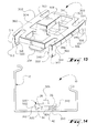
- FIG. 15 is a top perspective view of the line set duct system with the line set duct and a channel clip in accordance with a fourth embodiment of the present invention.
- FIG. 16 is a bottom perspective view of the channel clip in accordance with the fourth embodiment of the present invention.
- FIG. 17 is a top perspective view of the channel clip in accordance with the fourth embodiment of the present invention.
- FIG. 18 is an end elevation view of the line set duct system with the line set duct and the channel clip in accordance with the fourth embodiment of the present invention.
- a line set duct system 10 ( FIG. 3 ) of the present invention includes a line set duct 12 for housing a line set (not shown) of an HVAC system and a series of channel clips (a channel clip 100 — FIGS. 3-6 , a channel clip 200 — FIGS. 7-10 , a channel clip 300 — FIGS. 11-14 , and a channel clip 400 — FIGS. 15-18 ) for securing the line set within the line set duct 12 .
- the line set duct 12 includes a longitudinally extending duct base 14 with a longitudinally extending integral channel connector 26 , a longitudinally extending inside wall 16 , and a longitudinally extending outside wall 20 .
- the inside wall 16 has an inside wall top return 18
- the outside wall top return 20 has an outside wall top return 22 .
- the inside wall top return 18 and the outside wall top return 20 engage and secure a removable longitudinally extending cover (not shown) for the line set duct 12 .
- the channel connector 26 includes a first inverted L-shaped channel member 28 and a second inverted L-shaped channel member 36 attached to the duct base 14 , extending along the length of the duct base 14 , and extending parallel to each other.
- Each L-shaped channel member 28 and 36 has an inverted L-shaped cross-section with channel lips 30 and 38 and an channel webs 32 and 40 .
- the channel webs 32 and 40 are attached to the duct base 14 .
- the two inverted L-shaped channel members 28 and 36 are oriented to create two outwardly facing outside channel grooves 34 and 42 .
- the two outside channel grooves 34 and 42 are formed by the channel clips 30 and 38 , channel webs 32 and 40 , and the duct base 14 .
- a center channel groove 44 is created between the channel webs 32 and 34 of the inverted L-shaped channel members 28 and 36 .
- FIGS. 3-6 A first embodiment of the invention is shown in FIGS. 3-6 .
- the channel clip 100 has a generally planar and rectangular clip base 102 with a top 104 and a bottom 106 .
- Two legs, a first leg 112 and a second leg 122 are attached at one side of the clip base 102 and extend downwardly.
- the first leg 112 and the second leg 122 have downwardly extending portions 114 and 124 and perpendicularly extending portions 116 and 126 attached to the lower ends of the downwardly extending portions 114 and 124 , which together with the bottom 106 of the clip base 102 form a first leg groove 118 and a second leg groove 128 .
- the term “downwardly extending” refers to the direction toward the duct base 14 .
- the term “perpendicularly extending” refers to the direction that is essentially perpendicular to the downwardly extending portions of the legs and therefore essentially parallel to the clip base 102 .
- a third leg 132 is attached to an opposite side of the clip base 102 and extends downwardly.
- the third leg has a downwardly extending portion 134 and a perpendicularly extending portion 136 attached to the lower end of the downwardly extending portion 134 , which together with the bottom 106 of the clip base 102 form a third leg groove 138 .
- the perpendicularly extending portion 136 of the third leg 132 has a camming surface 140 distal from the bottom 106 of the clip base 102 .
- a tool opening 160 ( FIG. 5 ) in the clip base 102 allows a user to access the third leg 132 with a tool, such as a screwdriver, in order to release the perpendicularly extending portion 136 from the second channel lip 38 of the second L-shaped channel member 36 .
- the channel clip 100 has a clip collar 108 with a collar opening 110 attached to the top 104 of the clip base 102 for engaging a tie wrap or other fastener.
- the channel clip 100 also has a pair of friction elements, a first friction element 154 and second friction element 156 , extending downwardly from the center of the bottom 106 of the clip base 102 and dimensioned to fit within the width of the center channel groove 44 of the channel connector 26 .
- first leg groove 118 and the second leg groove 128 of the first leg 112 and the second leg 122 of the channel clip 100 first engage the channel lip 30 of the first L-shaped channel member 28 .
- the channel clip 100 is then pushed perpendicularly toward the duct base 14 so that the camming surface 140 of the third leg 132 rides over the channel lip 38 of the second L-shaped channel member 36 .
- the third leg groove 138 engages the channel lip 38 of the second L-shaped channel member 36 , and the channel clip 100 is thereby slidably attached to the line set channel connector 26 .
- the first and second friction elements 154 and 156 engage the duct base 14 of the center channel groove 44 to inhibit free sliding of the channel clip 100 along the line set channel connector 26 .
- the channel clip 100 can be removed from the line set channel connector 26 by engaging the perpendicularly extending portion 136 of the third leg 132 by means of a tool inserted through the tool opening 160 to releasing the perpendicularly extending portion 136 from the channel lip 38 of the second L-shaped channel member 36 .
- the channel clip 100 is removed by disengaging the first and second legs 112 and 122 from the channel clip 30 of the first L-shaped channel member 28 .
- FIGS. 7-10 A second embodiment of the invention is shown in FIGS. 7-10 .
- the channel clip 200 is similar to the channel clip 100 described above except for the addition of a release tab 258 .
- the channel clip 200 has a generally planar and rectangular clip base 202 with a top 204 and a bottom 206 .
- Two legs, a first leg 212 and a second leg 222 are attached at one side of the clip base 202 and extend downwardly.
- the first leg 212 and the second leg 222 have downwardly extending portions 214 and 224 and perpendicularly extending portions 216 and 226 attached to the lower ends of the downwardly extending portions 214 and 224 , which together with the bottom 206 of the clip base 202 form a first leg groove 218 and a second leg groove 228 .
- a third leg 232 is attached to an opposite side of the clip base 202 and extends downwardly.
- the third leg has a downwardly extending portion 234 and a perpendicularly extending portion 236 attached to the lower end of the downwardly extending portion 234 , which together with the bottom 206 of the clip base 202 form a third leg groove 238 .
- the perpendicularly extending portion 236 of the third leg 232 has a camming surface 240 distal from the bottom 206 of the clip base 202 .
- the channel clip 200 has a clip collar 208 with a collar opening 210 attached to the top 204 of the clip base 202 for engaging a tie wrap or other fastener.
- the channel clip 200 also has a pair of friction elements, a first friction element 254 and second friction element 256 , extending downwardly from the center of the bottom 206 of the clip base 202 and dimensioned to fit within the width of the center channel groove 44 of the channel connector 26 .
- the release tab 258 is attached to the top 204 of the clip base 202 and is an upward extension of the third leg 232 .
- the release tab 258 has a top end 262 and a bottom end 264 .
- the bottom end 264 of the release tab is attached to the top 204 of the clip base 202 directly above the third leg 232 .
- a tool opening 260 in the clip base 202 also allows a user to access the third leg 232 with a tool, such as a screwdriver, in order to release the perpendicularly extending portion 236 of the third leg 232 from the channel lip 38 of the second L-shaped channel member 36 .
- a tool such as a screwdriver
- FIGS. 11-14 A third embodiment of the invention is shown in FIGS. 11-14 .
- the channel clip 300 has a generally planar and rectangular clip base 302 with a top 304 and bottom 306 .
- the legs 312 , 322 , 332 , 342 have downwardly extending portions 314 , 324 , 334 , 344 and perpendicularly extending portions 316 , 326 , 336 , 346 attached to the lower end of the downwardly extending portions 314 , 324 , 334 , 344 , which together with the bottom 306 the clip base 302 form first, second, third, and fourth leg grooves 318 , 328 , 338 , and 348 , respectively.
- the perpendicularly extending portions 316 , 326 , 336 , 346 of the legs 312 , 322 , 332 , 342 have camming surfaces 320 , 330 , 340 , 350 distal from the clip base 302 .
- Tool openings 360 in the clip base 302 allows a user to access the four legs 312 , 322 , 332 , 342 with a tool, such as a screwdriver, in order to release the perpendicularly extending portions 316 , 326 , 336 , 346 of the four legs 312 , 322 , 332 , 342 from the channel lip 38 of the second L-shaped channel member 36 .
- the channel clip 300 has a clip collar 308 with a collar opening 310 attached to the top 304 of the clip base 302 for engaging a tie wrap or other fastener.
- the channel clip 300 also has a pair of friction elements, a first friction element 354 and second friction element 356 , extending downwardly from the center of the bottom 306 of the clip base 304 and dimensioned to fit within the width of the center channel groove 44 of the channel connector 26 .
- the channel clip 300 is pushed perpendicularly toward the duct base 14 so that the camming surfaces 320 , 330 , 340 , 350 of the four legs 312 , 322 , 332 , 342 ride over the channel lips 30 , 38 of the both L-shaped channel members 28 , 36 .
- the camming surfaces 320 , 330 , 340 , 350 have passed the channel lips 30 , 38 of the channel L-shaped members 28 , 36
- the leg grooves 318 , 328 , 338 , 348 engage the channel bases 30 , 38 of the L-shaped channel members 28 , 36
- the channel clip 300 is thereby slidably attached to the line set channel connector 26 .
- the first and second friction elements 354 and 356 engage the duct base 14 of the center channel groove 44 to inhibit free sliding of the channel clip 300 along the line set channel connector 26 .
- FIGS. 15-18 A fourth embodiment of the invention is shown in FIGS. 15-18 .
- the channel clip 400 has a generally planar and rectangular clip base 402 with a top 404 and bottom 406 .
- Two legs, a first leg 412 and a second leg 422 are attached at diagonal corners of the clip base 402 and extend downwardly.
- the first leg 412 and the second leg 422 have downwardly extending portions 414 , 424 and perpendicularly extending portions 416 , 426 attached to the lower end of the downwardly extending portions 414 , 424 , which together with the clip base 402 form a first leg groove 418 and a second leg groove 428 .
- the perpendicularly extending portions 416 , 426 of the legs 412 , 422 have camming surfaces 420 , 430 distal from the clip base 402 .
- the channel clip 400 also has downwardly extending stubs 432 , 442 at the corners of the clip base 402 diagonally opposite the legs 412 , 422 .
- Tool openings 460 in the clip base 402 allows a user to access the two legs 412 , 422 with a tool, such as a screwdriver, in order to release the perpendicularly extending portions 416 , 426 of the legs 412 , 422 from the channel lips 30 , 38 of the L-shaped channel members 28 , 36 .
- the channel clip 400 has a clip collar 408 with a collar opening 410 attached to the top 404 of the clip base 402 for engaging a tie wrap or other fastener.
- the channel clip 400 is pushed perpendicularly toward the duct base 14 so that the camming surfaces 420 , 430 of the two legs 412 , 422 ride over the channel bases 30 , 38 of the both L-shaped channel members 28 , 36 .
- the leg grooves 418 , 428 engage the channel lips 30 , 38 of the L-shaped channel members 28 , 36 , and the channel clip 400 is thereby slidably attached to the line set channel connector 26 .
- the stubs 432 , 442 engage the L-shaped channel members 28 , 36 to keep the channel clip 400 from rotating around an axis perpendicular to the duct base 14 .
Landscapes
- Engineering & Computer Science (AREA)
- General Engineering & Computer Science (AREA)
- Mechanical Engineering (AREA)
- Chemical & Material Sciences (AREA)
- Combustion & Propulsion (AREA)
- Clamps And Clips (AREA)
Abstract
Description
Claims (10)
Priority Applications (1)
| Application Number | Priority Date | Filing Date | Title |
|---|---|---|---|
| US14/933,541 US9528635B2 (en) | 2015-02-17 | 2015-11-05 | Line set duct with channel clip |
Applications Claiming Priority (2)
| Application Number | Priority Date | Filing Date | Title |
|---|---|---|---|
| US201562117067P | 2015-02-17 | 2015-02-17 | |
| US14/933,541 US9528635B2 (en) | 2015-02-17 | 2015-11-05 | Line set duct with channel clip |
Publications (2)
| Publication Number | Publication Date |
|---|---|
| US20160238163A1 US20160238163A1 (en) | 2016-08-18 |
| US9528635B2 true US9528635B2 (en) | 2016-12-27 |
Family
ID=56620966
Family Applications (1)
| Application Number | Title | Priority Date | Filing Date |
|---|---|---|---|
| US14/933,541 Expired - Fee Related US9528635B2 (en) | 2015-02-17 | 2015-11-05 | Line set duct with channel clip |
Country Status (1)
| Country | Link |
|---|---|
| US (1) | US9528635B2 (en) |
Cited By (2)
| Publication number | Priority date | Publication date | Assignee | Title |
|---|---|---|---|---|
| US10451198B2 (en) * | 2017-06-19 | 2019-10-22 | Thomas & Betts International Llc | Cable tray hold-down clamp |
| US20240052861A1 (en) * | 2022-08-10 | 2024-02-15 | Ff Away, Llc | Clip apparatus |
Families Citing this family (2)
| Publication number | Priority date | Publication date | Assignee | Title |
|---|---|---|---|---|
| US12487006B2 (en) * | 2015-03-25 | 2025-12-02 | Sterling Custom Sheet Metal, Inc. | Insulated register box assembly having radius clip disc |
| CN107881860A (en) * | 2017-11-27 | 2018-04-06 | 苏州惠琪特电子科技有限公司 | A kind of metal plate clamping track |
Citations (2)
| Publication number | Priority date | Publication date | Assignee | Title |
|---|---|---|---|---|
| US5639048A (en) * | 1995-01-19 | 1997-06-17 | Thomas & Betts Corporation | Cable tray system |
| US5730398A (en) * | 1995-06-22 | 1998-03-24 | Mirai Industries Co., Ltd. | Cable bed and traveler rung used therein |
-
2015
- 2015-11-05 US US14/933,541 patent/US9528635B2/en not_active Expired - Fee Related
Patent Citations (2)
| Publication number | Priority date | Publication date | Assignee | Title |
|---|---|---|---|---|
| US5639048A (en) * | 1995-01-19 | 1997-06-17 | Thomas & Betts Corporation | Cable tray system |
| US5730398A (en) * | 1995-06-22 | 1998-03-24 | Mirai Industries Co., Ltd. | Cable bed and traveler rung used therein |
Cited By (2)
| Publication number | Priority date | Publication date | Assignee | Title |
|---|---|---|---|---|
| US10451198B2 (en) * | 2017-06-19 | 2019-10-22 | Thomas & Betts International Llc | Cable tray hold-down clamp |
| US20240052861A1 (en) * | 2022-08-10 | 2024-02-15 | Ff Away, Llc | Clip apparatus |
Also Published As
| Publication number | Publication date |
|---|---|
| US20160238163A1 (en) | 2016-08-18 |
Similar Documents
| Publication | Publication Date | Title |
|---|---|---|
| US9528635B2 (en) | Line set duct with channel clip | |
| US8079561B2 (en) | Universal metal stud clip | |
| US8573881B2 (en) | Device for securing an add-on to a support | |
| CA2999660C (en) | Stacked plate heat exchanger with form fitting connection of the plates | |
| RU2487285C1 (en) | Coupling element | |
| CA2898911C (en) | Clip for perimeter trim | |
| US4943022A (en) | Bracket for mounting an electrical box on a wall stud | |
| US20110214713A1 (en) | Solar battery module | |
| US20160138633A1 (en) | Fitting for strut channel | |
| US20110314641A1 (en) | Cable binding device | |
| TW201248022A (en) | Mounting apparatus for fan | |
| AU2017202250B2 (en) | Building connection apparatus | |
| US9435071B2 (en) | Leg retaining clip | |
| JP2020510167A (en) | Mounting device and related method | |
| US20090165999A1 (en) | Heat sink | |
| FI20136084A7 (en) | Arrangement for attaching panels to support structures, a construction support structure and fastening means, and their use in modular building elements | |
| TWM621355U (en) | Heat dissipation module | |
| JP2021061715A5 (en) | ||
| JP5917189B2 (en) | Ventilator | |
| US20170082127A1 (en) | Security display unit | |
| CN104891050A (en) | Refrigerator packaging structure and refrigerator packaging box | |
| KR100797767B1 (en) | Air Doc | |
| GB571607A (en) | Improvements in or relating to fastening or securing devices | |
| JPH0755376Y2 (en) | Hook tack | |
| CN208122124U (en) | A kind of magnetic coupling roof structure and building |
Legal Events
| Date | Code | Title | Description |
|---|---|---|---|
| AS | Assignment |
Owner name: DIVERSITECH CORPORATION, GEORGIA Free format text: ASSIGNMENT OF ASSIGNORS INTEREST;ASSIGNORS:LOWE, BRYCE;JONES, EMANUEL;SADA, JONATHAN;REEL/FRAME:040279/0302 Effective date: 20161107 |
|
| STCF | Information on status: patent grant |
Free format text: PATENTED CASE |
|
| AS | Assignment |
Owner name: ROYAL BANK OF CANADA, AS SECOND LIEN COLLATERAL AGENT AND ASSIGNEE, CANADA Free format text: SECURITY INTEREST;ASSIGNOR:DIVERSITECH CORPORATION;REEL/FRAME:042648/0397 Effective date: 20170601 Owner name: ROYAL BANK OF CANADA, AS FIRST LIEN COLLATERAL AGENT AND ASSIGNEE, CANADA Free format text: SECURITY INTEREST;ASSIGNOR:DIVERSITECH CORPORATION;REEL/FRAME:042647/0864 Effective date: 20170601 Owner name: ROYAL BANK OF CANADA, AS FIRST LIEN COLLATERAL AGE Free format text: SECURITY INTEREST;ASSIGNOR:DIVERSITECH CORPORATION;REEL/FRAME:042647/0864 Effective date: 20170601 Owner name: ROYAL BANK OF CANADA, AS SECOND LIEN COLLATERAL AG Free format text: SECURITY INTEREST;ASSIGNOR:DIVERSITECH CORPORATION;REEL/FRAME:042648/0397 Effective date: 20170601 |
|
| MAFP | Maintenance fee payment |
Free format text: PAYMENT OF MAINTENANCE FEE, 4TH YR, SMALL ENTITY (ORIGINAL EVENT CODE: M2551); ENTITY STATUS OF PATENT OWNER: SMALL ENTITY Year of fee payment: 4 |
|
| MAFP | Maintenance fee payment |
Free format text: PAYMENT OF MAINTENANCE FEE UNDER 1.28(C) (ORIGINAL EVENT CODE: M1559); ENTITY STATUS OF PATENT OWNER: LARGE ENTITY |
|
| FEPP | Fee payment procedure |
Free format text: ENTITY STATUS SET TO UNDISCOUNTED (ORIGINAL EVENT CODE: BIG.); ENTITY STATUS OF PATENT OWNER: LARGE ENTITY |
|
| FEPP | Fee payment procedure |
Free format text: PETITION RELATED TO MAINTENANCE FEES GRANTED (ORIGINAL EVENT CODE: PTGR); ENTITY STATUS OF PATENT OWNER: LARGE ENTITY |
|
| AS | Assignment |
Owner name: TRIATOMIC ENVIRONMENTAL, INC., FLORIDA Free format text: RELEASE BY SECURED PARTY;ASSIGNOR:ROYAL BANK OF CANADA;REEL/FRAME:058575/0909 Effective date: 20211222 Owner name: DIVERSITECH CORPORATION, GEORGIA Free format text: RELEASE BY SECURED PARTY;ASSIGNOR:ROYAL BANK OF CANADA;REEL/FRAME:058575/0909 Effective date: 20211222 Owner name: DIVERSITECH CORPORATION, GEORGIA Free format text: RELEASE OF SECURITY INTEREST;ASSIGNOR:ROYAL BANK OF CANADA;REEL/FRAME:058575/0909 Effective date: 20211222 Owner name: TRIATOMIC ENVIRONMENTAL, INC., FLORIDA Free format text: RELEASE OF SECURITY INTEREST;ASSIGNOR:ROYAL BANK OF CANADA;REEL/FRAME:058575/0909 Effective date: 20211222 |
|
| AS | Assignment |
Owner name: ROYAL BANK OF CANADA AS COLLATERAL AGENT, CANADA Free format text: FIRST LIEN PATENT SECURITY AGREEMENT;ASSIGNORS:DIVERSITECH CORPORATION;TRIATOMIC ENVIRONMENTAL, INC.;STRIDE TOOL, LLC;AND OTHERS;REEL/FRAME:058576/0051 Effective date: 20211222 Owner name: ROYAL BANK OF CANADA AS COLLATERAL AGENT, CANADA Free format text: SECOND LIEN PATENT SECURITY AGREEMENT;ASSIGNORS:DIVERSITECH CORPORATION;TRIATOMIC ENVIRONMENTAL, INC.;STRIDE TOOL, LLC;AND OTHERS;REEL/FRAME:058528/0954 Effective date: 20211222 |
|
| FEPP | Fee payment procedure |
Free format text: MAINTENANCE FEE REMINDER MAILED (ORIGINAL EVENT CODE: REM.); ENTITY STATUS OF PATENT OWNER: LARGE ENTITY |
|
| LAPS | Lapse for failure to pay maintenance fees |
Free format text: PATENT EXPIRED FOR FAILURE TO PAY MAINTENANCE FEES (ORIGINAL EVENT CODE: EXP.); ENTITY STATUS OF PATENT OWNER: LARGE ENTITY |
|
| STCH | Information on status: patent discontinuation |
Free format text: PATENT EXPIRED DUE TO NONPAYMENT OF MAINTENANCE FEES UNDER 37 CFR 1.362 |
|
| FP | Lapsed due to failure to pay maintenance fee |
Effective date: 20241227 |