US9524829B2 - Solid electrolytic capacitor and improved method for manufacturing a solid electrolytic capacitor - Google Patents
Solid electrolytic capacitor and improved method for manufacturing a solid electrolytic capacitor Download PDFInfo
- Publication number
- US9524829B2 US9524829B2 US14/595,502 US201514595502A US9524829B2 US 9524829 B2 US9524829 B2 US 9524829B2 US 201514595502 A US201514595502 A US 201514595502A US 9524829 B2 US9524829 B2 US 9524829B2
- Authority
- US
- United States
- Prior art keywords
- capacitor
- forming
- layer
- conducting polymer
- liquid
- Prior art date
- Legal status (The legal status is an assumption and is not a legal conclusion. Google has not performed a legal analysis and makes no representation as to the accuracy of the status listed.)
- Active, expires
Links
Images


Classifications
-
- H—ELECTRICITY
- H01—ELECTRIC ELEMENTS
- H01G—CAPACITORS; CAPACITORS, RECTIFIERS, DETECTORS, SWITCHING DEVICES OR LIGHT-SENSITIVE DEVICES, OF THE ELECTROLYTIC TYPE
- H01G9/00—Electrolytic capacitors, rectifiers, detectors, switching devices, light-sensitive or temperature-sensitive devices; Processes of their manufacture
- H01G9/0029—Processes of manufacture
- H01G9/0032—Processes of manufacture formation of the dielectric layer
-
- H—ELECTRICITY
- H01—ELECTRIC ELEMENTS
- H01G—CAPACITORS; CAPACITORS, RECTIFIERS, DETECTORS, SWITCHING DEVICES OR LIGHT-SENSITIVE DEVICES, OF THE ELECTROLYTIC TYPE
- H01G9/00—Electrolytic capacitors, rectifiers, detectors, switching devices, light-sensitive or temperature-sensitive devices; Processes of their manufacture
- H01G9/0029—Processes of manufacture
- H01G9/0036—Formation of the solid electrolyte layer
-
- H—ELECTRICITY
- H01—ELECTRIC ELEMENTS
- H01G—CAPACITORS; CAPACITORS, RECTIFIERS, DETECTORS, SWITCHING DEVICES OR LIGHT-SENSITIVE DEVICES, OF THE ELECTROLYTIC TYPE
- H01G9/00—Electrolytic capacitors, rectifiers, detectors, switching devices, light-sensitive or temperature-sensitive devices; Processes of their manufacture
- H01G9/004—Details
- H01G9/008—Terminals
- H01G9/012—Terminals specially adapted for solid capacitors
-
- H—ELECTRICITY
- H01—ELECTRIC ELEMENTS
- H01G—CAPACITORS; CAPACITORS, RECTIFIERS, DETECTORS, SWITCHING DEVICES OR LIGHT-SENSITIVE DEVICES, OF THE ELECTROLYTIC TYPE
- H01G9/00—Electrolytic capacitors, rectifiers, detectors, switching devices, light-sensitive or temperature-sensitive devices; Processes of their manufacture
- H01G9/004—Details
- H01G9/022—Electrolytes; Absorbents
- H01G9/025—Solid electrolytes
- H01G9/028—Organic semiconducting electrolytes, e.g. TCNQ
-
- H—ELECTRICITY
- H01—ELECTRIC ELEMENTS
- H01G—CAPACITORS; CAPACITORS, RECTIFIERS, DETECTORS, SWITCHING DEVICES OR LIGHT-SENSITIVE DEVICES, OF THE ELECTROLYTIC TYPE
- H01G9/00—Electrolytic capacitors, rectifiers, detectors, switching devices, light-sensitive or temperature-sensitive devices; Processes of their manufacture
- H01G9/15—Solid electrolytic capacitors
-
- Y10T29/417—
Definitions
- the present invention is related to an improved solid electrolytic capacitor and an improved method of manufacturing a solid electrolytic capacitor. More specifically, the present invention is related to an improved treatment method which provides for improvements in the coating quality and physical properties of the finished capacitor.
- Solid electrolytic capacitors have been widely used for many years throughout the industry. Of particular interest herein is a solid electrolytic capacitor comprising a cathode of an intrinsically conducting polymer such as polyaniline, polythiophene or polypyrroles.
- the polymers are usually either formed in-situ or by dipping into a slurry of polymer. With in-situ formation a capacitor precursor is introduced into a monomer solution wherein the monomer is polymerized either electrochemically or by chemical means.
- each slurry layer tends to dry and form a skin. Subsequent layers then do not adequately migrate through the skin into previous layers and the layers are joined by adhesion not cohesion. The result is the formation of a cathode wherein discrete layers separate, or delaminate, under harsh conditions thereby decreasing conductivity between adjacent layers and increasing equivalent series resistance (ESR).
- ESR equivalent series resistance
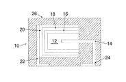
- FIG. 1 is a cross-sectional schematic view of an embodiment of the invention.
- FIG. 2 is a cross-sectional schematic partially-exploded view of an embodiment of the invention.
- FIG. 3 is a flow chart representation of an embodiment of the invention.
- FIG. 4 is a cross-sectional view of a cathode layer without inventive treatment.
- FIG. 5 is a cross-sectional view of a cathode layer with inventive treatment.
- the present invention is directed to an improved capacitor and improved method of making a capacitor, particularly a solid electrolytic capacitor comprising intrinsically conductive polymer, with improved stability under adverse and processing conditions. More specifically, the present invention provides a method of fusing conductive polymer layers by using high temperature and high humidity treatment, by soaking the layered structure in a liquid or solution, or by vapor treatment with some selected liquid that helps to swell and fuse the distinctive layers. This improves the bonding between adjacent layers of intrinsically conductive polymer
- a capacitor generally represented at 10 , comprises an anode, 12 , with an anode wire, 14 , extending therefrom.
- a dielectric, 16 is on the anode at least partially encasing the anode.
- a conductive polymeric cathode, 18 is on the dielectric and separated from the anode by the dielectric.
- Adhesion layers, 20 provide a layer which allows adhesion to a cathode external termination, 22 .
- An anode external termination, 24 is in electrical contact with the anode wire.
- the entire capacitor, except for the lower portion of the anode and cathode external terminations, is preferably encased in a non-conductive matrix, 26 , or sealed in a hermetically sealed container as known in the art.
- FIG. 2 An embodiment of the invention is illustrated in FIG. 2 wherein a capacitor is generally represented at 110 .
- a series of anodes, 120 are arranged in parallel fashion. Each anode has a dielectric, 116 , thereon.
- a conductive polymer cathode, 118 is on each dielectric. The anodes are fused at 123 and the cathodes are commonly terminated.
- the present invention provides a method for fusing conductive polymer layers by using high temperature and high humidity treatment, by soaking the layered structure in a liquid or solution, or by vapor treatment with some selected liquid that helps to swell and fuse the distinctive layers. This improves the bonding between adjacent layers of intrinsically conductive polymer and results in improved ESR and ESR stability.
- FIG. 3 An embodiment of the invention is illustrated in flow-chart form in FIG. 3 .
- an anode is provided at 30 .
- a dielectric is formed on the anode at 32 .
- An initial coating of primer is applied at 34 followed by coating with a conductive polymer, preferably as a slurry, at 36 .
- Subsequent layers are applied at 38 .
- At least two polymer coatings are applied with the number based on the desired thickness and completeness of coverage.
- a particularly preferred conductive polymer is poly 3,4-ethylenedioxythiophene (PEDT).
- PEDT slurry is commercially available from Heraeus as Clevios® KV2.
- the layers are dried and then fused at 40 , preferably, at a temperature of at least 50° C.
- the capacitor is finished at 42 by forming anodic and cathode external terminations and optionally encapsulating or sealing the capacitor.
- the layered structure can be treated with a liquid, preferably a polar liquid, which enhances the swelling.
- a liquid for swelling the layered structure includes water, ethylene glycol, propylene glycol, glycerol, dimethyl sulfoxide (DMSO), N-methyl pyrrolidone or N, N-dimethylformamide (DMF).
- Treatment is preferably done by dipping due to the manufacturing efficiency provided thereby with other techniques, such as spraying, suitable for demonstration of the invention.
- the liquid is removed by either reduced pressure, increased temperature or some combination thereof at a rate sufficient to avoid surface drying or skinning.
- the temperature is preferably no more than the boiling point of the liquid even though this temperature can be exceeded if surface drying is not caused by the more rapid liquid removal. Temperatures of 25° C. to 150° C. are suitable for demonstration of the invention with glycerol.
- the layered structure can be treated with an aqueous or nonaqueous solution of a chemical that can help to swell the layered structure.
- a chemical that can help to swell the layered structure.
- Particularly preferred solvents include water; alcohol such as ethanol or isopropanol; ketones such as acetone or methyl ethyl ketone; ethers; esters such as ethyl acetate or isoamyl acetate or ring based polar solvents such as tetrahydrofurane (THF).
- Suitable solutes include any compound that helps to swell the layered structure.
- particularly preferred solutes also include polar solid compounds such as polyols including sorbitol, mannitol, sucrose and lactose and amino acids including glycine, alanine and lysine.
- Treatment is preferably done by dipping due to the manufacturing efficiency provided thereby with other techniques, such as spraying, suitable for demonstration of the invention.
- After sufficient treatment to achieve swelling the parts are dried to at least partially remove the solvent by either reduced pressure, increased temperature or some combination thereof at a rate sufficient to avoid surface drying or skinning.
- the temperature is preferably no more than the boiling point of the liquid even though this temperature can be exceeded if surface drying is not caused by the more rapid liquid removal. Temperatures of 25° C. to 150° C. are suitable for demonstration of the invention with aqueous solution.
- layered structure can be treated with vapor of any liquid or solute mentioned in the above embodiment.
- Heat can be optionally applied to speed up the swelling and fusing of conductive polymer layers.
- the primer preferably comprises a cross-linker and a weak ionic acid counter-ion.
- the weak ionic acid counterion preferably comprising multiple carboxylic acid groups and has a preferred pKa of at least 0.25 to no more than about 6. More preferably the weak ionic acid counterion has a pKa of at least 2.15 to no more than about 6. Below a pKa of about 0.25 the finished part fails in accelerated reliability test. Above a pKa of about 6 the ionic acid is insufficiently ionic to function as a suitable counterion. Acids containing multiple carboxyl groups on a linear or branched hydrocarbon of at least one to 20 carbons, are particularly preferred. Above about 20 carbons the solubility of the weak ionic acid counterion becomes limiting.
- a particularly preferred weak ionic acid counterion is selected from the group consisting of acetic acid, 1,2,3,4-butanetetracarboxylic acid, lysine and butanetetraacetic acid
- Typical primers, particularly, and cross-linkers are known to be detrimentally impacted by moisture due, presumably, to their ionic nature.
- Aluminum is particularly known to be detrimentally impacted by the presence of moisture. It has therefore been considered necessary to avoid high moisture conditions during the manufacture of capacitors utilizing intrinsically conducting polymer due to the presence of the primers specifically.
- the use of relatively high moisture and heat as set forth elsewhere herein, fuses adjacent layers of the intrinsically conductive polymer thereby achieving superior properties, particularly ESR, of the resultant capacitor. This result is contrary to the expectation of those of skill in the art.
- moist heat improves inter-layer bonding within the layers of intrinsically conducting polymer allows for the use of previously unsuitable weak counter ions thereby greatly improving the reliability characteristics of the capacitor. The result is a capacitor with improved stability upon aging and subsequent use.
- the cross-linker is preferably a diamine, triamine, oligoamine or derivatives thereof wherein oligoamine refers to compounds comprising at least four amine groups such as tetramine, pentamine, hexamine, heptamine, octamine, nonamine, decamine, undecamine, dodecamine, etc.
- Particularly preferred amines are selected from aliphatic amines, amides, aromatic amines, amino acids, polymeric amines, and polyether amines.
- Aliphatic amines including ⁇ , ⁇ -diamines such as 1,4-diaminocyclohexane or 1,4-bis aminomethyl(cyclohexane), or
- linear aliphatic ⁇ , ⁇ -diamines or derivatives thereof such as ethylenediamine, 1,6-hexanediamine, 1,7-heptanediamine, 1,8-octanediamine, 1,9-nonanediamine, 1,10-decanediamine or 1,12-dodecanediamine N,N-dimethylethylenediamine, N,N,N′N′tetramethyl-1,4,butanediamine, N,N,N,N′N′N;-hexamethylhexanemethylene-diammonium dibromide, piperazine, 1,4-diazabicyclo[2.2.2]octane, N,N,N′N-tetrakis(2-hydroxypropyl)ethylenediamine, N-[3-(trimethoxysilyl)propyl]ethylenediamine or 1,4-bis(3-amino-propyl)piperazine; amides such as N,N′-diacetyl-1,6
- Solid electrolytic capacitors generally comprise a porous metal anode, an oxide layer on the anode, typically an oxide of the anode metal, and an electrically conductive solid cathode, such as manganese dioxide or an intrinsically conductive polymer, incorporated into the pores and onto the dielectric.
- the porous structure gives high surface area. An advantage of the high surface area is that a very high capacitance can be achieved. Additional layers, such as silver and carbon layers, are then added to aid in contact formation.
- the solid electrolytic capacitors typically incorporate valve metals or conductive oxides of valve metals with tantalum, aluminum, niobium and niobium oxide being mentioned as particularly preferred.
- the dielectric is typically formed as an oxide of the anode metal without limit thereto. Dielectric formation is well documented in the art and the method of dielectric formation is not limited herein.
- Conductive polymers are particularly suitable for use as the electrically conductive solid cathode with polyaniline, polypyrroles and polythiophenes being most preferred.
- a particularly preferred polymer for use as a cathode is polythiophene.
- the polymer layer inside the pores can be formed by chemical polymerization wherein the internal conductive layer is formed by dipping the anodized substrate first in a solution of monomer of the conductive polymer. After a drying step, the anode bodies are then immersed in a solution comprising oxidizer and dopant. The chemical polymerization cycle can be repeated multiple times to achieve the desired coverage of the surface inside the pores.
- the polymer layer inside the pores can also be formed by dip coating using a solution or dispersion of conductive polymer.
- a diluted solution is preferred so that the solution viscosity would be sufficiently low to allow diffusion of the solution into the porous structure.
- the particle size must be sufficiently small to allow impregnation of the porous structure.
- a layer of conductive polymer can be applied with a slurry or dispersion of the conductive polymer. It is preferred to include a dopant in the polymer as known in the art.
- a particularly preferred dopant is the sodium salt of polystyrenesulfonate (PSS) or polestersulfonate (PES).
- the conducting polymer is preferably an intrinsically conducting polymer comprising repeating units of a monomer of Formula I:
- R 1 and R 2 of Formula I are preferably chosen to prohibit polymerization at the ⁇ -site of the ring. It is most preferred that only ⁇ -site polymerization be allowed to proceed. Therefore, it is preferred that R 1 and R 2 are not hydrogen. More preferably R 1 and R 2 are ⁇ -directors. Therefore, ether linkages are preferable over alkyl linkages. It is most preferred that the groups are small to avoid steric interferences. For these reasons R 1 and R 2 taken together as —O—(CH 2 ) 2 —O— is most preferred.
- X is S, Se or N. Most preferably X is S.
- R 1 and R 2 independently represent linear or branched C 1 -C 16 alkyl or C 1 -C 18 alkoxyalkyl; or are C 3 -C 8 cycloalkyl, phenyl or benzyl which are unsubstituted or substituted by C 1 -C 6 alkyl, C 1 -C 6 alkoxy, halogen or OR 3 ; or R 1 and R 2 taken together, are linear C 1 -C 6 alkylene which is unsubstituted or substituted by C 1 -C 6 alkyl, C 1 -C 6 alkoxy, halogen, C 3 -C 8 cycloalkyl, phenyl, benzyl, C 1 -C 4 alkylphenyl, alkoxyphenyl, halophenyl, C 1 -C 4 alkylbenzyl, C 1 -C 4 alkoxybenzyl or halobenzyl, 5-, 6-, or 7-membered heterocyclic structure containing
- R 3 preferably represents hydrogen, linear or branched C 1 -C 16 alkyl or C 1 -C 18 alkoxyalkyl; or are C 3 -C 8 cycloalkyl, phenyl or benzyl which are unsubstituted or substituted by C 1 -C 6 alkyl.
- R 1 and R 2 independently represent —CH 3 , —CH 2 CH 3 ; —OCH 3 ; —OCH 2 CH 3 or most preferably R 1 and R 2 are taken together to represent —OCH 2 CH 2 O— wherein the hydrogen can be replaced with a solubilizing group, a halide or an alkyl.
- a solvent is defined as a single solvent or a mixture of solvents.
- the dispersion comprising the conductive polymer at a pH of no more than 10 and more preferably no more than 8 with below 7 being more preferred and below 6 being especially preferred.
- the conductive polymer dispersion is applied onto the primer to form a layer that covers the edges and corners of the anodes.
- the application of primer layer and the conductive polymer layer can be repeated multiple times to achieve enough thickness and completeness of coverage. Without limit thereto 2-10 cycles of primer and conductive polymer layer application are suitable for demonstration of the invention.
- Each application of conductive polymer may use a unique composition and a unique solution or an identical or similar material may be used for the various dipping steps.
- a preferred thickness of the conductive polymer layer is at least 2 micrometers to no more than 50 micrometers.
- a more preferred thickness of the conductive polymer layer is from at least 2 micrometers to no more than 40 micrometers.
- An even more preferred thickness is from at least 3 micrometers to no more than 30 micrometers. If the layer of conductive polymer is below about 2 micrometers the dielectric is not adequately covered resulting in defective capacitors. If the conductive polymer layer is over about 50 micrometers the equivalent series resistance of the resulting capacitor is
- Nanoparticle dispersion is applied after formation of the initial conductive polymer layer and after formation of subsequent conductive polymer layers.
- the sequence of applying the nanoparticle dispersion material followed by applying a conductive polymer layer is repeated until the desired layer thickness is reached. Without limit thereto 2-10 cycles of the nanoparticle dispersion and conductive polymer layer application is suitable for demonstration of the invention.
- Nanoparticle dispersions comprise nanoparticles with the nanoparticles having a particle size of no more than 100 nm and more preferably no more than 50 nm.
- Nanoparticles of the nanoparticle dispersion are selected from aluminum oxide, zinc oxide, silicon oxide and cerium oxide. These nanoparticle dispersions are available from Byk Additives And Instruments under commercial name Nanobyk 3600 for aluminum oxide, Nanobyk 3810 for cerium oxide and Nanobyk 3820 for zinc oxide.
- HAST is Highly Accelerated Stress Test wherein a sample can be tested for corrosion resistance under electrical bias at 121° C. and 85% RH. HAST testing typically requires about 1-200 hours.
- b-HAST refers to a test under electrical bias and ub-HAST is the same test without electrical bias.
- FIG. 4 illustrates a cross-sectional view of the intrinsically conducting polymeric cathode layer, coated using conventional Clevious® K Primer W, in a solid electrolytic capacitor treated by conventional drying techniques. Inter-layer striations are easily observed which are believed to separate upon aging.
- FIG. 5 illustrates an identically prepared layer treated at 121° C. in 85% relative humidity wherein the striation is not observed and the intrinsically conductive polymer layer appears to be a continuous layer which does not as easily delaminate upon aging.
- Moist heat especially with aluminum, has long been considered detrimental due to anode degradation. It is surprisingly found that with weak ionic counterions moist heat can be used, preferably with a post heating step, to provide an improved capacitor exhibiting relatively low ESR, good stability during manufacturing process and low leakage current with aluminum anodes as well as improved reliability. The anode does not suffer from corrosion as is commonly realized with prior art strong acid counterions. In yet another surprising result, when the inventive capacitor is subsequently dried, the ESR and leakage current remain low during subsequent processing.
- a series of capacitors were formed on an aluminum anode with aluminum oxide dielectric.
- the dielectric was coated with a commercially available primer comprising dodecane diamine and toluene sulphonic acid available as Clevios® K Primer W from Heraeus.
- a layer of intrinsically conducting 3,4-ethylenedioxythiophene polymer available as Clevios® KV2 from Heraeus was formed on the dried primer.
- the capacitor was tested for ESR, the ratio of edge to body coating thickness and b-HAST. The results are presented in Table 1 as Comparative 1.
- a series of capacitors were formed on an aluminum anode with aluminum oxide dielectric.
- the dielectric was coated with a primer comprising dodecane diamine and 1,2,3,4-butanetetracarboxylic acid in a 1:1 molar ratio.
- Sequential layers of intrinsically conducting 3,4-ethylenedioxythiophene polymer available as Clevios® KV2 from Heraeus were formed on the dried primer.
- the capacitor was tested for ESR, the ratio of edge to body coating thickness and b-HAST. The results are presented in Table 1 as Inventive 1.
- inventive 1 has superior thickness uniformity with a near equal thickness at the edges and the body.
- inventive example 1 also has superior results in accelerated reliability test.
- the inventive example 1 suffers from an increase in ESR.
- a series of capacitors from Comparative 1 and Inventive 1 were separated and subjected to 260° C. infrared heat treatment and to an oven heat treatment at 125° C., 150° C., and 175° C. for 2 hours. Under infrared heating conditions both samples demonstrated a slight increase in ESR. No obvious insulation layer was observed in cross-sectional views. A series of capacitors was also heated at 85° C. and 85% humidity at rated voltage and without voltage. ESR did not decrease.
- a series of capacitors from Comparative 1 and Inventive 1 were separated and subjected to treatment at 121° C. and 85% relative humidity at rated voltage and under identical conditions without voltage.
- Inventive 1 demonstrated a significant decrease in ESR from a mean of about 0.050 Ohms to a mean of about 0.020 Ohms which is comparable to Comparative 1 without the treatment.
- leakage current after the treatment both with and without voltage, was stable and acceptable.
- a series of capacitors from Comparative 1 and Inventive 1 were prepared, with the exception that two layers of intrinsically conductive polymer were applied sequentially. The samples were separated and subjected to moist treatment at 121° C. and 85% relative humidity at rated voltage and under identical conditions without voltage. Inventive 1 demonstrated a significant decrease in ESR from a mean of about 0.050 Ohms to a mean of about 0.020 Ohms which is comparable to Comparative 1 without moist treatment. In further processing the ESR remained stable post molding. The finished capacitors with encapsulation were tested for 21 hours under HAST condition. Leakage current was stable and acceptable. In contrast, capacitors made from Comparative 1 showed severe increase in leakage current.
- a series of capacitors from Comparative 1 and Inventive 1 were separated and subjected to treatment by dipping in glycerol for 5 mins followed by drying at 130° C. for 30 mins.
- Inventive 1 demonstrated a significant decrease in ESR from a mean of about 0.050 Ohms to a mean of about 0.026 Ohms which is comparable to Comparative 1 without the treatment.
Abstract
- providing an anode comprising a dielectric thereon;
- applying a first layer of an intrinsically conducting polymer on the dielectric to form a capacitor precursor;
- applying at least one subsequent layer of an intrinsically conducting polymer on the first layer from a dispersion; and
- treating the capacitor precursor at a temperature of at least 50° C. no more than 200° C. at a relative humidity of at least 25% up to 100%,
- or fusing the layered structure by swelling the layered structure with a liquid and at least partially removing the liquid.
Description


R1 and R2 of Formula I are preferably chosen to prohibit polymerization at the β-site of the ring. It is most preferred that only α-site polymerization be allowed to proceed. Therefore, it is preferred that R1 and R2 are not hydrogen. More preferably R1 and R2 are α-directors. Therefore, ether linkages are preferable over alkyl linkages. It is most preferred that the groups are small to avoid steric interferences. For these reasons R1 and R2 taken together as —O—(CH2)2—O— is most preferred.
| TABLE 1 | |||
| Sample | Solid ESR (Ohms) | Edge/Body ratio | b-HAST |
| Comparative 1 | 0.025 | 0.7 | fail |
| Inventive 1 | 0.050 | 0.9 | pass |
| TABLE 2 | ||||||
| Post | End | 5 Pass | Post | |||
| Sample | molding | of line | Reflow | b-HAST | ||
| Comparative 1 | 0.014 | 0.023 | 0.036 | 0.143 | ||
| Inventive 1 | 0.011 | 0.014 | 0.016 | 0.022 | ||
Claims (34)
Priority Applications (2)
| Application Number | Priority Date | Filing Date | Title |
|---|---|---|---|
| US14/595,502 US9524829B2 (en) | 2013-05-17 | 2015-01-13 | Solid electrolytic capacitor and improved method for manufacturing a solid electrolytic capacitor |
| US15/083,381 US9761347B2 (en) | 2013-05-17 | 2016-03-29 | Process to improve coverage and electrical performance of solid electrolytic capacitor |
Applications Claiming Priority (2)
| Application Number | Priority Date | Filing Date | Title |
|---|---|---|---|
| US13/896,672 US9343239B2 (en) | 2013-05-17 | 2013-05-17 | Solid electrolytic capacitor and improved method for manufacturing a solid electrolytic capacitor |
| US14/595,502 US9524829B2 (en) | 2013-05-17 | 2015-01-13 | Solid electrolytic capacitor and improved method for manufacturing a solid electrolytic capacitor |
Related Parent Applications (2)
| Application Number | Title | Priority Date | Filing Date |
|---|---|---|---|
| US13/896,672 Division US9343239B2 (en) | 2013-05-17 | 2013-05-17 | Solid electrolytic capacitor and improved method for manufacturing a solid electrolytic capacitor |
| US15/083,381 Division US9761347B2 (en) | 2013-05-17 | 2016-03-29 | Process to improve coverage and electrical performance of solid electrolytic capacitor |
Related Child Applications (1)
| Application Number | Title | Priority Date | Filing Date |
|---|---|---|---|
| US15/083,381 Continuation-In-Part US9761347B2 (en) | 2013-05-17 | 2016-03-29 | Process to improve coverage and electrical performance of solid electrolytic capacitor |
Publications (2)
| Publication Number | Publication Date |
|---|---|
| US20150124374A1 US20150124374A1 (en) | 2015-05-07 |
| US9524829B2 true US9524829B2 (en) | 2016-12-20 |
Family
ID=51895603
Family Applications (2)
| Application Number | Title | Priority Date | Filing Date |
|---|---|---|---|
| US13/896,672 Active US9343239B2 (en) | 2013-05-17 | 2013-05-17 | Solid electrolytic capacitor and improved method for manufacturing a solid electrolytic capacitor |
| US14/595,502 Active 2034-01-07 US9524829B2 (en) | 2013-05-17 | 2015-01-13 | Solid electrolytic capacitor and improved method for manufacturing a solid electrolytic capacitor |
Family Applications Before (1)
| Application Number | Title | Priority Date | Filing Date |
|---|---|---|---|
| US13/896,672 Active US9343239B2 (en) | 2013-05-17 | 2013-05-17 | Solid electrolytic capacitor and improved method for manufacturing a solid electrolytic capacitor |
Country Status (4)
| Country | Link |
|---|---|
| US (2) | US9343239B2 (en) |
| JP (2) | JP2016522573A (en) |
| DE (1) | DE112014002461T5 (en) |
| WO (1) | WO2014186439A1 (en) |
Families Citing this family (26)
| Publication number | Priority date | Publication date | Assignee | Title |
|---|---|---|---|---|
| CN103578768B (en) | 2012-07-19 | 2017-10-31 | Avx公司 | Nonionic surfactant in electrolytic capacitor solid electrolyte |
| DE102013213723A1 (en) | 2012-07-19 | 2014-01-23 | Avx Corporation | Solid electrolytic capacitor with increased wet-to-dry capacity |
| DE102013213720A1 (en) | 2012-07-19 | 2014-01-23 | Avx Corporation | Temperature stable solid electrolytic capacitor |
| US9548163B2 (en) | 2012-07-19 | 2017-01-17 | Avx Corporation | Solid electrolytic capacitor with improved performance at high voltages |
| GB2512480B (en) | 2013-03-13 | 2018-05-30 | Avx Corp | Solid electrolytic capacitor for use in extreme conditions |
| US9761347B2 (en) | 2013-05-17 | 2017-09-12 | Kemet Electronics Corporation | Process to improve coverage and electrical performance of solid electrolytic capacitor |
| US9761378B2 (en) * | 2015-03-30 | 2017-09-12 | Kemet Electronics Corporation | Process to improve coverage and electrical performance of solid electrolytic capacitors |
| CN104637687B (en) | 2015-02-06 | 2017-07-14 | 肇庆绿宝石电子科技股份有限公司 | A kind of manufacture method of high pressure solid electrolyte aluminium electrolutic capacitor |
| US9991055B2 (en) | 2015-05-29 | 2018-06-05 | Avx Corporation | Solid electrolytic capacitor assembly for use at high temperatures |
| US9972444B2 (en) | 2015-05-29 | 2018-05-15 | Avx Corporation | Solid electrolytic capacitor element for use in dry conditions |
| US9767963B2 (en) | 2015-05-29 | 2017-09-19 | Avx Corporation | Solid electrolytic capacitor with an ultrahigh capacitance |
| US9672989B2 (en) | 2015-05-29 | 2017-06-06 | Avx Corporation | Solid electrolytic capacitor assembly for use in a humid atmosphere |
| WO2017106452A1 (en) * | 2015-12-15 | 2017-06-22 | Kemet Electronics Corporation | Conductive polymer dispersion with enhanced coverage |
| JP7426986B2 (en) | 2018-08-10 | 2024-02-02 | キョーセラ・エイブイエックス・コンポーネンツ・コーポレーション | Solid electrolytic capacitor containing polyaniline |
| WO2020033819A1 (en) | 2018-08-10 | 2020-02-13 | Avx Corporation | Solid electrolytic capacitor containing an intrinsically conductive polymer |
| JP7442500B2 (en) | 2018-08-10 | 2024-03-04 | キョーセラ・エイブイエックス・コンポーネンツ・コーポレーション | Solid electrolytic capacitor formed from conductive polymer particles |
| JP7220791B2 (en) | 2018-12-11 | 2023-02-10 | キョーセラ・エイブイエックス・コンポーネンツ・コーポレーション | Solid electrolytic capacitor containing intrinsically conductive polymer |
| US11315740B2 (en) | 2019-05-17 | 2022-04-26 | KYOCERA AVX Components Corporation | Solid electrolytic capacitor |
| US20220223351A1 (en) * | 2019-06-03 | 2022-07-14 | Kemet Electronics Corporation | Process to Improve Coverage and Electrical Performance of Solid Electrolytic Capacitors |
| US11670461B2 (en) | 2019-09-18 | 2023-06-06 | KYOCERA AVX Components Corporation | Solid electrolytic capacitor for use at high voltages |
| KR20220113703A (en) | 2019-12-10 | 2022-08-16 | 교세라 에이브이엑스 컴포넌츠 코포레이션 | Solid Electrolytic Capacitors Containing Precoat and Intrinsically Conductive Polymer |
| CN114787951A (en) | 2019-12-10 | 2022-07-22 | 京瓷Avx元器件公司 | Tantalum capacitor with enhanced stability |
| US11631548B2 (en) | 2020-06-08 | 2023-04-18 | KYOCERA AVX Components Corporation | Solid electrolytic capacitor containing a moisture barrier |
| CN111662711A (en) * | 2020-06-18 | 2020-09-15 | 长春工业大学 | Preparation method and application of red fluorescent carbonized polymer dots |
| WO2022060460A1 (en) | 2020-09-17 | 2022-03-24 | Kemet Electronics Corporation | Conductive polymer dispersion for improved reliability |
| CN114899010B (en) * | 2022-06-06 | 2024-01-19 | 中国振华(集团)新云电子元器件有限责任公司(国营第四三二六厂) | Capacitor and manufacturing method thereof |
Citations (1)
| Publication number | Priority date | Publication date | Assignee | Title |
|---|---|---|---|---|
| US20110102973A1 (en) * | 2009-09-30 | 2011-05-05 | H.C. Starck Clevios Gmbh | Stabilised thiophene derivatives |
Family Cites Families (11)
| Publication number | Priority date | Publication date | Assignee | Title |
|---|---|---|---|---|
| JP2004128033A (en) | 2002-09-30 | 2004-04-22 | Nippon Chemicon Corp | Method of manufacturing solid state electrolytic capacitor |
| JP2005109248A (en) | 2003-09-30 | 2005-04-21 | Nippon Chemicon Corp | Method of manufacturing solid electrolytic capacitor |
| DE102004022110A1 (en) | 2004-05-05 | 2005-12-01 | H.C. Starck Gmbh | Process for the preparation of electrolytic capacitors |
| DE102005033839A1 (en) * | 2005-07-20 | 2007-01-25 | H.C. Starck Gmbh | Electrolytic capacitors with a polymeric outer layer and process for their preparation |
| JP2007180260A (en) | 2005-12-28 | 2007-07-12 | Showa Denko Kk | Manufacturing method of solid electrolytic capacitor |
| WO2008029502A1 (en) | 2006-08-29 | 2008-03-13 | Unitika Ltd. | Binder for electrode formation, slurry for electrode formation using the binder, electrode using the slurry, secondary battery using the electrode, and capacitor using the electrode |
| JP2010087401A (en) * | 2008-10-02 | 2010-04-15 | Shin Etsu Polymer Co Ltd | Method for manufacturing capacitor |
| DE102009007594A1 (en) * | 2009-02-05 | 2010-08-12 | H.C. Starck Clevios Gmbh | Process for the preparation of electrolytic capacitors with a polymeric outer layer. |
| JP2011238739A (en) * | 2010-05-10 | 2011-11-24 | Murata Mfg Co Ltd | Solid electrolytic capacitor and its manufacturing method |
| WO2012112676A2 (en) | 2011-02-15 | 2012-08-23 | Kemet Electronics Corporation | Materials and methods for improving corner and edge coverage of solid electrolytic capacitors |
| DE112012001624T5 (en) * | 2011-04-08 | 2014-01-16 | Nec Tokin Corporation | An electroconductive polymer solution, an electroconductive polymer material and a process for producing the same, and a solid electrolytic capacitor |
-
2013
- 2013-05-17 US US13/896,672 patent/US9343239B2/en active Active
-
2014
- 2014-05-14 DE DE112014002461.9T patent/DE112014002461T5/en not_active Withdrawn
- 2014-05-14 JP JP2016514054A patent/JP2016522573A/en active Pending
- 2014-05-14 WO PCT/US2014/037960 patent/WO2014186439A1/en active Application Filing
-
2015
- 2015-01-13 US US14/595,502 patent/US9524829B2/en active Active
-
2018
- 2018-02-07 JP JP2018019954A patent/JP2018101795A/en active Pending
Patent Citations (1)
| Publication number | Priority date | Publication date | Assignee | Title |
|---|---|---|---|---|
| US20110102973A1 (en) * | 2009-09-30 | 2011-05-05 | H.C. Starck Clevios Gmbh | Stabilised thiophene derivatives |
Also Published As
| Publication number | Publication date |
|---|---|
| US20140340819A1 (en) | 2014-11-20 |
| JP2016522573A (en) | 2016-07-28 |
| US20150124374A1 (en) | 2015-05-07 |
| US9343239B2 (en) | 2016-05-17 |
| JP2018101795A (en) | 2018-06-28 |
| DE112014002461T5 (en) | 2016-01-28 |
| WO2014186439A1 (en) | 2014-11-20 |
Similar Documents
| Publication | Publication Date | Title |
|---|---|---|
| US9524829B2 (en) | Solid electrolytic capacitor and improved method for manufacturing a solid electrolytic capacitor | |
| US9761347B2 (en) | Process to improve coverage and electrical performance of solid electrolytic capacitor | |
| US8808403B2 (en) | Process for solid electrolytic capacitors using polymer slurries | |
| US9236191B2 (en) | Materials and method for improving corner and edge coverage of solid electrolytic capacitors | |
| US10109428B2 (en) | Process to improve coverage and electrical performance of solid electrolytic capacitors | |
| EP2404304B1 (en) | Process for producing electrolytic capacitors with a polymeric outer layer | |
| TWI637415B (en) | A capacitor and an electronic circuit comprising the same, the production process thereof, use of the electronic circuit, and a dispersion | |
| KR101933294B1 (en) | A process for producing an electrolytic capacitor | |
| US20050237696A1 (en) | Solid electrolytic capacitor and method for manufacturing same | |
| US10643796B2 (en) | Conductive polymer dispersion with enhanced coverage | |
| CN110098057B (en) | Method for manufacturing electrolytic capacitor | |
| US20120201803A1 (en) | 3-substituted compounds for reducing uric acid | |
| TWI483275B (en) | Electrolyte mixture for electrolytic capacitor, composition for conductive polymer synthesis and conductive polymer solid electrolytic capacitor formed by using the same | |
| JP2023549446A (en) | Conductive polymer dispersion for improved reliability | |
| CN108369869B (en) | Conductive polymer dispersions with improved coverage |
Legal Events
| Date | Code | Title | Description |
|---|---|---|---|
| AS | Assignment |
Owner name: KEMET ELECTRONICS CORPORATION, SOUTH CAROLINA Free format text: ASSIGNMENT OF ASSIGNORS INTEREST;ASSIGNORS:ZHANG, HONG;CHEN, QINGPING;HAHN, RANDOLPH S.;REEL/FRAME:034695/0432 Effective date: 20130426 |
|
| STCF | Information on status: patent grant |
Free format text: PATENTED CASE |
|
| AS | Assignment |
Owner name: BANK OF AMERICA, N.A., AS COLLATERAL AGENT, NORTH Free format text: SECURITY AGREEMENT;ASSIGNORS:KEMET CORPORATION;KEMET ELECTRONICS CORPORATION;KEMET BLUE POWDER CORPORATION;REEL/FRAME:042523/0639 Effective date: 20170505 Owner name: BANK OF AMERICA, N.A., AS COLLATERAL AGENT, NORTH CAROLINA Free format text: SECURITY AGREEMENT;ASSIGNORS:KEMET CORPORATION;KEMET ELECTRONICS CORPORATION;KEMET BLUE POWDER CORPORATION;REEL/FRAME:042523/0639 Effective date: 20170505 |
|
| AS | Assignment |
Owner name: KEMET BLUE POWDER CORPORATION, NEVADA Free format text: RELEASE BY SECURED PARTY;ASSIGNOR:BANK OF AMERICA, N.A.;REEL/FRAME:047450/0926 Effective date: 20181107 Owner name: KEMET CORPORATION,, FLORIDA Free format text: RELEASE BY SECURED PARTY;ASSIGNOR:BANK OF AMERICA, N.A.;REEL/FRAME:047450/0926 Effective date: 20181107 Owner name: KEMET ELECTRONICS CORPORATION, FLORIDA Free format text: RELEASE BY SECURED PARTY;ASSIGNOR:BANK OF AMERICA, N.A.;REEL/FRAME:047450/0926 Effective date: 20181107 |
|
| MAFP | Maintenance fee payment |
Free format text: PAYMENT OF MAINTENANCE FEE, 4TH YEAR, LARGE ENTITY (ORIGINAL EVENT CODE: M1551); ENTITY STATUS OF PATENT OWNER: LARGE ENTITY Year of fee payment: 4 |