US9522586B2 - Enhanced road characterization for adaptive mode drive - Google Patents

Enhanced road characterization for adaptive mode drive Download PDF

Info

Publication number
US9522586B2
US9522586B2 US14/618,077 US201514618077A US9522586B2 US 9522586 B2 US9522586 B2 US 9522586B2 US 201514618077 A US201514618077 A US 201514618077A US 9522586 B2 US9522586 B2 US 9522586B2
Authority
US
United States
Prior art keywords
road surface
surface conditions
vehicle
controller
sensed
Prior art date
Legal status (The legal status is an assumption and is not a legal conclusion. Google has not performed a legal analysis and makes no representation as to the accuracy of the status listed.)
Active
Application number
US14/618,077
Other versions
US20160229252A1 (en
Inventor
Jianbo Lu
Steven Joseph Szwabowski
Kwaku O. Prakah-Asante
Fling Tseng
Perry Robinson MacNeille
Xiaoming Wang
Current Assignee (The listed assignees may be inaccurate. Google has not performed a legal analysis and makes no representation or warranty as to the accuracy of the list.)
Ford Global Technologies LLC
Original Assignee
Ford Global Technologies LLC
Priority date (The priority date is an assumption and is not a legal conclusion. Google has not performed a legal analysis and makes no representation as to the accuracy of the date listed.)
Filing date
Publication date
Application filed by Ford Global Technologies LLC filed Critical Ford Global Technologies LLC
Priority to US14/618,077 priority Critical patent/US9522586B2/en
Assigned to FORD GLOBAL TECHNOLOGIES, LLC reassignment FORD GLOBAL TECHNOLOGIES, LLC ASSIGNMENT OF ASSIGNORS INTEREST (SEE DOCUMENT FOR DETAILS). Assignors: LU, JIANBO, PRAKAH-ASANTE, KWAKU O., SZWABOWSKI, STEVEN JOSEPH, MACNEILLE, PERRY ROBINSON, TSENG, FLING, WANG, XIAOMING
Priority to DE102016101283.1A priority patent/DE102016101283A1/en
Priority to RU2016103407A priority patent/RU2707483C2/en
Priority to MX2016001775A priority patent/MX2016001775A/en
Priority to CN201610084544.XA priority patent/CN105857296B/en
Publication of US20160229252A1 publication Critical patent/US20160229252A1/en
Application granted granted Critical
Publication of US9522586B2 publication Critical patent/US9522586B2/en
Active legal-status Critical Current
Anticipated expiration legal-status Critical

Links

Images

Classifications

    • BPERFORMING OPERATIONS; TRANSPORTING
    • B60VEHICLES IN GENERAL
    • B60WCONJOINT CONTROL OF VEHICLE SUB-UNITS OF DIFFERENT TYPE OR DIFFERENT FUNCTION; CONTROL SYSTEMS SPECIALLY ADAPTED FOR HYBRID VEHICLES; ROAD VEHICLE DRIVE CONTROL SYSTEMS FOR PURPOSES NOT RELATED TO THE CONTROL OF A PARTICULAR SUB-UNIT
    • B60W30/00Purposes of road vehicle drive control systems not related to the control of a particular sub-unit, e.g. of systems using conjoint control of vehicle sub-units
    • B60W30/18Propelling the vehicle
    • B60W30/182Selecting between different operative modes, e.g. comfort and performance modes
    • BPERFORMING OPERATIONS; TRANSPORTING
    • B60VEHICLES IN GENERAL
    • B60GVEHICLE SUSPENSION ARRANGEMENTS
    • B60G17/00Resilient suspensions having means for adjusting the spring or vibration-damper characteristics, for regulating the distance between a supporting surface and a sprung part of vehicle or for locking suspension during use to meet varying vehicular or surface conditions, e.g. due to speed or load
    • B60G17/015Resilient suspensions having means for adjusting the spring or vibration-damper characteristics, for regulating the distance between a supporting surface and a sprung part of vehicle or for locking suspension during use to meet varying vehicular or surface conditions, e.g. due to speed or load the regulating means comprising electric or electronic elements
    • B60G17/016Resilient suspensions having means for adjusting the spring or vibration-damper characteristics, for regulating the distance between a supporting surface and a sprung part of vehicle or for locking suspension during use to meet varying vehicular or surface conditions, e.g. due to speed or load the regulating means comprising electric or electronic elements characterised by their responsiveness, when the vehicle is travelling, to specific motion, a specific condition, or driver input
    • B60G17/0165Resilient suspensions having means for adjusting the spring or vibration-damper characteristics, for regulating the distance between a supporting surface and a sprung part of vehicle or for locking suspension during use to meet varying vehicular or surface conditions, e.g. due to speed or load the regulating means comprising electric or electronic elements characterised by their responsiveness, when the vehicle is travelling, to specific motion, a specific condition, or driver input to an external condition, e.g. rough road surface, side wind
    • BPERFORMING OPERATIONS; TRANSPORTING
    • B60VEHICLES IN GENERAL
    • B60GVEHICLE SUSPENSION ARRANGEMENTS
    • B60G17/00Resilient suspensions having means for adjusting the spring or vibration-damper characteristics, for regulating the distance between a supporting surface and a sprung part of vehicle or for locking suspension during use to meet varying vehicular or surface conditions, e.g. due to speed or load
    • B60G17/015Resilient suspensions having means for adjusting the spring or vibration-damper characteristics, for regulating the distance between a supporting surface and a sprung part of vehicle or for locking suspension during use to meet varying vehicular or surface conditions, e.g. due to speed or load the regulating means comprising electric or electronic elements
    • B60G17/019Resilient suspensions having means for adjusting the spring or vibration-damper characteristics, for regulating the distance between a supporting surface and a sprung part of vehicle or for locking suspension during use to meet varying vehicular or surface conditions, e.g. due to speed or load the regulating means comprising electric or electronic elements characterised by the type of sensor or the arrangement thereof
    • BPERFORMING OPERATIONS; TRANSPORTING
    • B60VEHICLES IN GENERAL
    • B60GVEHICLE SUSPENSION ARRANGEMENTS
    • B60G17/00Resilient suspensions having means for adjusting the spring or vibration-damper characteristics, for regulating the distance between a supporting surface and a sprung part of vehicle or for locking suspension during use to meet varying vehicular or surface conditions, e.g. due to speed or load
    • B60G17/02Spring characteristics, e.g. mechanical springs and mechanical adjusting means
    • BPERFORMING OPERATIONS; TRANSPORTING
    • B60VEHICLES IN GENERAL
    • B60GVEHICLE SUSPENSION ARRANGEMENTS
    • B60G17/00Resilient suspensions having means for adjusting the spring or vibration-damper characteristics, for regulating the distance between a supporting surface and a sprung part of vehicle or for locking suspension during use to meet varying vehicular or surface conditions, e.g. due to speed or load
    • B60G17/06Characteristics of dampers, e.g. mechanical dampers
    • BPERFORMING OPERATIONS; TRANSPORTING
    • B60VEHICLES IN GENERAL
    • B60WCONJOINT CONTROL OF VEHICLE SUB-UNITS OF DIFFERENT TYPE OR DIFFERENT FUNCTION; CONTROL SYSTEMS SPECIALLY ADAPTED FOR HYBRID VEHICLES; ROAD VEHICLE DRIVE CONTROL SYSTEMS FOR PURPOSES NOT RELATED TO THE CONTROL OF A PARTICULAR SUB-UNIT
    • B60W30/00Purposes of road vehicle drive control systems not related to the control of a particular sub-unit, e.g. of systems using conjoint control of vehicle sub-units
    • B60W30/18Propelling the vehicle
    • BPERFORMING OPERATIONS; TRANSPORTING
    • B60VEHICLES IN GENERAL
    • B60WCONJOINT CONTROL OF VEHICLE SUB-UNITS OF DIFFERENT TYPE OR DIFFERENT FUNCTION; CONTROL SYSTEMS SPECIALLY ADAPTED FOR HYBRID VEHICLES; ROAD VEHICLE DRIVE CONTROL SYSTEMS FOR PURPOSES NOT RELATED TO THE CONTROL OF A PARTICULAR SUB-UNIT
    • B60W40/00Estimation or calculation of non-directly measurable driving parameters for road vehicle drive control systems not related to the control of a particular sub unit, e.g. by using mathematical models
    • B60W40/02Estimation or calculation of non-directly measurable driving parameters for road vehicle drive control systems not related to the control of a particular sub unit, e.g. by using mathematical models related to ambient conditions
    • B60W40/06Road conditions
    • B60W40/068Road friction coefficient
    • BPERFORMING OPERATIONS; TRANSPORTING
    • B60VEHICLES IN GENERAL
    • B60WCONJOINT CONTROL OF VEHICLE SUB-UNITS OF DIFFERENT TYPE OR DIFFERENT FUNCTION; CONTROL SYSTEMS SPECIALLY ADAPTED FOR HYBRID VEHICLES; ROAD VEHICLE DRIVE CONTROL SYSTEMS FOR PURPOSES NOT RELATED TO THE CONTROL OF A PARTICULAR SUB-UNIT
    • B60W40/00Estimation or calculation of non-directly measurable driving parameters for road vehicle drive control systems not related to the control of a particular sub unit, e.g. by using mathematical models
    • B60W40/02Estimation or calculation of non-directly measurable driving parameters for road vehicle drive control systems not related to the control of a particular sub unit, e.g. by using mathematical models related to ambient conditions
    • B60W40/06Road conditions
    • B60W40/072Curvature of the road
    • BPERFORMING OPERATIONS; TRANSPORTING
    • B62LAND VEHICLES FOR TRAVELLING OTHERWISE THAN ON RAILS
    • B62DMOTOR VEHICLES; TRAILERS
    • B62D6/00Arrangements for automatically controlling steering depending on driving conditions sensed and responded to, e.g. control circuits
    • B62D6/007Arrangements for automatically controlling steering depending on driving conditions sensed and responded to, e.g. control circuits adjustable by the driver, e.g. sport mode
    • GPHYSICS
    • G01MEASURING; TESTING
    • G01WMETEOROLOGY
    • G01W1/00Meteorology
    • BPERFORMING OPERATIONS; TRANSPORTING
    • B60VEHICLES IN GENERAL
    • B60GVEHICLE SUSPENSION ARRANGEMENTS
    • B60G2200/00Indexing codes relating to suspension types
    • B60G2200/40Indexing codes relating to the wheels in the suspensions
    • B60G2200/44Indexing codes relating to the wheels in the suspensions steerable
    • BPERFORMING OPERATIONS; TRANSPORTING
    • B60VEHICLES IN GENERAL
    • B60GVEHICLE SUSPENSION ARRANGEMENTS
    • B60G2500/00Indexing codes relating to the regulated action or device
    • B60G2500/10Damping action or damper
    • BPERFORMING OPERATIONS; TRANSPORTING
    • B60VEHICLES IN GENERAL
    • B60GVEHICLE SUSPENSION ARRANGEMENTS
    • B60G2500/00Indexing codes relating to the regulated action or device
    • B60G2500/20Spring action or springs

Definitions

  • the present disclosure relates to the automatic control of various subsystems within a vehicle. More specifically, the present disclosure relates to automatically changing an operational mode in the vehicle based on the external environment or driver selection, and altering the commands provided to the subsystems based on the change of operational mode.
  • Various vehicle subsystems are known to operate in different configuration modes to suit different conditions.
  • automatic transmissions can be controlled in “sport,” “winter,” “economy,” and “manual” configuration modes in which the changes between gear ratios and other subsystem control parameters are modified to suit the driving conditions or the driver's preferences.
  • Air suspensions are known with on-road and off-road configuration modes.
  • Power steering systems can be operated in different configuration modes in which the level of assistance varies.
  • a control system of a vehicle includes an adaptive drive control module programmed to control vehicle subsystems according to various operational modes.
  • a sensing system is configured to sense conditions associated with a road surface on which the vehicle travels.
  • At least one controller is programmed to categorize the road surface conditions and alter the operational mode of the vehicle based on the categorized road surface conditions.
  • the operational modes may include those used for controlled suspension systems such as continuously controlled damping (CCD) and controlled steering system such as electronic power steering or active front steering systems.
  • the categorized road surface conditions may include those that can excite vehicle body's motions on pitch, heave, and/or roll directions, and those that can excite the high frequency vibrations of the wheel-tire assemblies.
  • the categorized signals from the sensing system can automatically cause the controller to change the operational mode of the vehicle.
  • the at least one controller can be further programmed to discretize the categorized road surface conditions and alter the operational mode based on the discretized categorized road surface conditions.
  • the sensed road surface conditions may be characterized with continuously varying variables that can be further discretized or categorized into discrete states with discrete values. Vertical variations in the road surface can be digitized into a time series for processing on a digital computer. These discrete values can be used to drive the decision making logic that changes the operational mode of the vehicle.
  • a control system of a vehicle comprises a controlled steering system such as an electronic power-steering control module programmed to control an electronic power-steering subsystem according to various operational modes.
  • a sensing system is configured to sense road surface conditions associated with a road surface on which the vehicle travels.
  • At least one controller is programmed to discretize the road surface conditions and alter the operational mode based on the discretized road surface conditions.
  • a vehicle comprises a powertrain control module programmed to (1) operate in a plurality of modes and (2) provide a powertrain with operational instructions that vary according to which mode the powertrain control module is operating in.
  • a plurality of sensors are configured to sense road surface conditions associated with a road surface on which the vehicle travels.
  • At least one controller is programmed categorize the road surface conditions and alter the operational mode based on the categorized road surface conditions.
  • a vehicle comprises a Continuously Controlled Damping module (CCD) programmed to provide different levels of damping according to various operational modes.
  • a sensing system is configured to sense road surface conditions associated with a road surface on which the vehicle travels.
  • At least one controller is programmed to discretize the road surface conditions and alter the operational mode based on the discretized road surface conditions.
  • the at least one controller can be further programmed to discretize the categorized the sensed road surface conditions and alter the operational mode based on the discretized categorized road surface conditions.
  • FIG. 1 is a signal flow chart illustrating the sequential flow of signals from the sensed road characteristics to the mode selection of the vehicle.
  • FIG. 2 is a detailed illustration of the inputs and outputs of the sensed road curvature and surface conditions, and the resulting road index calculations given to arbitrate the indexes and select a corresponding operational mode.
  • FIG. 3 is a perspective view of a suspension sensing system for sensing the height of the vehicle suspension units, thereby indicating the relative distance of the vehicle body from the road at each corner of the vehicle.
  • FIG. 4 is a diagrammatic view showing the known features and mathematical relationships in one of the suspension units.
  • FIG. 5 is a diagrammatic view showing the displacement (relative to road surface) of the four corners of the vehicle body.
  • FIG. 6 is a schematic of an electronic power steering control system.
  • FIG. 7A illustrates a vehicle heave signal and FIG. 7B illustrates a resulting pitch-heave index.
  • FIG. 8A illustrates pitch and heave signals indicating the roughness of the pitch and heave
  • FIG. 8B illustrates a resulting indexed value for further computing and analysis as to which mode the vehicle should operate in.
  • FIG. 9A illustrates a suspension height signal with two corresponding thresholds
  • FIG. 9B illustrates the resulting secondary ride index values based on the comparison of the suspension height signal and the thresholds.
  • FIG. 10 illustrates a combined plot of the raw road roughness as determined from the suspension height sensors, a resulting secondary ride context signal, and a resulting suspension mode request signal.
  • FIG. 11A illustrates a plot of lateral acceleration of the vehicle derived from a conversion of the data from the suspension height sensors
  • FIG. 11B illustrates a resulting road curvature signal and the resulting road curvature index.
  • FIGS. 12A-12C illustrate a comparison of the road curvature and curvature index from FIG. 11B , a resulting suspension index value and electronic power steering mode indexed value for arbitration into what mode the vehicle should be operating in.
  • FIG. 1 illustrates an overall block diagram of an Adaptive Drive Control (ADC) system 10 that can control various subsystems within the vehicle.
  • ADC Adaptive Drive Control
  • the ADC can change the operational mode of the vehicle, thereby affecting the instructions and commands given to the various subsystems to deliver a desired operational function.
  • the ADC can change the vehicle from a “normal” mode to a “sport” mode, in which the power-steering may become more sensitive, the suspension may tighten, and other subsystems may change accordingly.
  • “Sport,” “normal,” and “comfort” are three exemplary modes that can be automatically selected to adapt to conditions of road surface conditions and road geometry changes such as curve.
  • the ADC has three primary inputs—driver input 12 (e.g., driver manually selecting a drive mode), sensed road measurements 14 , and risk factors 16 relating to the risk of changing operational modes during certain driving conditions.
  • At least one processor or controller 18 then provides an arbitration function at 20 and, based on these three inputs, automatically determines via various algorithms which operational mode to enter at 22 .
  • the instructions and controls given to the subsystems e.g., Continuous Controlled Damper (CCD) or suspension system 24 , Electronic Power-Steering Assist (EPAS) System 26 , and Powertrain Control (PT) System 28 ) are alter to such that the driving characteristics alter accordingly.
  • CCD Continuous Controlled Damper
  • EPAS Electronic Power-Steering Assist
  • PT Powertrain Control
  • FIG. 2 illustrates a block diagram for the road condition sensing at 14 .
  • This can also be referred to as a road variation detection, as various inputs indicate the changes in the characteristics of the road.
  • Road Variation Indexes are calculated based on the various road variation or condition detections.
  • the RVIs are formed from raw sensor measurements that are used for variable vehicle functions but can be mathematically but indirectly related to the characteristics of the road conditions, and classify the computations based on the raw sensor measurements to better capture whether the road is rough, smooth, curved, etc. These index values are ultimately available to the arbitration logic 20 for automatic mode selection.
  • the arbitration logic 20 then commands the mode to either hold or change at 22 based on these index values. If the arbitration logic 20 commands the drive mode to change, the commands given to the various subsystems 24 , 26 , 28 change accordingly.
  • the raw sensor measurements for estimating road surface conditions can be determined via a suspension system, shown generally in FIG. 3 , together with the on-board sensor measurements for the other control functions.
  • the suspension system 100 includes a strut assembly and a shock absorber 102 , such as a coil spring, located at each wheel.
  • Suspension height sensors 104 are located along each strut assembly and are configured to indicate the relative displacement between the wheel center and the connecting point of the vehicle body.
  • the Road Variation Indexes can then be calculated based on information derived from the four suspension height sensors, together with the other measurements and computed variables from the other sensor measurements.
  • data from the suspension height sensors 104 can be used to calculate the vertical displacement of a wheel/tire corner using the car models shown in FIGS. 4-5 . This can be used to characterize the vertical vibration or motion of the wheel/tire corner under the influence of road surface roughness or road surface variations or road conditions.
  • the suspension height sensors 104 can also be used to compute the vehicle body motions in roll, pitch and yaw directions and their values with respect to the average plane of the road surface. See, for example, U.S. Pat. No. 6,684,140, which is incorporated by reference herein. This patent illustrates one exemplary system for computing primary motion of the vehicle body under the influence of the road undulations or the driver's maneuvering, which is also illustrated in FIGS. 4-5 .
  • the sensors of the vehicle suspension together with the other measured and computed variables can be categorized to determine different categories of road surface conditions that excite vehicle body motions in pitch, roll, heave, and yaw directions.
  • FIG. 4 illustrates the value F susp that is the suspension height measure.
  • C s represents the damping coefficient of the suspension system and is controlled electronically by the ADC to alter the suspension mode, i.e. sport, normal, luxury, etc.
  • the spring coefficient K s may be controlled electronically and there may be other devices such as devices to that produce additional forces.
  • FIG. 4 is a one wheel model, referred to as a quarter model.
  • Quarter models can be combined into half vehicle models for modeling roll/pitch and half vehicle models can be combined into whole vehicle models to model heave. These models are used to develop the control algorithms that provide the inputs for road index calculations ( FIG. 1 ). Half and whole vehicle models have not been illustrated.
  • the Road Indexes are based on road curvature detections 30 and road surface variation detections 32 (as indicated by the suspension height sensors, for example).
  • the resulting index values include road curvature indexes and road surface variation indexes, which are calculated at 34 and are further described below.
  • the road curvature variation index combines measurements of vehicle speed and vehicle yaw rate.
  • the vehicle speed can be determined from wheel speed sensors together with the other measured and computed signals, and the yaw rate can be received from the Electronic Stability Control (ESC) system, as described above. Vehicle lateral acceleration can also be used. Calculations of the road curvature index values will be described further below with regard to FIGS. 12A-C .
  • the road surface variation detection is broken into a primary road roughness detection and a secondary road roughness detection.
  • the primary road roughness detections include those that excite the vehicle body motions through determining the pitch angle, heave, and roll angle of the vehicle body with respect to the average road surface, as explained with reference to FIG. 5 above or U.S. Pat. No. 6,684,140. Passing the magnitude of those computed variables through band-pass filters will provide variables that can be used to assemble certain indexes, referred to as Primary Ride Indexes. The conversion of primary road roughness detection into Primary Ride Indexes is explained below with reference to FIGS. 7-8 .
  • FIG. 6 an exemplary control system affected by the RVIs is illustrated in FIG. 6 .
  • the EPAS subsystem 26 includes its own EPAS controller 200 that is communicatively coupled to the ADC controller 18 , as explained with reference to FIG. 1 above.
  • the ADC controller 18 provides the EPAS controller 200 with instructions depending upon which mode of operation (e.g., sport, normal, comfort) the ADC determines to be appropriate. Based on these instructions, the EPAS controller 200 provides commands to a power-steering motor 202 .
  • mode of operation e.g., sport, normal, comfort
  • the motor 202 is coupled to a steering linkage 204 and used to assist in the turning of a pair of wheels 206 .
  • the steering linkage 204 may include, for example, a rack and pinion coupling, generally shown at 208 .
  • the power-steering motor 202 is configured to provide torque into the steering system to turn the wheels 206 while the driver turns a steering wheel 210 .
  • a steering wheel sensor 212 detects the position of the steering wheel 210 and sends a signal indicating this position to the EPAS controller 200 .
  • the EPAS controller 200 uses this signal to control the motor 202 accordingly to assist turning of the wheels 206 .
  • the calculated RVIs are used to alter the mode of operation of the ADC controller 18 as the road conditions change. This in turn alters the instructions sent to the EPAS controller 200 such that the motor 202 is used to assist the turning of the wheels 206 in a different fashion. For example, if the RVIs indicate a change in mode of operation from “normal” to “sport,” the instructions sent to the EPAS controller 200 alter accordingly, causing the motor 202 to correspondingly modify its relative output as the steering wheel 210 is turned.
  • the RVIs may include a control module responsible for commanding a necessary amount damping according to various RVIs and operational mode commands.
  • the Powertrain Control System 28 may include a control module(s) responsible for controlling an engine, one or more electric motors, a transmission, a torque converter, and other such mechanisms in a powertrain.
  • a change in operational mode for the Powertrain Control System 28 may, for example, alter the shift schedule of the transmission or the delay or responsiveness in the torque output from the engine or electric motor.
  • FIGS. 7A and 7B illustrates an exemplary calculation of one of the primary RVIs—the pitch-heave index.
  • FIG. 7A illustrates a computed vehicle body heave signal that is generated through band-passing the magnitude of the heave variable received from the suspension height sensors 104 across multiple wheels. This signal quantitatively indicates the heave motion of the vehicle body while traveling over a road surface. A similar signal can also be generated which indicates the pitch of the vehicle body, by comparing the suspension height measurements across multiple wheels.
  • Two thresholds are provided in FIG. 7A , namely, a first threshold (threshold_ 1 ) and a second threshold (threshold_ 2 ). These two thresholds are used to characterize the band-pass filtered magnitude of the computed vehicle body heave and pitch signals into a pitch-heave index. These thresholds are also tunable across vehicle platforms, and may also be tunable based on which driving mode the vehicle is currently operating in. In the example shown in FIG. 7A , the first threshold is about 0.01 m, as the second threshold is about 0.005 m.
  • the index value calculated in FIG. 7B is either 0 or 1. Additional integer index values may be given, as will be discussed below with regard to other embodiments.
  • the pitch-heave index remains 0.
  • the suspension height exceeds the first threshold, also referred to as an activation threshold.
  • Exceeding the activation threshold causes the pitch-heave RVI to change from 0 to 1, or “activate.”
  • the index value then remains at 1 until the suspension height signal falls below the second threshold. In the embodiment shown in FIGS. 7A-7B , the index value remains at 1 until the suspension height signal remains below the second threshold for a predetermined time (e.g., 2 seconds).
  • FIG. 8A represents primary heave and pitch signals, as detected from the suspension height sensors, after being passed through a band-pass filter, and resulting magnitudes of the signals that result in pitch and heave roughness. After these signals are sent through the arbitration function 20 , the resulting discretized signals are illustrated in FIG. 8B .
  • FIG. 8B is an output of the arbitration function 20 that leads the controller to determine which mode to enter at 22 . For example, initially (e.g., between 0 and 1 second) the road is relatively smooth, keeping the mode request signal in FIG. 8B at a default level, e.g., Level 5. As the magnitude of the primary heave signal increases, the resulting suspension mode request changes incrementally from 5 to 4 to 3. The duration of the time the mode request is kept on each discrete level can be calibrated such that the rate of transition between steps is controlled. By moving between steps, the controller can determine which mode to enter based on which stepped level the suspension mode request signal is on.
  • a default level e.g., Level
  • the mode request fluctuates accordingly. For example, high amounts of road surface conditions cause the filtered pitch signals to abruptly spike around 12 seconds, 17 seconds and 22 seconds. At these times, the resulting suspension mode changes towards stepped level 8 and away from the default level 5. A resulting signal can be sent to indicate the automatic desire for the vehicle to enter a “Sport” mode rather than the default driving mode when the mode request is on stepped level 5.
  • the RVI determined in FIG. 7B is merely exemplary of one primary road index—the pitch-heave index.
  • the roll RVI is another primary road index value.
  • FIG. 9A shows a raw suspension height signal
  • FIG. 9B shows a resulting secondary ride index value based on the suspension height.
  • the secondary ride or roughness signal is calculated from a bandpass filtered magnitude of a signal determined by comparing the suspension height measurements across multiple wheels. Similar to FIGS. 7A-7B , two thresholds are again provided. As the suspension height (secondary ride or roughness signal) exceeds the first threshold (e.g., 0.2 m), the index value remains at 1, or remains “active.” The index value does not change to 0 (or “deactivate) until the suspension height falls below the second threshold (e.g., 0.1 m).
  • the first threshold e.g., 0.2 m
  • the secondary ride index is not computed with a transition delay.
  • the transition delay can be provided.
  • FIG. 10 illustrates a combined plot of the raw secondary ride or road roughness signals as determined from the suspension height sensors, and the resulting secondary ride context signal going from stepped level 5 to 4 as well as the resulting suspension mode request signals decreasing from the default stepped level 5 to 2. Based on the particular characteristics of this traveled road, the output mode request may automatically change from the default driving mode to another driving mode based on the magnitude of the suspension height signals.
  • the RVIs calculated and used in FIGS. 7-10 are road surface variation indexes, shown in FIG. 2 as being calculated from road surface conditions 32 . Also shown in FIG. 2 are signals relating to road curvature at 30 that can be calculated and transformed into a road curvature index at 34 . FIGS. 11-12 disclose such road curvature index calculations.
  • the road curvature is computed from an estimate of the vehicle lateral acceleration, described above. This particular computation ignores the sign of the signal (cornering direction), focuses on the pure magnitude (positive or negative) of the signal, and includes filtering. As the magnitude of the signal increases above the threshold and remains above the threshold for a certain time, the road curvature index is at 1 rather than the default 0.
  • the road curvature signal plotted in FIG. 11B is created by combining the vehicle yaw rate and the vehicle's speed. For example, if the vehicle retains a constant speed, a higher yaw rate will indicate a higher curvature. In this embodiment, only one threshold is shown. As the road curvature exceeds the threshold, a road curvature index is altered from 0 to 1. This RVI is not changed back to 0 unless and until the road curvature falls below the threshold for a predetermined amount of time.
  • thresholds can vary across different embodiments.
  • One or multiple thresholds may be present, and the RVI can change between 0 and 1 (or a larger number of steps) accordingly as the road curvature or road surface variation signals exceed and fall below the one or two thresholds.
  • time delay or hysteresis may be provided in only some embodiments.
  • the embodiments in FIGS. 7A-7B include a time delay such that the suspension height signal must be below the second threshold for a certain time amount for the corresponding RVI to change from 1 to 0; such a time delay is not present in the embodiments in FIGS. 9A-9B .
  • FIG. 12A is a reproduction of the road curvature signal and its associated road curvature index.
  • FIGS. 12B and 12C illustrate the change in commands for the electronic power-steering assist system and the CCD system based on the road curvature changing.
  • the road curvature signals or road surface variation signals can be converted into discrete values (“discretized”), such as two or more integers that represent Road Variation Indexes (RVIs).
  • At least one processor then conducts an algorithm arbitration that takes into account each of the RVIs as the vehicle is driven.
  • the at least one processor can correspondingly alter the operational mode of the vehicle (e.g., “sport,” “normal,” “comfort,” etc.) such that the commands given to the subsystem components (continuously controlled damping, power-steering, or powertrain components) change.
  • the system is configured to discretize or index road curvature and road surface signals, and alter the operational mode of a subsystem based on the discretized or indexed value.
  • the processes, methods, or algorithms disclosed herein can be deliverable to/implemented by a processing device, controller, or computer, which can include any existing programmable electronic control unit or dedicated electronic control unit.
  • the processes, methods, or algorithms can be stored as data and instructions executable by a controller or computer in many forms including, but not limited to, information permanently stored on non-writable storage media such as ROM devices and information alterably stored on writeable storage media such as floppy disks, magnetic tapes, CDs, RAM devices, and other magnetic and optical media.
  • the processes, methods, or algorithms can also be implemented in a software executable object.
  • the processes, methods, or algorithms can be embodied in whole or in part using suitable hardware components, such as Application Specific Integrated Circuits (ASICs), Field-Programmable Gate Arrays (FPGAs), state machines, controllers or other hardware components or devices, or a combination of hardware, software and firmware components.
  • suitable hardware components such as Application Specific Integrated Circuits (ASICs), Field-Programmable Gate Arrays (FPGAs), state machines, controllers or other hardware components or devices, or a combination of hardware, software and firmware components.

Landscapes

  • Engineering & Computer Science (AREA)
  • Mechanical Engineering (AREA)
  • Transportation (AREA)
  • Automation & Control Theory (AREA)
  • Physics & Mathematics (AREA)
  • Mathematical Physics (AREA)
  • Chemical & Material Sciences (AREA)
  • Combustion & Propulsion (AREA)
  • Environmental & Geological Engineering (AREA)
  • Life Sciences & Earth Sciences (AREA)
  • Atmospheric Sciences (AREA)
  • Biodiversity & Conservation Biology (AREA)
  • Ecology (AREA)
  • Environmental Sciences (AREA)
  • Vehicle Body Suspensions (AREA)
  • Control Of Driving Devices And Active Controlling Of Vehicle (AREA)

Abstract

A vehicle selectively operates in a plurality of operational modes. The operational modes carry with them different commands for operating a controlled suspension system such as a continuously controlled damping suspension system, a controlled steering system such as an electronic power-assist steering system, and a powertrain of the vehicle. For example, in one operational mode, the powertrain might be more sensitive to output torque from a motor or engine quickly with little hesitation. The vehicle includes a sensing system, such as a plurality of suspension height sensors and a corresponding controller programmed to receive suspension height signals indicating the characteristic of the road, to categorize the signals, and to compute categorized vehicle characteristics such as vehicle pitch, heave, roll, yaw, etc. The controller can discretize the categorized signals into a discrete number of index values, and then command the vehicle to change operational mode based on the discrete index value.

Description

TECHNICAL FIELD
The present disclosure relates to the automatic control of various subsystems within a vehicle. More specifically, the present disclosure relates to automatically changing an operational mode in the vehicle based on the external environment or driver selection, and altering the commands provided to the subsystems based on the change of operational mode.
BACKGROUND
Various vehicle subsystems are known to operate in different configuration modes to suit different conditions. For example, automatic transmissions can be controlled in “sport,” “winter,” “economy,” and “manual” configuration modes in which the changes between gear ratios and other subsystem control parameters are modified to suit the driving conditions or the driver's preferences. Air suspensions are known with on-road and off-road configuration modes. Power steering systems can be operated in different configuration modes in which the level of assistance varies.
With the increasing number of control settings and computer instructions in vehicles, as well as the increasing number of controllable subsystems in vehicles, it may become more difficult for the driver to choose and select a proper configuration mode for the circumstances. It may therefore be desirable to have an integrated control strategy that automatically determines an appropriate setting for each vehicle subsystem.
SUMMARY
According to one embodiment, a control system of a vehicle includes an adaptive drive control module programmed to control vehicle subsystems according to various operational modes. A sensing system is configured to sense conditions associated with a road surface on which the vehicle travels. At least one controller is programmed to categorize the road surface conditions and alter the operational mode of the vehicle based on the categorized road surface conditions. The operational modes may include those used for controlled suspension systems such as continuously controlled damping (CCD) and controlled steering system such as electronic power steering or active front steering systems.
The categorized road surface conditions may include those that can excite vehicle body's motions on pitch, heave, and/or roll directions, and those that can excite the high frequency vibrations of the wheel-tire assemblies. The categorized signals from the sensing system can automatically cause the controller to change the operational mode of the vehicle.
The at least one controller can be further programmed to discretize the categorized road surface conditions and alter the operational mode based on the discretized categorized road surface conditions.
The sensed road surface conditions may be characterized with continuously varying variables that can be further discretized or categorized into discrete states with discrete values. Vertical variations in the road surface can be digitized into a time series for processing on a digital computer. These discrete values can be used to drive the decision making logic that changes the operational mode of the vehicle.
According to another embodiment, a control system of a vehicle comprises a controlled steering system such as an electronic power-steering control module programmed to control an electronic power-steering subsystem according to various operational modes. A sensing system is configured to sense road surface conditions associated with a road surface on which the vehicle travels. At least one controller is programmed to discretize the road surface conditions and alter the operational mode based on the discretized road surface conditions.
According to yet another embodiment, a vehicle comprises a powertrain control module programmed to (1) operate in a plurality of modes and (2) provide a powertrain with operational instructions that vary according to which mode the powertrain control module is operating in. A plurality of sensors are configured to sense road surface conditions associated with a road surface on which the vehicle travels. At least one controller is programmed categorize the road surface conditions and alter the operational mode based on the categorized road surface conditions.
According to yet another embodiment, a vehicle comprises a Continuously Controlled Damping module (CCD) programmed to provide different levels of damping according to various operational modes. A sensing system is configured to sense road surface conditions associated with a road surface on which the vehicle travels. At least one controller is programmed to discretize the road surface conditions and alter the operational mode based on the discretized road surface conditions.
The at least one controller can be further programmed to discretize the categorized the sensed road surface conditions and alter the operational mode based on the discretized categorized road surface conditions.
BRIEF DESCRIPTION OF THE DRAWINGS
FIG. 1 is a signal flow chart illustrating the sequential flow of signals from the sensed road characteristics to the mode selection of the vehicle.
FIG. 2 is a detailed illustration of the inputs and outputs of the sensed road curvature and surface conditions, and the resulting road index calculations given to arbitrate the indexes and select a corresponding operational mode.
FIG. 3 is a perspective view of a suspension sensing system for sensing the height of the vehicle suspension units, thereby indicating the relative distance of the vehicle body from the road at each corner of the vehicle.
FIG. 4 is a diagrammatic view showing the known features and mathematical relationships in one of the suspension units.
FIG. 5 is a diagrammatic view showing the displacement (relative to road surface) of the four corners of the vehicle body.
FIG. 6 is a schematic of an electronic power steering control system.
FIG. 7A illustrates a vehicle heave signal and FIG. 7B illustrates a resulting pitch-heave index.
FIG. 8A illustrates pitch and heave signals indicating the roughness of the pitch and heave, and FIG. 8B illustrates a resulting indexed value for further computing and analysis as to which mode the vehicle should operate in.
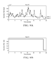
FIG. 9A illustrates a suspension height signal with two corresponding thresholds, and FIG. 9B illustrates the resulting secondary ride index values based on the comparison of the suspension height signal and the thresholds.
FIG. 10 illustrates a combined plot of the raw road roughness as determined from the suspension height sensors, a resulting secondary ride context signal, and a resulting suspension mode request signal.
FIG. 11A illustrates a plot of lateral acceleration of the vehicle derived from a conversion of the data from the suspension height sensors, and FIG. 11B illustrates a resulting road curvature signal and the resulting road curvature index.
FIGS. 12A-12C illustrate a comparison of the road curvature and curvature index from FIG. 11B, a resulting suspension index value and electronic power steering mode indexed value for arbitration into what mode the vehicle should be operating in.
DETAILED DESCRIPTION
Embodiments of the present disclosure are described herein. It is to be understood, however, that the disclosed embodiments are merely examples and other embodiments can take various and alternative forms. The figures are not necessarily to scale; some features could be exaggerated or minimized to show details of particular components. Therefore, specific structural and functional details disclosed herein are not to be interpreted as limiting, but merely as a representative basis for teaching one skilled in the art to variously employ the embodiments. As those of ordinary skill in the art will understand, various features illustrated and described with reference to any one of the figures can be combined with features illustrated in one or more other figures to produce embodiments that are not explicitly illustrated or described. The combinations of features illustrated provide representative embodiments for typical applications. Various combinations and modifications of the features consistent with the teachings of this disclosure, however, could be desired for particular applications or implementations.
FIG. 1 illustrates an overall block diagram of an Adaptive Drive Control (ADC) system 10 that can control various subsystems within the vehicle. As will be described further below, the ADC can change the operational mode of the vehicle, thereby affecting the instructions and commands given to the various subsystems to deliver a desired operational function. For example, the ADC can change the vehicle from a “normal” mode to a “sport” mode, in which the power-steering may become more sensitive, the suspension may tighten, and other subsystems may change accordingly. “Sport,” “normal,” and “comfort” are three exemplary modes that can be automatically selected to adapt to conditions of road surface conditions and road geometry changes such as curve.
The ADC has three primary inputs—driver input 12 (e.g., driver manually selecting a drive mode), sensed road measurements 14, and risk factors 16 relating to the risk of changing operational modes during certain driving conditions. At least one processor or controller 18 then provides an arbitration function at 20 and, based on these three inputs, automatically determines via various algorithms which operational mode to enter at 22. Once the operational mode is entered, the instructions and controls given to the subsystems (e.g., Continuous Controlled Damper (CCD) or suspension system 24, Electronic Power-Steering Assist (EPAS) System 26, and Powertrain Control (PT) System 28) are alter to such that the driving characteristics alter accordingly.
FIG. 2 illustrates a block diagram for the road condition sensing at 14. This can also be referred to as a road variation detection, as various inputs indicate the changes in the characteristics of the road. According to various aspects of the present disclosure, Road Variation Indexes (RVIs) are calculated based on the various road variation or condition detections.
As will be described below, the RVIs are formed from raw sensor measurements that are used for variable vehicle functions but can be mathematically but indirectly related to the characteristics of the road conditions, and classify the computations based on the raw sensor measurements to better capture whether the road is rough, smooth, curved, etc. These index values are ultimately available to the arbitration logic 20 for automatic mode selection. The arbitration logic 20 then commands the mode to either hold or change at 22 based on these index values. If the arbitration logic 20 commands the drive mode to change, the commands given to the various subsystems 24, 26, 28 change accordingly.
The raw sensor measurements for estimating road surface conditions can be determined via a suspension system, shown generally in FIG. 3, together with the on-board sensor measurements for the other control functions. The suspension system 100 includes a strut assembly and a shock absorber 102, such as a coil spring, located at each wheel. Suspension height sensors 104 are located along each strut assembly and are configured to indicate the relative displacement between the wheel center and the connecting point of the vehicle body. The Road Variation Indexes can then be calculated based on information derived from the four suspension height sensors, together with the other measurements and computed variables from the other sensor measurements.
For example, data from the suspension height sensors 104 can be used to calculate the vertical displacement of a wheel/tire corner using the car models shown in FIGS. 4-5. This can be used to characterize the vertical vibration or motion of the wheel/tire corner under the influence of road surface roughness or road surface variations or road conditions. The suspension height sensors 104 can also be used to compute the vehicle body motions in roll, pitch and yaw directions and their values with respect to the average plane of the road surface. See, for example, U.S. Pat. No. 6,684,140, which is incorporated by reference herein. This patent illustrates one exemplary system for computing primary motion of the vehicle body under the influence of the road undulations or the driver's maneuvering, which is also illustrated in FIGS. 4-5. The sensors of the vehicle suspension together with the other measured and computed variables, for example, can be categorized to determine different categories of road surface conditions that excite vehicle body motions in pitch, roll, heave, and yaw directions.
FIG. 4 illustrates the value Fsusp that is the suspension height measure. The term Cs represents the damping coefficient of the suspension system and is controlled electronically by the ADC to alter the suspension mode, i.e. sport, normal, luxury, etc. On some vehicles the spring coefficient Ks may be controlled electronically and there may be other devices such as devices to that produce additional forces.
FIG. 4 is a one wheel model, referred to as a quarter model. Quarter models can be combined into half vehicle models for modeling roll/pitch and half vehicle models can be combined into whole vehicle models to model heave. These models are used to develop the control algorithms that provide the inputs for road index calculations (FIG. 1). Half and whole vehicle models have not been illustrated.
Referring back to FIG. 2 specifically, the Road Indexes are based on road curvature detections 30 and road surface variation detections 32 (as indicated by the suspension height sensors, for example). The resulting index values include road curvature indexes and road surface variation indexes, which are calculated at 34 and are further described below.
Regarding the road curvature detections 30, the road curvature variation index combines measurements of vehicle speed and vehicle yaw rate. The vehicle speed can be determined from wheel speed sensors together with the other measured and computed signals, and the yaw rate can be received from the Electronic Stability Control (ESC) system, as described above. Vehicle lateral acceleration can also be used. Calculations of the road curvature index values will be described further below with regard to FIGS. 12A-C.
Regarding the road surface variation detections 32, or road roughness detections, the road surface variation detection is broken into a primary road roughness detection and a secondary road roughness detection. The primary road roughness detections include those that excite the vehicle body motions through determining the pitch angle, heave, and roll angle of the vehicle body with respect to the average road surface, as explained with reference to FIG. 5 above or U.S. Pat. No. 6,684,140. Passing the magnitude of those computed variables through band-pass filters will provide variables that can be used to assemble certain indexes, referred to as Primary Ride Indexes. The conversion of primary road roughness detection into Primary Ride Indexes is explained below with reference to FIGS. 7-8.
Likewise, the secondary road roughness detection and determinations, and the conversion of these detections into Secondary Ride Indexes, is explained below with reference to FIGS. 9-10.
Before describing in detail the methods and control algorithms for computing the Road Variation Indexes, an exemplary control system affected by the RVIs is illustrated in FIG. 6. In particular, an exemplary Electronic Power-Steering Assist (EPAS) subsystem 26 is illustrated. The EPAS subsystem 26 includes its own EPAS controller 200 that is communicatively coupled to the ADC controller 18, as explained with reference to FIG. 1 above. The ADC controller 18 provides the EPAS controller 200 with instructions depending upon which mode of operation (e.g., sport, normal, comfort) the ADC determines to be appropriate. Based on these instructions, the EPAS controller 200 provides commands to a power-steering motor 202. The motor 202 is coupled to a steering linkage 204 and used to assist in the turning of a pair of wheels 206. The steering linkage 204 may include, for example, a rack and pinion coupling, generally shown at 208. The power-steering motor 202 is configured to provide torque into the steering system to turn the wheels 206 while the driver turns a steering wheel 210. For example, a steering wheel sensor 212 detects the position of the steering wheel 210 and sends a signal indicating this position to the EPAS controller 200. The EPAS controller 200 then uses this signal to control the motor 202 accordingly to assist turning of the wheels 206.
In one embodiment, the calculated RVIs are used to alter the mode of operation of the ADC controller 18 as the road conditions change. This in turn alters the instructions sent to the EPAS controller 200 such that the motor 202 is used to assist the turning of the wheels 206 in a different fashion. For example, if the RVIs indicate a change in mode of operation from “normal” to “sport,” the instructions sent to the EPAS controller 200 alter accordingly, causing the motor 202 to correspondingly modify its relative output as the steering wheel 210 is turned.
Other such examples are contemplated by using the RVIs to control the Continuously Controlled Damper (CCD) 24 and the Powertrain Control System 28 as the mode of operation changes due to the indexed values of the RVIs. For example, the CCD System 24 may include a control module responsible for commanding a necessary amount damping according to various RVIs and operational mode commands. Furthermore, the Powertrain Control System 28 may include a control module(s) responsible for controlling an engine, one or more electric motors, a transmission, a torque converter, and other such mechanisms in a powertrain. A change in operational mode for the Powertrain Control System 28 may, for example, alter the shift schedule of the transmission or the delay or responsiveness in the torque output from the engine or electric motor.
Referring to FIGS. 7A and 7B, illustrates an exemplary calculation of one of the primary RVIs—the pitch-heave index. In this particular example, FIG. 7A illustrates a computed vehicle body heave signal that is generated through band-passing the magnitude of the heave variable received from the suspension height sensors 104 across multiple wheels. This signal quantitatively indicates the heave motion of the vehicle body while traveling over a road surface. A similar signal can also be generated which indicates the pitch of the vehicle body, by comparing the suspension height measurements across multiple wheels.
Two thresholds are provided in FIG. 7A, namely, a first threshold (threshold_1) and a second threshold (threshold_2). These two thresholds are used to characterize the band-pass filtered magnitude of the computed vehicle body heave and pitch signals into a pitch-heave index. These thresholds are also tunable across vehicle platforms, and may also be tunable based on which driving mode the vehicle is currently operating in. In the example shown in FIG. 7A, the first threshold is about 0.01 m, as the second threshold is about 0.005 m.
The index value calculated in FIG. 7B is either 0 or 1. Additional integer index values may be given, as will be discussed below with regard to other embodiments. As the suspension height remains below the first threshold, e.g., between t=0 and t=10 seconds, the pitch-heave index remains 0. At about t=10 seconds, the suspension height exceeds the first threshold, also referred to as an activation threshold. Exceeding the activation threshold causes the pitch-heave RVI to change from 0 to 1, or “activate.” The index value then remains at 1 until the suspension height signal falls below the second threshold. In the embodiment shown in FIGS. 7A-7B, the index value remains at 1 until the suspension height signal remains below the second threshold for a predetermined time (e.g., 2 seconds). This is analogous to a hysteresis being provided for the threshold, such that a transition delay from 1 to 0 is provided to account for ride input frequencies commonly observed when driving over a road surface. For example, as can be seen, the index value remains at 1 until about t=16 seconds due to the suspension height signal being below the second threshold from about t=14 seconds to t=16 seconds. Thereafter, the RVI index value increases back to 1 again at about t=17 seconds, due to the suspension height signal exceeding the first threshold again.
FIG. 8A represents primary heave and pitch signals, as detected from the suspension height sensors, after being passed through a band-pass filter, and resulting magnitudes of the signals that result in pitch and heave roughness. After these signals are sent through the arbitration function 20, the resulting discretized signals are illustrated in FIG. 8B. FIG. 8B is an output of the arbitration function 20 that leads the controller to determine which mode to enter at 22. For example, initially (e.g., between 0 and 1 second) the road is relatively smooth, keeping the mode request signal in FIG. 8B at a default level, e.g., Level 5. As the magnitude of the primary heave signal increases, the resulting suspension mode request changes incrementally from 5 to 4 to 3. The duration of the time the mode request is kept on each discrete level can be calibrated such that the rate of transition between steps is controlled. By moving between steps, the controller can determine which mode to enter based on which stepped level the suspension mode request signal is on.
In the embodiment illustrated in FIGS. 8A and 8B, as the rate of change of the magnitude of the heave of the vehicle fluctuates, the mode request fluctuates accordingly. For example, high amounts of road surface conditions cause the filtered pitch signals to abruptly spike around 12 seconds, 17 seconds and 22 seconds. At these times, the resulting suspension mode changes towards stepped level 8 and away from the default level 5. A resulting signal can be sent to indicate the automatic desire for the vehicle to enter a “Sport” mode rather than the default driving mode when the mode request is on stepped level 5.
The RVI determined in FIG. 7B is merely exemplary of one primary road index—the pitch-heave index. Another primary index value—a roll index—can be computed using suspension height signals and algorithms using such signals to indicate vehicular roll. The roll RVI is another primary road index value.
Secondary road index values are also computed, as explained above with regard to FIG. 2. The secondary ride index can also indicate road roughness. FIG. 9A shows a raw suspension height signal, and FIG. 9B shows a resulting secondary ride index value based on the suspension height. The secondary ride or roughness signal is calculated from a bandpass filtered magnitude of a signal determined by comparing the suspension height measurements across multiple wheels. Similar to FIGS. 7A-7B, two thresholds are again provided. As the suspension height (secondary ride or roughness signal) exceeds the first threshold (e.g., 0.2 m), the index value remains at 1, or remains “active.” The index value does not change to 0 (or “deactivate) until the suspension height falls below the second threshold (e.g., 0.1 m). In this particular embodiment, the secondary ride index is not computed with a transition delay. In other words, as soon as the suspension height falls below the second threshold, the secondary ride index falls to 0 without first requiring that the suspension height remain below the second threshold for a certain time. In other practical uses, such as traveling over frost heaves, the transition delay can be provided.
FIG. 10 illustrates a combined plot of the raw secondary ride or road roughness signals as determined from the suspension height sensors, and the resulting secondary ride context signal going from stepped level 5 to 4 as well as the resulting suspension mode request signals decreasing from the default stepped level 5 to 2. Based on the particular characteristics of this traveled road, the output mode request may automatically change from the default driving mode to another driving mode based on the magnitude of the suspension height signals.
The RVIs calculated and used in FIGS. 7-10 are road surface variation indexes, shown in FIG. 2 as being calculated from road surface conditions 32. Also shown in FIG. 2 are signals relating to road curvature at 30 that can be calculated and transformed into a road curvature index at 34. FIGS. 11-12 disclose such road curvature index calculations.
In FIG. 11A, the road curvature is computed from an estimate of the vehicle lateral acceleration, described above. This particular computation ignores the sign of the signal (cornering direction), focuses on the pure magnitude (positive or negative) of the signal, and includes filtering. As the magnitude of the signal increases above the threshold and remains above the threshold for a certain time, the road curvature index is at 1 rather than the default 0.
The road curvature signal plotted in FIG. 11B is created by combining the vehicle yaw rate and the vehicle's speed. For example, if the vehicle retains a constant speed, a higher yaw rate will indicate a higher curvature. In this embodiment, only one threshold is shown. As the road curvature exceeds the threshold, a road curvature index is altered from 0 to 1. This RVI is not changed back to 0 unless and until the road curvature falls below the threshold for a predetermined amount of time.
It should be understood, as evident from the differences between the graphical representations in the present disclosure, that the use of thresholds can vary across different embodiments. One or multiple thresholds may be present, and the RVI can change between 0 and 1 (or a larger number of steps) accordingly as the road curvature or road surface variation signals exceed and fall below the one or two thresholds. Also, time delay or hysteresis may be provided in only some embodiments. For example, the embodiments in FIGS. 7A-7B include a time delay such that the suspension height signal must be below the second threshold for a certain time amount for the corresponding RVI to change from 1 to 0; such a time delay is not present in the embodiments in FIGS. 9A-9B.
FIG. 12A is a reproduction of the road curvature signal and its associated road curvature index. FIGS. 12B and 12C illustrate the change in commands for the electronic power-steering assist system and the CCD system based on the road curvature changing.
Utilizing the teachings of the present disclosure, it is possible to characterize, index, discretize, or otherwise convert raw signals responsive to the driving conditions into certain RVIs that are in integer form. In other words, the road curvature signals or road surface variation signals can be converted into discrete values (“discretized”), such as two or more integers that represent Road Variation Indexes (RVIs). At least one processor then conducts an algorithm arbitration that takes into account each of the RVIs as the vehicle is driven. Based on the combinations and/or variations in the determined RVIs, the at least one processor can correspondingly alter the operational mode of the vehicle (e.g., “sport,” “normal,” “comfort,” etc.) such that the commands given to the subsystem components (continuously controlled damping, power-steering, or powertrain components) change. In short, the system is configured to discretize or index road curvature and road surface signals, and alter the operational mode of a subsystem based on the discretized or indexed value.
The processes, methods, or algorithms disclosed herein can be deliverable to/implemented by a processing device, controller, or computer, which can include any existing programmable electronic control unit or dedicated electronic control unit. Similarly, the processes, methods, or algorithms can be stored as data and instructions executable by a controller or computer in many forms including, but not limited to, information permanently stored on non-writable storage media such as ROM devices and information alterably stored on writeable storage media such as floppy disks, magnetic tapes, CDs, RAM devices, and other magnetic and optical media. The processes, methods, or algorithms can also be implemented in a software executable object. Alternatively, the processes, methods, or algorithms can be embodied in whole or in part using suitable hardware components, such as Application Specific Integrated Circuits (ASICs), Field-Programmable Gate Arrays (FPGAs), state machines, controllers or other hardware components or devices, or a combination of hardware, software and firmware components.
While exemplary embodiments are described above, it is not intended that these embodiments describe all possible forms encompassed by the claims. The words used in the specification are words of description rather than limitation, and it is understood that various changes can be made without departing from the spirit and scope of the disclosure. As previously described, the features of various embodiments can be combined to form further embodiments of the invention that may not be explicitly described or illustrated. While various embodiments could have been described as providing advantages or being preferred over other embodiments or prior art implementations with respect to one or more desired characteristics, those of ordinary skill in the art recognize that one or more features or characteristics can be compromised to achieve desired overall system attributes, which depend on the specific application and implementation. These attributes can include, but are not limited to cost, strength, durability, life cycle cost, marketability, appearance, packaging, size, serviceability, weight, manufacturability, ease of assembly, etc. As such, embodiments described as less desirable than other embodiments or prior art implementations with respect to one or more characteristics are not outside the scope of the disclosure and can be desirable for particular applications.

Claims (18)

What is claimed is:
1. A control system of a vehicle, comprising:
an adaptive drive controller programmed to control a continuously controlled damping and spring subsystem according to an operational mode;
a plurality of sensors configured to sense road surface conditions associated with a road surface on which the vehicle travels; and
at least one controller programmed to alter the operational mode based on a discretization of the road surface conditions into more than two discrete values.
2. The control system of claim 1, wherein the at least one controller is further programmed to discretize the sensed road surface conditions into a first discrete value based on the sensed road surface conditions exceeding a first threshold.
3. The control system of claim 2, wherein the at least one controller is further programmed to discretize the sensed road surface conditions into a second discrete value based on the sensed road surface conditions being less than a second threshold.
4. The control system of claim 2, wherein the at least one controller is further programmed to discretize the sensed road surface conditions into a second discrete value based on the sensed road surface conditions being less than a second threshold for a predetermined amount of time.
5. The control system of claim 1, wherein the discretization includes indexed values indicating vehicle heave, pitch or roll.
6. The control system of claim 1, wherein the plurality of sensors includes a plurality of suspension height sensors each configured to sense the relative motions between the vehicle body and an associated involved wheel/tire assembly, and wherein signals generated by the suspension height sensors relate to the road surface conditions.
7. The control system of claim 1, wherein the plurality of sensors is further configured to sense road curvature associated with the road surface and wherein the at least one controller is further programmed to alter the operational mode based on a discretization of the sensed road curvature.
8. A control system of a vehicle, comprising:
an electronic power-steering controller programmed to control an electronic power-steering subsystem according to an operational mode;
a plurality of sensors configured to sense road surface conditions associated with a road surface on which the vehicle travels; and
at least one controller programmed to alter the operational mode based on a discretization of the road surface conditions into more than two discrete values.
9. The control system of claim 8, wherein the plurality of sensors is further configured to sense road curvature associated with the road surface and wherein the at least one controller is further programmed to alter the operational mode based on a discretization of the sensed road curvature.
10. The control system of claim 8, wherein the at least one controller is further programmed to discretize the sensed road surface conditions into a first discrete value based on the sensed road surface conditions exceeding a first threshold.
11. The control system of claim 10, wherein the at least one controller is further programmed to discretize the sensed road surface conditions into a second discrete value based on the sensed road surface conditions being less than a second threshold.
12. The control system of claim 10, wherein the at least one controller is further programmed to discretize the sensed road surface conditions into a second discrete value based on the sensed road surface conditions being less than a second threshold for a predetermined amount of time.
13. A vehicle comprising:
a powertrain controller programmed to operate in a plurality of modes and to provide a powertrain with operational instructions that vary according to which one of the modes the powertrain controller is operating in;
a plurality of sensors configured to sense road surface conditions associated with a road surface on which the vehicle travels; and
at least one controller programmed to alter the one of the modes the powertrain controller is operating in based on a discretization of the sensed road surface conditions into more than two discrete values.
14. The vehicle of claim 13, wherein the plurality of sensors includes a plurality of suspension height sensors each configured to sense the displacement of a corresponding wheel and wherein signals generated by the suspension height sensors relate to the road surface conditions.
15. The vehicle of claim 13, wherein the plurality of sensors is further configured to sense road curvature associated with the road surface.
16. The vehicle of claim 13, wherein the at least one controller is further programmed to discretize the sensed road surface conditions into a first discrete value based on the sensed road surface conditions exceeding a first threshold.
17. The vehicle of claim 16, wherein the at least one controller is further programmed to discretize the sensed road surface conditions into a second discrete value based on the sensed road surface conditions being less than a second threshold.
18. The vehicle of claim 16, wherein the at least one controller is further programmed to discretize the sensed road surface conditions into a second discrete value based on the sensed road surface conditions being less than a second threshold for a predetermined amount of time.
US14/618,077 2015-02-10 2015-02-10 Enhanced road characterization for adaptive mode drive Active US9522586B2 (en)

Priority Applications (5)

Application Number Priority Date Filing Date Title
US14/618,077 US9522586B2 (en) 2015-02-10 2015-02-10 Enhanced road characterization for adaptive mode drive
DE102016101283.1A DE102016101283A1 (en) 2015-02-10 2016-01-26 ADVANCED ROAD CHARACTERIZATION FOR ADAPTIVE MODE CONTROL
RU2016103407A RU2707483C2 (en) 2015-02-10 2016-02-03 Improved determination of road characteristics for adaptive driving mode
MX2016001775A MX2016001775A (en) 2015-02-10 2016-02-09 Enhanced road characterization for adaptive mode drive.
CN201610084544.XA CN105857296B (en) 2015-02-10 2016-02-14 Enhanced road characterization for adaptive mode driving

Applications Claiming Priority (1)

Application Number Priority Date Filing Date Title
US14/618,077 US9522586B2 (en) 2015-02-10 2015-02-10 Enhanced road characterization for adaptive mode drive

Publications (2)

Publication Number Publication Date
US20160229252A1 US20160229252A1 (en) 2016-08-11
US9522586B2 true US9522586B2 (en) 2016-12-20

Family

ID=56498627

Family Applications (1)

Application Number Title Priority Date Filing Date
US14/618,077 Active US9522586B2 (en) 2015-02-10 2015-02-10 Enhanced road characterization for adaptive mode drive

Country Status (5)

Country Link
US (1) US9522586B2 (en)
CN (1) CN105857296B (en)
DE (1) DE102016101283A1 (en)
MX (1) MX2016001775A (en)
RU (1) RU2707483C2 (en)

Cited By (2)

* Cited by examiner, † Cited by third party
Publication number Priority date Publication date Assignee Title
US20170087951A1 (en) * 2015-09-29 2017-03-30 Ford Global Technologies, Llc Obstacle avoidance system with active suspensions
US10112642B2 (en) * 2015-10-06 2018-10-30 Mando Corporation Steering control apparatus and steering control method

Families Citing this family (20)

* Cited by examiner, † Cited by third party
Publication number Priority date Publication date Assignee Title
DE102015011517B3 (en) * 2015-09-03 2016-09-08 Audi Ag Method for determining a current level position of a vehicle
US9713947B2 (en) * 2015-09-17 2017-07-25 GM Global Technology Operations LLC Vehicle ride-height determination for control of vehicle aerodynamics
DE102016217654A1 (en) * 2016-09-15 2018-03-15 Bayerische Motoren Werke Aktiengesellschaft Method and data processing system for generating map data of a digital map
US10220851B2 (en) 2016-12-14 2019-03-05 Ford Global Technologies, Llc Infrastructure-centric vehicle mode selection
CN109476310B (en) * 2016-12-30 2021-11-12 同济大学 Automatic driving vehicle speed control method based on comfort level
US10737544B2 (en) * 2017-07-24 2020-08-11 Ford Global Technologies, Llc Systems and methods to control a suspension of a vehicle
US11708109B2 (en) * 2017-09-27 2023-07-25 Hitachi Astemo, Ltd. Vehicle control system
US11292307B2 (en) * 2019-09-23 2022-04-05 GM Global Technology Operations LLC Suspension fault diagnostics and prognostics using pitch and roll model
US20210191413A1 (en) * 2019-12-18 2021-06-24 Caterpillar Paving Products Inc. Machine Sunk Detection System and Method
JP7180638B2 (en) 2020-06-08 2022-11-30 トヨタ自動車株式会社 VEHICLE RUNNING STATE CONTROL DEVICE AND METHOD
JP7469167B2 (en) * 2020-07-07 2024-04-16 本田技研工業株式会社 Control device, control method, and vehicle
GB2597456B (en) * 2020-07-21 2022-11-02 Jaguar Land Rover Ltd Vehicle active suspension control system and method
GB2601344B (en) * 2020-11-27 2023-05-03 Jaguar Land Rover Ltd Active suspension control on repeating surface undulations
WO2022178654A1 (en) * 2021-02-23 2022-09-01 浙江吉利控股集团有限公司 Driving method for hybrid vehicle, system, and hybrid vehicle
CN113386735B (en) * 2021-06-17 2022-10-21 岚图汽车科技有限公司 Vehicle control method and device
US11859571B2 (en) * 2021-07-21 2024-01-02 Ford Global Technologies, Llc Methods for a road surface metric
CN115158282B (en) * 2022-06-28 2024-06-18 一汽奔腾轿车有限公司 An active safety system to reduce the risk of vehicle yaw loss of control during high-speed driving
IT202200022356A1 (en) * 2022-10-31 2024-05-01 Ferrari Spa MOTOR VEHICLE AND METHOD OF DETECTING A PARAMETER ASSOCIATED WITH A ROAD SURFACE SURFACE CONDITION
CN116620388A (en) * 2023-06-12 2023-08-22 上海拿森汽车电子有限公司 A control method, device, and computer storage medium for a vehicle power steering system
US12447947B2 (en) 2024-03-14 2025-10-21 GM Global Technology Operations LLC Road condition detection using suspension sensors

Citations (8)

* Cited by examiner, † Cited by third party
Publication number Priority date Publication date Assignee Title
US5410477A (en) 1991-03-22 1995-04-25 Hitachi, Ltd. Control system for an automotive vehicle having apparatus for predicting the driving environment of the vehicle
US6202020B1 (en) * 1999-08-20 2001-03-13 Meritor Heavy Vehicle Systems, Llc Method and system for determining condition of road
US6952637B2 (en) 2000-09-09 2005-10-04 Kelsey-Hayes Company Rough road detection using suspension system information
US20100019964A1 (en) 2008-07-24 2010-01-28 Gm Global Technology Operations, Inc. Adaptive vehicle control system with driving style recognition and road condition recognition
US20100152951A1 (en) 2008-12-15 2010-06-17 Gm Global Technology Operations, Inc. Adaptive vehicle control system with driving style recognition based on vehicle accelerating and decelerating
US20120203424A1 (en) * 2011-02-05 2012-08-09 Ford Global Technologies, Llc System and method for integrated control of vehicle control systems
WO2013120546A1 (en) 2012-02-13 2013-08-22 Jaguar Cars Ltd Driver advice system for a vehicle
CN203283230U (en) 2013-05-28 2013-11-13 万向钱潮股份有限公司 Automatic road unevenness identification system for vehicle

Family Cites Families (8)

* Cited by examiner, † Cited by third party
Publication number Priority date Publication date Assignee Title
JPH05345509A (en) * 1992-06-15 1993-12-27 Oki Electric Ind Co Ltd Suspension controller
JPH11192826A (en) * 1997-12-26 1999-07-21 Tokico Ltd Suspension control device
US6684140B2 (en) 2002-06-19 2004-01-27 Ford Global Technologies, Llc System for sensing vehicle global and relative attitudes using suspension height sensors
ATE431264T1 (en) * 2003-09-26 2009-05-15 Aisin Aw Co SYSTEM AND METHOD FOR CONTROLLING A VEHICLE SUSPENSION
KR100715594B1 (en) * 2003-10-15 2007-05-10 주식회사 만도 Damping force control method of electronically controlled suspension system
US8285447B2 (en) * 2007-03-20 2012-10-09 Enpulz, L.L.C. Look ahead vehicle suspension system
JP5937921B2 (en) * 2012-08-09 2016-06-22 株式会社ブリヂストン Road surface condition determination method and apparatus
CN104768782B (en) * 2012-11-07 2018-05-08 北极星工业有限公司 Vehicle with the suspension with continuous damping control

Patent Citations (9)

* Cited by examiner, † Cited by third party
Publication number Priority date Publication date Assignee Title
US5410477A (en) 1991-03-22 1995-04-25 Hitachi, Ltd. Control system for an automotive vehicle having apparatus for predicting the driving environment of the vehicle
US6202020B1 (en) * 1999-08-20 2001-03-13 Meritor Heavy Vehicle Systems, Llc Method and system for determining condition of road
US6952637B2 (en) 2000-09-09 2005-10-04 Kelsey-Hayes Company Rough road detection using suspension system information
US20100019964A1 (en) 2008-07-24 2010-01-28 Gm Global Technology Operations, Inc. Adaptive vehicle control system with driving style recognition and road condition recognition
US20100152951A1 (en) 2008-12-15 2010-06-17 Gm Global Technology Operations, Inc. Adaptive vehicle control system with driving style recognition based on vehicle accelerating and decelerating
US20120203424A1 (en) * 2011-02-05 2012-08-09 Ford Global Technologies, Llc System and method for integrated control of vehicle control systems
US8600614B2 (en) 2011-02-05 2013-12-03 Ford Global Technologies, Llc System and method for integrated control of vehicle control systems
WO2013120546A1 (en) 2012-02-13 2013-08-22 Jaguar Cars Ltd Driver advice system for a vehicle
CN203283230U (en) 2013-05-28 2013-11-13 万向钱潮股份有限公司 Automatic road unevenness identification system for vehicle

Cited By (3)

* Cited by examiner, † Cited by third party
Publication number Priority date Publication date Assignee Title
US20170087951A1 (en) * 2015-09-29 2017-03-30 Ford Global Technologies, Llc Obstacle avoidance system with active suspensions
US10293653B2 (en) * 2015-09-29 2019-05-21 Ford Global Technologies, Llc Obstacle avoidance system with active suspensions
US10112642B2 (en) * 2015-10-06 2018-10-30 Mando Corporation Steering control apparatus and steering control method

Also Published As

Publication number Publication date
RU2707483C2 (en) 2019-11-26
US20160229252A1 (en) 2016-08-11
RU2016103407A3 (en) 2019-05-31
MX2016001775A (en) 2016-08-30
CN105857296A (en) 2016-08-17
RU2016103407A (en) 2017-08-08
DE102016101283A1 (en) 2016-08-11
CN105857296B (en) 2023-10-03

Similar Documents

Publication Publication Date Title
US9522586B2 (en) Enhanced road characterization for adaptive mode drive
US12325432B2 (en) System and method for controlling a vehicle
JP5234224B1 (en) Vehicle control device
US11738758B2 (en) Apparatus and method for monitoring vehicle operation
CN103764471B (en) Controller of vehicle
JP2009508751A (en) SUSPENSION CONTROL DEVICE, VEHICLE EQUIPPED WITH SAME DEVICE, IMPLEMENTATION METHOD AND PROGRAM
US20140032068A1 (en) Estimation of road inclination
GB2499461A (en) Cruise control which sets a speed ceiling when off-road driving is detected
JP2009508753A (en) Suspension control device, vehicle equipped with the device, manufacturing method, and program
CN104853966A (en) Method for Determining the Ideal Turning Inclination of a Motor Vehicle Driving Through a Curved Road Section
JP2009508752A (en) SUSPENSION CONTROL DEVICE, VEHICLE EQUIPPED WITH SAME DEVICE, IMPLEMENTATION METHOD AND PROGRAM
JP2009508750A (en) SUSPENSION CONTROL DEVICE, VEHICLE EQUIPPED WITH SAME DEVICE, IMPLEMENTATION METHOD AND PROGRAM
CN115023355A (en) Look-ahead control of vehicle systems
US20200001849A1 (en) Methods and systems for brake pad life determination
CN109311361A (en) Method and control device for controlling at least one shock absorber of a motor vehicle
CN106541989A (en) Motor turning device and the method for calculating the control signal for servo unit
US20140343815A1 (en) Vehicle control system
EP3002139B1 (en) Damper control system
KR20100126892A (en) Continuously variable MR damper control system using body acceleration and relative displacement of damper
JP2013086733A (en) Driving force control device of vehicle
GB2591036A (en) Apparatus and method for monitoring vehicle operation

Legal Events

Date Code Title Description
AS Assignment

Owner name: FORD GLOBAL TECHNOLOGIES, LLC, MICHIGAN

Free format text: ASSIGNMENT OF ASSIGNORS INTEREST;ASSIGNORS:LU, JIANBO;SZWABOWSKI, STEVEN JOSEPH;PRAKAH-ASANTE, KWAKU O.;AND OTHERS;SIGNING DATES FROM 20150126 TO 20150203;REEL/FRAME:034930/0028

STCF Information on status: patent grant

Free format text: PATENTED CASE

MAFP Maintenance fee payment

Free format text: PAYMENT OF MAINTENANCE FEE, 4TH YEAR, LARGE ENTITY (ORIGINAL EVENT CODE: M1551); ENTITY STATUS OF PATENT OWNER: LARGE ENTITY

Year of fee payment: 4

MAFP Maintenance fee payment

Free format text: PAYMENT OF MAINTENANCE FEE, 8TH YEAR, LARGE ENTITY (ORIGINAL EVENT CODE: M1552); ENTITY STATUS OF PATENT OWNER: LARGE ENTITY

Year of fee payment: 8