JP2009508751A - SUSPENSION CONTROL DEVICE, VEHICLE EQUIPPED WITH SAME DEVICE, IMPLEMENTATION METHOD AND PROGRAM - Google Patents
SUSPENSION CONTROL DEVICE, VEHICLE EQUIPPED WITH SAME DEVICE, IMPLEMENTATION METHOD AND PROGRAM Download PDFInfo
- Publication number
- JP2009508751A JP2009508751A JP2008531749A JP2008531749A JP2009508751A JP 2009508751 A JP2009508751 A JP 2009508751A JP 2008531749 A JP2008531749 A JP 2008531749A JP 2008531749 A JP2008531749 A JP 2008531749A JP 2009508751 A JP2009508751 A JP 2009508751A
- Authority
- JP
- Japan
- Prior art keywords
- vehicle
- drag
- modal
- calculating
- stress
- Prior art date
- Legal status (The legal status is an assumption and is not a legal conclusion. Google has not performed a legal analysis and makes no representation as to the accuracy of the status listed.)
- Pending
Links
Images


Classifications
-
- B—PERFORMING OPERATIONS; TRANSPORTING
- B60—VEHICLES IN GENERAL
- B60G—VEHICLE SUSPENSION ARRANGEMENTS
- B60G17/00—Resilient suspensions having means for adjusting the spring or vibration-damper characteristics, for regulating the distance between a supporting surface and a sprung part of vehicle or for locking suspension during use to meet varying vehicular or surface conditions, e.g. due to speed or load
- B60G17/015—Resilient suspensions having means for adjusting the spring or vibration-damper characteristics, for regulating the distance between a supporting surface and a sprung part of vehicle or for locking suspension during use to meet varying vehicular or surface conditions, e.g. due to speed or load the regulating means comprising electric or electronic elements
- B60G17/018—Resilient suspensions having means for adjusting the spring or vibration-damper characteristics, for regulating the distance between a supporting surface and a sprung part of vehicle or for locking suspension during use to meet varying vehicular or surface conditions, e.g. due to speed or load the regulating means comprising electric or electronic elements characterised by the use of a specific signal treatment or control method
-
- B—PERFORMING OPERATIONS; TRANSPORTING
- B60—VEHICLES IN GENERAL
- B60G—VEHICLE SUSPENSION ARRANGEMENTS
- B60G17/00—Resilient suspensions having means for adjusting the spring or vibration-damper characteristics, for regulating the distance between a supporting surface and a sprung part of vehicle or for locking suspension during use to meet varying vehicular or surface conditions, e.g. due to speed or load
- B60G17/015—Resilient suspensions having means for adjusting the spring or vibration-damper characteristics, for regulating the distance between a supporting surface and a sprung part of vehicle or for locking suspension during use to meet varying vehicular or surface conditions, e.g. due to speed or load the regulating means comprising electric or electronic elements
- B60G17/016—Resilient suspensions having means for adjusting the spring or vibration-damper characteristics, for regulating the distance between a supporting surface and a sprung part of vehicle or for locking suspension during use to meet varying vehicular or surface conditions, e.g. due to speed or load the regulating means comprising electric or electronic elements characterised by their responsiveness, when the vehicle is travelling, to specific motion, a specific condition, or driver input
- B60G17/0165—Resilient suspensions having means for adjusting the spring or vibration-damper characteristics, for regulating the distance between a supporting surface and a sprung part of vehicle or for locking suspension during use to meet varying vehicular or surface conditions, e.g. due to speed or load the regulating means comprising electric or electronic elements characterised by their responsiveness, when the vehicle is travelling, to specific motion, a specific condition, or driver input to an external condition, e.g. rough road surface, side wind
-
- B—PERFORMING OPERATIONS; TRANSPORTING
- B60—VEHICLES IN GENERAL
- B60G—VEHICLE SUSPENSION ARRANGEMENTS
- B60G3/00—Resilient suspensions for a single wheel
- B60G3/02—Resilient suspensions for a single wheel with a single pivoted arm
- B60G3/04—Resilient suspensions for a single wheel with a single pivoted arm the arm being essentially transverse to the longitudinal axis of the vehicle
-
- B—PERFORMING OPERATIONS; TRANSPORTING
- B60—VEHICLES IN GENERAL
- B60G—VEHICLE SUSPENSION ARRANGEMENTS
- B60G3/00—Resilient suspensions for a single wheel
- B60G3/18—Resilient suspensions for a single wheel with two or more pivoted arms, e.g. parallelogram
- B60G3/20—Resilient suspensions for a single wheel with two or more pivoted arms, e.g. parallelogram all arms being rigid
-
- B—PERFORMING OPERATIONS; TRANSPORTING
- B60—VEHICLES IN GENERAL
- B60G—VEHICLE SUSPENSION ARRANGEMENTS
- B60G2400/00—Indexing codes relating to detected, measured or calculated conditions or factors
- B60G2400/10—Acceleration; Deceleration
- B60G2400/102—Acceleration; Deceleration vertical
-
- B—PERFORMING OPERATIONS; TRANSPORTING
- B60—VEHICLES IN GENERAL
- B60G—VEHICLE SUSPENSION ARRANGEMENTS
- B60G2400/00—Indexing codes relating to detected, measured or calculated conditions or factors
- B60G2400/20—Speed
- B60G2400/202—Piston speed; Relative velocity between vehicle body and wheel
-
- B—PERFORMING OPERATIONS; TRANSPORTING
- B60—VEHICLES IN GENERAL
- B60G—VEHICLE SUSPENSION ARRANGEMENTS
- B60G2500/00—Indexing codes relating to the regulated action or device
- B60G2500/10—Damping action or damper
-
- B—PERFORMING OPERATIONS; TRANSPORTING
- B60—VEHICLES IN GENERAL
- B60G—VEHICLE SUSPENSION ARRANGEMENTS
- B60G2800/00—Indexing codes relating to the type of movement or to the condition of the vehicle and to the end result to be achieved by the control action
- B60G2800/90—System Controller type
- B60G2800/91—Suspension Control
Abstract
本発明は自動車の車体のサスペンションの制御装置に関する。本発明によれば、装置は、− 車体の少なくとも1つの絶対モーダル速度(Vmod)の関数としてショックアブソーバの第1設定モーダル抗力F1を計算する第1手段(21)と、− 車輪の平均面に対する車体の1つの相対モーダル速度(Vmod2)の関数としてショックアブソーバの第2設定モーダル抗力F2を計算する第2手段(34)と、− 車両に対する1つの応力を検出する手段(22)と、− 重み付け係数αを計算し、式 F=(1−α).F1+α.F2、に従ってショックアブソーバの設定モーダル抗力Fを計算する手段(23)とを含む。The present invention relates to a suspension control device for an automobile body. According to the invention, the device comprises:-first means (21) for calculating a first set modal drag F1 of the shock absorber as a function of at least one absolute modal velocity (V mod ) of the vehicle body; A second means (34) for calculating a second set modal drag force F2 of the shock absorber as a function of one relative modal velocity (V mod2 ) of the vehicle body with respect to the vehicle; -means (22) for detecting one stress on the vehicle; The weighting factor α is calculated and the formula F = (1−α). F1 + α. Means (23) for calculating a set modal drag force F of the shock absorber according to F2.
Description
本発明は自動車のサスペンションの制御装置に関する。 The present invention relates to an automobile suspension control apparatus.
本発明の適用分野は、ばねサスペンション、ハイドロニューマチックサスペンション、あるいはその他の種類のサスペンションを有する自動車に関する。 The field of application of the invention relates to motor vehicles having spring suspensions, hydropneumatic suspensions or other types of suspensions.
これらのサスペンションは、車両に搭載されたコンピュータによって制御されるアクチュエータによって調節可能な可変減衰則ショックアブソーバを各車輪上に有する。 These suspensions have variable damping law shock absorbers on each wheel that can be adjusted by an actuator controlled by a computer mounted on the vehicle.
コンピュータはセンサから供給される測定値を入力部で受け取り、これらの測定値を基にして、ショックアブソーバのアクチュエータの1つまたは複数の制御量を計算する。 The computer receives the measurement values supplied from the sensor at the input unit, and calculates one or more controlled variables of the actuator of the shock absorber based on these measurement values.
コンピュータは特に、たとえば垂直方向のモーダルポンピング加速度、縦軸周りのモーダルロール加速度および横軸周りのモーダルピッチ加速度など、走行中に車体が受ける加速度を考慮に入れる。 In particular, the computer takes into account accelerations experienced by the vehicle during travel, such as, for example, modal pumping acceleration in the vertical direction, modal roll acceleration about the vertical axis, and modal pitch acceleration about the horizontal axis.
コンピュータは積分により車体の対応するモーダル速度を計算する。 The computer calculates the corresponding modal velocity of the car body by integration.
コンピュータが、ポンピング時の垂直モーダル速度、ロール時のモーダル角速度、ピッチ時のモーダル角速度を0に向かわせるように制御を実施する装置が知られているが、この論理は一般に「Skyhook」と呼ばれ、車内の人間の快適性を向上させるものでなければならない。 There is known a device in which the computer controls the vertical modal velocity at the time of pumping, the modal angular velocity at the time of rolling, and the modal angular velocity at the time of pitch to 0. This logic is generally called “Skyhoe”. , Should improve human comfort in the car.
これらの装置についての問題の1つは、これらの装置では車両のロードホールディングが常に保証されるとは限らないことである。 One problem with these devices is that they do not always guarantee vehicle road holding.
実際、大きな応力のように状況によっては、Skyhook型の論理によって制御されるサスペンションは、タイヤへの垂直抗力を犠牲にして作動する。たとえば、地面のこぶでは、Skyhookは、垂直抗力を犠牲にして快適性を優先させるために、何よりもショックアブソーバの柔らかさを優先する。 In fact, in some situations, such as large stresses, the suspension controlled by Skyhook type logic operates at the expense of normal drag on the tire. For example, on the hump of the ground, Skyhook gives priority to the softness of the shock absorber, above all, in order to give priority to comfort at the expense of vertical drag.
同様に、車両の運転者から課される要請は、地面から来る車体に向けての抗力を全くまたはほとんど上昇させず、したがって安心感がほとんど感じられず、あるいは運転者に、自分の行動が車両に対して効果がなかった印象を与える。 Similarly, the demands imposed by the driver of the vehicle raise little or no drag against the vehicle body coming from the ground, so there is little sense of security, or the driver is Gives the impression that there was no effect.
したがって、車体の保持に重きを置きつつSkyhook論理によってもたらされる快適性もそれほど損ねずに道路プロフィールを車体が追跡するようにする論理の必要性が存在する。 Thus, there is a need for logic that allows the vehicle body to track the road profile without placing much of the comfort provided by Skyhook logic while placing emphasis on holding the vehicle body.
実際、車体が道路プロフィールしか追跡しないような論理は、道路の凹凸が全て車体および運転者に直接伝達されるので、サスペンションの快適性における諸要件に合致しなくなるであろう。 In fact, the logic that the vehicle body only tracks the road profile will not meet the requirements for suspension comfort, since all road irregularities are transmitted directly to the vehicle body and the driver.
本発明は、先行技術の欠点を解消し、Skyhook論理と車体保持論理の間のトレードオフを行うサスペンション制御装置を得ることを目的とする。 An object of the present invention is to obtain a suspension control device that eliminates the drawbacks of the prior art and performs a trade-off between Skyhook logic and vehicle body holding logic.
特に、本発明による制御装置内で用いられる論理は、ポンピング、ロール、ピッチなど、少なくとも1つの車体モードを処理しなければならない。 In particular, the logic used in the control device according to the invention must handle at least one body mode, such as pumping, roll, pitch, etc.
このために、本発明の第1の目的は、車輪上の自動車の車体のサスペンションの制御装置であって、サスペンションの少なくとも1つの可変ショックアブソーバのアクチュエータの制御量を、車両上で推定される少なくとも1つの車体モーダル速度の関数として計算されるショックアブソーバのモーダル設定抗力の関数として計算する手段を有するコンピュータを備えるサスペンション制御装置において、
− ショックアブソーバの第1設定モーダル抗力F1を、車両上で推定される、車体の少なくとも1つの絶対モーダル速度の関数として計算する第1手段と、
− ショックアブソーバの第2設定モーダル抗力F2を、車両上で推定される、車輪の平均面に対する車体の少なくとも1つの相対モーダル速度の関数として計算する第2手段と
− 車両に対する少なくとも1つの応力を検出する手段と
− 第1設定モーダル抗力F1と第2設定モーダル抗力F2の重み付け係数αを計算し、それにより式
F=(1−α).F1+α.F2
(式中、重み付け係数αは0以上、1以下であり、通常は0であり、少なくとも検出された応力が規定のしきい値を超えたとき、値1になる)に従ってショックアブソーバの設定モーダル抗力Fを計算する手段と
を備えることを特徴とするサスペンションの制御装置である。
To this end, a first object of the present invention is a control device for a suspension of an automobile body on a wheel, wherein a control amount of an actuator of at least one variable shock absorber of the suspension is estimated at least on the vehicle. In a suspension control device comprising a computer having means for calculating as a function of a modal set drag of a shock absorber calculated as a function of one vehicle body modal speed,
-A first means for calculating a first set modal drag F1 of the shock absorber as a function of at least one absolute modal velocity of the vehicle body estimated on the vehicle;
-A second means for calculating the second set modal drag F2 of the shock absorber as a function of at least one relative modal velocity of the vehicle body relative to the average plane of the wheels, estimated on the vehicle;-detecting at least one stress on the vehicle And means for calculating a weighting coefficient α of the first set modal drag F1 and the second set modal drag F2, so that the formula F = (1-α). F1 + α. F2
According to the formula, the weighting coefficient α is not less than 0 and not more than 1 and is usually 0, and is at least 1 when the detected stress exceeds a specified threshold value. A suspension control apparatus comprising: means for calculating F.
本発明によれば、第1計算手段は、第1のSkyhook論理、すなわち快適性論理を実施する。 According to the invention, the first calculating means implements a first Skyhook logic, ie comfort logic.
第2計算手段は、第2のRoadhook型論理、すなわち道路のプロフィールを追跡する論理を実施し、この論理は、車体保持論理または挙動論理とも呼ばれる。 The second calculation means implements a second load-hook type logic, that is, a logic for tracking a road profile, and this logic is also called body holding logic or behavior logic.
デフォルトでは、すなわち大半の時間は、第1の快適性論理が用いられる。第2の車体保持論理は、大きな応力が検出されたとき、一時的に第1の快適性論理の代りになる。 By default, ie most of the time, the first comfort logic is used. The second body holding logic temporarily replaces the first comfort logic when a large stress is detected.
本発明の第2の目的は、車体、車輪、車輪上の車体のサスペンション、および上記のようなサスペンション制御装置を含む自動車である。 The second object of the present invention is an automobile including a vehicle body, a wheel, a suspension of the vehicle body on the wheel, and the suspension control device as described above.
本発明の第3の目的は、自動車を実現する方法であって、自動車が、車輪、車体、車輪上に車体の少なくとも1つの可変減衰ショックアブソーバを有するサスペンション、およびサスペンション制御装置を具備し、制御装置が、サスペンションの前記少なくとも1つのショックアブソーバのアクチュエータの制御量を計算することができる少なくとも1つのコンピュータを有し、
車両にコンピュータを取り付ける段階を含む、方法において、
上記のようなサスペンション制御装置の計算手段を用いるプログラム命令を含む少なくとも1つのプログラムに従ってコンピュータをプログラミングする少なくとも1つの段階を含むことを特徴とする方法である。
A third object of the present invention is a method for realizing an automobile, the automobile comprising a wheel, a vehicle body, a suspension having at least one variable damping shock absorber of the vehicle body on the wheel, and a suspension control device. An apparatus comprises at least one computer capable of calculating a controlled variable of the at least one shock absorber actuator of the suspension;
A method comprising the step of attaching a computer to a vehicle,
A method comprising at least one step of programming a computer in accordance with at least one program comprising program instructions using the calculation means of the suspension control apparatus as described above.
本発明の第4の目的は、上記のようなサスペンション制御装置内で走らせるとき、ショックアブソーバの少なくとも1つの第1設定モーダル抗力F1を、車体の少なくとも1つの絶対モーダル速度の関数として計算し、ショックアブソーバの第2設定モーダル抗力F2を、車輪の平均面に対する車体の少なくとも1つの相対モーダル速度の関数として計算し、車両に対する少なくとも1つの応力を検出し、第1設定モーダル抗力F1と第2設定モーダル抗力F2の重み付け係数αを計算し、式
F=(1−α).F1+α.F2
(式中、重み付け係数は0以上、1以下であり、通常は0であり、少なくとも検出された応力が規定のしきい値を超えたとき、値1になる)に従ってショックアブソーバの設定モーダル抗力Fを計算し、サスペンションの少なくとも1つの可変ショックアブソーバのアクチュエータの制御量を、ショックアブソーバの前記設定モーダル抗力の関数として計算するためのプログラム命令を含む、コンピュータ制御用情報処理プログラムである。
The fourth object of the present invention is to calculate at least one first set modal drag F1 of the shock absorber as a function of at least one absolute modal velocity of the vehicle body when running in the suspension control apparatus as described above. A second set modal drag F2 of the shock absorber is calculated as a function of at least one relative modal velocity of the vehicle body with respect to the average plane of the wheel, and at least one stress on the vehicle is detected, the first set modal drag F1 and the second set Calculate the weighting factor α of the modal drag F2, and formula F = (1−α). F1 + α. F2
(Where the weighting factor is greater than or equal to 0 and less than or equal to 1 and is usually 0, and is at least 1 when the detected stress exceeds a specified threshold value). And an information processing program for computer control including program instructions for calculating a control amount of an actuator of at least one variable shock absorber of the suspension as a function of the set modal drag of the shock absorber.
本発明は、専ら非限定的例として示し添付の図面を参照して行う以下の説明を読むことにより、よりよく理解されよう。 The invention will be better understood by reading the following description, given solely by way of non-limiting example and with reference to the accompanying drawings, in which:
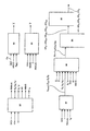
図1から図3において、車両1は、4つの車輪、すなわち左前輪A、右前輪B、右後輪C、左後輪D上に取り付けられた車体2を含む。
1 to 3, a
各車輪A、B、C、Dは、その独自のストッパ間ばねサスペンションRシステムSによって車体2に連結されるが、これはハイドロニューマチックサスペンションとすることもできる。
Each wheel A, B, C, D is connected to the
各サスペンションシステムSは、オンボードコンピュータCSSによって制御されるアクチュエータMを具備するショックアブソーバAMを含む。 Each suspension system S includes a shock absorber AM having an actuator M controlled by an on-board computer CSS.
このアクチュエータMはたとえば、ショックアブソーバAM内のオイルの通過断面積を変えることができるモータである。したがって、ショックアブソーバ内のオイルの各通過断面積に対し、ショックアブソーバとは異なる減衰則が対応する。この減衰則は、減衰状態とも呼ばれ、曲線、数値表、数式、その他の形態で記憶される。図15はこれらの減衰則ERを示しており、そこでは各減衰則は、ショックアブソーバAMの変位速度VDEBに応じてこのショックアブソーバから車体側に加えられる力の所定の曲線であり、変位速度が一定であるとすると、法則がきついほど、力が大きくなる。減衰状態ERは、減衰状態がよりきつくなる、すなわち一定の変位速度VDEBのとき減衰力が大きくなる順に番号が付与される。したがって最小の減衰状態は、最小のきつさを有する、すなわち各変位速度VDEBに対する最小値以上の減衰力に対応する減衰状態に相当する。 The actuator M is, for example, a motor that can change the passage cross-sectional area of oil in the shock absorber AM. Therefore, an attenuation law different from that of the shock absorber corresponds to each cross-sectional area of the oil in the shock absorber. This attenuation law is also called an attenuation state, and is stored in a curve, a numerical table, a mathematical expression, or other forms. FIG. 15 shows these damping laws ER, in which each damping law is a predetermined curve of the force applied from the shock absorber to the vehicle body according to the displacement speed VDEB of the shock absorber AM. If it is constant, the stronger the law, the greater the force. The damping state ER is assigned a number in order of increasing damping force when the damping state becomes tighter, that is, at a constant displacement speed VDEB. Therefore, the minimum damping state corresponds to a damping state having a minimum tightness, that is, corresponding to a damping force equal to or greater than the minimum value for each displacement speed VDEB.
有用な信号(車両速度、ABS制御、制動システムから供給される横方向加速度および縦方向加速度、ユーザーとのインタフェース(インテリジェントサーボ制御ボックス)から供給される運転者が要求するスポーツ性など)の大部分を回収するためにコンピュータCSSが車両のネットワークCANに接続される。またコンピュータは、各瞬間の車の動きを知るために自前のセンサを使用する(センサと直接電線で接続する)。さらにコンピュータは、自身が制御を行うアクチュエータにも接続される。 Most of useful signals such as vehicle speed, ABS control, lateral and longitudinal acceleration supplied by braking system, sport required by driver supplied from user interface (intelligent servo control box), etc. Computer CSS is connected to the vehicle network CAN. In addition, the computer uses its own sensor to know the movement of the car at each moment (connected directly to the sensor with an electric wire). The computer is also connected to an actuator that it controls.
モータは、ショックアブソーバAMが一定数Nの離散減衰則を有するステッピングモータとするか、ショックアブソーバAMが無限の減衰則を有する位置サーボ制御直流モータとすることができる。 The motor can be a stepping motor in which the shock absorber AM has a constant number N of discrete damping laws, or a position servo controlled DC motor in which the shock absorber AM has an infinite damping law.
たとえばステッピングモータ方式アクチュエータは9つの異なる安定位置をとることができ、それにより、ソフトからハードまで9つの減衰則を得ることができる。実際、オイルの通過断面積が小さいほど、減衰抗力は大きくなり、減衰はハードになる。 For example, a stepping motor actuator can take nine different stable positions, thereby obtaining nine damping laws from soft to hard. In fact, the smaller the oil cross section, the greater the damping drag and the harder the damping.
安定な則も不安定な則も存在し得る。安定な則の場合、ステッピングモータがその角度設定値を見い出すようステッピングモータを制御するだけでよい。安定な則のアクチュエータは、制御が終了すれば、たとえ電源が供給されなくなってもこの位置に留まる。反対に、不安定な則の場合、モータはこの則内に留まるためには、電源が供給されたままの状態に維持しなければならない。たとえば、一実施形態においては、安定な則と不安定な則の双方があり、不安定な則はたとえば連続する2つの安定な則の間に位置する。たとえば図15では安定な則が9個、不安定な則が8個ある。別の実施形態では、たとえば16個など、全ての則が安定である。 There can be both stable and unstable laws. In the case of a stable law, it is only necessary to control the stepping motor so that the stepping motor finds its angle setting value. The stable law actuator will remain in this position once control is terminated, even if power is not supplied. Conversely, in the case of an unstable law, the motor must remain powered in order to stay within this law. For example, in one embodiment, there are both a stable law and an unstable law, and the unstable law is located, for example, between two consecutive stable laws. For example, in FIG. 15, there are nine stable rules and eight unstable rules. In another embodiment, all rules are stable, such as 16, for example.
各アクチュエータMは、アクチュエータMの複数の位置のうちから1つの位置を選択して、この位置に対応する所定の減衰則を課す、制御量ERをコンピュータCSSから受け取るために、このコンピュータに接続された制御入力部COMを有する。 Each actuator M is connected to this computer in order to receive a controlled variable ER from the computer CSS, selecting one of the positions of the actuator M and imposing a predetermined damping law corresponding to this position. And a control input unit COM.
本発明によれば、車両の車輪A、B、C、Dのうちの少なくとも1つ上、好ましくは各車輪A、B、C、D上に変位センサCAP−DEBが設けられる。したがって各センサCAP−DEBは、車体2に対する車輪の変位DEBを測定する。
According to the invention, a displacement sensor CAP-DEB is provided on at least one of the wheels A, B, C, D of the vehicle, preferably on each wheel A, B, C, D. Accordingly, each sensor CAP-DEB measures the wheel displacement DEB relative to the
車輪変位センサCAP−DEBはたとえば角度によるものであり、車輪の回転軸と車体2との間の角度の瞬間値を示す。たとえば図1から図18では、各変位センサCAP−DEBは、車体2に固定されたたとえばハウジングのような固定部分CAPFと、車輪に固定された要素に結合された可動部分CAPMとを含む。コネクティングロッドBIELは可動部分CAPMを固定部分CAPFに連結し、車体2に対して車輪が上昇または下降するとき、固定部分CAPFに含まれる角度測定装置MESを回転させる。可動部分CAPMはたとえば車輪の回転軸AXの支持要素SUP上に固定される。この支持要素SUPは車体2に対してほぼ縦方向の軸SUPL周りで可動である。可動要素CAPMは回転軸SUPLから距離をおいたところにある支持要素SUP上に固定される。
The wheel displacement sensor CAP-DEB is based on an angle, for example, and indicates an instantaneous value of the angle between the wheel rotation shaft and the
車輪A、B、C、Dの変位の測定値DEBは、センサCAP−DEBから、対応する入力部E−DEBを含むコンピュータCSSに送られる。 The measured values DEB of the displacements of the wheels A, B, C, D are sent from the sensor CAP-DEB to the computer CSS including the corresponding input part E-DEB.
モーダル加速度
コンピュータCSSは、車輪の変位の測定値DEBを基にして、車体のポンピング時のモーダル加速度

![]()
![]()
FA、FB、FC、FDは、車輪A、B、C、DからそれらのサスペンションSを介して車体2にそれぞれ加えられる力であり、
νは車体2のトレッド、すなわち右輪と左輪との間の横方向における距離であり、
eは車両のホイールベースであり、
lgは重心Gと前輪AおよびBの横方向軸の間の長手方向における距離であり、
Mは、車両に乗客がいない場合の車体2の所定の質量であり、
Iθはロール時の慣性モーメントであり、Iφはピッチ時の慣性モーメントであり、
CBADは、アンチロールバーBADから車体2に加えられるトルクであり、
Cθはロールトルクであり、Cφはピッチトルクである)
FA, FB, FC, and FD are forces applied to the
ν is the tread of the
e is the wheelbase of the vehicle,
lg is the distance in the longitudinal direction between the center of gravity G and the lateral axis of the front wheels A and B;
M is a predetermined mass of the
I θ is the moment of inertia at the roll, I φ is the moment of inertia at the pitch,
CBAD is a torque applied to the
(C θ is roll torque, and C φ is pitch torque)
以下、本発明による制御方法を使用する種々の計算手段について説明する。 Hereinafter, various calculation means using the control method according to the present invention will be described.
コンピュータCSS内のモーダル加速度の計算方法はたとえば図4および図5に示すモジュール10が使用する。
For example, the
図に示すモジュラーブロックは、任意の適当な自動手段、特にソフトウェアによってコンピュータCSS内で使用される。 The modular block shown in the figure is used in the computer CSS by any suitable automatic means, in particular software.
モジュール10は、車輪の変位の測定値DEBを入力部で受け取って、モーダル加速度
手段CALは、
− アンチロールバーBADによって発生するトルクCBADの推定器11と、
− 各車輪A、B、C、Dから車体2に加えられる力FA、FB、FC、FDの推定器12と、
− 手段CALの入力部に供給される変位の測定値DEBのフィルタ13と
を含む。
The means CAL
An
An
A displacement measurement value DEB filter 13 supplied to the input of the means CAL.
フィルタ13は、センサCAP−DEBから供給される変位の測定値DEBの低周波を除去する。 The filter 13 removes the low frequency of the displacement measurement value DEB supplied from the sensor CAP-DEB.
このフィルタ13は、たとえば、0.2Hz以上の低域遮断周波数を有する高域フィルタを含む。したがってフィルタ13は、たとえば、通過帯域において充分に一定の位相を保持することができる、たとえば8Hz以上の高域遮断周波数をさらに有する帯域フィルタで作製される。 The filter 13 includes a high-pass filter having a low-frequency cutoff frequency of 0.2 Hz or higher, for example. Therefore, the filter 13 is made of, for example, a band-pass filter that can maintain a sufficiently constant phase in the pass band, and further has a high cut-off frequency of, for example, 8 Hz or more.
車輪の変位の測定値DEBを基にしてフィルタ13の出力部に供給されるろ波された車輪の変位DEBFは、推定器11の入力部ならびに推定器12の別の入力部に送られる。フィルタ13は、センサCAP−DEBからそれぞれの車輪A、B、C、Dに供給される4つの変位測定値DEB(A)、DEB(B)、DEB(C)、DEB(D)を基にして、4つのろ波された変位測定値DEBF(A)、DEBF(B)、DEBF(C)、DEBF(D)を供給する。
The filtered wheel displacement DEBF supplied to the output of the filter 13 based on the measured wheel displacement DEB is sent to the input of the
アンチロールバー
推定器11は、アンチロールバーのトルクCBADを、フィルタ13から供給されるろ波された変位の値DEBFの関数として以下のように計算する:
− 左前輪の場合:
CBAD(A)=(DEBF(A)−DEBF(B)).(Kbadav)/v2、
− 右前輪の場合:
CBAD(B)=−CBAD(A)
− 左後輪の場合:
CBAD(D)=(DEBF(D)−DEBF(C)).(Kbadar)/v2、
− 右後輪の場合:
CBAD(C)=−CBAD(D)
(式中、Kbadavは、フロントアンチロールバーBADの剛性に対応する所定のパラメータであり、
Kbadarは、図示しないリアアンチロールバーの剛性に対応する所定のパラメータである)
The
− For the front left wheel:
C BAD (A) = (DEBF (A) −DEBF (B)). (Kbadav) / v 2 ,
− For the front right wheel:
C BAD (B) = − C BAD (A)
-For the left rear wheel:
C BAD (D) = (DEBF (D) −DEBF (C)). (Kbadar) / v 2 ,
− For the right rear wheel:
C BAD (C) = − C BAD (D)
(Where Kbadav is a predetermined parameter corresponding to the rigidity of the front anti-roll bar BAD,
Kbadar is a predetermined parameter corresponding to the rigidity of a rear anti-roll bar (not shown))
サスペンションの抗力
サスペンションの抗力の推定器12は、ろ波された変位DEBFのための入力部、非ろ波変位DEBのための入力部、アクチュエータの実状態ER、すなわちアクチュエータが現在使用している減衰則ERのための入力部であってこの実状態およびその変化がたとえば記憶される入力部、前輪への静的抗力の入力部DEAV、および後輪への静的抗力の入力部DEARを含む。
Suspension drag
次に、左前輪Aへのサスペンションの抗力FAを計算するために、例として、図5においてこの推定器12について説明する。もちろん、他の抗力FB,FC、FDについても計算は同様であり、専ら車輪Aのみに関する値を車輪B、CまたはDに対応する値に置き換えることによって行われる。
Next, in order to calculate the drag FA of the suspension to the left front wheel A, the
推定器12内では、車輪A上のセンサCAP−DEBによって測定された変位DEB(A)が、変位DEB(A)の通過帯域を制限する低域フィルタPBに送られ、このフィルタに続いて、車輪Aに関する変位速度VDEBを得るための微分モジュールDERがある。車輪の変位速度VDEBは推定器12およびモジュール10の出力部に供給される。
Within the
ショックアブソーバAMによって車体2に加えられる減衰力FAMの計算モジュールMFAMは、当該車輪の実状態ERおよび変位速度VDEBを入力部において受け取る。ショックアブソーバAMの減衰則はたとえば事前に記憶するか、状態ERが指定された時点で再計算することができる。各減衰則ERにより、変位速度VDEBを、ショックアブソーバAMによって加えられる減衰力FAMの関数として計算または決定することが可能となり、逆も可能である。モジュールMFAMは、状態ERを基にして車輪AのショックアブソーバAMに対する現在有効な減衰則を求め、たとえば、則の曲線の読み取りによって、選択されたこの則に関する車輪Aの変位速度VDEB(A)から、車輪Aの減衰力FAMを求める。
The calculation module MFAM of the damping force FAM applied to the
車輪AのショックアブソーバAMの乾燥摩擦力FSECの別の計算モジュールMFSECは、車輪の変位速度VDEBも入力部で受け取り、次式により乾燥摩擦力FSECを計算する:
Fsec=(FsAv).tanh(VDEB/10−2)
(式中、VDEBの単位はcm/秒であり、FsAvは試験台で予め計算された前輪の乾燥摩擦係数であり、たとえばおよそ200ニュートンに等しい)
Another calculation module MFSEC of the dry friction force FSEC of the shock absorber AM of the wheel A also receives the wheel displacement speed VDEB at the input and calculates the dry friction force FSEC by the following formula:
Fsec = (FsAv). tanh (VDEB / 10 -2 )
(Where VDEB is in cm / second and FsAv is the front wheel dry friction coefficient pre-calculated on the test bench, eg, equal to approximately 200 Newtons)
この摩擦係数は、後輪に関する摩擦係数FsArで置き換えられる。 This friction coefficient is replaced with the friction coefficient FsAr for the rear wheel.
静的特性の推定器
静的姿勢ASの計算モジュールMASは、4輪A、B、C、Dの変位DEBを入力部で受け取り、これらの変位から、水平な地面上に車両が停止しているときのサスペンションの静的安定位置Sを表す静的姿勢ASを計算する。このモジュールMASはフロント静的姿勢ASavおよびリア静的姿勢ASarを計算する。フロント静的姿勢ASavはたとえば、前輪A、Bの変位DEBの平均変位DEBAVMOY(ハーフサム)を、たとえば二次Butterworthタイプの低域フィルタでろ波したものと計算され、次いで、このろ波平均変位にフロント姿勢の偏移定数が付加される。リア静的姿勢ASarはたとえば、後輪C、Dの変位DEBの平均変位DEBARMOY(ハーフサム)を、たとえば二次Butterworthタイプの低域フィルタでろ波したものと計算され、次いで、このろ波平均変位にフロント姿勢の偏移定数が付加される。リア静的姿勢ASarはたとえば、後輪C、Dの変位DEBの平均変位DEBARMOY(ハーフサム)を、たとえば二次Butterworthタイプのローパスフィルタでろ波したものと計算され、次に、このろ波平均変位にリア姿勢のシフト定数が付加される。変位センサCAP−DEBはこの静的姿勢ASを基準とする変位を測定するように較正されているものと仮定する。加算器AD1は車輪Aのろ波済み変位DEBF−Aを車輪Aについて計算された静的ASすなわちフロント静的姿勢に加算して、車輪Aに対するばねRの実長を得る。
Static characteristic estimator The calculation module MAS for the static attitude AS receives the displacement DEB of the four wheels A, B, C, D at the input unit, and from these displacements, the vehicle is stopped on the horizontal ground. A static posture AS representing the static stable position S of the suspension at that time is calculated. This module MAS calculates the front static attitude ASaav and the rear static attitude ASaar. The front static posture ASav is calculated, for example, by filtering the average displacement DEBAVMOY (half-sum) of the displacement DEB of the front wheels A and B with, for example, a second-order Butterworth type low-pass filter. An attitude shift constant is added. The rear static posture ASa is calculated, for example, by filtering the average displacement DEBARMOY (half-sum) of the displacement DEB of the rear wheels C and D with, for example, a second-order Butterworth type low-pass filter. A shift constant of the front posture is added. The rear static attitude ASa is calculated, for example, by filtering the average displacement DEBARMOY (half-sum) of the displacement DEB of the rear wheels C and D with, for example, a second-order Butterworth type low-pass filter. A rear attitude shift constant is added. It is assumed that the displacement sensor CAP-DEB is calibrated to measure the displacement with reference to this static attitude AS. The adder AD1 adds the filtered displacement DEBF-A of the wheel A to the static AS calculated for the wheel A, that is, the front static attitude, to obtain the actual length of the spring R with respect to the wheel A.
静的姿勢ASの計算モジュールMASはたとえば、4輪A、B、C、Dの変位DEB、ハイドロニューマチックサスペンションの場合のフロント静的圧力およびリア静的圧力、車両速度VVH、開口部情報IOを入力部で受け取る、図6に示すような静的特性推定器20の一部を成す。車両速度VVHは、たとえば速度センサあるいはその他の任意の計算手段から供給される。
The calculation module MAS for the static attitude AS includes, for example, the displacement DEB of the four wheels A, B, C and D, the front static pressure and the rear static pressure in the case of the hydropneumatic suspension, the vehicle speed VVH, and the opening information IO. It forms part of a static
静的特性推定器20は、
− 変位DEBの関数としてフロントみかけ動的質量MDAAVおよびリアみかけ動的質量MDAARを計算する手段と、
− 車両速度VVHの関数としてフロント空力バイアスBAAVおよびリア空力バイアスBAARを計算する手段と、
− フロントみかけ動的質量MDAAVおよびリアみかけ動的質量MDAARならびにフロント空力バイアスBAAVおよびリア空力バイアスBAARの関数として車両のばね上重量MSUSならびに車両のフロントとリアの間の重量配分値RMAvArを計算する手段と、
− ばね上重量MSUSおよびリアばね上重量MSUSARの関数としてロール時の慣性モーメントIθおよびピッチ時の慣性モーメントIφを計算する手段と、
− 重心Gと前輪A、Bの軸との間の長さlgを計算する手段と、
− 静的姿勢ASおよびフロントとリアとの間の重量配分値RMAvArの関数としてポンピング時のモーダルばね定数kz、ピッチ時のモーダルばね定数kφ、およびロール時のモーダルばね定数kθを計算する手段と
を含む。
The static
Means for calculating the front apparent dynamic mass MDAAV and the rear apparent dynamic mass MDAAR as a function of the displacement DEB;
Means for calculating a front aerodynamic bias BAAV and a rear aerodynamic bias BAAR as a function of the vehicle speed VVH;
Means for calculating the vehicle sprung mass MSUS and the vehicle front-to-rear weight distribution value RMAvAr as a function of the front apparent dynamic mass MDAAV and the rear apparent dynamic mass MDAAR and the front aerodynamic bias BAAV and the rear aerodynamic bias BAAR When,
Means for calculating the moment of inertia I θ at roll and the moment of inertia I φ at pitch as a function of the sprung weight MSUS and the rear sprung weight MSUSAR;
-Means for calculating a length lg between the center of gravity G and the axes of the front wheels A, B;
-Calculate the modal spring constant k z during pumping, the modal spring constant k φ during pitch, and the modal spring constant k θ during roll as a function of the static attitude AS and the weight distribution value RMAvAr between the front and rear. Means.
フロントみかけ動的質量MDAAVは、
− 前輪A、Bの変位DEBの平均変位(ハーフサム)に等しいフロント相対変位を計算し、次にフロント変位定数を加え、
− フロント相対変位の関数としてフロントばね動的たわみ抗力EDFAVを与える登録された表または曲線からこの抗力EDFAVを抽出し、
− 式
MDAAV=(EDFAV.2/g)+フロント定数
(式中、gは重力加速度=9.81m.s−2である)によってフロントみかけ動的質量MDAAVを計算する
ことによって計算される。
Front apparent dynamic mass MDAAV is
-Calculate the front relative displacement equal to the average displacement (half sum) of the displacement DEB of the front wheels A, B, then add the front displacement constant,
-Extracting this drag EDFAV from a registered table or curve giving the front spring dynamic deflection drag EDFAV as a function of the front relative displacement;
Calculated by calculating the front apparent dynamic mass MDAAV with the formula MDAAV = (EDFAV.2 / g) + front constant, where g is gravitational acceleration = 9.81 m · s −2 .
リアみかけ動的質量MDAARは、
− 後輪C、Dの変位DEBの平均変位量(ハーフサム)に等しいリア相対変位を計算し、次にリア変位定数を加え、
− リア相対変位の関数としてリアばね動的たわみ抗力EDFARを与える登録された表または曲線からこの抗力EDFARを抽出し、
− 式
MDAAR=(EDFAR.2/g)+リア定数
によってリアみかけ動的質量MDAARを計算する
ことによって計算される。
Rear apparent dynamic mass MDAAR is
-Calculate the rear relative displacement equal to the average displacement (half sum) of the displacement DEB of the rear wheels C, D, then add the rear displacement constant,
-Extracting this drag EDFAR from a registered table or curve giving the rear spring dynamic deflection drag EDFAR as a function of the rear relative displacement;
-Calculated by calculating the rear apparent dynamic mass MDAAR by the formula MDAAR = (EDFAR.2 / g) + rear constant.
ばね動的たわみ抗力はその静的位置に対応するばねの平衡位置においては0であり、フロント相対変位は静的平衡位置を基準とする変位であり、抽出はたとえば表の補間によって行われるが、EDFAV、EDFARの登録された曲線を基にして行うこともできる。 The spring dynamic deflection drag is zero at the spring equilibrium position corresponding to its static position, the front relative displacement is the displacement relative to the static equilibrium position, and the extraction is performed, for example, by table interpolation, It can also be performed based on registered curves of EDFAV and EDFAR.
ハイドロニューマチックサスペンションの場合、フロント静的圧力およびリア静的圧力を用いて質量MDAARおよび質量MDAAVが計算される。 For hydropneumatic suspensions, the mass MDAAR and mass MDAAV are calculated using the front static pressure and the rear static pressure.
kgを単位とする質量において均一なフロント空力バイアスBAAVは、式
BAAV=(CAV.VVH2)/g
によって計算される。
(式中、CAVはフロントの所定の空力係数である)
Uniform front aerodynamic bias BAAV in mass in kg is given by the formula BAAV = (CAV.VVH 2 ) / g
Calculated by
(Where CAV is the predetermined aerodynamic coefficient of the front)
kgを単位とする質量において均一なリア空力バイアスBAARは、式
BAAR=(CAR.VVH2)/g
によって計算される。
(式中、CARはリアの所定の空力係数である)
A uniform rear aerodynamic bias BAAR in mass in kg is given by the formula BAAR = (CAR.VVH 2 ) / g
Calculated by
(Where CAR is the predetermined rear aerodynamic coefficient)
車両のばね上重量MSUSおよび重量配分値RMAvArの計算
まず、フロントアクスルのばね上重量MSUSEAVを計算する。これを行うには、図7および図8に示すように、ステップS1で、合計(フロントみかけ動的質量MDAAV+フロント空力バイアスBAAV)を低域フィルタPB1によってろ波し、ろ波されたフロントアクスルのばね上重量MSUSEAVFを得る。
Calculation of vehicle sprung mass MSUS and weight distribution value RMAvAr First, the front axle sprung mass MUSEAV is calculated. To do this, as shown in FIGS. 7 and 8, in step S1, the total (front apparent dynamic mass MDAAV + front aerodynamic bias BAAV) is filtered by the low-pass filter PB1, and the filtered front axle is filtered. Obtain the sprung weight MSUSEAVF.
次に、
− ステップS2で、車両速度VVHが所定の下側しきい値VVH1と上側しきい値VVH2との間にあるかどうかを確認し、
− ステップS3で、開口部情報IOが「閉」であるか、あるいは車両速度VVHが規定のしきい値VVH3より大きいかどうかを確認し、
− ステップS4で、ろ波されたフロントアクスルのばね上重量MSUSEAVF(n)とその前にメモリに登録されたその値MSUSEAVF(n−1)との差が充分である(絶対値で規定の差Δより大きい)かどうかを確認する。
next,
In step S2, check whether the vehicle speed VVH is between a predetermined lower threshold value VVH1 and an upper threshold value VVH2,
-In step S3, check whether the opening information IO is "closed" or whether the vehicle speed VVH is greater than a prescribed threshold value VVH3;
The difference between the sprung mass MSUSEAVF (n) of the filtered front axle and its value MSUSEAVF (n−1) previously registered in the memory is sufficient (in absolute value, the specified difference) Whether it is greater than Δ).
これらの条件が実現される場合、フロントアクスルのばね上重量MSUSEAVはろ波済みフロントアクスルばね上重量MSUSEAVFに等しいとされ、ステップS5でメモリMEM内ならびに図7に示すソフトウェアスイッチCOMLOGの位置に登録される。 If these conditions are fulfilled, the front axle sprung mass MSUSEAV is assumed to be equal to the filtered front axle sprung mass MSUSEAVF and is registered in the memory MEM and in the position of the software switch COMLOG shown in FIG. 7 in step S5. .
これらの条件のうちの1つ、複数、あるいは全てが実現しない場合、フロントアクスルのばね上重量MSUSEAV(n)は変化せず、直前のステップS6でメモリMEM内ならびにソフトウェアスイッチCOMLOGの他の位置に登録されたMSUSEAV(n−1)の値に等しいままである。 If one, more or all of these conditions are not fulfilled, the sprung mass MSUSEAV (n) of the front axle does not change, and in the immediately preceding step S6, in the memory MEM and other positions of the software switch COMLOG. It remains equal to the registered MSUSEAV (n-1) value.
次に、ステップS7で、フロントアクスルのばね上重量MSUSEAVを低域フィルタPB2によってろ波し、場合によっては、このろ波により上側しきい値より上、および下側しきい値より下で得られた値を飽和させることにより、フロントばね上重量MSUSAVを計算する。 Next, in step S7, the front axle sprung mass MSUSEAV is filtered by the low pass filter PB2, and in some cases this filtering is obtained above the upper threshold and below the lower threshold. The front sprung mass MSUSAV is calculated by saturating the value.
低域フィルタPB1およびPB2は、たとえばそれぞれが0.02Hzの遮断周波数を有する一次フィルタである。 The low-pass filters PB1 and PB2 are primary filters each having a cutoff frequency of 0.02 Hz, for example.
リアアクスルのばね上重量MSUSEARおよびリアばね上重量のMSUSARを計算する場合も、作業の進行は同様であるが、MDAAV+BAAVをMDAAR+BAARで置き換え、MSUSEAVFをMSUSEARFで置き換えて行う。 When calculating the rear axle sprung mass MSUSEAR and the rear sprung mass MSUSAR, the process proceeds in the same manner, except that MDAAV + BAAV is replaced with MDAAR + BAAR, and MSUSEAVF is replaced with MSUSEARF.
次に、フロントばね上重量MSUSAVおよびリアばね上重量MSUSARの合計を求めることにより、車両のばね上重量MSUSが計算される。
MSUS=MSUSAV+MSUSAR
Next, the vehicle sprung weight MSUS is calculated by determining the sum of the front sprung weight MSUSAV and the rear sprung weight MSUSAV.
MSUS = MSUSAV + MUSASAR
次に、フロントばね上重量MSUSAVを車両のばね上重量MSUSで割ることにより、フロント−リア重量配分値RMAvArが計算される。
RMAvAr=MSUSAV/MSUS
Next, a front-rear weight distribution value RMAvAr is calculated by dividing the front sprung weight MUSASV by the vehicle sprung weight MSUSAV.
RMAvAr = MSUSAV / MSUS
慣性モーメントの計算
ロール時の慣性モーメントIθは、次式によりリアばね上重量MSUSARの関数として計算される。
Iθ=Ay.MSUSAR+By
ただし、MSUSAR=(1−RMAvAr).MSUS
(式中、AyおよびByは所定のパラメータである)
Calculation of moment of inertia The moment of inertia I θ during the roll is calculated as a function of the rear sprung mass MSUSAR by the following equation.
I θ = A y . MSUSAR + B y
However, MSUSAR = (1-RMAvAr). MSUS
(Wherein, A y and B y are predetermined parameters)
ピッチ時の慣性モーメントIφは、次式によりばね上重量MSUSの関数として計算される。
Iφ=Ax.MSUS+Bx
(式中、AxおよびBxは所定のパラメータである)
The moment of inertia I φ at the time of pitch is calculated as a function of the sprung weight MSUS by the following equation.
I φ = A x . MSUS + B x
(Where A x and B x are predetermined parameters)
長さlgおよびモーダルばね定数の計算
フロントサスペンションばね定数kAVおよびリアサスペンション定数kARを計算する。
Calculation of length lg and modal spring constant The front suspension spring constant kAV and the rear suspension constant kAR are calculated.
フロントサスペンションばね定数kAVは、フロントサスペンションのばね定数をフロント静的姿勢ASavの関数として与える所定の表または曲線から、たとえば線形補間により、フロント静的姿勢ASavに対応するフロントばね定数値を差し引くことによって得られる。 The front suspension spring constant kAV is obtained by subtracting the front spring constant value corresponding to the front static attitude Asav from, for example, linear interpolation from a predetermined table or curve that gives the spring constant of the front suspension as a function of the front static attitude ASav. can get.
リアサスペンションばね定数kARは、リアサスペンションのばね定数をリア静的姿勢の関数として与える所定の表または曲線から、たとえば線形補間により、リア静的姿勢ASarに対応するリアばね定数値を差し引くことによって得られる。 The rear suspension spring constant kAR is obtained by subtracting the rear spring constant value corresponding to the rear static attitude ASa from a predetermined table or curve that gives the spring constant of the rear suspension as a function of the rear static attitude, for example, by linear interpolation. It is done.
長さlgは次式によって計算される:
lg=(1−RMAvAr).e
The length lg is calculated by the following formula:
lg = (1-RMAvAr). e
図4のモジュールCGIはこの長さlgの計算を使用し、たとえば推定器20の一部を成す。
The module CGI of FIG. 4 uses this length lg calculation and forms part of the
ポンピング時のモーダルばね定数kzは、フロントサスペンションばね定数kAVとリアサスペンションばね定数kARの合計として計算される。
kz=kAV+kAR
The modal spring constant k z at the time of pumping is calculated as the sum of the front suspension spring constant kAV and the rear suspension spring constant kAR.
k z = kAV + kAR
ピッチ時のモーダルばね定数kφは次式により計算される
kφ=kAV.(lg)2+kAR(e−lg)2
The modal spring constant kφ at the time of pitch is calculated by the following equation: k φ = kAV. (Lg) 2 + kAR (e-lg) 2
ローリング時のモーダルばね定数kθは次式により計算される
kθ=kbadav+kbadar+v2.(kAV+kAR)/4
The modal spring constant k θ at the time of rolling is calculated by the following equation: k θ = kbadav + kbadar + v 2 . (KAV + kAR) / 4
車体のモーダル加速度の計算
図5でモジュールMLRは、たわみ力をばねRの長さの関数として与える登録された表または曲線を基にして、この長さの実入力値LRに対応する絶対たわみ力FLEX−ABSを計算する。この登録されたたわみの曲線は、たとえばゴム製であって、ばねがショックアブソーバAMのストローク端でサスペンションストップにてこれらのストップを押圧したとき、より大きな抗力を車体に加えるバンプストップも考慮に入れる。
Calculation of the modal acceleration of the vehicle body In FIG. 5, the module MLR calculates the absolute deflection force corresponding to the actual input value LR of this length, based on a registered table or curve that gives the deflection force as a function of the length of the spring R. Calculate FLEX-ABS. This registered deflection curve is made of, for example, rubber, and takes into account the bump stop that adds more drag to the car body when the springs press these stops at the suspension stop at the stroke end of the shock absorber AM. .
さらに、モジュールMDEAは静的姿勢ASを入力部で受け取り、この姿勢の関数として、前輪への対応する静的たわみ抗力DEAV、ならびに後輪への対応する静的たわみ抗力DEARを計算する。 Further, the module MDEA receives the static attitude AS at the input unit, and calculates the corresponding static deflection resistance DEAV to the front wheels and the corresponding static deflection resistance DEAR to the rear wheels as a function of this attitude.
減算器SOUSは、計算された絶対たわみ力FLEX−ABSから、静的抗力DEAVまたはDEAR、たとえば前輪Aの場合は抗力DEAVを減算して、スプリングRおよびエンドストッパによって車体2に加えられる力に対応するばねおよびバンプエンドのたわみ力FLBを得る。
The subtractor SOUS subtracts the static drag DEAV or DEAR, for example, the drag DEAV in the case of the front wheel A, from the calculated absolute deflection force FLEX-ABS, and corresponds to the force applied to the
加算器AD2は、減衰力FAM、乾燥摩擦力FSECならびにスプリングおよびバンプエンドのたわみFLBを加算し、次式によって力FAを得る。
FA=FAM+FSEC+FLB
The adder AD2 adds the damping force FAM, the dry friction force FSEC, and the spring and bump end deflection FLB, and obtains the force FA by the following equation.
FA = FAM + FSEC + FLB
モジュールCAL−ACCは、モジュール11によって計算されたトルクCBAD、推定器12によって計算されたサスペンション力FA、FB、FC、FD、ならびに車体質量M、ロール時の慣性モーメントIθ、およびピッチ時の慣性モーメントIφを入力部で受け取る。これらは、トルクCθおよびCφの影響を無視する、すなわちある実施形態においてCθ=0かつCφ=0とすることにより、モーダル加速度
下記の改良形態では、モーダル加速度の計算においてトルクCθおよびCφも考慮する。 In the refinement described below, torques Cθ and Cφ are also taken into account in the calculation of modal acceleration.
慣性量計算モジュールCGIは、M、Iθ、Iφならびに車両のフロントとリアの間の重量配分の入力値RMAvArの関数として、たとえば、67kgの人間4人が車両の居住空間内におり28kgの荷物が後部荷室内にあるような車両の標準荷重を考慮に入れた総重量MTOT=MREF、およびモジュールCAL−ACCに入力される、重心Gと前輪A、Bの軸との間の長さlgを計算する。重量配分値RMAvArは、変位センサCAP−DEBから供給される変位DEBを用い、変位DEBの計算平均値にこれらの各値を比較することによって推定される。 The inertial amount calculation module CGI is a function of M, I θ , I φ and the input value RMAvAr of the weight distribution between the front and rear of the vehicle. For example, four 67 kg persons are in the living space of the vehicle and 28 kg The total weight MTOT = MREF taking into account the standard load of the vehicle such that the load is in the rear luggage compartment, and the length lg between the center of gravity G and the front wheels A, B axis, which is input to the module CAL-ACC Calculate The weight distribution value RMAvAr is estimated by using the displacement DEB supplied from the displacement sensor CAP-DEB and comparing each of these values to the calculated average value of the displacement DEB.
総重量MTOTおよび横方向加速度ACCTの再設定値RECTも入力部で受け取るロールトルク推定器14に横方向加速度ACCTを供給するために、車両上に加速度計CAP−ACCTが設けられる。
An accelerometer CAP-ACCT is provided on the vehicle for supplying the lateral acceleration ACCT to the
横方向加速度計CAP−ACCTは、ロール中心CRではなく重心G上に位置する。横方向加速度の再設定値RECTは、モジュールCAL−ACCにより以下のように計算される:
nは現在のサイクルにおける変数の値を指し、(n−1)は1つ前のサイクルにおける変数の値を指す)
The lateral accelerometer CAP-ACCT is located on the center of gravity G, not the roll center CR. The lateral acceleration reset value RECT is calculated by the module CAL-ACC as follows:
n refers to the value of the variable in the current cycle, and (n-1) refers to the value of the variable in the previous cycle)
推定器14は、以下のようにロールトルクCθを計算する:
Cθ=(ACCT−RECT).(MTOT).d(G、CR)
(式中、d(G、CR)=HCdG−hRoulisは、重心Gとロール中心CRの間の距離であり、予め登録される)
The
C θ = (ACCT−RECT). (MTOT). d (G, CR)
(Where d (G, CR) = HCdG-hRoulis is the distance between the center of gravity G and the roll center CR and is registered in advance)
ピッチトルクCφの推定器15は、長さlg、総重量MTOT、車体内に配設された縦方向加速度計CAPLから供給される縦方向加速度ACCL、制動情報IF、およびモジュールCAL−ACCによって計算された縦方向加速度の再設定値RECLを入力部で受け取る。 Pitch torque C φ estimator 15 is calculated by length lg, total weight MTOT, longitudinal acceleration ACCL supplied from longitudinal accelerometer CAPL disposed in the vehicle body, braking information IF, and module CAL-ACC. The reset value RECL of the vertical acceleration thus received is received by the input unit.
縦方向加速度の再設定値RECLは、モジュールCAL−ACCにより以下のように計算される:
![]()
![]()
推定器15は、ピッチトルクCφを次式に従って計算する。
Cφ=(ACCL−RECL).(MTOT).hG+CφB
hG=HCdGは、ピッチ中心CTに対する重心Gの軸Z方向の高さであり、予め登録される。
The
C φ = (ACCL-RECL) . (MTOT). h G + C φB
h G = HCdG is the height in the axis Z direction of the center of gravity G with respect to the pitch center CT, and is registered in advance.
トルクCφの成分CφBは、Brouilhet効果によるピッチトルクの成分であり、制動情報IFの関数として計算される。決定モジュール16は、制動情報IFをマスターシリンダ圧PMCの値の関数として供給し、この値自体はブレーキのマスターシリンダ圧のセンサCAP−Pから供給される。
A component C φB of the torque C φ is a component of pitch torque due to the Bruilhet effect, and is calculated as a function of the braking information IF.
トルクCθおよびCφの計算値はモジュールCAL−ACCに入力され、このモジュールは、これらの値および他の入力値を基にして、ポンピング時のモーダル加速度
![]()
![]()
![]()
![]()
さらに、モジュール10の出力部SACCで提示されるこれら3つのモーダル加速度は、たとえば0.1Hz、0.2Hz、または0.3Hzの低域遮断周波数より下の低周波を除去するフィルタ17にそれぞれ送られる。フィルタ17はこの高域通過成分に加えて、たとえば低域通過成分を有し、その結果、帯域フィルタが形成される。フィルタ17の低域遮断周波数は、モーダル加速度
次に、フィルタ17の出力部においてろ波されたモーダル加速度は、高域フィルタを出力部に含む積分モジュール18に送られ、このモジュールは、車体のポンピング時のモーダル速度
これらの、ポンピング時
次にコンピュータCSSは、計算されたこれらのモーダル速度
「Skyhook」型制御
以下では、快適性すなわち「Skyhook」型ショックアブソーバの制御のための、ショックアブソーバの可変減衰モーダルゲインbmodおよび第1設定モーダル抗力Fmodについて説明する。
“Skyhook” Type Control In the following, the shock absorber variable damping modal gain b mod and the first set modal drag F mod for comfort, ie, the control of the “Skyhoe” type shock absorber, will be described.
このSkyhook型論理は、モジュール10によって生成される、ポンピング時
車体の運動レベルおよび車体の振動レベル
車輪の変位DEBの関数として車体の運動レベルNMCおよび車体の振動レベルNTCを計算するために推定器24が設けられる。
Body motion level and body vibration level An
図9において、車体の運動レベルNMCおよび車体の振動レベルNTCは、推定器24により、
− 前輪A、Bの変位の平均DEBAVMOYを計算し、
− 帯域フィルタPB3によりフロント変位の平均値DEBAVMOYをろ波し、ろ波量DEBAVMOYFを得、
− 再構築モジュールRED内で、ろ波量DEBAVMOYFの絶対値を取得し、再構築量|DEBAVMOYF|を得、
− 保持モジュールMMAX内で、車体の運動レベルNMCを示す再構築量|DEBAVMOYF|の最大値を保持する
ことによって得られる。
In FIG. 9, the motion level NMC of the vehicle body and the vibration level NTC of the vehicle body are obtained by the
-Calculate the average DEBAVMOY of the displacement of the front wheels A, B;
-The average value DEBAVMOY of the front displacement is filtered by the bandpass filter PB3 to obtain the filtered amount DEBAVMOYF;
-In the reconstruction module RED, obtain the absolute value of the filtering amount DEBAVMOYF, obtain the reconstruction amount | DEBAVMOYF |
In the holding module MMAX, obtained by holding the maximum value of the reconstruction amount | DEBAVMOYF | indicating the vehicle movement level NMC.
車体の運動レベルNMCを計算するには、帯域フィルタPB3は、比較的低い車体の振動周波数を通過させるように調節される。車体の運動の帯域フィルタPB3はたとえば0.5Hzから2.5Hzに調節されるのでサスペンションの共振周波数に近い。フィルタはたとえば、減衰運動レベルNMCおよび非減衰運動レベルNMCを得るための2つの勾配の間で選択することができる。 To calculate the vehicle body motion level NMC, the bandpass filter PB3 is adjusted to pass a relatively low vehicle body vibration frequency. The band filter PB3 of the vehicle body movement is adjusted from 0.5 Hz to 2.5 Hz, for example, so that it is close to the resonance frequency of the suspension. The filter can be selected, for example, between two slopes to obtain a damped motion level NMC and an undamped motion level NMC.
車体の振動レベルNTCを計算するには、帯域フィルタPB3は、比較的高い車体の運動周波数を通過させるように調節される。車体の振動の帯域フィルタPB3はたとえば3Hzの低域遮断周波数および8Hzまたはそれ以上の高域遮断周波数に調節される。フィルタはたとえば、減衰振動レベルNTCおよび非減衰振動レベルNTCを得るための2つの勾配の間で選択することができる。 To calculate the vehicle body vibration level NTC, the bandpass filter PB3 is adjusted to pass a relatively high body motion frequency. The band filter PB3 for body vibration is adjusted to a low cut-off frequency of 3 Hz and a high cut-off frequency of 8 Hz or higher, for example. The filter can be selected, for example, between two slopes to obtain a damped vibration level NTC and an undamped vibration level NTC.
保持モジュールMMAXは、パラメータ化可能な立ち下がり勾配とパラメータ化可能な最大値保持タイマをもつことができる。最大値保持タイマは、車体の振動レベルNTCを得る場合には、車体の運動レベルNMCを得る場合よりも短くなるよう選択する。 The holding module MMAX can have a parameterizable falling slope and a parameterizable maximum value holding timer. The maximum value holding timer is selected to be shorter when obtaining the vehicle vibration level NTC than when obtaining the vehicle movement level NMC.
Skyhook設定モーダル抗力およびモーダルゲイン
式Fmod=−bmod.Vmod.に従って、可変減衰のモーダルゲインbmodおよび減衰の第1設定モーダル抗力Fmodを計算するために推定器21が設けられる。
Skyhook setting modal drag and modal gain Formula F mod = −b mod . V mod . Accordingly, an
したがって、
− 第1ポンピングモーダル抗力
− 第1ロールモーダル抗力
− 第1ピッチモーダル抗力
がある。
Therefore,
-First pumping modal drag
-First roll modal drag
-1st pitch modal drag
There is.
モーダルゲインbz、bθ、bφは車輪A、B、C、Dの変位DEBの関数として可変であり、推定器21により、車輪A、B、C、Dのこれらの変位DEBの関数として前に計算された量の関数として計算される。
The modal gains b z , b θ and b φ are variable as a function of the displacement DEB of the wheels A, B, C and D, and are estimated by the
モーダルゲインbz、bθ、bφは、たとえば以下のような増倍係数を含めた単数または複数の増倍係数を含むことができる:
− それぞれポンピング時、ロール時、ピッチ時の基準増倍係数bzREF、bθREF、bφREF
− ポンピング時、ロール時、ピッチ時の減衰増倍係数bzATT、bθATT、bφATT
− ポンピング時、ロール時、ピッチ時の再設定増倍係数bzREC、bθREC、bφREC
− ポンピング時、ロール時、ピッチ時の運転タイプ増倍係数bzTYP、bθTYP、bφTYP
The modal gains b z , b θ , b φ can include one or more multiplication factors including, for example, the following multiplication factors:
− Reference multiplication factors b zREF , b θREF , b φREF for pumping, roll and pitch, respectively.
− Damping and multiplication factors b zATT , b θATT , b φATT during pumping, rolling and pitching
-Reset multiplication factors b zREC , b θREC , b φREC at the time of pumping, rolling, and pitching
- pumping time, roll up, multiplication operation type when pitch coefficient b zTYP, b θTYP, b φTYP
図6に示す実施形態においては、推定器21は以下の数値を入力部において受け取る:
− 推定器24から供給される車体運動レベルNMC
− 推定器24から供給される車体振動レベルNTC
− 車両速度VVH
− 推定器24から供給されるモーダルばね定数:ポンピング時モーダルばね定数kz、ロール時モーダルばね定数kθ、およびピッチ時モーダルばね定数kφ
− モジュール10から供給されるモーダル速度Vmod:車体ポンピング時モーダル速度
− 推定器20から供給されるばね上重量MSUS
− 運転者によりスポーツ運転位置またはスポーツ運転不在位置において車両のダッシュボードの対応するボタンが押されたのに応じて、スポーツ性不在ブール状態0または他のスポーツ性ブール状態1になることができるスポーツ性情報IS
In the embodiment shown in FIG. 6, the
The body motion level NMC supplied from the
-Body vibration level NTC supplied from the
-Vehicle speed VVH
-Modal spring constant supplied from the estimator 24: pumping modal spring constant k z , roll modal spring constant k θ , and pitch modal spring constant k φ
-Modal speed V mod supplied from the module 10: Modal speed at body pumping
The sprung weight MSUS supplied from the
A sport that can be in a sports absence
各モーダルゲインbz、bθ、bφについて、それぞれポンピング時、ロール時、ピッチ時の基準増倍係数bzREF、bθREF、bφREFは、基準増倍係数を車両速度の関数として与える予め登録された基準表または曲線から、たとえば直線補間により、車両の速度の入力値VVHに対応する基準増倍係数の値bzREF、bθREF、bφREFを抽出することによって得られる。 Each modal gains b z, b θ, b φ , respectively during pumping, roll up, the reference multiplier coefficient b ZREF during pitch, b .theta.ref, b .phi.REF is registered in advance to provide a reference multiplication factor as a function of vehicle speed The reference multiplication factor values b zREF , b θREF , and b φREF corresponding to the vehicle speed input value VVH are extracted from the obtained reference table or curve, for example, by linear interpolation.
各モーダルゲインbz、bθ、bφについて、それぞれポンピング時、ロール時、ピッチ時の減衰増倍係数bzATT、bθATT、bφATTは、
− 式
Rz=NTC−βz.NMC
Rθ=NTC−βθ.NMC
Rφ=NTC−βφ.NMC
(式中、βz、βθ、βφは、2つのレベルNMCおよびNTCの間の比を調節することが可能な予め登録されたパラメータであり、これらのパラメータβz、βθ、βφはたとえば0.5から1の間に調節される)に従って、
− 車体の運動レベルNMCおよび車体の振動レベルNTCの関数として、それぞれポンピング時、ロール時、ピッチ時の抵抗Rz、Rθ、Rφを計算し、
− 減衰増倍係数bzATT、bθATT、bφATTを、それぞれポンピング時、ロール時、ピッチ時の抵抗の関数として与える予め登録された表または曲線から、たとえば直線補間により、抵抗Rz、Rθ、Rφの計算値に対応する減衰増倍係数の値bzATT、bθATT、bφATTを抽出する
ことによって得られる。
For each of the modal gains b z , b θ , and b φ , attenuation multiplication factors b zATT , b θATT , and b φATT at the time of pumping, rolling, and pitch are
The formula R z = NTC-β z . NMC
Rθ = NTC− βθ . NMC
R φ = NTC−β φ . NMC
(Where β z , β θ , β φ are pre-registered parameters that can adjust the ratio between the two levels NMC and NTC, and these parameters β z , β θ , β φ Is adjusted between 0.5 and 1, for example)
-Calculating the resistances R z , R θ , R φ during pumping, rolling and pitch, respectively, as a function of the body motion level NMC and the body vibration level NTC;
- damping multiplication factor b zATT, b θATT, the b FaiATT, respectively during pumping, at a roll, from a table or curve is registered in advance given as a function of the resistance in the pitch, for example by linear interpolation, the resistance R z, R theta , R φ corresponding to the calculated values of the attenuation multiplication factors b zATT , b θATT , b φATT are obtained.
それぞれポンピング時、ロール時、ピッチ時の減衰増倍係数bzATT、bθATT、bφATTは、
− 式
bzATT=1/(1+az.Rz)
bθATT=1/(1+aθ.Rθ)
bφATT=1/(1+aφ.Rφ)
(式中、az、aθ、aφは予め登録されたパラメータである)
によって得られる。
The attenuation multiplication factors b zATT , b θATT , b φATT at the time of pumping, rolling, and pitch are respectively
The formula b zATT = 1 / (1 + a z .R z )
b θATT = 1 / (1 + a θ .R θ )
b φATT = 1 / (1 + a φ .R φ )
(In the formula, a z , a θ and a φ are parameters registered in advance)
Obtained by.
得られたbzATT、bθATT、bφATTの値は、たとえば、関係する抵抗Rz、Rθ、Rφが規定のしきい値より大きい場合にしか採用されない。関係する抵抗Rz、Rθ、Rφがこの規定のしきい値以下である場合、減衰増倍係数bzATT、bθATT、bφATTとして1が採用される。 The obtained values of b zATT , b θATT , b φATT are employed only when, for example, the related resistances R z , R θ , R φ are larger than a prescribed threshold value. If the related resistances R z , R θ , R φ are below this specified threshold, 1 is adopted as the attenuation multiplication factor b zATT , b θATT , b φATT .
各モーダルゲインbz、bθ、bφについて、それぞれポンピング時、ロール時、ピッチ時の再設定増倍係数bzREC、bθREC、bφRECは、
− 式
kθREFは、ロール時の基準ばね定数で、一定であり、
kφREFは、ピッチ時の基準ばね定数で、一定であり、
IθREFは、ロール時の基準慣性モーメントで、一定であり、
IφREFは、ピッチ時の基準慣性モーメントで、一定であり、
kzREF、kθREF、kφREF、MREF、IθREF、IφREFは、たとえば、67kgの人間4人が車両の居住空間内にあり28kgの荷物が後部荷室内にある、車両の標準荷重に対応する予め登録されたパラメータである)に従って得られる。
For each of the modal gains b z , b θ , b φ , reset multiplication factors b zREC , b θREC , b φREC at the time of pumping, rolling, and pitch are
− Expression
k θREF is a reference spring constant at the time of roll and is constant,
k φREF is the reference spring constant at the time of pitch and is constant,
I θREF is a reference moment of inertia at the time of roll and is constant,
I φREF is the reference moment of inertia at the time of pitch and is constant,
k z REF , k θ REF , k φ REF , M REF, I θ REF , I φ REF correspond to the standard load of the vehicle, for example, 4 people of 67 kg are in the vehicle's living space and 28 kg of luggage is in the rear luggage compartment Is a pre-registered parameter).
各モーダルゲインbz、bθ、bφについて、それぞれポンピング時、ロール時、ピッチ時の運転タイプの増倍係数bzTYP、bθTYP、bφTYPは、スポーツ性情報ISがスポーツ性ブール状態1にある場合には、予め登録されたスポーツ性のゲインGSz、GSθ、GSφに等しく、スポーツ性情報ISがスポーツ性不在ブール状態0にある場合には、1に等しい。
For each of the modal gains b z , b θ , b φ , the multiplication factors b zTYP , b θTYP , b φTYP of the driving type at the time of pumping, rolling, pitch, In some cases, it is equal to the pre-registered sports gains GS z , GS θ , GS φ , and is equal to 1 if the sports information IS is in the sports absence
モーダルゲインbz、bθ、bφは、式
bz=bzREF.bzATT.bzREC.bzTYP
bθ=bθREF.bθATT.bθREC.bθTYP
bφ=bφREF.bφATT.bφREC.bφTYP
によって、増倍係数の関数として計算される。
The modal gains b z , b θ , b φ are expressed by the equation b z = b zREF . b zATT . b zREC . b zTYP
b θ = b θ REF . b θATT . b θREC . b θTYP
b φ = b φREF . b φATT . b φREC . b φTYP
Is calculated as a function of the multiplication factor.
ポンピング第1モーダル抗力Fz1、ロール第1モーダル抗力Fθ1、ピッチ第1モーダル抗力Fφ1が計算されるが、これらは快適性すなわち「skyhook」モーダル抗力とも呼ばれる。ポンピング第1モーダル抗力Fz1、ロール第1モーダル抗力Fθ1、ピッチ第1モーダル抗力Fφ1は推定器21の出力部に供給される。
The pumping first modal drag F z1 , roll first modal drag F θ1 , pitch first modal drag F φ1 are calculated, which are also referred to as comfort or “skyhook” modal drag. The pumping first modal drag F z1 , the roll first modal drag F θ1 , and the pitch first modal drag F φ1 are supplied to the output unit of the
Roadhook論理
以下では、Roadhook型、すなわち道路プロフィールに従う論理について説明するが、この論理は、車体保持論理または挙動論理とも呼ばれる。
Roadhook logic In the following, a loadbook type, that is, a logic according to a road profile will be described. This logic is also called a vehicle body holding logic or a behavior logic.
この車体保持論理の原理は、車輪面に対する単数または複数の車体モーダル加速度、すなわちポンピング時のモーダル加速度、ロール時のモーダル加速度、ピッチ時のモーダル加速度を0に向かうようにするか最小化することである。 The principle of the vehicle body holding logic is that one or more vehicle body modal accelerations with respect to the wheel surface, that is, modal acceleration during pumping, modal acceleration during rolling, and modal acceleration during pitching are set to zero or minimized. is there.
図10において、装置は、車輪A、B、C、Dの測定変位DEBの関数としての車輪の平均面に対する車体のモーダル速度Vmod2の推定器31を含む。車輪の平均面に対する車体のこれらのモーダル速度Vmod2は相対速度と呼ばれ、ポンピング時の車体の相対モーダル速度
相対モーダル速度Vmod2のこの推定器31は以下のものを入力部で受け取る:
− 車輪A、B、C、D上で測定された変位DEB
− トレッドv
− フロントとリアの間の重量配分値RMAvAr、重心Gと前輪A、Bの軸の間の長さlg、ホイールベースeというパラメータのうちの少なくとも2つ
This
The displacement DEB measured on wheels A, B, C, D
-Tread v
The weight distribution value RMAvAr between the front and rear, the length lg between the center of gravity G and the front wheels A, B, the wheel base e, at least two of the following parameters:
変位DEBはまず、低周波変位のみを得て高周波振動の大部分は除去するように、たとえばButterworthタイプの二次低域フィルタによってろ波される。 The displacement DEB is first filtered by, for example, a Butterworth type secondary low pass filter so as to obtain only low frequency displacement and remove most of the high frequency vibration.
次に、車輪A、B、C、DのRoadhook変位速度を得るために、このようにろ波された変位DEBを微分器が微分する。 Next, in order to obtain the loadhook displacement speed of the wheels A, B, C, and D, the differentiator differentiates the displacement DEB thus filtered.
次に、次式に従って、相対モーダル速度Vmod2が計算される:
− 車輪の平均面に対するポンピング時の車体の相対モーダル速度:
-Relative modal speed of the body during pumping with respect to the average surface of the wheels:
予測横方向ジャーク
任意の適当なセンサまたは手段で測定した、車両のハンドルの測定回転角度がδであるとき、測定車両速度VVHおよびこのハンドルの回転速度
この推定器32は、
− ばね上重量MSUS
− フロントとリアの間の重量配分値RMAvAr
− 車両速度VVH
− ハンドルの回転速度
-Sprung weight MSUS
-Weight distribution value RMAvAr between front and rear
-Vehicle speed VVH
-Handle rotation speed
予測横方向ジャーク
車輪に対する予測モータトルク
CRで指定される、車輪に対するこの予測エンジントルクを計算するために、推定器40が設けられる。
Specified in predicted motor torque C R to the wheels, in order to calculate the predicted engine torque to the wheels, the
これを行うために、たとえば1から5になる、車両の変速機のクラッチ比REMBR(i)の番号iを推定する。 To do this, the number i of the clutch ratio R EMBR (i) of the vehicle transmission, for example 1 to 5, is estimated.
エンジンの規定の回転速度ωMOT1において、車両がもつことになる、クラッチ入位置においてクラッチ比REMBRにしか依存しない速度VVH1を、式
VVH1=VVH.ωMOT1/ωMOT
(式中、ωMOTは車両速度VVHにおけるエンジンの回転速度である)に従って計算する。
In the rotation speed omega MOT1 engine provisions, the vehicle would have the speed VVH1 not dependent only on the clutch ratio R EMBR in the clutch ON position, wherein VVH1 = VVH. ω MOT1 / ω MOT
(Where ω MOT is the engine speed at the vehicle speed VVH).
たとえば、ωMOT1=1000回転/分である。 For example, ω MOT1 = 1000 revolutions / minute.
各クラッチ比iについて、パラメータP1=0.5.(VVH1(i)+VVH1(i+1))を計算する。 For each clutch ratio i, the parameter P 1 = 0.5. Calculate (VVH1 (i) + VVH1 (i + 1)).
VVH1をP1と比較し、VVH1に最も近い値P1を選んで、クラッチ比iを推定する。 The VVH1 compared to P 1, choose the closest value P 1 in VVH1, to estimate the clutch ratio i.
すると、車輪に対する予測エンジントルクCRは以下のようになる:
CR=CM.REMBR(i)
ただし、REMBR(i)=ωMOT/ωROUE
(式中、REMBR(i)は番号iを有するクラッチ比であり、
CMは、たとえばエンジン制御コンピュータなど任意の適切な手段により求められたエンジントルクであり、
ωROUEは車輪の回転速度である)
Then, the predicted engine torque C R to the wheels is as follows:
C R = C M. R EMBR (i)
Where R EMBR (i) = ω MOT / ω ROUE
( Where R EMBR (i) is the clutch ratio having the number i;
C M is the engine torque determined by any suitable means such as an engine control computer,
ω ROUE is the rotational speed of the wheel)
予測縦方向ジャーク
予測エンジントルクの微分係数およびマスターシリンダ圧PMCの微分係数
この推定器33は、
− ばね上重量MSUS
− マスターシリンダ圧PMC
− 車輪に対する予測エンジントルクCR
を入力部で受け取る。
This
-Sprung weight MSUS
-Master cylinder pressure PMC
-Predicted engine torque C R for wheels
Is received at the input section.
計算は次のようにして行われる。 The calculation is performed as follows.
まず、マスターシリンダの制動抗力をマスターシリンダ圧の関数として与える予め登録された表または曲線から、たとえば直線補間により、マスターシリンダ圧PMCに対応するこの制動抗力の値EFRを抽出する。次に、たとえばButterworthタイプの一次低域フィルタをこの制動抗力EFRに適用し、このようにしてろ波された制動抗力EFRを微分器内で微分し、ろ波抗力EFRの微分係数
車輪に対する予測エンジントルクCRを車輪の予め登録された所定の平均半径Rmoyで割った値に等しい、車輪に対する予測エンジン抗力EMRを計算する。次に、たとえばButterworthタイプの一次低域フィルタをこの車輪に対する予測エンジン抗力EMRに適用し、このようにしてろ波された予測エンジン抗力EMRを微分器内で微分し、ろ波抗力EMRの微分係数
すると予測縦方向ジャーク
上式において、総重量MTOTはばね上重量MSUSを含み、車輪重量を含んでもよく、2つのしきい値の間に限定することもできる。 In the above equation, the total weight MTOT includes the sprung weight MSUS, may include the wheel weight, and may be limited between two thresholds.
これらのジャーク
予測モーダル抗力項
たとえば、
− Cφ2antで表す、ピッチ時の予測モーダルトルク
− Cθ2antで表す、ロール時の予測モーダルトルク
などの予測モーダル抗力項を計算するためにモジュール34が設けられる。
Predicted modal drag term For example,
A predicted modal torque at pitch, expressed as C φ2 ant ; a
以下に述べるように、ポンピング時にはRoadhook補正モーダル抗力だけが作用するので、ポンピング時予測モーダル抗力は計算されない。 As will be described below, since only the Roadhook correction modal drag acts during pumping, the predicted modal drag during pumping is not calculated.
図11に示す実施形態においては、推定器34は
− 推定器32から供給される予測横方向ジャーク
− 推定器24から供給されるモーダルばね定数:ポンピング時モーダルばね定数kz、ピッチ時モーダルばね定数kφ、およびロール時モーダルばね定数kθ
− 推定器31から供給される車輪の平均面に対する相対モーダル速度Vmod2:車体のポンピング時の相対モーダル速度
− 推定器20から供給されるばね上重量MSUS
− スポーツ性情報IS
を入力部で受け取る。
In the embodiment shown in FIG. 11, the
- Modal spring constant supplied from the estimator 24: pumping time modal spring constant k z, the pitch at the modal spring constant k phi, and roll upon modal spring constant k theta
-Relative modal speed V mod2 with respect to the average surface of the wheels supplied from the estimator 31: Relative modal speed when pumping the vehicle body
The sprung weight MSUS supplied from the
-Sports information IS
Is received at the input section.
図11に示すように、ピッチ時の予測モーダル抗力項Cφ2antおよびロール時の予測モーダル抗力項Cθ2antはそれぞれ、予測縦方向ジャーク
縦方向応力ゲインGSXおよび横方向応力ゲインGSYは、運転者の要請の下で良好な車体保持効果を得るために車両上試験により決定した所定の調整パラメータである。 The longitudinal stress gain G SX and the lateral stress gain G SY are predetermined adjustment parameters determined by an on-vehicle test in order to obtain a good vehicle body holding effect under the request of the driver.
この調整を、予測縦方向ジャーク
− 時間中、縦方向ジャークのアクティブ化の正の上側しきい値SHJLおよび縦方向ジャークのアクティブ化の負の下側しきい値SBJLの間に位置する予測縦方向ジャークの値
−
− 処理された予測縦方向ジャーク
場合について以下に説明する。
Adjust this adjustment to the predicted vertical jerk
−
-Processed predicted longitudinal jerk
タイマは、Roadhook補正項(上記を参照のこと)が単純な作用(単純なカーブ走行、制動または加速)に対し有意になる時間をもつようにするために充分に長くなければならず、かつRoadhook動作を妨害したり不要な減衰を要求したりしないよう充分短くなければならない。 The timer must be long enough so that the loadhook correction term (see above) has a significant time for simple effects (simple curve driving, braking or acceleration), and the loadhook It must be short enough so as not to interfere with operation or require unnecessary damping.
横方向ジャークのアクティブ化の正の上側しきい値SHJTおよび横方向ジャークのアクティブ化の負の下側しきい値SBJTを有する減衰フィルタ341に予測横方向ジャーク
予測項を用いることにより、車体が所定の速度を得るまでにアクチュエータを良好な状態にするための応答時間を節減することができる。その結果、車体の保持が著しく向上する。 By using the prediction term, it is possible to reduce the response time for the actuator to be in a good state before the vehicle body obtains a predetermined speed. As a result, the holding of the vehicle body is significantly improved.
補正モーダル抗力項
モジュール34はまた、車輪の平均面に対する相対モーダル速度
F2COR=−bmod2.Vmod2
すなわち
− Fz2corで表される、ポンピング時の第2補正モーダル力
− Cφ2corで表される、ピッチ時の第2補正モーダルトルク
− Cθ2corで表される、ロール時の第2補正モーダルトルク
に従い、かつ式
bz2は、ポンピング時の第2補正モーダル力Fz2corを計算するための第2ポンピング補正モーダルゲインであり、
bθ2は、ロール時の第2補正モーダルトルクCθ2corを計算するための第2ロール補正モーダルゲインであり、
bφ2は、ピッチ時の第2補正モーダルトルクCφ2corを計算するための第2ピッチ補正モーダルゲインである)に従って、少なくとも1つの第2補正モーダル抗力項F2CORをも計算する。
The corrected modal
That is, −F z2cor , the second corrected modal force at the time of pumping −C φ2cor , the second corrected modal torque at the time of pitch—C θ2cor According to the second corrected modal torque at the time of rolling And expression
b z2 is a second pumping correction modal gain for calculating the second correction modal force F z2cor at the time of pumping,
b θ2 is a second roll correction modal gain for calculating the second correction modal torque C θ2cor during roll,
b φ2 is a second pitch correction modal gain for calculating the second correction modal torque C φ2cor at the time of pitch), and at least one second correction modal
第2補正モーダルゲインbz2、bθ2、bφ2は、たとえば以下のような増倍係数を有する単数または複数の増倍係数を含むことができる:
− それぞれポンピング時、ロール時、ピッチ時の第2基準増倍係数bzREF2、bθREF2、bφREF2
− それぞれポンピング時、ロール時、ピッチ時の第2再設定減衰増倍係数bzREC2、bθREC2、bφREC2
− それぞれポンピング時、ロール時、ピッチ時の第2運転タイプ増倍係数bzTYP2、bθTYP2、bφTYP2
The second corrected modal gains b z2 , b θ2 , b φ2 can include one or more multiplication factors having, for example, the following multiplication factors:
-Second reference multiplication factors b zREF2 , b θREF2 , b φREF2 at the time of pumping, rolling, and pitch, respectively.
- each time the pumping, roll up, the second reset damping multiplication factor at a pitch b zREC2, b θREC2, b φREC2
- each time the pumping, roll up, the second operation type multiplication factor at a pitch b zTYP2, b θTYP2, b φTYP2
各第2モーダルゲインbz2、bθ2、bφ2について、それぞれポンピング時、ロール時、ピッチ時の第2基準増倍係数bzREF2、bθREF2、bφREF2は、車両速度の関数として第2基準増倍係数を与える予め登録されたRoadhook論理用の第2基準表または曲線から、たとえば直線補間により、車両速度の入力値VVHに対応する第2基準増倍係数の値bzREF2、bθREF2、bφREF2を抽出することによって得られる。 For each of the second modal gains b z2 , b θ2 , and b φ2 , the second reference multiplication factors b zREF2 , b θREF2 , and b φREF2 at the time of pumping, rolling, and pitch are the second reference gains as a function of the vehicle speed. The second reference multiplication factor values b zREF2 , b θREF2 , b φREF2 corresponding to the input value VVH of the vehicle speed are obtained from the second reference table or curve for the loadhook logic that gives the multiplication factor in advance, for example, by linear interpolation. Is obtained by extracting.
各第2モーダルゲインbz2、bθ2、bφ2について、第2再設定増倍係数bzREC2、bθREC2、bφREC2は、たとえば、それぞれ上述したポンピング時、ロール時、ピッチ時の第1再設定増倍係数bzREC、bθREC、bφRECに等しい。
bzREC2=bzREC、bθREC2=bθREC、bφREC2=bφREC
For each of the second modal gains b z2 , b θ2 , b φ2 , the second reset multiplication factors b zREC2 , b θREC2 , b φREC2 are, for example, the first reset at the time of pumping, at the time of rolling, and at the time of pitch, respectively. It is equal to the multiplication factors b zREC , b θREC , b φREC .
b zREC2 = b zREC , b θREC2 = b θREC , b φREC2 = b φREC
各第2モーダルゲインbz2、bθ2、bφ2について、それぞれポンピング時、ロール時、ピッチ時の第2運転タイプ増倍係数bzTYP2、bθTYP2、bφTYP2は、たとえば、上述した第1運転タイプ増倍係数bzTYP、bθTYP、bφTYPに等しい:
bzTYP2=bzTYP、bθTYP2=bθTYP、bφTYP2=bφTYP
For each of the second modal gains b z2 , b θ2 , b φ2 , the second operation type multiplication factors b zTYP2 , b θTYP2 , b φTYP2 at the time of pumping, rolling, and pitch are, for example, the first operation type described above. Equal to the multiplication factors b zTYP , b θTYP , b φTYP :
bzTYP2 = bzTYP , bθTYP2 = bθTYP , bφTYP2 = bφTYP
第2補正モーダルゲインbz2、bθ2、bφ2は、式
bz2=bzREF2.bzREC2.bzTYP2
bθ2=bθREF2.bθREC2.bθTYP2
bφ2=bφREF2.bφREC2.bφTYP2
に従って、第2増倍係数の関数として計算される。
The second corrected modal gains b z2 , b θ2 , b φ2 are expressed by the equation b z2 = b zREF2 . b zREC2 . b zTYP2
b θ2 = b θREF2 . b θREC2 . b θTYP2
b φ2 = b φREF2 . b φREC2 . b φTYP2
As a function of the second multiplication factor.
Roadhookモーダル抗力
次に推定器34は、
− ピッチ時の第2モーダルトルクまたは抗力Cφ2を出力部で得るために、ピッチ時の予測モーダルトルクCφ2antとピッチ時の第2補正モーダルトルクCφ2corの間の合成を行い、
− ロール時の第2モーダルトルクまたは抗力Cθ2を出力部で得るために、ロール時の予測モーダルトルクCθ2antとロール時の第2補正モーダルトルクCθ2corの間の合成を行う。
Roadhook Modal Drag Next, the
-In order to obtain the second modal torque or drag force C φ2 at the pitch at the output, a synthesis is performed between the predicted modal torque C φ2 ant at the pitch and the second corrected modal torque C φ2cor at the pitch,
- In order to obtain a second modal torque or force C .theta.2 during roll at the output unit performs synthesis between the second correction modal torque C Shita2cor predicted modal torque C Shita2ant and when the roll during the roll.
Fz2corで表すポンピング時の第2補正モーダル力は、出力において、ポンピング時Fz2=Fz2corの第2モーダル力または抗力Fz2とみなされる。 The second corrected modal force at the time of pumping represented by F z2cor is regarded as the second modal force or drag F z2 at the time of pumping F z2 = F z2cor at the output.
これらの第2抗力Cφ2、Cθ2およびFz2は、挙動またはロードホールディングまたは「Roadhook」モーダル抗力と呼ばれる。 These second drags C φ2 , C θ2 and F z2 are referred to as behavior or load holding or “Roadhook” modal drag.
合成は、下表に記載する方法により、項の値に応じて予測項または補正項を選択することによって行われる。
ピッチ時の第2モーダル抗力Cφ2を得ようとする場合、この抗力は、
− ピッチ時の予測トルクCφ2antの絶対値がピッチ時の第1規定値V1φ以下であるとき(表中のケース1および2であって、予測項が小の場合に相当)は、ピッチ時の第2補正モーダルトルクCφ2corに等しく、
− ピッチ時の予測トルクCφ2antの絶対値がピッチ時の第1規定値V1φより大きく、かつピッチ時の補正モーダルトルクCφ2corの絶対値がピッチ時の第2規定値V2φ以下であるとき(表中のケース3で、補正項が小であり予測項が大の場合に相当)は、ピッチ時の予測モーダルトルクCφ2antに等しい。
When trying to obtain the second modal drag C φ2 at pitch, this drag is
-When the absolute value of the predicted torque C φ2ant at pitch is less than or equal to the first specified value V1φ at pitch (corresponding to
-When the absolute value of the predicted torque C φ2 ant at pitch is larger than the first specified value V1φ at pitch and the absolute value of the corrected modal torque C φ2cor at pitch is less than or equal to the second specified value V2φ at pitch (Table The
ピッチ時の予測トルクCφ2antの絶対値がピッチ時の第1規定値V1φより大きく、かつピッチ時の補正モーダルトルクCφ2corの絶対値がピッチ時の第2規定値V2φよりも大きいとき(表中のケース4で、補正項が大であり予測項が大の場合に相当)は、
− ピッチ時の補正モーダルトルクCφ2corおよびピッチ時の予測トルクCφ2antが同じ符号であれば、ピッチ時の第2モーダル抗力Cφ2はmax(|Cφ2cor|,|Cφ2ant|).sgn(Cφ2ant)に等しい
(式中、sgnは符号関数を指し、maxは最大関数を指す)
− ピッチ時の補正モーダルトルクCφ2corおよびピッチ時の予測トルクCφ2antが同じ符号ではない場合、ピッチ時の第2モーダル抗力Cφ2はピッチ時の補正モーダルトルクCφ2corに等しい。
When the absolute value of the predicted torque C φ2ant at the time of pitch is larger than the first specified value V1φ at the time of pitch and the absolute value of the corrected modal torque C φ2cor at the time of pitch is larger than the second specified value V2φ at the time of pitch (in the table) In case 4), the correction term is large and the prediction term is large)
If the corrected modal torque C φ2cor at pitch and the predicted torque C φ2ant at pitch are the same sign, the second modal drag force C φ2 at pitch is max (| C φ2cor |, | C φ2ant |). Equal to sgn (C φ2 ant ) (where sgn refers to the sign function and max refers to the maximum function)
-When the corrected modal torque C φ2cor at pitch and the predicted torque C φ2ant at pitch are not the same sign, the second modal drag C φ2 at pitch is equal to the corrected modal torque C φ2cor at pitch.
ロール時の第2モーダル抗力Cθ2を得ることは、上述したのと同様であり、Cφ2corおよびCφ2antの代りにCθ2corおよびCθ2antを基にして、V1φの代りにロール時の第1規定値V1θ、およびV2φの代りにロール時の第2規定値V2θを用いる。 Obtaining a second modal force C .theta.2 during roll is the same as described above, based on C Shita2cor and C Shita2ant instead of C Fai2cor and C Fai2ant, first defined during roll instead of V1φ Instead of the values V1θ and V2φ, the second specified value V2θ during roll is used.
SkyhookとRoadhookの合成
推定器21から供給されるポンピング時第1モーダル抗力Fz1、ロール時第1モーダル抗力Fθ1、ピッチ時第1モーダル抗力Fφ1(通常、第1設定モーダル抗力F1で表されるSkyhook論理による快適性モーダル抗力)、ならびに推定器34から供給されるポンピング時第2モーダル抗力Fz2、ロール時第2モーダル抗力Fθ2、ピッチ時第2モーダル抗力Fφ2(通常、第2設定モーダル抗力F2で表されるRoadhook論理による挙動モーダル抗力)が、各ショックアブソーバに対する設定値、すなわち車輪A、B、C、Dについての設定力FA1、FB1、FC1、FD1、の推定器22に送られる。
Synthesis of Skyhook and Roadhook First pumping modal drag F z1 supplied from the
各モードについて、推定器22は、設定モーダル抗力Fを計算するために、第1の快適性抗力F1および第2の挙動抗力F2の重み付けを行う。
For each mode, the
推定器22は、
− 第1の快適性についてのポンピング抗力Fz1、第2の挙動についてのポンピング抗力Fz2、重み付け係数αの関数として、式
Fz=α.Fz2+(1−α).Fz1
に従って、ポンピング時の設定モーダル抗力F=Fzを
− 第1の快適性についてのピッチモーダル抗力Fφ1、第2の挙動についてのピッチモーダル抗力Cφ2、重み付け係数αの関数として、式
Fφ=α.Cφ2+(1−α).Fφ1
に従って、ピッチング時の設定モーダル抗力F=Fφを
− 第1の快適性についてのロールモーダル抗力Fθ1、第2の挙動についてのロールモーダル抗力Cθ2、重み付け係数αの関数として、式
Fθ=α.Cθ2+(1−α).Fθ1
に従って、ロール時の設定モーダル抗力F=Fθを
計算する。
The
- pumping force F z1 for the first comfort, as a function of the pumping force F z2, the weighting factor alpha for the second behavior, the formula F z = alpha. F z2 + (1-α). F z1
Accordingly the setting modal force F = F z at pumping - pitch modal force F .phi.1 for the first comfort, pitch modal force C .phi.2 for the second behavior, as a function of the weighting coefficient alpha, the formula F phi = α. C φ2 + (1−α). F φ1
Accordingly the setting modal force F = F phi during pitching - first roll modal force F .theta.1 for comfort, a second roll of the behavior modal force C .theta.2, as a function of the weighting coefficient alpha, the formula F theta = α. Cθ2 + (1-α). F θ1
According, to calculate the set modal force F = F theta during roll.
検出された応力の関数としてこの重み付け係数αを決定する方法を以下に説明する。 A method for determining this weighting factor α as a function of the detected stress will be described below.
Skyhook論理の第1の快適性抗力Fz1、Fθ1およびFφ1を設定モーダル抗力に追従させるために、重み付け係数は通常は0である。 In order to make the first comfort drags F z1 , F θ1 and F φ1 of the Skyhook logic follow the set modal drag, the weighting factor is usually zero.
補正縦方向加速度
補正縦方向加速度
推定器25は、
− 測定車両速度VVH
− 推定器20から供給されるばね上重量MSUS
− 測定縦方向加速度ACCL
− センサCAP−Pから供給されるブレーキのマスターシリンダ圧PMC
− 推定器40から供給される車輪に対する予測エンジントルクCR
を入力部で受け取る。
The
-Measuring vehicle speed VVH
The sprung weight MSUS supplied from the
-Measurement longitudinal acceleration ACCL
- the master cylinder pressure of the brake which is supplied from the sensor CAP-P P MC
The predicted engine torque CR for the wheels supplied from the
Is received at the input section.
計算は以下のようにして行われる。 The calculation is performed as follows.
まず、マスターシリンダ圧の関数としてマスターシリンダの制動抗力を与える予め登録された表または曲線から、マスターシリンダ圧PMCに対応するこの制動抗力の値EFRをたとえば直線補間により抽出する。 First, extracted from a table or curve is registered in advance gives a braking force of the master cylinder as a function of the master cylinder pressure by the value EFR of the braking force corresponding to the master cylinder pressure P MC e.g. linear interpolation.
車輪に対する予測エンジントルクCRを、所定の予め登録された車輪の平均半径Rmoyで割った値に等しい車輪への予測エンジン抗力EMRを計算する。 The prediction engine torque C R to the wheels, to calculate the prediction engine drag EMR to equal the wheel divided by the average radius Rmoy predetermined pre-registered the wheels.
式
ETR=COEF.(VVH)2+DEC
(式中、COEFは所定の予め登録された係数であり、DECは所定の予め登録された偏移である)に従って、車両速度VVHの関数として縦方向抵抗抗力ETRを計算する。
Formula ETR = COEF. (VVH) 2 + DEC
Calculate longitudinal resistance drag ETR as a function of vehicle speed VVH according to (where COEF is a predetermined pre-registered coefficient and DEC is a predetermined pre-registered deviation).
その結果、縦方向合計抗力ELTは、制動抗力EFR、車輪に対する予測エンジン抗力EMRおよび縦方向抵抗抗力ETRの合計、すなわち
ELT=EFR+EMR+ETR
に等しい。
As a result, the longitudinal total drag ELT is the sum of the braking drag EFR, the predicted engine drag EMR against the wheel and the longitudinal drag drag ETR, ie ELT = EFR + EMR + ETR
be equivalent to.
総重量MTOTはばね上重量MSUSを含み、車輪重量を含んでもよく、2つのしきい値の間に限定することもできる。 The total weight MTOT includes the sprung weight MSUS, may include the wheel weight, and may be limited between two thresholds.
予測縦方向加速度
次に、場合によっては予測縦方向加速度
次に、
− 測定縦方向加速度ACCLが減算される予測縦方向加速度
−
![]()
− 補正縦方向加速度
-Predicted longitudinal acceleration from which the measured longitudinal acceleration ACCL is subtracted.
−
![]()
− Corrected vertical acceleration
高域フィルタPHの遮断周波数により、測定値に対する推定の再設定速度を調節することができる。 The estimated reset speed for the measured value can be adjusted by the cutoff frequency of the high-pass filter PH.
補正横方向加速度
補正横方向加速度
推定器26は、
− ばね上重量MSUS
− フロントとリアの間の重量配分値RMAvAr
− 車両速度VVH
− ハンドルの回転角度δ
− 測定横方向加速度ACCT
を入力部で受け取る。
The
-Sprung weight MSUS
-Weight distribution value RMAvAr between front and rear
-Vehicle speed VVH
-Rotation angle δ of the handle
-Measurement lateral acceleration ACCT
Is received at the input section.
予測横方向加速度
次に、場合によっては予測横方向加速度
次に、
− 測定横方向加速度ACCTが減算される予測横方向加速度
![]()
−
![]()
− 補正横方向加速度
-Predicted lateral acceleration from which the measured lateral acceleration ACCT is subtracted.
![]()
−
![]()
− Corrected lateral acceleration
高域フィルタPH2の遮断周波数により、測定値に対する推定の再設定速度を調節することができる。 The estimated reset speed for the measured value can be adjusted by the cutoff frequency of the high-pass filter PH2.
応力の検出ならびにSkyhook抗力とRoadhook抗力の重み付け係数
図12において、推定器23は、第1の快適性抗力と第2の挙動抗力の重み付け係数αを計算する。
Detecting Stress and Weighting Factor of Skyhook Drag and Roadhook Drag In FIG. 12, the estimator 23 calculates a weighting factor α of the first comfort drag and the second behavior drag.
推定器23は、
− 推定器33から供給される予測縦方向ジャーク
を入力部で受け取る。
The estimator 23 is
The predicted longitudinal jerk supplied from the
Is received at the input section.
デフォルトでは、設定モーダル抗力としてSkyhook論理の第1の快適性抗力Fz1、Fθ1およびFφ1が選択され、すなわち重み付け係数αは0である。これらの入力によって採用される値から応力が検出される。いったん応力が検出されると、重み付け係数αは、設定モーダル抗力として第2の挙動抗力Fz2、Cθ2、Cφ2を選択するために、「フル挙動」状態すなわちRoadhook、つまり1の状態になる。応力内で、典型的には図14のような大きな高速道路カーブ内で安定化が検出されると、快適性を向上させるために、Skyhook論理において重み付け係数αを次第に0まで上げていく可能性がある。この安定化において、加速量の変化が検出されると、配分は直ちに「フル挙動」すなわち1になる。 By default, the first comfort drags F z1 , F θ1 and F φ1 of Skyhook logic are selected as the set modal drag, ie the weighting factor α is zero. Stress is detected from the values adopted by these inputs. Once the stress is detected, the weighting factor α is in the “full behavior” state, ie, the loadhook, ie, 1 state, to select the second behavioral drags F z2 , C θ2 , C φ2 as the set modal drag. . If stabilization is detected within a large highway curve, typically in FIG. 14, within stress, the weighting factor α may be gradually increased to 0 in Skyhook logic to improve comfort There is. In this stabilization, if a change in acceleration is detected, the distribution immediately becomes “full behavior” or one.
補正加速度または予測ジャークのパラメータ化可能なしきい値を超えると、「横方向運転者要請」ブール信号(SSOLT)および「縦方向運転者要請」ブール信号(SSOLL)が生成される。 When the parameterized threshold value of the corrected acceleration or predicted jerk is exceeded, a “lateral driver request” Boolean signal (SSOLT) and a “vertical driver request” Boolean signal (SSOLL) are generated.
以下のイベント
− 縦方向運転者要請の立ち上がり
− 横方向運転者要請の立ち上がり
− 縦方向運転者要請における縦方向ジャーク発生時のしきい値の超過
− 縦方向運転者要請における縦方向加速度の変動時のしきい値の超過
− 横方向運転者要請における横方向ジャーク発生時のしきい値の超過
− 横方向運転者要請における横方向加速度の変動時のしきい値の超過
が検出されると、重み付け係数は1になり、タイマは再初期化される。
The following events-Rise of vertical driver request-Rise of horizontal driver request-Exceeding threshold when vertical jerk occurs in vertical driver request-Fluctuation of vertical acceleration in vertical driver request -Exceeding threshold when lateral jerking occurs in lateral driver request-Weighting is performed when exceeding threshold when lateral acceleration is changed in lateral driver request The coefficient becomes 1 and the timer is reinitialized.
推定器23は、スポーツ性情報ISの関数として縦方向しきい値変調MODLおよび横方向しきい値変調MODTを求める。 The estimator 23 obtains the vertical threshold modulation MODL and the horizontal threshold modulation MODT as a function of the sporting information IS.
スポーツ性情報ISが1に等しい場合、縦方向しきい値変調MODLは1未満の縦方向規定値に等しく、横方向しきい値変調MODTは1未満の横方向規定値に等しい。 When the sportiness information IS is equal to 1, the longitudinal threshold modulation MODL is equal to a longitudinal prescribed value less than 1, and the lateral threshold modulation MODT is equal to a transverse prescribed value less than 1.
スポーツ性情報ISが0に等しい場合、縦方向しきい値変調MODLは1に等しく、横方向しきい値変調MODTは1に等しい。 When the sports information IS is equal to 0, the longitudinal threshold modulation MODL is equal to 1 and the lateral threshold modulation MODT is equal to 1.
次に、
− もし
− そうでなければSSOLL=0
− もしSSOLL=1 かつ
− そうでなければSL2=0
− 縦方向加速度γLが0に初期化される。
− もし
・
![]()
・もしSSOLL=1であれば、SL3=1であり、そうでなければSL3=0
− もし
![]()
− もし
![]()
− そうでなければSSOLT=0
− もし
SSOLT=1 かつ
− そうでなければST4=0
− 横方向加速度γTが0に初期化される。
− もし
・
・もしSSOLT=1であれば、ST5=1であり、そうでなければST5=0
− もし
(式中、
THAL1は縦方向加速度の第1しきい値であり、
THAL2は縦方向加速度の変化の第2しきい値であり、
THJL1およびTHJL2は縦方向ジャークの第1および第2しきい値であり、
THAT1は横方向加速度の第1しきい値であり、
THAT2は横方向加速度の変化の第2しきい値であり、
THJT1およびTHJT2は横方向ジャークの第1および第2しきい値であり、これらのしきい値は予め登録されている)
のように、応力検出信号、すなわち、応力についての縦方向論理信号SSOLL、第2の縦方向論理信号SL2、第3の縦方向論理信号SL3、応力についての横方向論理信号SSOLT、第4の横方向論理信号ST4、第5の横方向論理信号ST5を求める。
next,
− If
-Otherwise SOLLL = 0
-If SSOLL = 1 and
-Otherwise SL2 = 0
The longitudinal acceleration γ L is initialized to zero.
− If
![]()
If SOLLL = 1, then SL3 = 1, otherwise SL3 = 0
− If
![]()
− If
![]()
-Otherwise SOLLT = 0
-If SSOLT = 1 and
-Otherwise ST4 = 0
The lateral acceleration γ T is initialized to zero.
− If
If SSOLT = 1, ST5 = 1, otherwise ST5 = 0
− If
(Where
THAL 1 is the first threshold value of longitudinal acceleration,
THAL 2 is the second threshold for the change in longitudinal acceleration,
THJL 1 and THJL 2 are the first and second threshold values of the longitudinal jerk,
THAT 1 is the first threshold for lateral acceleration,
THAT 2 is the second threshold value for the change in lateral acceleration,
THJT 1 and THJT 2 are the first and second threshold values of the lateral jerk, and these threshold values are registered in advance)
The stress detection signals, that is, the longitudinal logic signal SSOLL for stress, the second longitudinal logic signal SL2, the third longitudinal logic signal SL3, the transverse logic signal SSOLT for stress, and the fourth transverse signal A direction logic signal ST4 and a fifth lateral logic signal ST5 are obtained.
検出信号の状態1は応力が存在する状態に相当し、状態0は応力がない状態に相当する。
The
運転者要請論理信号SSOLは、応力についての第1の縦方向論理信号SSOLLが1でありかつ/または応力についての横方向論理信号SSOLTが1であるとき(非排他的論理OR演算子)、1に等しいとされる。 The driver request logic signal SSOL is 1 when the first longitudinal logic signal SSOLL for stress is 1 and / or when the transverse logic signal SSOLT for stress is 1 (non-exclusive logic OR operator), 1 Is equal to
第1論理信号SL1は運転者要請論理信号SSOLに等しくなるようにされる。 The first logic signal SL1 is made equal to the driver request logic signal SSOL.
スポーツ性情報ISの関数として、第1のSkyhook抗力と第2のRoadhook抗力の間の変調時間TMODを求める。すなわち
− もしIS=1であれば、変調時間TMODはTMOD=TPER.MODSPORTに等しく、
− そうでなければ、TMOD=TPER、
(式中、TPERは、予め登録された所定の恒常状態時間であり、Roadhook論理から確立状態Skyhook論理への移行時間を表し、MODSPORTは、スポーツ運転を選択した場合の変調時間の増倍係数であり、1より大きく、予め登録された所定の値である)
As a function of the sports information IS, a modulation time TMOD between the first Skyhook drag and the second Roadhook drag is obtained. That is, if IS = 1, the modulation time TMOD is TMOD = TPER. Equal to MODSPORT
-Otherwise, TMOD = TPER,
(In the formula, TPER is a predetermined constant state time registered in advance and represents a transition time from the loadhook logic to the established state skyhook logic, and MODSPORT is a multiplication factor of the modulation time when sport driving is selected. Yes, greater than 1 and a pre-registered value)
時間tの関数としてのタイミングチャートを示す図13では、次に以下のようにして中間重み付け係数αINTERが計算される:
− 0に初期化する(ステップS10)
− 第1、第2、第3、第4、第5論理信号のうちの1つ、複数、あるいは全てについて各立ち上がりが検出されたときSL1=SSOL、SL2、SL3、ST4、ST5、中間重み付け係数αINTERを1にする(ステップS11)
− これらの各立ち上がりが検出された後、予め登録された所定の不動時間TMORTの間、中間重み付け係数αINTERを1に保持する(ステップS12)
− この不動時間TMORTの後の変調時間TMODの間、中間重み付け係数αINTERをたとえば直線的に0まで減少させる(ステップ13)
− 新しい立ち上がりが検出されたら、ステップS11に従って中間重み付け係数αINTERを再度1にし、上述したプロセスS11、S12、S13を再度開始する、
In FIG. 13, which shows a timing chart as a function of time t, the intermediate weighting factor α INTER is then calculated as follows:
-It is initialized to 0 (step S10)
-SL1 = SSOL, SL2, SL3, ST4, ST5, intermediate weighting factor when each rising edge is detected for one, plural or all of the first, second, third, fourth and fifth logic signals α INTER is set to 1 (step S11).
-After each of these rising edges is detected, the intermediate weighting coefficient α INTER is held at 1 for a predetermined immobilization time TMORT registered in advance (step S12).
During the modulation time TMOD after this dead time TMORT, the intermediate weighting factor α INTER is reduced, for example, linearly to 0 (step 13)
If a new rising edge is detected, the intermediate weighting coefficient α INTER is set to 1 again according to step S11, and the above-described processes S11, S12, S13 are started again,
負勾配制限器内で運転者要請論理信号SSOLをろ波することにより、運転者要請の限定論理信号SSOLLIMITを計算し、少なくとも変調時間TMODのうちにその信号が1から0に移行するようにする。 By filtering the driver request logic signal SSOL in the negative slope limiter, the driver request limit logic signal SSOL LIMIT is calculated so that the signal shifts from 1 to 0 within at least the modulation time TMOD. To do.
重み付け係数αは、中間重み付け係数αINTERに運転者要請限定論理信号SSOLLIMITを乗じたものに等しい。すなわち
α=αINTER.SSOLLIMIT
The weighting coefficient α is equal to the intermediate weighting coefficient α INTER multiplied by the driver request limiting logic signal SSOL LIMIT . That is, α = α INTER . SSOL LIMIT
図14は、カーブ走行の開始時および終了時に重み付け係数αが1に移行する、単純なカーブ走行中のハンドルの角度δのタイミングチャートを示し(Roadhook)、重み付け係数αは、カーブ走行前、カーブ走行後、およびカーブ走行中、0になる(Skyhook)。 FIG. 14 shows a timing chart of the steering wheel angle δ during a curve run in which the weighting factor α shifts to 1 at the start and end of the curve run (Roadhook). After running and during curve running, it becomes 0 (Skyhoe).
車輪に対する設定力
フロントとリアの間の重量配分値の関数としてフロントへの抗力配分係数を与える予め登録された表または曲線から、たとえば直線補間により、フロントとリアの間の重量配分値RMAvArに対応するフロントへの抗力配分係数CAVを抽出する。このフロントへの抗力配分係数CAVは0以上、1以下である。
Set force on wheels Corresponds to the weight distribution value RMAvAr between the front and rear, for example by linear interpolation, from a pre-registered table or curve that gives the drag distribution coefficient to the front as a function of the weight distribution value between the front and rear The drag distribution coefficient CAV to the front is extracted. The drag distribution coefficient CAV to the front is 0 or more and 1 or less.
車両速度VVHの関数としてアンチロールレシオRADを計算するが、この値は0以上、1以下である。たとえば、車両速度の関数としてアンチロールレシオを示す予め登録された表または曲線から、たとえば直線補間により、車両速度VVHに対応するアンチロールレシオRADの値を抽出する。 The anti-roll ratio RAD is calculated as a function of the vehicle speed VVH, and this value is not less than 0 and not more than 1. For example, the value of the anti-roll ratio RAD corresponding to the vehicle speed VVH is extracted from a previously registered table or curve indicating the anti-roll ratio as a function of the vehicle speed, for example, by linear interpolation.
推定器22は、次式
− 左前輪Aについての力FA1の設定値;
次に推定器は、車輪A、B、C、Dに対するショックアブソーバAMの力FA1、FB1、FC1、FD1の設定値、ならびにこれらの車輪A、B、C、Dそれぞれに対する有効な変位速度VDEBを基にして、たとえば点(VDEB(A);FA1)を図15のグラフ上にプロットし、最も近い減衰則ERを求めることにより、車輪A、B、C、DのショックアブソーバAMが採用すべき設定減衰則ERC=ERCA、ERCB、ERCC、ERCDを決定する。 The estimator then determines the set values of the shock absorber AM forces FA1, FB1, FC1, FD1 for the wheels A, B, C, D and the effective displacement speeds VDEB for each of these wheels A, B, C, D. Based on the point, for example, the point (VDEB (A); FA1) is plotted on the graph of FIG. 15, and the shock absorber AM of the wheels A, B, C, D should be adopted by obtaining the nearest damping law ER. setting damping law ER C = ER CA, ER CB , ER CC, to determine the ER CD.
最小状態
推定器27は減衰についての最小状態を計算する。この機能によって、入力部における以下の異なる4つのfluxの関数として最小状態ERMすなわち最小減衰則ERMを課すことにより、サスペンションが過度にソフトなショックアブソーバ状態を占めるのを禁止することができる。
− 第1最小状態ERM1を得るための車両速度:この基準は、停止時またはごく低速でのカーライフ状況(たとえば歩道の下降)、または車体の安全性および保守のための高速でのカーライフ状況下で使用される。
− 第2最小状態ERM2を得るための補正縦方向加速度:この基準は、きわめて大きな縦方向応力が発生した際、安全のために、RoadHook論理では満足が得られない場合に、一過性の縦方向フェーズとは反対の安定した加速または制動の状況下で使用される。
− 第3最小状態ERM3を得るための補正横方向加速度:この基準は、きわめて大きな横方向応力が発生し、安全のために、RoadHook論理では満足が得られない場合、合成論理でSkyHook論理が優先される安定したカーブ走行の状況下で使用される。
− 第4最小状態ERM4を得るための予測横方向ジャーク:この基準は、予測項を有するRoadHook論理と並行して働く。この基準によって、予測によりアクチュエータを制御することによって弱い角度把握を確保し、またパラメータ化により、オーバーステアまたはアンダーステアの際に典型的な最小状態を使用して、カーブ走行時の車両の敏捷性を調節することが可能になる。
Minimum state The
-Vehicle speed to obtain the first minimum state ER M1 : This criterion is based on car life situations when stopped or at very low speeds (eg descending of sidewalks) or under high-speed car life conditions for vehicle safety and maintenance. Used in.
-Corrected longitudinal acceleration to obtain the second minimum state ER M2 : This criterion is transient if, for the sake of safety, loadhook logic is not satisfactory for the sake of safety when extremely large longitudinal stresses occur. Used under stable acceleration or braking conditions opposite to the longitudinal phase.
-Corrected lateral acceleration to obtain the third minimum state ER M3 : This criterion is that if very large lateral stresses occur and, for safety reasons, the load-hook logic is not satisfactory, then the SkyHook logic is Used in the preferred stable curve driving situation.
-Predictive lateral jerk to obtain the fourth minimum state ER M4 : This criterion works in parallel with the LoadHook logic with the predictor term. This criterion ensures a weak angle grasp by controlling the actuator by prediction, and parameterization improves vehicle agility when driving on a curve using typical minimum conditions during oversteer or understeer. It becomes possible to adjust.
これらの最小状態はたとえば各車輪について個別に計算される。 These minimum states are calculated individually for each wheel, for example.
第1最小状態ERM1は、車両速度の関数として第1最小状態を示す予め登録された表または曲線から、たとえば直線補間により、測定車両速度VVHに対応する第1最小状態ERM1を抽出することにより得られる。第1最小状態は、前輪と後輪とでは別々に計算することができる。 The first minimum state ER M1 is obtained by extracting the first minimum state ER M1 corresponding to the measured vehicle speed VVH from a previously registered table or curve indicating the first minimum state as a function of the vehicle speed, for example, by linear interpolation. Is obtained. The first minimum state can be calculated separately for the front wheel and the rear wheel.
第2最小状態ERM2は、車両速度および補正縦方向加速度の関数として第2最小状態を示す予め登録された表または曲線から、たとえば直線補間により、測定車両速度VVHおよび補正縦方向加速度
第3最小状態ERM3は、車両速度および補正横方向加速度の関数として第3最小状態を示す予め登録された表または曲線から、たとえば直線補間により、測定車両速度VVHおよび補正横方向加速度
第4最小状態ERM4は、予測横方向ジャークの関数として第4最小状態を示す予め登録された表または曲線から、たとえば直線補間により、予測横方向ジャーク
したがって、各車輪について、推定器27から供給される減衰についての全体的最小状態ERMは、最小状態ERM1、ERM2、ERM3、ERM4の最大値に等しい。こうすることにより、それぞれ車輪A、B、C、Dについて、減衰についての全体的最小状態ERMA、ERMB、ERMC、ERMDが得られる。
Thus, for each wheel, the overall minimum state ERM for attenuation supplied from the
RoadHookおよびSkyHookの2つの機能はそれぞれ、4つの変位センサの情報を入力部の主データとして有する。 Each of the two functions of LoadHook and SkyHook has information of four displacement sensors as main data of the input unit.
たとえば、運転者の要請がない状態で20km/h未満で走行する車両の場合、絶対モーダル速度はきわめて低いので、SkyHook機能は最もソフトな減衰を要求する。しかしながら、このような状況下では、車両は、拘束する応力である上下運動を行うおそれがあり、そのような運動に対しては、車両はもう少しハードな減衰状態になるのが好ましいと思われる。 For example, in the case of a vehicle traveling at less than 20 km / h without a driver's request, the absolute modal speed is extremely low, so the SkyHook function requires the softest attenuation. However, under such circumstances, the vehicle may move up and down, which is a restraining stress, and it is preferable that the vehicle be in a slightly harder damping state for such movement.
同様に、(たとえば高速道路上など)車両速度がきわめて高く、運転者の要請がなく、良好な道路の場合、SkyHookはソフトな状態を要求する。高速の場合には、きわめて短時間のうちに減衰が非常にハードになるが、使用されているアクチュエータではそれを実現することができないので、そのことが問題になることがある。 Similarly, if the vehicle speed is very high (e.g., on a highway) and there is no driver's request and the road is good, SkyHook requires a soft state. At high speeds, the attenuation becomes very hard in a very short time, which can be problematic because the actuators used cannot achieve it.
他方、RoadHook論理は、運転者の要請に対し若干遅れることがある。すなわち、RoadHook論理によって推定される予測抗力は遅延しないが、ハードな則への移行が適用されるためには、車輪は既に変位速度になっていなければならない。ところで、車輪が変位速度になった時点では既に手遅れである。したがって、縦方向および横方向加速度に対して、ならびに横方向ジャークに対して(加速より早期に)、最小減衰状態を組み込むことにより、車輪の変位速度とは無関係に、充分にハードな減衰を確保しなければならない。 On the other hand, the LoadHook logic may be slightly behind the driver's request. That is, the predicted drag estimated by the LoadHook logic is not delayed, but the wheel must already be at a displacement speed in order for the transition to a hard rule to be applied. By the way, it is too late when the wheel reaches the displacement speed. Therefore, for the longitudinal and lateral acceleration, and for the lateral jerk (earlier than acceleration), a sufficiently hard damping is ensured regardless of the wheel displacement speed by incorporating a minimum damping state. Must.
車両の快適性を向上させるためには、安定したカーブ走行または安定した縦方向加速という状況下でSkyHook論理に移行することが好ましい。これによって車体の絶対速度を抑えることができる。しかしながら、このような状況は潜在的に危険であるため(再度よりタイトになるカーブ、カーブ走行中の地面の悪化など)、このような状況下では車両の減衰を弱め過ぎないよう注意しなければならない。したがって、SkyHook機能を安全に使用できるように、安定した加速に対して最小状態を適用することになる。 In order to improve the comfort of the vehicle, it is preferable to shift to SkyHook logic under the condition of stable curve traveling or stable longitudinal acceleration. As a result, the absolute speed of the vehicle body can be suppressed. However, this situation is potentially dangerous (curves that become tighter again, worsening of the ground while driving, etc.), so care must be taken not to overdampen the vehicle's damping under these circumstances. Don't be. Therefore, the minimum state is applied to stable acceleration so that the SkyHook function can be used safely.
最後に、ジャークに対して最小状態を適用することにより、カーブ進入時の敏捷性ならびにドライビングプレジャに関する操作の余裕を合成に加えることが可能になる。 Finally, by applying the minimum state to the jerk, it is possible to add to the synthesis the agility when entering the curve as well as the operating margin for driving pleasure.
減衰則の制御
制御モジュール28は、それぞれ車輪A、B、C、Dについて、推定器22から供給される減衰則設定値ERCA、ERCB、ERCC、ERCD、ならびに推定器27から供給される全体的減衰最小状態ERMA、ERMB、ERMC、ERMDを入力部で受け取り、これらの状態を基にして、各車輪について設定減衰則および全体的減衰最小状態の最大値を採用することにより、車輪A、B、C、Dのショックアブソーバの制御状態ERA、ERB、ERC、ERDを計算する:
ERA=max(ERCA,ERMA)
ERB=max(ERCB,ERMB)
ERC=max(ERCC,ERMC)
ERD=max(ERCD,ERMD)
Damping Law Control The
ER A = max (ER CA, ER MA)
ER B = max (ER CB , ER MB )
ER C = max (ER CC, ER MC)
ER D = max (ER CD , ER MD )
これらの制御状態ERA、ERB、ERC、ERDは、各ショックアブソーバAMが採用する減衰則を決定し、制御入力部COM上で、各車輪A、B、C、Dに対する各ショックアブソーバAMのアクチュエータに送られる制御量ERである。 These control states ER A , ER B , ER C , and ER D determine the damping law adopted by each shock absorber AM, and each shock absorber for each wheel A, B, C, D on the control input unit COM. This is the control amount ER sent to the AM actuator.
制御状態ERA、ERB、ERC、ERDはさらに、アクチュエータの実状態ERとして推定器12の入力部に送られる。
The control states ER A , ER B , ER C and ER D are further sent to the input of the
次に、車輪A、B、C、Dのショックアブソーバの制御状態ERA、ERB、ERC、ERDを計算するために装置内に設けることができる追加機能について説明する。 Then, the wheels A, B, C, control state ER A shock absorber D, ER B, ER C, additional features can be provided in the apparatus to calculate the ER D will be described.
衝撃の考慮
衝撃の検出は前輪上で行われる。障害物を予測するのは不可能である。したがって障害物は前輪がそれを乗り越えるときに検出される。衝撃の検出は車両の前輪の変位速度を監視することによって行われる。
Impact consideration Impact detection is performed on the front wheels. It is impossible to predict obstacles. Obstacles are therefore detected when the front wheels get over them. The impact is detected by monitoring the displacement speed of the front wheel of the vehicle.
衝撃の特異性は、衝撃によって車輪のレベルで発生する変位速度が高いことである。障害物の振幅は小さいことがあるが(たとえば奥行きの浅い鳥の巣)、車輪は高速で変位するので障害物により衝撃が生じる。 The peculiarity of the impact is that the displacement speed generated at the wheel level by the impact is high. The amplitude of the obstacle may be small (for example, a bird's nest with a small depth), but because the wheel is displaced at high speed, the obstacle causes an impact.
図16では、衝撃検出時の設定状態すなわち設定減衰則ERPを計算するために推定器50が設けてある。この推定器50は、
− 変位センサCAP−DEBから供給される前輪A、Bの変位DEB(A)、DEB(B)
− 前輪A、Bの変位速度VDEB(A)、VDEB(B)
− 測定車両速度VVH
− 補正横方向加速度
-Displacement DEB (A), DEB (B) of front wheels A and B supplied from displacement sensor CAP-DEB
-Displacement speed VDEB (A), VDEB (B) of front wheels A and B
-Measuring vehicle speed VVH
− Corrected lateral acceleration
衝撃の検出および処理は車輪の左輪、右輪で別々に行われる。右前輪でのみ衝撃が検出された場合、右側車輪でのみ衝撃の処理がアクティブ化される。左前輪でのみ衝撃が検出された場合、左側車輪でのみ衝撃の処理がアクティブ化される。 Impact detection and processing are performed separately for the left and right wheels of the wheel. If an impact is detected only on the right front wheel, the impact processing is activated only on the right wheel. If an impact is detected only on the left front wheel, the impact processing is activated only on the left wheel.
推定器50は、
− 変位DEBおよび変位速度VDEBの関数として衝撃の検出モジュール51
− 車両速度VVH、補正横方向加速度
− 左側衝撃処理モジュール53
− 右側衝撃処理モジュール54
を含む。
The
An
-Vehicle speed VVH, corrected lateral acceleration
-Left
Right
including.
衝撃の検出
衝撃検出しきい値SDPはモジュール51内で予め定義されている。車両のある一方の側、たとえば以下の説明では左側において、前輪の変位速度VDEB(A)が絶対値で衝撃検出しきい値SDPより大きいと、衝撃可能性検出ブール論理信号Pが1になるが、前輪の変位速度VDEB(A)が絶対値で衝撃検出しきい値SDP以下であると、衝撃可能性検出ブール論理信号Pは0である。
Impact Detection The impact detection threshold SDP is predefined in the
調整を最適化するために、この衝撃検出しきい値SDPは車両速度VVHの関数としてパラメータ化されている。衝撃検出のしきい値を車両速度の関数として与える予め登録された表、曲線、またはマップから、たとえば線形補間により、車両速度VVHに対応する衝撃検出しきい値SDPを抽出する。たとえばきわめて高い速度VVHでは、どのような障害物でも高い変位速度を発生するおそれがある。したがって車両速度が高い場合、衝撃検出しきい値SDPを高くし、本来の意味での衝撃に対応しない道路応力の発生時に、不要の処理を行わないようにすることが必要である。 In order to optimize the adjustment, this impact detection threshold SDP is parameterized as a function of the vehicle speed VVH. The impact detection threshold value SDP corresponding to the vehicle speed VVH is extracted from a pre-registered table, curve, or map that gives the impact detection threshold value as a function of the vehicle speed, for example, by linear interpolation. For example, at a very high speed VVH, any obstacle may cause a high displacement speed. Therefore, when the vehicle speed is high, it is necessary to increase the impact detection threshold value SDP so that unnecessary processing is not performed when road stress that does not correspond to the impact in the original sense occurs.
衝撃後の変位速度はしばらくの間定まらないことがあり、開始時の衝撃のみが原因でしきい値SDPを数回にわたって超えるおそれがある。しきい値SDPを最初に超えた時点で起動するタイマTEMPにより、同一回の衝撃通過に対して複数の衝撃を検出するという事態を回避することができる。 The displacement speed after the impact may not be determined for a while, and the threshold SDP may be exceeded several times only due to the impact at the start. By the timer TEMP that is started when the threshold value SDP is first exceeded, it is possible to avoid a situation in which a plurality of impacts are detected for the same impact passage.
たとえば、検出された衝撃は、たとえば15ミリ秒といった規定の衝撃検出時間DDPよりも長く検出された場合のみ有効であるとみなされる。 For example, a detected impact is considered valid only if it is detected longer than a specified impact detection time DDP, eg, 15 milliseconds.
衝撃の検出の抑制
前輪変位DEB(A)、DEB(B)の少なくとも一方が第1設定しきい値SDEB1未満になるか、第2設定しきい値SDEB2よりも大きくなると、衝撃の検出を抑制するために、衝撃検出抑制信号S=SIDPが1に等しいものとして生成され、そうでなければ0に等しくなる。
Suppression of impact detection When at least one of the front wheel displacements DEB (A) and DEB (B) is less than the first set threshold value SDEB1 or greater than the second set threshold value SDEB2, the detection of impact is suppressed. Thus, the impact detection suppression signal S = SIDP is generated as being equal to 1, otherwise equal to 0.
事実、車体の運動が大きいときは、変位は、車軸システムがそのストッパに接触するような量である。ストッパへの押圧により、衝撃処理機能をアクティブ化しうる大きな変位速度が生じる。このような状況下でこの機能がアクティブ化されると、この機能により、ある時間中は、リアにソフト減衰状態が課せられる。問題は、車軸がそのストッパに接触しているときに減衰状態がソフト側に移行すると、車体の運動が全く制動されなくなり、リア車軸の過度のポンピング現象が発現することである。したがってこのような状況下では衝撃の検出を抑制する。そのためには、車輪の変位を監視する。これらの変位が、(予め作動ストッパまたは開放ストッパと接触している、車輪の可能な変位ストロークに相当する)パラメータ化可能なしきい値SDEB1またはSDEB2を超えると、衝撃の検出が抑制される。 In fact, when the body movement is large, the displacement is such that the axle system touches its stopper. A large displacement speed that can activate the impact processing function is generated by pressing the stopper. When this function is activated under these circumstances, this function imposes a soft damping state on the rear for some time. The problem is that if the damping state shifts to the soft side while the axle is in contact with its stopper, the movement of the vehicle body is not braked at all, and an excessive pumping phenomenon of the rear axle occurs. Therefore, the detection of impact is suppressed under such circumstances. For this purpose, the displacement of the wheel is monitored. If these displacements exceed a parameterizable threshold SDEB1 or SDEB2 (corresponding to a possible displacement stroke of the wheel, which is in contact with the actuating stopper or release stopper in advance), the detection of the impact is suppressed.
モジュール51は、衝撃可能性検出信号Pを基にして、以下の方法で衝撃有効化信号Wを発生する。
Based on the impact possibility detection signal P, the
1つ前のサイクルn−1における信号の値、および衝撃可能性検出信号Pの関数として計算された、タイマ経過時間TEMPの信号Tの関数として、計算サイクルnにおいて、有効衝撃信号Qおよび衝撃有効化信号Wが生成される。 As a function of the signal value of the previous cycle n-1 and the signal T of the timer elapsed time TEMP calculated as a function of the impact possibility detection signal P, the effective impact signal Q and the impact valid in the calculation cycle n. Signal W is generated.
有効衝撃信号Qは1に初期化される。 The effective impact signal Q is initialized to 1.
衝撃可能性検出信号Pが、前回の立ち上がり以降、タイマ時間TEMPよりも長い間0のままである場合、タイマ経過時間TEMPの信号Tは1になる。そうでない場合、タイマ経過時間TEMPの信号Tは0である。 If the impact possibility detection signal P remains 0 for a longer time than the timer time TEMP since the previous rise, the signal T of the timer elapsed time TEMP becomes 1. Otherwise, the timer elapsed time TEMP signal T is zero.
有効衝撃信号Qは、
すると衝撃有効化信号Wは1になり、
− たとえば時間DDPとなる3サイクルなど、連続する規定回数のサイクルの間、衝撃可能性検出信号Pが1の状態にあり、
− 有効衝撃信号Qが1であり、
− 信号S=衝撃検出抑制SIDPが非抑制を示す0であり、
− 補正横方向加速度
The impact possibility detection signal P is in a state of 1 for a specified number of consecutive cycles, eg 3 cycles with time DDP,
The effective impact signal Q is 1,
The signal S = impact detection suppression SIDP is 0 indicating no suppression;
− Corrected lateral acceleration
低速向けの通過遅延および抑制
後輪への衝撃の伝達を向上させるためには、後輪はソフト減衰状態で障害物を通過することが必須である。そのためには、後輪が通過した正確なタイミングを衝撃処理機能が推定しなければならない。
Passage delay and suppression for low speeds To improve the transmission of impact to the rear wheels, it is essential that the rear wheels pass through obstacles in a softly damped state. For this purpose, the impact processing function must estimate the exact timing at which the rear wheels have passed.
前輪で衝撃が検出されたとき、すなわち衝撃有効化信号が1になると、モジュール52は、一般的に
DEL=(e/VVH)−TR
(式中、TRはソフト状態に移行するためにアクチュエータに必要な時間に相当する規定反応時間である)に従って、前輪に対する後輪の通過遅延DELを計算する。
When an impact is detected on the front wheel, i.e., when the impact enable signal is 1, the module 52 is generally DEL = (e / VVH) -TR
(In the formula, TR is a prescribed reaction time corresponding to the time required for the actuator to shift to the soft state), and the passage delay DEL of the rear wheel relative to the front wheel is calculated.
車両速度VVHが低過ぎる(車両速度しきい値SVVH以下である)場合、あるいは第1の快適性抗力Fz1、Fθ1およびFφ1ならびに第2の挙動抗力Fz2、Cθ2、Cφ2の重み付け係数αが大き過ぎる(重み付け係数しきい値SCOEFF以上である)場合、低速向けの抑制信号SINVが1になり、通過遅延DELは最大規定値DELMAXに等しくなる。 If the vehicle speed VVH is too low (below the vehicle speed threshold SVVH), or the first comfort drags F z1 , F θ1 and F φ1 and the second behavioral drags F z2 , C θ2 , C φ2 are weighted. If the coefficient α is too large (the weighting coefficient threshold value SCOEFF or more), the suppression signal SINV for low speed becomes 1, and the passage delay DEL becomes equal to the maximum specified value DELMAX.
後輪の処理
左前輪上で衝撃が検出されると、通過遅延DEL中に左輪処理モジュール53内でタイマが起動する。このタイマの終了時、車両の左後輪について、規定の処理時間中、規定のソフト設定減衰状態ERPが課せられ、左後輪のショックアブソーバにより衝撃が適切に減衰されるようにする。適用する減衰状態および処理時間はパラメータ化可能な調整データである。
Rear Wheel Processing When an impact is detected on the left front wheel, a timer is started in the left
前輪の処理
左前輪上で衝撃が検出された場合、左前輪上についての処理は後処理でしかない。後処理は車軸システムの揺れを制限し、障害物の直後の車輪の運動およびバウンドを制動することを目的とする。
Front Wheel Processing When an impact is detected on the left front wheel, the processing on the left front wheel is only post-processing. Post-processing aims to limit the axle system swing and brake the wheel movement and bounce immediately after the obstacle.
前輪の後処理は、規定処理時間中、規定のハード設定減衰状態ERPを課すことから成る。適用する減衰状態および処理時間はパラメータ化可能な調整データである。 Front wheel post-processing consists of imposing a specified hard set damping state ERP for a specified processing time. The applied attenuation state and the processing time are parameterized adjustment data.
前輪および後輪の後処理
後輪の処理が終了したら、前輪および後輪について衝撃の後処理を行う。障害物の通過による車輪の動きを制動するために、規定の後処理時間中、後輪に規定のハード設定減衰状態ERPを課す。適用する減衰状態ならびに前輪および後輪の後処理時間はパラメータ化可能な調整データである。
Post-treatment of front and rear wheels After the treatment of the rear wheels is completed, post-impact treatment is performed on the front and rear wheels. In order to brake the movement of the wheels due to the passage of obstacles, a specified hard set damping state ERP is imposed on the rear wheels during a specified post-processing time. The applied damping conditions and the front and rear wheel post-processing times are parameterizable adjustment data.
処理の抑制
衝撃処理モジュール53、54は、SkyHookおよびRoadHook機能によって要求される減衰状態ERよりも重要になることがある強制的衝撃減衰状態ERPを発生する。
Processing Suppression The
ある状況下では、これらの強制的衝撃減衰状態ERPは車両の快適性を低下させるか、車両の安全性にとって危険になることがある。したがって場合によっては衝撃の処理を抑制することがある。 Under certain circumstances, these forced shock attenuation states ERP can reduce vehicle comfort or be dangerous to vehicle safety. Therefore, in some cases, the treatment of impact may be suppressed.
著しい悪路を車両が高周波応力(舗装路型)をともなって走行するとき、車輪の変位速度は高レベルに達し、衝撃の処理機能をアクティブ化することがある。 When a vehicle travels on a markedly bad road with high frequency stress (paved road type), the wheel displacement speed can reach a high level and activate the impact handling function.
この機能がアクティブ化された場合、この機能は設定衝撃減衰状態ERPを課すことになり、この状態は4輪に対して一定期間中、ハードになる。舗装道路上では、これらのハード減衰状態ERPにより後処理中常に不快感が生じる。舗装道路上において車体の運動を生じない最良の戦略は実際に可能な限りソフトな則のままでいることである。 When this function is activated, this function will impose a set impact attenuation state ERP, which will be hard for a period of time for the four wheels. On paved roads, these hard decay states ERP always cause discomfort during post-processing. The best strategy that does not cause body movement on paved roads is to remain as soft as possible in practice.
したがって、たとえば衝撃有効化信号Wに関して、所定の短時間のうちにたとえば3つなど所定数の衝撃が検出されたら直ちに衝撃の処理を抑制する。その結果生じる抑制の継続時間はパラメータ化可能である。 Therefore, for example, when a predetermined number of impacts such as three are detected in a predetermined short time with respect to the impact enabling signal W, the processing of the impact is suppressed immediately. The resulting duration of suppression can be parameterized.
処理を抑制する別のケースとしてありうるのは車両速度VVHが低過ぎる場合である。また、AMVAR合成論理が「挙動モード」にあるとき、すなわちRoadHook論理がアクティブ化され、重み付け係数αが1に等しいか1に近いときも、衝撃の処理を抑制する(上記SINVを参照のこと)。 Another case where the processing is suppressed is when the vehicle speed VVH is too low. Also, when the AMVAR synthesis logic is in “behavior mode”, that is, when the LoadHook logic is activated and the weighting factor α is equal to or close to 1, the impact processing is suppressed (see SINV above). .
処理を抑制する別のケースとしてありうるのは車両の安全性のために備える場合である。運転者から大きな要請があるとき、あるいは安定したカーブ走行に車両が置かれたときには、ソフト減衰状態を課すのがロードホールディングにとって危険となることがある。これらの走行条件においては、特に車両の挙動を最適化するRoadHook論理を他の機能によりOFFにしてはならない。これは人間の安全性を高めるものである。したがってまず車両の横方向加速度を監視する。すなわち横方向加速度が、あるパラメータ化可能なしきい値を超えたとき、ならびに上記のように、補正横方向加速度
モジュール52は衝撃処理抑制信号INHIBを発生するが、この信号は、以下の条件のうちの少なくとも一方および/または双方が満たされたとき、モジュール53および54による衝撃の処理を抑制するために1に等しくなる:
− 衝撃有効化信号Wの立ち上がりによって表される所定の衝撃数が所定の時間内に検出される
− 低速向けの抑制信号SINVが1になり、車両速度VVHが低過ぎるか、第1の快適性抗力Fz1、Fθ1およびFφ1ならびに第2の挙動抗力Fz2、Cθ2、Cφ2の重み付け関数αが大き過ぎて、Roadhook論理が作動しているとは言えない。
-A predetermined number of shocks represented by the rising edge of the impact enable signal W is detected within a predetermined time-a low-speed suppression signal SINV becomes 1, the vehicle speed VVH is too low, or the first comfort It cannot be said that the loadhook logic is operating because the weighting functions α of the drags F z1 , F θ1 and F φ1 and the second behavioral drags F z2 , C θ2 , C φ2 are too large.
通過遅延DELおよび衝撃処理抑制信号INHIBは各処理モジュール53、54の2つの入力部に送られる。各モジュール53、54は、AND論理演算子によってそれぞれ左前輪Aの衝撃有効化信号Wの入力部W(A)および右前輪Bの衝撃有効化信号Wの入力部W(B)と組み合わされてモジュール53、54の計算周波数を示す、クロック入力部CLKも含む。また、図示する各ブロック、推定器およびモジュールにもクロック入力部が設けられる。
The passage delay DEL and the impact processing suppression signal INHIB are sent to two inputs of the
推定器50が設けられる場合、推定器は、衝撃検出時、設定状態ERP、すなわち車輪A、B、C、Dについての設定状態ERPA、ERPB、ERPC、ERPDを、制御モジュール28のもう一方の入力部に供給する。
When the
制御モジュール28はこれらの状態を基にして、各車輪について、設定減衰状態ERC、ERPおよび減衰についての全体的最小状態のERMの最大値を採用することにより、車輪A、B、C、Dのショックアブソーバの制御状態ERA、ERB、ERC、ERDを計算する:
ERA=max(ERCA,ERPA,ERMA)
ERB=max(ERCB,ERPB,ERMB)
ERC=max(ERCC,ERPC,ERMC)
ERD=max(ERCD,ERPD,ERMD)
The
ER A = max (ER CA , ERP A , ER MA )
ER B = max (ER CB , ERP B , ER MB )
ER C = max (ER CC, ERP C, ER MC)
ER D = max (ER CD , ERP D , ER MD )
大振幅運動の考慮(大変位論理)
前輪または後輪の大変位および高速変位の検出も行っている。その目的は、前進時および/または後退時における車体の大きな振幅の動きを発生させる障害物を最も早期に検出することである。フロント車軸またはリア車軸の右輪および左輪に同時に応力を与える障害物を処理するためにこのような状況の検出が用意されている。これらの障害物は凹凸路では圧縮状態で検出され、大寸法の凹路では弛緩状態で検出することができる。前進時、この種の障害物により、前輪に大きな振幅の変位および変位速度が生じる。
Consideration of large amplitude motion (Large displacement logic)
It also detects large displacements and high-speed displacements of the front or rear wheels. Its purpose is to detect the earliest obstacles that cause large amplitude movements of the vehicle body during forward and / or reverse. Detection of such situations is provided to deal with obstacles that simultaneously stress the right and left wheels of the front or rear axle. These obstacles can be detected in a compressed state on uneven roads and in a relaxed state on large sized concave roads. When moving forward, this kind of obstacle causes a large amplitude displacement and displacement speed in the front wheels.
図17では、大振幅車輪運動の検出時の設定状態すなわち設定減衰則ERGDを計算するために推定器60が設けられる。この推定器60は、
− 変位センサCAP−DEBから供給される変位DEB(A)、DEB(B)、DEB(C)、DEB(D)を基にしてフィルタ13から供給される、たとえばろ波された変位DEBF(A)、DEBF(B)、DEBF(C)、DEBF(D)である、前輪A、Bのフロント変位DEB(A)、DEB(B)および後輪C、Dの変位DEB(C)、DEB(D)
− 微分モジュールDERから供給される、前輪A、Bのフロント変位速度VDEB(A)、VDEB(B)および後輪C、Dの変位速度VDEB(C)、VDEB(D)
− 測定車両速度VVH
− 推定器24から供給される車体の振動レベルNTC
を入力部で受け取る。
In FIG. 17, an
The displacement DEBF (A, for example, filtered) supplied from the filter 13 on the basis of the displacements DEB (A), DEB (B), DEB (C), DEB (D) supplied from the displacement sensor CAP-DEB; ), DEBF (B), DEBF (C), DEBF (D), front wheel A, B front displacement DEB (A), DEB (B) and rear wheel C, D displacement DEB (C), DEB ( D)
-Front wheel speeds VDEB (A), VDEB (B) and rear wheel C, D displacement speeds VDEB (C), VDEB (D) supplied from the differential module DER.
-Measuring vehicle speed VVH
The body vibration level NTC supplied from the
Is received at the input section.
推定器60は大振幅運動の検出および処理論理を使用し、
− 車輪の大振幅運動検出モジュール61
− 車輪の大振幅運動検出有効化および抑制モジュール62
− 車輪の大振幅運動処理係数χ計算モジュール63
− 車輪の大振幅運動の場合の設定状態すなわち設定減衰則ERGD計算モジュール64
を含む。
The
-Wheel large amplitude
-Wheel large amplitude motion detection validation and
-Wheel large amplitude motion processing coefficient
The set state, i.e. the set damping law
including.
車輪の大振幅運動の検出
第1の大変位検出しきい値SDGDおよび第2の高速変位検出しきい値SVGDはモジュール61内で予め定義されている。
Detection of Large Amplitude Movement of Wheel The first large displacement detection threshold value SDGD and the second high speed displacement detection threshold value SVGD are predefined in the
左前輪の変位DEBF(A)が第1の大変位検出しきい値SDGDを超えること、右前輪の変位DEBF(B)が第1の大変位検出しきい値SDGDを超えること、左前輪の変位速度VDEB(A)が第2の高速変位検出しきい値SVGDを超えること、右前輪の変位速度VDEB(B)が第2の高速変位検出しきい値SVGDを超えることが同時に行われた場合、前輪上で大振幅の車輪運動が検出されたことを示すために、第1のフロント大運動検出信号SDGDAVが1になる。 Left front wheel displacement DEBF (A) exceeds first large displacement detection threshold SDGD, right front wheel displacement DEBF (B) exceeds first large displacement detection threshold SDGD, left front wheel displacement When the speed VDEB (A) exceeds the second high speed displacement detection threshold SVGD and the displacement speed VDEB (B) of the right front wheel exceeds the second high speed displacement detection threshold SVGD at the same time, The first front large motion detection signal SGDDAV becomes 1 to indicate that a large amplitude wheel motion has been detected on the front wheel.
第2のリア大運動検出信号SDGDARについても同様であり、後輪に関して変位DEBF(D)およびDEBF(C)ならびに変位速度VDEB(D)およびVDEB(C)により4つの超過条件が同時に満たされたとき、後輪上で大振幅の車輪運動が検出されたことを示すために1になる。 The same applies to the second rear large motion detection signal SDGDAR, and the four excess conditions are satisfied simultaneously by the displacements DEBF (D) and DEBF (C) and the displacement speeds VDEB (D) and VDEB (C) with respect to the rear wheels. At 1 to indicate that a large amplitude wheel motion has been detected on the rear wheel.
第1および第2のしきい値SDGDおよびSVGDはフロントとリアとで異なっていてもよい。第1および/または第2のしきい値SDGDおよびSVGDを超える動作は、たとえばショックアブソーバの弛緩時の下側しきい値SDGD、SVGDより下への変位および/または変位速度の移行、および/または、たとえばショックアブソーバの起動時の下側しきい値SDGD、SVGDより上位の他のしきい値SDGDより上への変位および変位速度の移行であってもよい。 The first and second threshold values SDGD and SVGD may be different between the front and the rear. Actions that exceed the first and / or second thresholds SDGD and SVGD include, for example, lower threshold SDGD, displacement below SVGD and / or transition of the displacement speed when the shock absorber is relaxed, and / or For example, it may be a lower threshold value SDGD at the time of activation of the shock absorber, a displacement above another threshold value SDGD higher than SVGD, and a transition of the displacement speed.
第1のフロント大運動検出信号SDGDAVおよび/または第2のリア大運動検出信号SDGDARが1であることが検出されると、車輪上での車輪の大振幅運動が検出されたことを示すために、大運動検出信号SGDが1になる。大運動検出信号SGDは、検出モジュール61から有効化および抑制モジュール62へ供給される。
When it is detected that the first front large motion detection signal SGDDAV and / or the second rear large motion detection signal SDGDAR is 1, to indicate that a large amplitude motion of the wheel on the wheel has been detected. The large motion detection signal SGD becomes 1. The large motion detection signal SGD is supplied from the
精度を高めるとともに不測の処理を防止するために、車両速度VVHの関数として第1の大変位検出しきい値SDGDおよび第2の高速変位検出しきい値SVGDがパラメータ化される。たとえばこれらの各しきい値SDGD、SVGDについて、検出しきい値を車両速度の関数として与える予め登録された表、曲線またはマップから、たとえば直線補間により、車両速度VVHに対応する検出しきい値SDGD、SVGDの値を抽出する。 In order to increase accuracy and prevent unexpected processing, the first large displacement detection threshold value SDGD and the second high speed displacement detection threshold value SVGD are parameterized as a function of the vehicle speed VVH. For example, for each of these threshold values SDGD, SVGD, a detection threshold value SDGD corresponding to the vehicle speed VVH is obtained from a pre-registered table, curve or map which gives the detection threshold value as a function of the vehicle speed, for example by linear interpolation. , SVGD value is extracted.
車輪の大運動の検出の抑制
− 第1の快適性抗力Fz1、Fθ1およびFφ1ならびに第2の挙動抗力Fz2、Cθ2およびCφ2の重み付け係数αが過度に大きく(重み付け係数のしきい値SCOEFF2よりも大きい、たとえば0)Roadhook論理が少なくとも部分的に有効であると示すことができない
− 振動レベルNTCが振動レベルの規定しきい値SNTCよりも高い
の条件のうちの1つまたは複数が満たされたときには、モジュール62から車輪の大振幅運動検出の有効化または抑制信号INSGDが生成されるが、このとき、検出を抑制するために0に等しいものとして生成される。
Suppressing detection of large wheel movements—the first comfort drags F z1 , F θ1 and F φ1 and the second behavioral drags F z2 , C θ2 and C φ2 have an excessively large weighting coefficient α Greater than threshold value SCOEFF2, eg, 0) The loadhook logic cannot be shown to be at least partially valid-one or more of the conditions where the vibration level NTC is higher than the vibration level specified threshold value SNTC Is satisfied, the
抑制条件のいずれも満たされず、かつ車輪の大振幅運動が検出されることを示すために大運動検出信号SGDが1である場合、信号INSGDは、車輪の大振幅運動の検出有効化状態1になる。
If none of the suppression conditions are met and the large motion detection signal SGD is 1 to indicate that large amplitude motion of the wheel is detected, then the signal INSGD is in detection enable
運転者の要請をうける第1の抑制のケース(重み付け係数α)では、車体の保持性を向上させ、特に車輪と地面との接触を最大にするためには、道路応力に対しRoadhook論理を再三にわたって作動させる方がより確実である。もしRoadhook論理が通過設定値をソフト減衰状態に伝達することを所望する場合、それを阻止してはならない。Roadhook論理がアクティブなときに大振幅運動の検出および処理を抑制するのはこの理由による。 In the first suppression case (weighting factor α) that is requested by the driver, the loadhook logic is repeated with respect to road stress in order to improve the retention of the vehicle body, and in particular to maximize the contact between the wheels and the ground. It is more certain to operate over. If the loadhook logic wants to pass the pass setting to the soft decay state, it must not be blocked. It is for this reason that large amplitude motion detection and processing is suppressed when the loadhook logic is active.
第2の抑制のケース(振動レベルNTC)では、過度にハードな減衰状態は車体に道路の凹凸を伝達し、したがってこの道路によって生じる微振動および振動をろ波しないため、振動上の快適性に関しては大振幅運動の処理は不利になることがある。道路が不良なときには大振幅運動の処理論理を抑制するのが好ましいのはこの理由による。変位DEBの帯域ろ過に基づいた道路状態認識論理を用いる。低周波レベルNMCおよび振動レベルNTCの計算について上述したように、道路状態(良路、舗装は良好だが車体の運動を発生させる道路、舗装は不良だが平坦な道路、舗装が不良で車体の運動を発生する道路)を特徴付けるために、車体モード周辺(1ヘルツ周辺)のろ波および振動の帯域(3ヘルツから8ヘルツの間)でのろ波が使用される。抑制のためには、3ヘルツから8ヘルツの間のろ波を基にして計算された振動レベルを用いる。振動レベルの規定しきい値SNTCはパラメータ化することができる。このようにして車体の安定性と振動快適性との間のトレードオフが最適化される。 In the second suppression case (vibration level NTC), an excessively hard damping condition transmits road irregularities to the vehicle body, and thus does not filter out the micro- and vibrations caused by this road, so in terms of vibration comfort The processing of large amplitude motion can be disadvantageous. This is why it is preferable to suppress the processing logic of large amplitude motion when the road is bad. Road condition recognition logic based on band filtering of displacement DEB is used. As described above for the calculation of the low frequency level NMC and the vibration level NTC, the road condition (good road, pavement is good but road that causes the movement of the car body, pavement is bad but flat road, the pavement is bad, Filtering around the body mode (around 1 Hz) and filtering in the band of vibration (between 3 and 8 Hz) is used to characterize the road that occurs. For suppression, vibration levels calculated based on filtering between 3 and 8 Hz are used. The prescribed threshold value SNTC of the vibration level can be parameterized. In this way, the trade-off between vehicle stability and vibration comfort is optimized.
車輪の大運動の処理
推定器63は、車輪の大振幅運動検出の有効化または抑制信号INSGDから、車輪の大振幅運動処理係数χを計算する。
Processing of Large Wheel Motion The
処理係数χは0以上、1以下の変数である。デフォルトでは処理係数χは0である。信号INSGDが車輪の大振幅運動検出の抑制状態0から、車輪の大振幅運動検出の有効化状態1に移行すると、処理係数χは、たとえば、モジュール63の入力部における第1タイマTEMP1によりパラメータ化可能な規定の立ち上がり勾配で0から1まで増加する。次に処理係数χは、たとえば、モジュール63の入力部における第2タイマTEMP2によりパラメータ化可能な規定の時間中、その最大値である1に保持され、モジュール63の入力部における第3タイマTEMP3によりパラメータ化可能な規定の立ち下がり勾配で0まで減少する。
The processing coefficient χ is a variable from 0 to 1. By default, the processing coefficient χ is zero. When the signal INSGD transitions from the wheel large amplitude motion
車輪の大運動検出時の最小状態
モジュール64は、車輪の大振幅運動処理係数χおよび車両速度VVHを受け取り、これらを基にして、車輪の大振動運動検出時の設定減衰則ERGDを計算する。
Minimum State when Large Wheel Motion is Detected The
車輪の大振動運動状況の処理は設定減衰の最小状態ERGDを使用して行われる。 The processing of the large vibration movement situation of the wheel is performed using the minimum state ERGD of the set attenuation.
処理係数χの計算において作用する種々のパラメータにより、モジュール64によって減衰の最小状態ERGDが適用されるタイミングおよび時間を正確に制御することが可能になる。
Various parameters that affect the calculation of the processing factor χ allow the
これらの最小状態ERGDは、車両速度の如何に関わらず車体の保持と振動快適性との間のトレードオフを最適化するために、車両速度VVHの関数としてパラメータ化することができる:たとえば、使用する最小状態は、大きな変位を発生する道路の応力によって数値が高い最小状態が必要となる高速時よりも、凹凸路通過時の30km/h時の方が数値が低い。また最小状態ERGDは前輪と後輪とで別々に計算することもできる。 These minimum states ERGD can be parameterized as a function of vehicle speed VVH to optimize the trade-off between body holding and vibration comfort regardless of vehicle speed: The minimum state to be performed is lower at 30 km / h when passing through the uneven road than at the high speed when the minimum state having a high numerical value is required due to the stress of the road generating a large displacement. Further, the minimum state ERGD can be calculated separately for the front wheel and the rear wheel.
設定減衰状態ERGDの計算はたとえば以下のようにして行われる:
− 中間状態を車両速度の関数として与える予め登録された表または曲線から、たとえば直線補間により、車輪の大振幅運動中間状態ERGD−INTER(中間的減衰則番号)、すなわち車両速度VVHに対応する車輪の大振幅運動の中間状態の値ERGD−INTERが抽出され、
− 中間減衰状態ERGD−INTERに車輪の大振幅運動処理係数χを乗じ、これを最も近い減衰則番号に四捨五入したものを車輪の大振幅運動の設定減衰状態ERGDとする。
The set attenuation state ERGD is calculated as follows, for example:
From a pre-registered table or curve giving the intermediate state as a function of the vehicle speed, for example by linear interpolation, the wheel corresponding to the large amplitude motion intermediate state ERGD-INTER (intermediate damping law number), ie the vehicle speed VVH The value ERGD-INTER of the intermediate state of the large amplitude motion of
-The intermediate damping state ERGD-INTER is multiplied by the large amplitude motion processing coefficient χ of the wheel, and this is rounded to the nearest damping law number as the set damping state ERGD of the large amplitude motion of the wheel.
推定器60が設けられている場合、この推定器は車輪の大振幅運動検出時の設定減衰状態ERGD、すなわち車輪A、B、C、Dにとっての設定状態ERGDA、ERGDB、ERGDC、ERGDDを、制御モジュール28の別の入力部に供給する。
When the
制御モジュール28は、これらの状態を基にして、各車輪について、設定減衰状態ERC、ERGD(および場合によっては衝撃の取り込みのためのERP)および減衰の全体的最小状態ERMの最大値を求めることにより、車輪A、B、C、Dのショックアブソーバの制御状態ERA、ERB、ERC、ERDを計算する:
ERA=max(ERCA,ERGDA,ERMA)
ERB=max(ERCB,ERGDB,ERMB)
ERC=max(ERCC,ERGDC,ERMC)
ERD=max(ERCD,ERGDD,ERMD)
ER A = max (ER CA , ERGD A , ER MA )
ER B = max (ER CB , ERGD B , ER MB )
ER C = max (ER CC, ERGD C, ER MC)
ER D = max (ER CD , ERGD D , ER MD )
Claims (25)
ショックアブソーバの第1設定モーダル抗力F1を、車両上で推定される、車体の少なくとも1つの絶対モーダル速度(Vmod)の関数として計算する第1手段(21)と、
ショックアブソーバの第2設定モーダル抗力F2を、車両上で推定される、車輪の平均面に対する車体の少なくとも1つの相対モーダル速度(Vmod2)の関数として計算する第2手段(34)と、
車両に対する少なくとも1つの応力を検出する手段(22)と、
第1設定モーダル抗力F1と第2設定モーダル抗力F2の重み付け係数αを計算し、それにより式
F=(1−α).F1+α.F2
(式中、重み付け係数は0以上、1以下であり、通常は0であり、少なくとも検出された応力が規定のしきい値を超えたとき、値1をとる)
に従ってショックアブソーバの設定モーダル抗力Fを計算する手段(23)と
を備えることを特徴とするサスペンション制御装置。 A suspension control device for a vehicle body (2) of an automobile on a wheel (A), wherein a control amount (ER) of an actuator (M) of at least one variable shock absorber (AM) of the suspension (S) is A suspension control device comprising a computer (CSS) having means for calculating as a function of a set modal drag (F) of a shock absorber calculated as a function of at least one vehicle body modal velocity estimated in But,
First means (21) for calculating a first set modal drag F1 of the shock absorber as a function of at least one absolute modal velocity (V mod ) of the vehicle body estimated on the vehicle;
Second means (34) for calculating a second set modal drag F2 of the shock absorber as a function of at least one relative modal velocity (V mod2 ) of the vehicle body relative to the average plane of the wheels, estimated on the vehicle;
Means (22) for detecting at least one stress on the vehicle;
The weighting coefficient α of the first set modal drag F1 and the second set modal drag F2 is calculated, so that the formula F = (1−α). F1 + α. F2
(In the formula, the weighting coefficient is 0 or more and 1 or less, and is usually 0, and takes a value 1 when at least the detected stress exceeds a specified threshold value)
And a means (23) for calculating a set modal drag force F of the shock absorber according to the above.
制動マスターシリンダの圧力(PMC)の測定手段(CAP−P)と、補正縦方向加速度
The pressure of the brake master cylinder (P MC) of the measuring means (CAP-P), corrected longitudinal acceleration
式
formula
− マスターシリンダの制動抗力をマスターシリンダの圧力の関数として与える予め登録された表または曲線から、マスターシリンダの測定圧力(PMC)に対応するこの制動抗力の値(EFR)0を抽出し、
− 車輪に対する予測エンジントルク(CR)を、車輪の予め登録された平均半径(Rmoy)で割った値に等しい、車輪に対する予測エンジン抗力(EMR)を計算し、
式
ETR=COEF.(VVH)2+DEC
(式中、COEFは予め登録された係数であり、DECは予め登録された偏移である)に従って、縦方向抵抗抗力ETRを車両速度VVHの関数として計算し、
− 制動抗力(EFR)と、車輪に対する予測エンジン抗力(EMR)と、縦方向抵抗抗力(ETR)との合計に等しい縦方向合計抗力(ELT)を計算し、
− ばね上重量(MSUS)を基にして車両の総重量(MTOT)を計算し、
− 縦方向合計抗力(ELT)を総重量(MTOT)で割って、予測縦方向加速度(
- extracting the braking force of the master cylinder from a table or curve is registered in advance given as a function of the pressure of the master cylinder, the value (EFR) 0 of the braking force corresponding to the measured pressure of the master cylinder (P MC),
-Calculating a predicted engine drag (EMR) for the wheel equal to the predicted engine torque (C R ) for the wheel divided by the pre-registered average radius (Rmoy) of the wheel;
Formula ETR = COEF. (VVH) 2 + DEC
(Where COEF is a pre-registered coefficient and DEC is a pre-registered deviation), the longitudinal resistance drag ETR is calculated as a function of the vehicle speed VVH,
-Calculating the longitudinal total drag (ELT) equal to the sum of the braking drag (EFR), the predicted engine drag (EMR) on the wheel and the longitudinal drag resistance (ETR);
-Calculate the total vehicle weight (MTOT) based on the sprung weight (MSUS);
-The total longitudinal drag (ELT) divided by the total weight (MTOT) to give the predicted longitudinal acceleration (
応力検出信号が応力存在状態にあるとき、重み付け係数αの計算手段(23)が重み付け係数αを1にすることができることを特徴とする請求項5から10のいずれか一項に記載のサスペンションの制御装置。 The stress detection means (22) detects the predicted longitudinal jerk (
11. The suspension according to claim 5, wherein the weighting coefficient α calculating means (23) can set the weighting coefficient α to 1 when the stress detection signal is in the presence of stress. 11. Control device.
− 予測縦方向ジャーク(
− 主縦方向応力検出信号(SSOLL)が応力存在状態にありかつ予測縦方向ジャーク(
− 主縦方向応力検出信号(SSOLL)が応力存在状態にありかつ補正縦方向加速度の変動(
− 予測横方向ジャーク(
− 主横方向応力検出信号(SSOLT)が応力存在状態にありかつ予測横方向ジャーク(
− 主横方向応力検出信号(SSOLT)が応力存在状態にありかつ補正横方向加速度の変動(
のうちの少なくとも1つの応力検出信号を計算することができ、
− 前記応力検出信号が応力不在状態から応力存在状態に移行したとき、重み付け係数αの計算手段(23)が重み付け係数αを0から増加させることができることを特徴とする請求項5から10のいずれか一項に記載のサスペンションの制御装置。 The stress detection means (22)
− Predicted longitudinal jerk (
-The main longitudinal stress detection signal (SSOLL) is in the presence of stress and the predicted longitudinal jerk (
-The main longitudinal stress detection signal (SSOLL) is in the presence of stress and the variation in corrected longitudinal acceleration (
− Predicted lateral jerk (
-The main lateral stress detection signal (SSOLT) is in the presence of stress and the predicted lateral jerk (
-The main lateral stress detection signal (SSOLT) is in the presence of stress and the corrected lateral acceleration is changed (
A stress detection signal of at least one of
11. The weighting factor α calculating means (23) can increase the weighting factor α from 0 when the stress detection signal shifts from a stress absent state to a stress present state. The suspension control device according to claim 1.
− 0に初期化するステップ(S10)、
− 応力検出信号(SSOL、SL2、SL3、ST4、ST5)が応力不在状態から応力存在状態に移行する毎に中間重み付け係数αINTERを1にするステップ(S11)、
− これらの各移行の後、所定の不動時間(TMORT)の間、中間重み付け係数αINTERを1に維持するステップ(S12)、
− この不動時間(TMORT)の後、変調時間(TMOD)の間、中間重み付け係数αINTERを0まで減少させるステップ(S13)、
によって、中間重み付け係数(αINTER)を計算することができ、
主縦方向応力検出信号(SSOLL)および/または主横方向応力検出信号(SSOLT)が応力存在状態になったとき、運転者要請論理信号(SSOL)が値1になり、
負勾配リミッタ内で運転者要請論理信号(SSOL)をろ波することにより運転者要請の限定論理信号(SSOLLIMIT)が計算され、少なくとも変調時間(TMOD)中その信号が1から0に移行し、
重み付け係数αの計算手段(23)が、中間重み付け係数αINTERに運転者要請の限定論理信号(SSOLLIMIT)を乗じることによって、重み付け係数αを計算することができる、
ことを特徴とする請求項12に記載のサスペンションの制御装置。 The calculation means (23) of the weighting coefficient α
-Initializing to 0 (S10),
The intermediate weighting coefficient α INTER is set to 1 every time the stress detection signal (SSOL, SL2, SL3, ST4, ST5) shifts from the stress absent state to the stress present state (S11),
- After each of these transition steps of maintaining for a predetermined dead time (TMORT), the intermediate weighting coefficients alpha INTER to 1 (S12),
-After this dead time (TMORT), during the modulation time (TMOD), reducing the intermediate weighting factor α INTER to 0 (S13),
Allows the intermediate weighting factor (α INTER ) to be calculated,
When the main longitudinal stress detection signal (SSOLL) and / or the main transverse stress detection signal (SSOLT) is in a stress existing state, the driver request logic signal (SSOL) becomes a value 1,
By filtering the driver requested logic signal (SSOL) in the negative slope limiter, the driver requested limited logic signal (SSOL LIMIT ) is calculated, and the signal goes from 1 to 0 at least during the modulation time (TMOD). ,
The weighting coefficient α calculating means (23) can calculate the weighting coefficient α by multiplying the intermediate weighting coefficient α INTER by the limited logic signal (SSOL LIMIT ) requested by the driver.
The suspension control apparatus according to claim 12.
予測縦方向ジャーク(
予測縦方向ジャーク(
予測縦方向ジャーク
Predicted vertical jerk (
Predicted vertical jerk (
Predicted longitudinal jerk
CR=CM.REMBR(i)
(ただし、REMBR(i)=ωMOT/ωROUEであり、
式中、REMBR(i)は、番号iを有するクラッチ比であり、ωROUEは車輪の回転速度であり、CMは所定のエンジントルクである)
に従って車輪に対する予測エンジントルクCRを計算する手段(40)とを備えることを特徴とする請求項15に記載のサスペンションの制御装置。 Means for measuring the vehicle speed (VVH), means for calculating the engine rotational speed ω MOT at the vehicle speed (VVH), and the formula C R = C M. R EMBR (i)
(Where R EMBR (i) = ω MOT / ω ROUE ,
Where R EMBR (i) is the clutch ratio having the number i, ω ROUE is the rotational speed of the wheel, and C M is the predetermined engine torque)
Suspension control device according to claim 15, characterized in that it comprises a means (40) for calculating a predicted engine torque C R to the wheels in accordance with.
− 各車輪(A、B、C、D)ごとに、車体(2)に対する車輪の変位のセンサ(CAP−DEB)と、
− 車両のフロント静的姿勢(ASav)およびリア静的姿勢(ASar)を、変位センサ(CAP−DEB)から供給される変位の測定値(DEBF)の関数として計算する手段(20)と、
− フロントみかけ動的質量(MDAAV)およびリアみかけ動的質量(MDAAR)を、変位センサ(CAP−DEB)から供給される変位の測定値(DEB)の関数として計算する手段(20)と、
− フロント空力バイアス(BAAV)およびリア空力バイアス(BAAR)を、車両速度(VVH)の関数として計算する手段(20)と、
− 車両のばね上重量(MSUS)ならびに車両のフロントとリアの間の重量配分値(RMAvAr)を、フロントみかけ動的質量(MDAAV)およびリアみかけ動的質量(MDAAR)、フロント空力バイアス(BAAV)およびリア空力バイアス(BAAR)の関数として計算する手段(20)と
を備えることを特徴とする請求項6から10、13から17のいずれか一項に記載のサスペンションの制御装置。 -Vehicle speed (VVH) measuring means;
-For each wheel (A, B, C, D), a wheel displacement sensor (CAP-DEB) relative to the car body (2);
-Means (20) for calculating the front static attitude (ASav) and the rear static attitude (ASar) of the vehicle as a function of the measured displacement (DEBF) supplied from the displacement sensor (CAP-DEB);
-Means (20) for calculating the front apparent dynamic mass (MDAAV) and the rear apparent dynamic mass (MDAAR) as a function of the displacement measurement (DEB) supplied from the displacement sensor (CAP-DEB);
-Means (20) for calculating a front aerodynamic bias (BAAV) and a rear aerodynamic bias (BAAR) as a function of the vehicle speed (VVH);
-The vehicle sprung weight (MSUS) and the vehicle front-rear weight distribution value (RMAvAr), the front apparent dynamic mass (MDAAV) and the rear apparent dynamic mass (MDAAR), front aerodynamic bias (BAAV) And a means (20) for calculating as a function of rear aerodynamic bias (BAAR).
− それぞれ前輪(A、B)および後輪(C、D)の変位(DEB)の平均変位に等しいフロントおよびリア相対変位を計算し、次いでそれぞれフロントおよびリア変位定数を加える手段と、
− フロントばね動的たわみ抗力EDFAVをフロント相対変位の関数として与える登録された表または曲線からそれぞれフロントばね動的たわみ抗力EDFAVおよびリアばね動的たわみ抗力EDFARを抽出する手段と、
− 式
MDAAV=(EDFAV.2/g)+フロント定数
MDAAR=(EDFAR.2/g)+リア定数
(式中、gは重力加速度定数=9.81m.s−2である)に従って、それぞれフロントみかけ動的質量MDAAVおよびリアみかけ動的質量MDAARを計算する手段と
を備えることを特徴とする請求項18および19のいずれか一項に記載のサスペンションの制御装置。 Means (20) for calculating front and rear apparent dynamic masses (MDAAV, MDAAR);
Means for calculating the front and rear relative displacements equal to the average displacement of the front wheel (A, B) and rear wheel (C, D) displacements (DEB), respectively, and then adding the front and rear displacement constants, respectively;
Means for extracting the front spring dynamic deflection drag EDFAV and the rear spring dynamic deflection drag EDFAR, respectively, from a registered table or curve giving the front spring dynamic deflection drag EDFAV as a function of the front relative displacement;
-According to the formula MDAAV = (EDFAV.2 / g) + front constant MDAAR = (EDFAR.2 / g) + rear constant, where g is the gravitational acceleration constant = 9.81 m.s −2 respectively The suspension control device according to any one of claims 18 and 19, further comprising means for calculating an apparent dynamic mass MDAAV and a rear apparent dynamic mass MDAAR.
ばね上重量(MSUS)が、フロントばね上重量(MSUSAV)とリアばね上重量(MSUSAR)の合計に等しく、
車両のフロントとリアの間の重量配分値(RMAvAr)が、フロントばね上重量(MSUSAV)を車両のばね上重量(MSUS)で割った値に等しい
ことを特徴とする請求項18から20のいずれか一項に記載のサスペンションの制御装置。 Means (20) for calculating a vehicle sprung weight (MSUS) and a vehicle front-rear weight distribution value (RMAvAr) determine a front sprung weight (MSUSAV) and a rear sprung weight (MUSAR), respectively. For this purpose, at least one low-pass filter (PB1, PB2) including front apparent dynamic mass (MDAAV) and rear apparent dynamic mass (MDAAR) and front aerodynamic bias (BAAV) and rear aerodynamic bias (BAAR) is provided. ,
The sprung weight (MSUS) is equal to the sum of the front sprung weight (MSUSAV) and the rear sprung weight (MSUSAR);
21. The weight distribution value (RMAVAr) between the front and rear of the vehicle is equal to the front sprung weight (MSUSAV) divided by the vehicle sprung weight (MSUS). The suspension control device according to claim 1.
車両のばね上重量(MSUS)および車両のフロントとリアの間の重量配分値(RMAvAr)を計算する手段が、それぞれフロントばね上重量(MSUSAV)およびリアばね上重量(MSUSAR)の連続する値を登録することができ、
− 車両速度(VVH)が所定の下側しきい値(VVH1)と所定の上側しきい値(VVH2)の間に含まれない、
− 開口部情報(IO)が、車両のこの開口部が開いていることを示し、車両速度(VVH)が規定のしきい値(VVH3)より高くない、
− それぞれフロントばね上重量(MSUSAV)およびリアばね上重量(MSUSAR)の先に登録された値(MSUSEAVF(n−1))と、その次の値(MSUSEAVF(n))の差が絶対値で規定の差(Δ)以下である
の条件のうちの少なくとも1つが実現されたとき、前記その次の値ではなく、先に登録された、それぞれフロントばね上重量(MSUSAV)およびリアばね上重量(MSUSAR)の値を保持することができることを特徴とする請求項21に記載のサスペンションの制御装置。 A means for inputting opening information (IO),
Means for calculating the vehicle sprung weight (MSUS) and the vehicle front-rear weight distribution value (RMAvAr) determine the successive values of the front sprung weight (MSUSAV) and the rear sprung weight (MSUSAR), respectively. Can register,
The vehicle speed (VVH) is not included between a predetermined lower threshold value (VVH1) and a predetermined upper threshold value (VVH2);
The opening information (IO) indicates that this opening of the vehicle is open, and the vehicle speed (VVH) is not higher than the prescribed threshold (VVH3);
-The absolute value of the difference between the previously registered value (MSUSEAVF (n-1)) and the next value (MSUSEAVF (n)) of the front spring weight (MSUSAV) and rear spring weight (MSUSAR), respectively. When at least one of the following conditions is realized, the front spring weight (MSUSAV) and rear spring weight (MUSASV) and the rear spring weight (MUSAV), which are registered in advance, respectively, are satisfied. The suspension control apparatus according to claim 21, wherein the value of MSUSAR) can be held.
自動車が、車輪、車体、車輪上に車体の少なくとも1つの可変減衰ショックアブソーバを有するサスペンション、およびサスペンション制御装置を具備し、制御装置が、サスペンションの前記少なくとも1つのショックアブソーバ(AM)のアクチュエータ(M)の制御量(ER)を計算することができる少なくとも1つのコンピュータ(CSS)を有し、
車両にコンピュータ(CSS)を取り付ける段階を含む、方法において、
請求項1から22のいずれか一項に記載のサスペンションの制御装置の計算手段を用いるプログラム命令を含む少なくとも1つのプログラムに従ってコンピュータをプログラミングする少なくとも1つの段階を含むことを特徴とする方法。 A method for realizing a car,
An automobile includes a wheel, a vehicle body, a suspension having at least one variable damping shock absorber of the vehicle body on the wheel, and a suspension control device, and the control device includes an actuator (M) of the at least one shock absorber (AM) of the suspension. ) Having at least one computer (CSS) capable of calculating a control amount (ER) of
A method comprising the step of attaching a computer (CSS) to a vehicle,
23. A method comprising at least one step of programming a computer according to at least one program comprising program instructions using the calculation means of the suspension control device according to any one of claims 1 to 22.
F=(1−α).F1+α.F2
(式中、重み付け係数αは0以上、1以下であり、通常は0であり、少なくとも検出された応力が規定のしきい値を超えたとき、値1になる)に従ってショックアブソーバの設定モーダル抗力を計算し、サスペンション(S)の少なくとも1つの可変ショックアブソーバ(AM)のアクチュエータ(M)の制御量(ER)を、ショックアブソーバの前記設定モーダル抗力(F)の関数として計算するためのプログラム命令を含む、コンピュータ(CSS)制御用情報処理プログラム。 When running in the suspension control device according to any one of claims 1 to 22, at least one first set modal drag F1 of the shock absorber is a function of at least one absolute modal velocity (V mod ) of the vehicle body. And calculating a second set modal drag F2 of the shock absorber as a function of at least one relative modal velocity (V mod2 ) of the vehicle body relative to the average plane of the wheels, detecting at least one stress on the vehicle, The weighting coefficient α of the set modal drag F1 and the second set modal drag F2 is calculated, and the formula F = (1−α). F1 + α. F2
According to the formula, the weighting coefficient α is not less than 0 and not more than 1 and is usually 0, and is at least 1 when the detected stress exceeds a specified threshold value. And a control instruction (ER) of the actuator (M) of at least one variable shock absorber (AM) of the suspension (S) as a function of the set modal drag (F) of the shock absorber An information processing program for controlling a computer (CSS).
Applications Claiming Priority (2)
| Application Number | Priority Date | Filing Date | Title |
|---|---|---|---|
| FR0509703A FR2890902B1 (en) | 2005-09-22 | 2005-09-22 | SUSPENSION CONTROL DEVICE, VEHICLE PROVIDED WITH SAME, METHOD OF OBTAINING AND PROGRAM |
| PCT/FR2006/050887 WO2007034103A1 (en) | 2005-09-22 | 2006-09-13 | Suspension control device, vehicle comprising said device, production method thereof and associated program |
Publications (1)
| Publication Number | Publication Date |
|---|---|
| JP2009508751A true JP2009508751A (en) | 2009-03-05 |
Family
ID=36642808
Family Applications (1)
| Application Number | Title | Priority Date | Filing Date |
|---|---|---|---|
| JP2008531749A Pending JP2009508751A (en) | 2005-09-22 | 2006-09-13 | SUSPENSION CONTROL DEVICE, VEHICLE EQUIPPED WITH SAME DEVICE, IMPLEMENTATION METHOD AND PROGRAM |
Country Status (7)
| Country | Link |
|---|---|
| US (1) | US7672766B2 (en) |
| EP (1) | EP1926616B1 (en) |
| JP (1) | JP2009508751A (en) |
| CN (1) | CN101312840B (en) |
| BR (1) | BRPI0617603A2 (en) |
| FR (1) | FR2890902B1 (en) |
| WO (1) | WO2007034103A1 (en) |
Cited By (1)
| Publication number | Priority date | Publication date | Assignee | Title |
|---|---|---|---|---|
| WO2012035401A1 (en) | 2010-09-15 | 2012-03-22 | Toyota Jidosha Kabushiki Kaisha | Vehicle control system |
Families Citing this family (25)
| Publication number | Priority date | Publication date | Assignee | Title |
|---|---|---|---|---|
| JP5700190B2 (en) * | 2009-08-04 | 2015-04-15 | 日立オートモティブシステムズ株式会社 | Suspension control device |
| JP5126320B2 (en) * | 2010-08-30 | 2013-01-23 | トヨタ自動車株式会社 | Vehicle control device |
| US8682532B2 (en) | 2011-07-22 | 2014-03-25 | Honda Motor Co., Ltd. | Vehicle including friction control device and methods |
| WO2013111736A1 (en) * | 2012-01-25 | 2013-08-01 | 日産自動車株式会社 | Vehicle control system and vehicle control method |
| JP5713121B2 (en) * | 2012-01-26 | 2015-05-07 | 日産自動車株式会社 | Vehicle control device |
| EP2814677B1 (en) * | 2012-02-15 | 2017-01-11 | Floor Master | System for reducing roll and pitch in a utility vehicle |
| BR112014032887A2 (en) * | 2012-06-29 | 2017-06-27 | Honda Motor Co Ltd | suspension control system |
| DE102013217870B4 (en) * | 2013-09-06 | 2022-10-06 | Volkswagen Aktiengesellschaft | Method and device for operating a damping system for a motor vehicle |
| FR3026680B1 (en) * | 2014-10-02 | 2018-01-26 | Renault S.A.S | DAMPING SYSTEM OF SHOCK ABSORBERS |
| FR3026679B1 (en) * | 2014-10-02 | 2018-01-19 | Renault S.A.S | DAMPING SYSTEM OF SHOCK ABSORBERS |
| DE102015200383B4 (en) | 2015-01-14 | 2016-11-03 | Ford Global Technologies, Llc | Damper unit for a suspension system with a semi-active damping means |
| DE202015100442U1 (en) | 2015-01-14 | 2015-02-09 | Ford Global Technologies, Llc | Damper unit for a suspension system with a semi-active damping means |
| DE102015200384A1 (en) | 2015-01-14 | 2016-07-14 | Ford Global Technologies, Llc | Damper unit for a suspension system with a semi-active damping means |
| JP6157529B2 (en) * | 2015-03-19 | 2017-07-05 | 本田技研工業株式会社 | Vehicle suspension control device |
| JP6137706B2 (en) * | 2015-03-19 | 2017-05-31 | 本田技研工業株式会社 | Vehicle suspension control device |
| JP6505842B2 (en) * | 2015-07-30 | 2019-04-24 | 本田技研工業株式会社 | vehicle |
| US10053109B2 (en) | 2016-02-26 | 2018-08-21 | Honda Motor Co., Ltd. | Systems and methods for controlling a vehicle including friction control device |
| DE102016206604B4 (en) * | 2016-04-19 | 2020-01-23 | Volkswagen Aktiengesellschaft | Control device and method for regulating a damper hardness of a vibration damper of a motor vehicle |
| JP6747239B2 (en) * | 2016-10-25 | 2020-08-26 | アイシン精機株式会社 | Suspension damping force control device |
| US10507825B2 (en) * | 2016-11-08 | 2019-12-17 | Ford Global Technologies, Llc | Vehicle pitch control during a stop |
| DE102016123421B4 (en) * | 2016-12-05 | 2024-02-15 | Dr. Ing. H.C. F. Porsche Aktiengesellschaft | Method and control device for adjusting the damping force of a shock absorber |
| CA3068627A1 (en) | 2017-06-30 | 2019-01-03 | Hyperloop Technologies, Inc | Active control system |
| CN113752771A (en) * | 2020-06-04 | 2021-12-07 | 广州汽车集团股份有限公司 | Anti-nod control method and device for automobile and related equipment |
| US11945277B2 (en) * | 2021-09-29 | 2024-04-02 | Ford Global Technologies, Llc | Methods and apparatus to use front load estimates for body control |
| GB2618369A (en) * | 2022-05-05 | 2023-11-08 | Jaguar Land Rover Ltd | Suspension system with hold control |
Citations (7)
| Publication number | Priority date | Publication date | Assignee | Title |
|---|---|---|---|---|
| JPH031807A (en) * | 1989-05-30 | 1991-01-08 | Tokyo Pafu Kk | Manufacture of powder puff |
| JPH04325303A (en) * | 1991-04-24 | 1992-11-13 | Nissan Motor Co Ltd | Active suspension |
| JPH09222146A (en) * | 1996-02-16 | 1997-08-26 | Tokico Ltd | Damping force adjusting type hydraulic buffer |
| JPH10129477A (en) * | 1996-10-30 | 1998-05-19 | Tokico Ltd | Damper controller for pendulum vehicle |
| JP2004210269A (en) * | 2003-01-03 | 2004-07-29 | General Motors Corp <Gm> | Method and device for vehicle integration chassis control system |
| JP2005075238A (en) * | 2003-09-02 | 2005-03-24 | Toyota Motor Corp | Vehicular suspension device |
| JP2006088739A (en) * | 2004-09-21 | 2006-04-06 | Honda Motor Co Ltd | Damper with variable damping force |
Family Cites Families (7)
| Publication number | Priority date | Publication date | Assignee | Title |
|---|---|---|---|---|
| JPH04232111A (en) * | 1990-06-23 | 1992-08-20 | Robert Bosch Gmbh | Method and device for processing signal |
| US5276622A (en) | 1991-10-25 | 1994-01-04 | Lord Corporation | System for reducing suspension end-stop collisions |
| JP3118116B2 (en) * | 1993-04-20 | 2000-12-18 | アイシン精機株式会社 | Suspension control device |
| JPH0899513A (en) * | 1994-09-29 | 1996-04-16 | Unisia Jecs Corp | Vehicle suspension device |
| DE19949286B4 (en) * | 1999-10-12 | 2013-09-26 | Robert Bosch Gmbh | Device and method for controlling at least one vehicle movement variable |
| DE10126933B4 (en) * | 2001-06-01 | 2004-08-26 | Continental Aktiengesellschaft | Method for regulating or controlling the damper force of adjustable dampers on vehicles |
| CA2473140C (en) * | 2002-01-11 | 2010-05-04 | John A. Laplante | Semi-active shock absorber control system |
-
2005
- 2005-09-22 FR FR0509703A patent/FR2890902B1/en not_active Expired - Fee Related
-
2006
- 2006-09-13 CN CN2006800436724A patent/CN101312840B/en not_active Expired - Fee Related
- 2006-09-13 EP EP06808325A patent/EP1926616B1/en active Active
- 2006-09-13 WO PCT/FR2006/050887 patent/WO2007034103A1/en active Application Filing
- 2006-09-13 JP JP2008531749A patent/JP2009508751A/en active Pending
- 2006-09-13 US US12/067,772 patent/US7672766B2/en not_active Expired - Fee Related
- 2006-09-13 BR BRPI0617603-8A patent/BRPI0617603A2/en not_active Application Discontinuation
Patent Citations (7)
| Publication number | Priority date | Publication date | Assignee | Title |
|---|---|---|---|---|
| JPH031807A (en) * | 1989-05-30 | 1991-01-08 | Tokyo Pafu Kk | Manufacture of powder puff |
| JPH04325303A (en) * | 1991-04-24 | 1992-11-13 | Nissan Motor Co Ltd | Active suspension |
| JPH09222146A (en) * | 1996-02-16 | 1997-08-26 | Tokico Ltd | Damping force adjusting type hydraulic buffer |
| JPH10129477A (en) * | 1996-10-30 | 1998-05-19 | Tokico Ltd | Damper controller for pendulum vehicle |
| JP2004210269A (en) * | 2003-01-03 | 2004-07-29 | General Motors Corp <Gm> | Method and device for vehicle integration chassis control system |
| JP2005075238A (en) * | 2003-09-02 | 2005-03-24 | Toyota Motor Corp | Vehicular suspension device |
| JP2006088739A (en) * | 2004-09-21 | 2006-04-06 | Honda Motor Co Ltd | Damper with variable damping force |
Cited By (4)
| Publication number | Priority date | Publication date | Assignee | Title |
|---|---|---|---|---|
| WO2012035401A1 (en) | 2010-09-15 | 2012-03-22 | Toyota Jidosha Kabushiki Kaisha | Vehicle control system |
| DE112011103084T5 (en) | 2010-09-15 | 2013-08-01 | Toyota Jidosha Kabushiki Kaisha | Vehicle control system |
| US9081652B2 (en) | 2010-09-15 | 2015-07-14 | Toyota Jidosha Kabushiki Kaisha | Vehicle control system |
| DE112011103084B4 (en) * | 2010-09-15 | 2021-05-20 | Toyota Jidosha Kabushiki Kaisha | Vehicle control system |
Also Published As
| Publication number | Publication date |
|---|---|
| CN101312840B (en) | 2010-07-28 |
| FR2890902A1 (en) | 2007-03-23 |
| WO2007034103A1 (en) | 2007-03-29 |
| US20090024277A1 (en) | 2009-01-22 |
| FR2890902B1 (en) | 2007-12-14 |
| EP1926616A1 (en) | 2008-06-04 |
| CN101312840A (en) | 2008-11-26 |
| US7672766B2 (en) | 2010-03-02 |
| EP1926616B1 (en) | 2012-11-21 |
| BRPI0617603A2 (en) | 2013-02-26 |
Similar Documents
| Publication | Publication Date | Title |
|---|---|---|
| JP2009508751A (en) | SUSPENSION CONTROL DEVICE, VEHICLE EQUIPPED WITH SAME DEVICE, IMPLEMENTATION METHOD AND PROGRAM | |
| JP2009508750A (en) | SUSPENSION CONTROL DEVICE, VEHICLE EQUIPPED WITH SAME DEVICE, IMPLEMENTATION METHOD AND PROGRAM | |
| JP2009508752A (en) | SUSPENSION CONTROL DEVICE, VEHICLE EQUIPPED WITH SAME DEVICE, IMPLEMENTATION METHOD AND PROGRAM | |
| JP2009508753A (en) | Suspension control device, vehicle equipped with the device, manufacturing method, and program | |
| JP2009508754A (en) | Suspension control device, vehicle equipped with the device, manufacturing method, and program | |
| JP2009508749A (en) | SUSPENSION CONTROL DEVICE, VEHICLE EQUIPPED WITH SAME DEVICE, IMPLEMENTATION METHOD AND PROGRAM | |
| US8523192B2 (en) | Method and system for operating a motor vehicle | |
| KR20210145282A (en) | Systems and methods for controlling the stability of a vehicle provided with semi-active suspension | |
| CN115023355A (en) | Look-ahead control of vehicle systems | |
| CN117642297A (en) | Vehicle control device and vehicle control system |
Legal Events
| Date | Code | Title | Description |
|---|---|---|---|
| A621 | Written request for application examination |
Free format text: JAPANESE INTERMEDIATE CODE: A621 Effective date: 20090730 |
|
| A131 | Notification of reasons for refusal |
Free format text: JAPANESE INTERMEDIATE CODE: A131 Effective date: 20120124 |
|
| A02 | Decision of refusal |
Free format text: JAPANESE INTERMEDIATE CODE: A02 Effective date: 20120626 |