US951919A - Driving mechanism for paper-refining engines. - Google Patents
Driving mechanism for paper-refining engines. Download PDFInfo
- Publication number
- US951919A US951919A US52317709A US1909523177A US951919A US 951919 A US951919 A US 951919A US 52317709 A US52317709 A US 52317709A US 1909523177 A US1909523177 A US 1909523177A US 951919 A US951919 A US 951919A
- Authority
- US
- United States
- Prior art keywords
- shaft
- motor
- plug
- driving mechanism
- secured
- Prior art date
- Legal status (The legal status is an assumption and is not a legal conclusion. Google has not performed a legal analysis and makes no representation as to the accuracy of the status listed.)
- Expired - Lifetime
Links
- 230000007246 mechanism Effects 0.000 title description 16
- 238000007670 refining Methods 0.000 title description 16
- 230000008878 coupling Effects 0.000 description 6
- 238000010168 coupling process Methods 0.000 description 6
- 238000005859 coupling reaction Methods 0.000 description 6
- 238000010276 construction Methods 0.000 description 5
- 238000005192 partition Methods 0.000 description 3
- 208000025814 Inflammatory myopathy with abundant macrophages Diseases 0.000 description 1
- 238000006073 displacement reaction Methods 0.000 description 1
- 230000000694 effects Effects 0.000 description 1
- 230000002093 peripheral effect Effects 0.000 description 1
Images

Classifications
-
- B—PERFORMING OPERATIONS; TRANSPORTING
- B02—CRUSHING, PULVERISING, OR DISINTEGRATING; PREPARATORY TREATMENT OF GRAIN FOR MILLING
- B02C—CRUSHING, PULVERISING, OR DISINTEGRATING IN GENERAL; MILLING GRAIN
- B02C2/00—Crushing or disintegrating by gyratory or cone crushers
- B02C2/10—Crushing or disintegrating by gyratory or cone crushers concentrically moved; Bell crushers
Definitions
- ANDFEW B (imam co FHOTO-LIYNDGFAPnERS WASHIHGTON, n c.
- the object of my invention is to provide simple, economical and effective means for coupling driving mechanisms to the plug shafts of paper refining engines, its construction and arrangement being such that the driving mechanism is longitudinally ad justed with relation to the plug shaft, lateral strain of the driving mechanism shaft being eliminated owing to the factthat the power applied to move said driving mechanism is eXerted upon the casing or frame of the same independent of its shaft.
- the driving mechanism in this instance being shown as an electric motor.
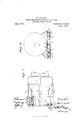
- Figure 1 represents a side elevation of a paper refining engine of the Jordan type and an electric motor for driving the same provided with attaching means to the refining engine shaft embodying the features of my invention. Parts being broken away and parts in section more clearly illustrate structural features.
- Fig. 2. a detail plan view of the motor supporting base.
- Fig. 3. a transverse section of the same as indicated by line 3-3 of Fig. 2, and Fig. 1, a detail cross-section of the motor coupling as indicated by line 4.t of Fig. 1.
- 1 indicates the shell of the refining engine supported upon a bed 2, and 3 the shaft of said engine, which shaft is suitably mounted in bearings 4 of the usual type.
- the shaft is provided with a plug 5 having the usual cutting knives which co-act with similar cutting knives carried by said plug.
- the shaft and plug are longitudinally adjusted to insure proper relation between the stationary shell knives and those carried by said plug. This adjustment is obtained through an adjusting mechanism under the control of a hand-wheel 6, which handwheel is mounted upon a threaded adjusting spindle 7.
- the bed of the refining engine is provided with an extension base 8 secured thereto, which extension constitutes a motor base, and in some instances the latter may be formed in one piece with the engine base instead of being an attachment as shown.
- the motor base 8, as shown in Fig. 2 is provided with longitudinal troughs 9, which troughs form part of the motor base, there being a pair of separable intermediate troughs 10 secured to the base as shown.
- Each of these troughs are provided with cross-partitions 11, which partitions divide the same into a series of separate cells into each of which is mounted a roller 12 provided with a peripheral V-shaped groove, the rollers being arranged to rotate in an oil bath contained in the cells as is shown in Fig. 1.
- a table 13 which table for convenience in construction, is formed in halves being overlapped and centrally secured together by bolts 14:.
- the lower face of the table is provided with V-shaped longitudinal ribs 15, which ribs constitute rails adapted to fit within the V-shaped grooves of the rollers.
- the longitudinal upper edges of the table are confined by strips 16, the strips being secured to the motor base and overlap said table edges.
- the casing or frame 17 of an electric motor is secured to the table by bolts 18, the motor being provided with the usual shaft 19 revolubly mounted in its casing or frame and arranged to have slight longitudinal play in said bearings, which play is common to motors of this class and is provided for the purpose of insuring efficient results in its operation.
- the proportions of the motor casing or frame are such that when it is secured upon the table its shaft is in axial alinement with the plug shaft 3 of the refining engine.
- a flanged collar 20 Secured to the end of the shaft 3 is a flanged collar 20, to which collar is bolted a flanged collar 21, the two collars constituting a coupling member between the motor shaft 19 and engine shaft 3.
- the flanged collar 21 is sleeved upon the motor shaft 19 and in splined connection therewith, being provided with an external groove 22 for the reception of spanners 23, which spanners are bolted or otherwise secured to the motor casing or frame as shown in Fig. 1.
- WVhile I have shown an electric motor adjusted by my improved mechanism, it is obvious that said mechanism may be always applied to a pulley, in which instance the spanner arms 23 would be secured to the frame or shaft bearings of said pulley, which bearings would be the equivalent of the motor casing or frame 17.
- a single member may be connected to the plug shaft 3, in which case the member would be provided with an annular groove 22, the result of such construction, it is apparent, would be the equivalent of that shown.
- a refining engine the combination of a stationary shell, a supporting bed for the shell, a plug rotatively mounted within the shell, an endwise adjustable shaft on which the plug is supported, a motor casing adjustably mounted upon the refining engine bed, a motor revoluble in the casing, the motor shaft being in axial alincment with the plug shaft, a collar secured to said plug shaft, another collar secured to the first named collar having a sleeve extending over the motor shaft, the sleeve being in splined connection with said motor shaft, an annular groove in the last named collar and spanner arms secured to the motor casin having ends engageable with the annular groove of the aforesaid collar.
- a refining engine the combination of a stationary shell, a supporting bed for the shell, a plug rotatively mounted within said shell, an endwise adjustable shaft on which the plug is supported, a bed extension carried by the refining engine bed, longitudinal troughs in connection with the bed extension, the troughs being provided with a series of lateral partitions whereby separate cells are formed, V-shaped groove rollers revolubly mounted in the trough cells, a table having V-shapcd rails depending therefrom and engageable with the V-shaped rollers, guide strips secured to the bed extension and overlapping said table, a motor casing secured to the table, a motor shaft revoluble in bearings of the casing, a coupling secured to the plug shaft, a sleeve extension in connection with the coupling for engagement with the motor shaft, the motor shaft being in splined connection with said sleeve, an annular groove in the aforesaid sleeve, and spanner arms secured to
- a stationary shell and supporting bed for the shell and plug rotatively mounted within the shell, an endwise adjustable shaft on which the plug is supported, an independent driving mechanism for the engine comprising a frame, a shaft mounted in the frame, the shaft being in axial alinement with the engine plug shaft, a grooved collar secured to said plug shaft, the grooved collar being provided with a sleeve extension in splined engagement with the shaft of the driving mechanism, and spanner arms secured to the driv ing mechanism frame, having ends engageable with the collar groove whereby the driving mechanism frame is adjusted inclependently of its shaft.
Landscapes
- Engineering & Computer Science (AREA)
- Mechanical Engineering (AREA)
- Food Science & Technology (AREA)
- Crushing And Pulverization Processes (AREA)
Description
F. B. SAEGKER.
DRIVING MEUHANISM FOR PAPER REPINING ENGINES.
APPLICATION FILED OCT. 18, 1909.
2 SHEETS-SHEET 1.
Patented; Mar. 15, 1910.
ANDFEW B (imam co FHOTO-LIYNDGFAPnERS WASHIHGTON, n c.
I. E. SAEGKER.
DRIVING MECHANISM FOR PAPER REFINING E NemE s.
APPLICATION FILED OCT. 18, 1909.
Patented. Mar. 15, 1910.
2 SHEETS-SHEET 2.
ANDREW a cRAvAM cu. PMOWLITHOGRAPMERS wAsmNsYoN, 0Y0
FRANK E. SAECKER, 0F APPLETON, WISCONSIN.
DRIVING MECHANISM FOR PAPER-BEFINING ENGINES.
Specification of Letters Patent.
Application filed October 18, 1909. Serial No. 523,177.
To all whom it may concern:
Be it. known that I, FRANK E. SAECKER, a citizen of the United States, and resident of Appleton, in the county of Outagamie and State of Wisconsin, have invented certain new and useful Improvements in Driving Mechanism for Paper-Refining Engines; and I do hereby declare that the following is a full, clear, and exact. description thereof.
The object of my invention is to provide simple, economical and effective means for coupling driving mechanisms to the plug shafts of paper refining engines, its construction and arrangement being such that the driving mechanism is longitudinally ad justed with relation to the plug shaft, lateral strain of the driving mechanism shaft being eliminated owing to the factthat the power applied to move said driving mechanism is eXerted upon the casing or frame of the same independent of its shaft. The driving mechanism in this instance being shown as an electric motor.
The invention therefore consists in certain peculiarities of construction and combination of parts to be fully set forth hereinafter with reference to the accompanying drawings and subsequently claimed.
In the drawings Figure 1 represents a side elevation of a paper refining engine of the Jordan type and an electric motor for driving the same provided with attaching means to the refining engine shaft embodying the features of my invention. Parts being broken away and parts in section more clearly illustrate structural features. Fig. 2. a detail plan view of the motor supporting base. Fig. 3. a transverse section of the same as indicated by line 3-3 of Fig. 2, and Fig. 1, a detail cross-section of the motor coupling as indicated by line 4.t of Fig. 1.
Referring by numerals to the drawings, 1 indicates the shell of the refining engine supported upon a bed 2, and 3 the shaft of said engine, which shaft is suitably mounted in bearings 4 of the usual type. The shaft is provided with a plug 5 having the usual cutting knives which co-act with similar cutting knives carried by said plug. As is the case with refining engines of this type, the shaft and plug are longitudinally adjusted to insure proper relation between the stationary shell knives and those carried by said plug. This adjustment is obtained through an adjusting mechanism under the control of a hand-wheel 6, which handwheel is mounted upon a threaded adjusting spindle 7. The bed of the refining engine is provided with an extension base 8 secured thereto, which extension constitutes a motor base, and in some instances the latter may be formed in one piece with the engine base instead of being an attachment as shown. The motor base 8, as shown in Fig. 2, is provided with longitudinal troughs 9, which troughs form part of the motor base, there being a pair of separable intermediate troughs 10 secured to the base as shown. Each of these troughs are provided with cross-partitions 11, which partitions divide the same into a series of separate cells into each of which is mounted a roller 12 provided with a peripheral V-shaped groove, the rollers being arranged to rotate in an oil bath contained in the cells as is shown in Fig. 1. Supported upon the several series of rollers is a table 13, which table for convenience in construction, is formed in halves being overlapped and centrally secured together by bolts 14:. The lower face of the table is provided with V-shaped longitudinal ribs 15, which ribs constitute rails adapted to fit within the V-shaped grooves of the rollers. The longitudinal upper edges of the table are confined by strips 16, the strips being secured to the motor base and overlap said table edges.
The casing or frame 17 of an electric motor is secured to the table by bolts 18, the motor being provided with the usual shaft 19 revolubly mounted in its casing or frame and arranged to have slight longitudinal play in said bearings, which play is common to motors of this class and is provided for the purpose of insuring efficient results in its operation. The proportions of the motor casing or frame, are such that when it is secured upon the table its shaft is in axial alinement with the plug shaft 3 of the refining engine.
Secured to the end of the shaft 3 is a flanged collar 20, to which collar is bolted a flanged collar 21, the two collars constituting a coupling member between the motor shaft 19 and engine shaft 3. The flanged collar 21 is sleeved upon the motor shaft 19 and in splined connection therewith, being provided with an external groove 22 for the reception of spanners 23, which spanners are bolted or otherwise secured to the motor casing or frame as shown in Fig. 1.
From the foregoing description it will be Patented Mar. 15, 1910.
seen that when the plug 5 is adjusted by means of the adjusting wheel 6, longitudinal movement of the plug shaft 3 will, through coupling connection and spanner arm 23, cause the motor to move with said plug shaft and thus all strain incidental to the adjustment is taken off of the motor shaft, which is free to have its normal play. WVhen the motor casing or frame is thus moved back or forth, the table 14 will have a longitudinal movement upon the rollers 9 and 10 due to engagement of the rails 15 within the grooves of said rollers.
By utilizing a double set of rollers as described it will also be seen that lateral play of the table is avoided, which table is held rigidly to the rollers by means of strips 16, the friction of these parts being thus reduced to a minimum and the V-shaped rollers, while permitting free movement longitudinally, also prevent lateral movement without resorting to other rollers or anti-friction de vices for accomplishing this result.
Heretofore paper refining engines have been driven by and connected to electric motors, but in such instances the motor casing has either been adjusted longitudinally by means independent of the plug adjustment mechanism, or the motor and its shaft has either been fixed or directly adjusted through power applied to the motor shaft the effect of which would cause undue strain on said motor shaft and a consequent displacement of the same relative to the fixed parts of said motor. In my present construction the motor is adjusted with the plug shaft, but said plug shaft exerts direct strain only upon the casing or frame and thus the objectionable features before mentioned are overcome.
WVhile I have shown an electric motor adjusted by my improved mechanism, it is obvious that said mechanism may be always applied to a pulley, in which instance the spanner arms 23 would be secured to the frame or shaft bearings of said pulley, which bearings would be the equivalent of the motor casing or frame 17.
In some instances in place of utilizing a two part coupler as shown in Fig. 1, a single member may be connected to the plug shaft 3, in which case the member would be provided with an annular groove 22, the result of such construction, it is apparent, would be the equivalent of that shown.
I claim:
1. In a refining engine, the combination of a stationary shell, a supporting bed for the shell, a plug rotatively mounted within the shell, an endwise adjustable shaft on which the plug is supported, a motor casing adjustably mounted upon the refining engine bed, a motor revoluble in the casing, the motor shaft being in axial alincment with the plug shaft, a collar secured to said plug shaft, another collar secured to the first named collar having a sleeve extending over the motor shaft, the sleeve being in splined connection with said motor shaft, an annular groove in the last named collar and spanner arms secured to the motor casin having ends engageable with the annular groove of the aforesaid collar.
2. In a refining engine, the combination of a stationary shell, a supporting bed for the shell, a plug rotatively mounted within said shell, an endwise adjustable shaft on which the plug is supported, a bed extension carried by the refining engine bed, longitudinal troughs in connection with the bed extension, the troughs being provided with a series of lateral partitions whereby separate cells are formed, V-shaped groove rollers revolubly mounted in the trough cells, a table having V-shapcd rails depending therefrom and engageable with the V-shaped rollers, guide strips secured to the bed extension and overlapping said table, a motor casing secured to the table, a motor shaft revoluble in bearings of the casing, a coupling secured to the plug shaft, a sleeve extension in connection with the coupling for engagement with the motor shaft, the motor shaft being in splined connection with said sleeve, an annular groove in the aforesaid sleeve, and spanner arms secured to the motor casing having ends engageable with the annular sleeve groove.
3. In a refining engine, a stationary shell and supporting bed for the shell and plug rotatively mounted within the shell, an endwise adjustable shaft on which the plug is supported, an independent driving mechanism for the engine comprising a frame, a shaft mounted in the frame, the shaft being in axial alinement with the engine plug shaft, a grooved collar secured to said plug shaft, the grooved collar being provided with a sleeve extension in splined engagement with the shaft of the driving mechanism, and spanner arms secured to the driv ing mechanism frame, having ends engageable with the collar groove whereby the driving mechanism frame is adjusted inclependently of its shaft.
In testimony that I claim the foregoing I have hereunto set my hand at Appleton in the county of Outagamie and State of VVisconsin in the presence of two witnesses.
FRANK E. SAECKER.
IVitnesses SUSIE B. ROSE, Mrs. H. F. I-IEoKERT.
Priority Applications (1)
| Application Number | Priority Date | Filing Date | Title |
|---|---|---|---|
| US52317709A US951919A (en) | 1909-10-18 | 1909-10-18 | Driving mechanism for paper-refining engines. |
Applications Claiming Priority (1)
| Application Number | Priority Date | Filing Date | Title |
|---|---|---|---|
| US52317709A US951919A (en) | 1909-10-18 | 1909-10-18 | Driving mechanism for paper-refining engines. |
Publications (1)
| Publication Number | Publication Date |
|---|---|
| US951919A true US951919A (en) | 1910-03-15 |
Family
ID=3020329
Family Applications (1)
| Application Number | Title | Priority Date | Filing Date |
|---|---|---|---|
| US52317709A Expired - Lifetime US951919A (en) | 1909-10-18 | 1909-10-18 | Driving mechanism for paper-refining engines. |
Country Status (1)
| Country | Link |
|---|---|
| US (1) | US951919A (en) |
-
1909
- 1909-10-18 US US52317709A patent/US951919A/en not_active Expired - Lifetime
Similar Documents
| Publication | Publication Date | Title |
|---|---|---|
| US1943142A (en) | Roller mill adjusting device | |
| US301020A (en) | Portable grin | |
| US457395A (en) | David r | |
| US560231A (en) | Slitting-machine | |
| US1932166A (en) | Thrust bearings for chippers | |
| US957277A (en) | Motor-driving mechanism. | |
| US398048A (en) | hutchinson | |
| US240282A (en) | Grinding-mill | |
| US965771A (en) | Driving mechanism for paper-refining engines. | |
| US540334A (en) | Mangle | |
| US537526A (en) | Resawing-machine | |
| US466251A (en) | moore | |
| US1031284A (en) | Lathe. | |
| US261697A (en) | Roller-mill | |
| US385284A (en) | Wood planing machine | |
| US966273A (en) | Driving mechanism for paper-refining engines. | |
| US1350748A (en) | Crushing-roll machine | |
| US762586A (en) | Decorticator. | |
| US834713A (en) | Refining-engine. | |
| US124776A (en) | Improvement in clamps | |
| US1287868A (en) | Key-seating machine. | |
| US79513A (en) | Improvement in straw-cutters | |
| US884536A (en) | Pipe-cutter. | |
| US1521795A (en) | Conical crushing mill | |
| US118173A (en) | Improvement in machines for throating spokes |