US951877A - Chime-whistle. - Google Patents
Chime-whistle. Download PDFInfo
- Publication number
- US951877A US951877A US32920906A US1906329209A US951877A US 951877 A US951877 A US 951877A US 32920906 A US32920906 A US 32920906A US 1906329209 A US1906329209 A US 1906329209A US 951877 A US951877 A US 951877A
- Authority
- US
- United States
- Prior art keywords
- valve
- whistle
- steam
- bell
- stem
- Prior art date
- Legal status (The legal status is an assumption and is not a legal conclusion. Google has not performed a legal analysis and makes no representation as to the accuracy of the status listed.)
- Expired - Lifetime
Links
- 238000005192 partition Methods 0.000 description 3
- 102100032091 ALK and LTK ligand 2 Human genes 0.000 description 1
- 101000776351 Homo sapiens ALK and LTK ligand 2 Proteins 0.000 description 1
- 208000007256 Nevus Diseases 0.000 description 1
- 208000036366 Sensation of pressure Diseases 0.000 description 1
- 238000009825 accumulation Methods 0.000 description 1
- BFPSDSIWYFKGBC-UHFFFAOYSA-N chlorotrianisene Chemical compound C1=CC(OC)=CC=C1C(Cl)=C(C=1C=CC(OC)=CC=1)C1=CC=C(OC)C=C1 BFPSDSIWYFKGBC-UHFFFAOYSA-N 0.000 description 1
- 238000010276 construction Methods 0.000 description 1
- 230000000694 effects Effects 0.000 description 1
- 230000000717 retained effect Effects 0.000 description 1
Images
Classifications
-
- G—PHYSICS
- G10—MUSICAL INSTRUMENTS; ACOUSTICS
- G10K—SOUND-PRODUCING DEVICES; METHODS OR DEVICES FOR PROTECTING AGAINST, OR FOR DAMPING, NOISE OR OTHER ACOUSTIC WAVES IN GENERAL; ACOUSTICS NOT OTHERWISE PROVIDED FOR
- G10K9/00—Devices in which sound is produced by vibrating a diaphragm or analogous element, e.g. fog horns, vehicle hooters or buzzers
- G10K9/02—Devices in which sound is produced by vibrating a diaphragm or analogous element, e.g. fog horns, vehicle hooters or buzzers driven by gas; e.g. suction operated
- G10K9/04—Devices in which sound is produced by vibrating a diaphragm or analogous element, e.g. fog horns, vehicle hooters or buzzers driven by gas; e.g. suction operated by compressed gases, e.g. compressed air
Definitions
- ln carrying ⁇ out the invention l provide a whistle which comprises a bowl 1 and a bell 2.
- the bell is provided with the usual stem 3, which is enlarged at the bottom and screwthreaded int-o the annular center-piece 4- of the bowl 1.
- a plate is screwed on the outside of' the center-piece 4, the said plate being suiliciently small to produce an annui lar opening G to permit the escape of steam against the lower' edge of the bell 2.
- the main steam valve 7 closes the entrance of steam to the interior of the bowl 1, such entrance being through the stem 8.
- This stem is internally screwthreaded, as shown, for attachment to the steam pipe.
- a piston 9 ln connection with the steam valve 7 is a piston 9.
- the piston 9 is shown as formed integrally with the valve. t is of larger size than the valve, and makes a close steamtight fit with the cylindrical interior of the centerpiece d, which cylindrical interior constitutes the cylinder within which the piston 9 will work.
- the piston can slide up and down within this cylinder to open and close the valve 7.
- This valve is provided with guiding wings 10 on its lower face, so that it will always be properly alined.
- a steam port 11 passes through the valve 7 and communicates with the upper side of the piston 9.
- the stem 3 of the bell 2 is provided with a central port l2 which communicates with the inside of the chamber Lla formed or" the Specification of letters Patent. Pwntgd' Nimm 15, 1910), Application filed August 4, 1906.
- the valve 2t is an auxiliary valve for controlling the passage of steam to the main valve 7 and opening and closing the same.
- the valve 2O is carried within a plug 21 which is screwed into an enlargement of the port 12 of' the stem 3.
- This plug 2l is provided with a transverse port 22, which is contiguous to an opening 23 to permit the escape of steam into one ot the sections of the chime whistle.
- the stem 3 of the bell extends upward above the cover some distance, and is there screwthreaded for the attachment ot' a cap 24.
- This cap 2li carries a pin or plug 25 which engages with the finger 19 immediately over the stem of the valve 20.
- A. bracket 26 surrounds the stem 3 and is clamped against the cover 1G by the cap 24.
- This bracket 26 carries an operating lever 27, which extends to one side of the whistle in the usual manner for attachment of the operating cord.
- a casing 2S incloses the moving mechanism on top of the whistle, and provides a suitable finish for the entire device.
- the operating circuits for the magnets (not shown) pass through openings in the cover 16.
- the valve will be retained closely upon its seat. l
- the steam will also pass into the port 12 of the stem 3, but escape will be prevented by means ot' the auxiliary valve 20.
- the magnets 17 are iirst excited, which will attract the armature 1S, and through the agency of the finger 19 will depress the stem of the auxiliary valve 20, opening theflattcr and permitting the escape ot the steam from the port 12 into the atmosphere.
- the port 12 is larger than the port 11, the steam will escape trom the, chamber la quicker than it can enter the same; consequently the pressure upon the top of the piston 9 will be reduced, and the valve 7 will be lifted ott" o't its seat by the pressure ot the steam under it.
- this whistle is extremely compact, containing, as it does, the main valve within the bowl and the operating magnets and auxiliary valve within the bell, and that it is self-contained and may be attached to the steam pipe as in the manner ot an ordinary whistle not liaving the electrical appliance.
- a whistle having ⁇ in combination a Pressure will immediately ac ⁇ bowl, a bell and a stem, a main valve in the bowl and an auxiliary valve in the bell, the stem being hollow, the hollow serving a means of communication between the two valves, there being means for actuating the auxiliary valve.
- a chime whistle having in combination, aV bell containing a plurality ot compartments of different lengths, a main valve, and an auxiliary valve within the bell and in cooperative relation with the main valve to control the operation ot said main valve, and electro-magnetic means located in the space beyond a shortcompartment, such electro-magnetic means being operatively connected to the auxiliary valve.
- a whistle the combination with the bowl, ot a main valve within the bowl, bell, an auxiliary valve within the bell, a stem, a means ot communication between the two valves, such means being through the stem, and means within the bell tor actuating the auxiliary valve.
- a whistle having in combination a bell, a main valve, an auxiliary valve within the bell and in cooperative relation with the main valve 'to control the operation or. said main valve, and electro-magnetic means located within the bell and operatively7 connectcd to the auxiliary valve, and additional.
- operative means located outside of the bell and operatively connected to the auxiliary valve.
- a whistle having a chamber, a main valve, a piston operatively connected there4 to, the said piston lying within the chamber.
- means ttor securing an accumulation oli pressure within the chamber, teudii'ig to seat the valve, such means including a port which passes through the piston and means tor rclieving pressure within the chamber. permitting the valve to open.
- t3, t steam whistle having in combination a chamber, a main valve, a piston operatively connected thereto and working within the chamber.
- the piston being connected to the stem ot the valve with a st am passage through such stem, admitting steam trom one tace o'l the valve to one side ot' the piston, and means for controlling the travel ot steam through such passage.
Landscapes
- Physics & Mathematics (AREA)
- Engineering & Computer Science (AREA)
- Acoustics & Sound (AREA)
- Multimedia (AREA)
- Toys (AREA)
Description
AYLWARD. GHIME WHISTLE.
APPLICATION FILED AUGA, 1906.
Patented Man-15,1910,
5 w am M vAmmer.' sv annum co. Fumo-mnuGMPHERs, wAsmNGYoN D c l NETE@ TATlS PATEN HENRY W. AYLVJARO, OF NEW' YORK, N. Y.
, ASSIGNOR TO 'El-1E SGANAL AND CONTROL COMPANY, A CORPORATION OF NEVI YORK.
CHIME-HISTLE.
asista.
To all 'wv/'rom it may concern:
Be it known that l, HENRY lV. AYLwAnn, a citizen of the United States, residing in the borough of Brooklyn, city of N ew York, State of New York, have invented a certain new and useful Chi1ne-`Whistle, of which the following is a description.
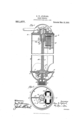
The object l have in view is the production of a chime whistle which will be electrically operated and which at the same time will have the appearance of an ordinary manuallycperated chime whistle, and which will be compact, composed of few parts, and entirely self-contained. I attain these objects by the mechanism illustrated in the accompanying drawings, which show one embodiment of the invention and in whichv Figure 1 is a vertical longitudinal section of the whistle taken on the line 1--1 of Fig. 2, and Fig. 2 is a horizontal section of the same taken on the line 2-2 of Fig. l.
ln both views like parts are designated by the same reference characters.
ln carrying` out the invention l provide a whistle which comprises a bowl 1 and a bell 2. The bell is provided with the usual stem 3, which is enlarged at the bottom and screwthreaded int-o the annular center-piece 4- of the bowl 1. A plate is screwed on the outside of' the center-piece 4, the said plate being suiliciently small to produce an annui lar opening G to permit the escape of steam against the lower' edge of the bell 2. The main steam valve 7 closes the entrance of steam to the interior of the bowl 1, such entrance being through the stem 8. This stem .is internally screwthreaded, as shown, for attachment to the steam pipe.
ln connection with the steam valve 7 is a piston 9. The piston 9 is shown as formed integrally with the valve. t is of larger size than the valve, and makes a close steamtight fit with the cylindrical interior of the centerpiece d, which cylindrical interior constitutes the cylinder within which the piston 9 will work. The piston can slide up and down within this cylinder to open and close the valve 7. rThis valve is provided with guiding wings 10 on its lower face, so that it will always be properly alined. A steam port 11 passes through the valve 7 and communicates with the upper side of the piston 9. The stem 3 of the bell 2 is provided with a central port l2 which communicates with the inside of the chamber Lla formed or" the Specification of letters Patent. Pwntgd' Nimm 15, 1910), Application filed August 4, 1906.
Serial No. 329,209.
such that the desired musical note will be produced in order to constitute the chime effect of the whistle. lWithin the space formed between the partition l5 and the top .16 of the bell are located the operating magnets 17. The compartment produced by the partition 15, the partitions 13 and the outside of the bell is of adequate size to contain magnets of the necessary power. These magnets actuate an armature 18 which has a linger 19 which extends toward the center' of the bell. This finger engages with the stem of a valve 20. The valve 2t) is an auxiliary valve for controlling the passage of steam to the main valve 7 and opening and closing the same. The valve 2O is carried within a plug 21 which is screwed into an enlargement of the port 12 of' the stem 3. This plug 2l is provided with a transverse port 22, which is contiguous to an opening 23 to permit the escape of steam into one ot the sections of the chime whistle.
The stem 3 of the bell extends upward above the cover some distance, and is there screwthreaded for the attachment ot' a cap 24. This cap 2li carries a pin or plug 25 which engages with the finger 19 immediately over the stem of the valve 20. A. bracket 26 surrounds the stem 3 and is clamped against the cover 1G by the cap 24. This bracket 26 carries an operating lever 27, which extends to one side of the whistle in the usual manner for attachment of the operating cord.
A casing 2S incloses the moving mechanism on top of the whistle, and provides a suitable finish for the entire device. The operating circuits for the magnets (not shown) pass through openings in the cover 16.
The operation is as follows: Steam will enter the stem S andtend to lift the valve 7 from its seat. It will pass through the port 11 and enter the chamber la and will exert a pressure downward on the piston 9. As the latter is larger in area than the valve 7,
the valve will be retained closely upon its seat. lThe steam will also pass into the port 12 of the stem 3, but escape will be prevented by means ot' the auxiliary valve 20. To operate the whistle, the magnets 17 are iirst excited, which will attract the armature 1S, and through the agency of the finger 19 will depress the stem of the auxiliary valve 20, opening theflattcr and permitting the escape ot the steam from the port 12 into the atmosphere. As the port 12 is larger than the port 11, the steam will escape trom the, chamber la quicker than it can enter the same; consequently the pressure upon the top of the piston 9 will be reduced, and the valve 7 will be lifted ott" o't its seat by the pressure ot the steam under it. The steam will then pass from the bowl 1 through the annular opening t3 and actuate the whistle. Upon the magnets being` deenergized, the auxiliary valve E20 will be closed by the pressure oi the steam against its lower face, thereby preventing escape ot' steam from the chamber et, cumulate within this chamber through the port 11, overbalancing the upward pres sure oi the steam on the valve 7 and closing` the latter. In operating the valve man ually, by depressingI the lever 27 the auxiliary valve 20 can be opened, and the main steam Valve will operate in the same manner as before.
lt will be seen from the preceding description that this whistle is extremely compact, containing, as it does, the main valve within the bowl and the operating magnets and auxiliary valve within the bell, and that it is self-contained and may be attached to the steam pipe as in the manner ot an ordinary whistle not liaving the electrical appliance.
t Another advantage of my improved whistle is that the main valve is vertical. as shown, which permits it to be of adequate size, and at the. same time to lie entirely within the bowl. By this construction there are no steam joints outside oit the bowl, and all ports are within the bowl, hence there are no ditticultics in securing the absence ot leakage. Another advantage lies in the tact that no seating` spring is required. the valve tending to seat by its own weight. hence it responds very quickly to actions oi the auxiliary valve.
Having now described my invention, what I claim is new and desire to secure by Letters Patent is:
1. A whistle having` in combination a Pressure will immediately ac` bowl, a bell and a stem, a main valve in the bowl and an auxiliary valve in the bell, the stem being hollow, the hollow serving a means of communication between the two valves, there being means for actuating the auxiliary valve.
2. A chime whistle having in combination, aV bell containing a plurality ot compartments of different lengths, a main valve, and an auxiliary valve within the bell and in cooperative relation with the main valve to control the operation ot said main valve, and electro-magnetic means located in the space beyond a shortcompartment, such electro-magnetic means being operatively connected to the auxiliary valve.
3. In a whistle, the combination with the bowl, ot a main valve within the bowl, bell, an auxiliary valve within the bell, a stem, a means ot communication between the two valves, such means being through the stem, and means within the bell tor actuating the auxiliary valve.
4l. A whistle having in combination a bell, a main valve, an auxiliary valve within the bell and in cooperative relation with the main valve 'to control the operation or. said main valve, and electro-magnetic means located within the bell and operatively7 connectcd to the auxiliary valve, and additional.
operative means located outside of the bell and operatively connected to the auxiliary valve.
A whistle having a chamber, a main valve, a piston operatively connected there4 to, the said piston lying within the chamber. means ttor securing an accumulation oli pressure within the chamber, teudii'ig to seat the valve, such means including a port which passes through the piston and means tor rclieving pressure within the chamber. permitting the valve to open.
t3, t steam whistle, having in combination a chamber, a main valve, a piston operatively connected thereto and working within the chamber. the piston being connected to the stem ot the valve with a st am passage through such stem, admitting steam trom one tace o'l the valve to one side ot' the piston, and means for controlling the travel ot steam through such passage.
This specification signed and witnessed this 27th day of July, 1906.
HENRY lV. YLWTARD. 'Vitnesses LEONARD H. Drnn, AUG. LONG.
Priority Applications (1)
| Application Number | Priority Date | Filing Date | Title |
|---|---|---|---|
| US32920906A US951877A (en) | 1906-08-04 | 1906-08-04 | Chime-whistle. |
Applications Claiming Priority (1)
| Application Number | Priority Date | Filing Date | Title |
|---|---|---|---|
| US32920906A US951877A (en) | 1906-08-04 | 1906-08-04 | Chime-whistle. |
Publications (1)
| Publication Number | Publication Date |
|---|---|
| US951877A true US951877A (en) | 1910-03-15 |
Family
ID=3020287
Family Applications (1)
| Application Number | Title | Priority Date | Filing Date |
|---|---|---|---|
| US32920906A Expired - Lifetime US951877A (en) | 1906-08-04 | 1906-08-04 | Chime-whistle. |
Country Status (1)
| Country | Link |
|---|---|
| US (1) | US951877A (en) |
Cited By (1)
| Publication number | Priority date | Publication date | Assignee | Title |
|---|---|---|---|---|
| US3008683A (en) * | 1959-07-10 | 1961-11-14 | Sloan Valve Co | Flush valves |
-
1906
- 1906-08-04 US US32920906A patent/US951877A/en not_active Expired - Lifetime
Cited By (1)
| Publication number | Priority date | Publication date | Assignee | Title |
|---|---|---|---|---|
| US3008683A (en) * | 1959-07-10 | 1961-11-14 | Sloan Valve Co | Flush valves |
Similar Documents
| Publication | Publication Date | Title |
|---|---|---|
| US624890A (en) | Valve-controlling device | |
| US1828517A (en) | Flush valve | |
| US895426A (en) | Pressure-reducing valve. | |
| US1984167A (en) | Balanced valve for pipe organs | |
| US687247A (en) | Valve. | |
| US1009268A (en) | Piano-playing mechanism and the like. | |
| US1665832A (en) | Flush valve | |
| US1138849A (en) | Individual pneumatic-action mechanism. | |
| US1604467A (en) | Electropneumatic organ valve | |
| US1551618A (en) | Organ | |
| US2746338A (en) | Pipe organ improved pitman windchests | |
| US1883838A (en) | Pneumatically balanced valve | |
| US633415A (en) | Valve-actuating device. | |
| US1195536A (en) | Fobnia | |
| US1292362A (en) | Pneumatic action for musical instruments. | |
| US537664A (en) | Pipe-organ | |
| US824079A (en) | Electric organ-action. | |
| US1182133A (en) | Time controlling and recording mechanism. | |
| US1180871A (en) | Pneumatic action for pianos. | |
| US1823775A (en) | Electropneumatic action for the operation and control of musical instruments | |
| US1626192A (en) | Pneumatic-control device | |
| US536975A (en) | Electrically-controlled magnet and valve for pipe-organs | |
| US231786A (en) | Pneumatic action for musical instruments | |
| US1632657A (en) | Cipherless device for pipe organs | |
| US1164632A (en) | Pneumatic action. |