US9518752B2 - Recording medium storing apparatus control program, apparatus control system, and apparatus control device - Google Patents
Recording medium storing apparatus control program, apparatus control system, and apparatus control device Download PDFInfo
- Publication number
- US9518752B2 US9518752B2 US14/165,959 US201414165959A US9518752B2 US 9518752 B2 US9518752 B2 US 9518752B2 US 201414165959 A US201414165959 A US 201414165959A US 9518752 B2 US9518752 B2 US 9518752B2
- Authority
- US
- United States
- Prior art keywords
- vibration
- data
- vibration data
- medium
- apparatus control
- Prior art date
- Legal status (The legal status is an assumption and is not a legal conclusion. Google has not performed a legal analysis and makes no representation as to the accuracy of the status listed.)
- Expired - Fee Related, expires
Links
Images


Classifications
-
- F24F11/006—
-
- F—MECHANICAL ENGINEERING; LIGHTING; HEATING; WEAPONS; BLASTING
- F24—HEATING; RANGES; VENTILATING
- F24F—AIR-CONDITIONING; AIR-HUMIDIFICATION; VENTILATION; USE OF AIR CURRENTS FOR SCREENING
- F24F11/00—Control or safety arrangements
- F24F11/30—Control or safety arrangements for purposes related to the operation of the system, e.g. for safety or monitoring
-
- F—MECHANICAL ENGINEERING; LIGHTING; HEATING; WEAPONS; BLASTING
- F24—HEATING; RANGES; VENTILATING
- F24F—AIR-CONDITIONING; AIR-HUMIDIFICATION; VENTILATION; USE OF AIR CURRENTS FOR SCREENING
- F24F11/00—Control or safety arrangements
- F24F11/50—Control or safety arrangements characterised by user interfaces or communication
- F24F11/52—Indication arrangements, e.g. displays
- F24F11/523—Indication arrangements, e.g. displays for displaying temperature data
-
- F—MECHANICAL ENGINEERING; LIGHTING; HEATING; WEAPONS; BLASTING
- F24—HEATING; RANGES; VENTILATING
- F24F—AIR-CONDITIONING; AIR-HUMIDIFICATION; VENTILATION; USE OF AIR CURRENTS FOR SCREENING
- F24F11/00—Control or safety arrangements
- F24F11/62—Control or safety arrangements characterised by the type of control or by internal processing, e.g. using fuzzy logic, adaptive control or estimation of values
- F24F11/63—Electronic processing
- F24F11/64—Electronic processing using pre-stored data
-
- G—PHYSICS
- G05—CONTROLLING; REGULATING
- G05D—SYSTEMS FOR CONTROLLING OR REGULATING NON-ELECTRIC VARIABLES
- G05D23/00—Control of temperature
- G05D23/19—Control of temperature characterised by the use of electric means
- G05D23/1902—Control of temperature characterised by the use of electric means characterised by the use of a variable reference value
- G05D23/1905—Control of temperature characterised by the use of electric means characterised by the use of a variable reference value associated with tele control
-
- F—MECHANICAL ENGINEERING; LIGHTING; HEATING; WEAPONS; BLASTING
- F24—HEATING; RANGES; VENTILATING
- F24F—AIR-CONDITIONING; AIR-HUMIDIFICATION; VENTILATION; USE OF AIR CURRENTS FOR SCREENING
- F24F11/00—Control or safety arrangements
- F24F11/62—Control or safety arrangements characterised by the type of control or by internal processing, e.g. using fuzzy logic, adaptive control or estimation of values
- F24F11/63—Electronic processing
- F24F11/65—Electronic processing for selecting an operating mode
- F24F11/66—Sleep mode
-
- F24F2011/0036—
-
- F24F2011/0064—
-
- F24F2011/0065—
-
- F—MECHANICAL ENGINEERING; LIGHTING; HEATING; WEAPONS; BLASTING
- F24—HEATING; RANGES; VENTILATING
- F24F—AIR-CONDITIONING; AIR-HUMIDIFICATION; VENTILATION; USE OF AIR CURRENTS FOR SCREENING
- F24F2120/00—Control inputs relating to users or occupants
-
- F—MECHANICAL ENGINEERING; LIGHTING; HEATING; WEAPONS; BLASTING
- F24—HEATING; RANGES; VENTILATING
- F24F—AIR-CONDITIONING; AIR-HUMIDIFICATION; VENTILATION; USE OF AIR CURRENTS FOR SCREENING
- F24F2120/00—Control inputs relating to users or occupants
- F24F2120/10—Occupancy
- F24F2120/14—Activity of occupants
Definitions
- the present invention relates to a recording medium storing an apparatus control program, an apparatus control system and an apparatus control device.
- an air conditioner is given.
- an air conditioner is always operated at an air conditioning temperature that its user feels comfortable.
- the air conditioning temperature is set by the user using a remote controller, and operation control of the air conditioner is performed so that the set temperature is kept in the room. If the user feels hot or cold, the comfortableness is kept by the user changing the setting of the air conditioning temperature using the remote controller again.
- the user does not have the remote controller at hand, the user cannot control the operation of the air conditioner. For example, while sleeping, it may happen that the user cannot have the remote controller nearby or cannot find the remote controller because it is too dark or the user is too sleepy.
- a technique is disclosed in which, when it is not possible to operate a remote controller as described above, an air conditioner is controlled on the basis of a user's motion or voice, with the use of an image recognition technique or a voice recognition technique.
- an air conditioner is controlled on the basis of a user's motion or voice, with the use of an image recognition technique or a voice recognition technique.
- the user since the user is generally in a dark environment when sleeping, it may happen that the user cannot perform appropriate image processing or that he/she cannot perform voice recognition in consideration of those around the user.
- Patent Document 1 discloses a technique in which an external impact is a user input signal, as a technique for transmitting a user instruction to an electronic apparatus without making a loud sound under a dark environment.
- Patent Document 1 Japanese Laid-open Patent Publication No. 2006-323943
- the technique in which an external impact is a user input signal is effective to transmit a user instruction to the air conditioner at the time of sleeping in darkness and quietness.
- a non-transitory computer-readable recording medium having stored therein an apparatus control program for controlling an apparatus to be a control target, the apparatus control program causing a computer to execute a process, the process comprising: selecting a vibration medium corresponding to first vibration data, by referring to a reference data storage unit storing reference vibration data in association with vibration medium information identifying the vibration medium, on the basis of matching between the first vibration data and the reference vibration data, the first vibration data corresponding to first vibration transmitted via the vibration medium and detected by a vibration detection unit; selecting reference vibration data corresponding to second vibration data, from among the reference vibration data stored in the reference data storage unit on the basis of the second vibration data and a correction value of the reference vibration data, the second vibration data corresponding to second vibration transmitted via the selected vibration medium and detected by the vibration detection unit; updating a correction value of the selected reference vibration data on the basis of the second vibration data; and generating a control signal for controlling the apparatus on the basis of the selected reference vibration data.
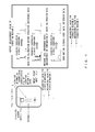
- FIG. 1 is a diagram for illustrating the outline of the present invention
- FIG. 2 is a hardware configuration diagram of an apparatus control device 1 ;
- FIG. 3 is a flowchart showing the process flow of an apparatus control program executed by the apparatus control device 1 ;
- FIG. 4 is a diagram for illustrating the outline of a reference data registration process
- FIGS. 5A and 5B are flowcharts showing the flow of the reference data registration process
- FIG. 5C is a diagram for illustrating the reference data registration process in step S 501 , S 502 and S 503 of FIG. 5A ;
- FIGS. 6A, 6B, 6C and 6D are diagrams showing a structure example of reference data
- FIG. 7 is a diagram for illustrating the outline of a calibration-before-operation process
- FIGS. 8A, 8B, 8C and 8D are diagrams for illustrating a method for matching with the reference data (maximum/standard/minimum);
- FIGS. 9A and 9B are flowcharts showing the flow of the calibration-before-operation process
- FIG. 10 is a diagram for illustrating the outline of a calibration-at-the-time-of-operation process
- FIGS. 11A and 11B are diagrams for illustrating a method for detecting message data
- FIGS. 12A and 12B are flowcharts showing the flow of the calibration-at-the-time-of-operation process and an application example (1) after detection of intention information;
- FIGS. 13A and 13B are flowcharts showing the flow of an application example (2) after detection of the intention information
- FIG. 14 is a diagram showing the hardware configuration of the apparatus control device 1 to which the present invention is applied.
- FIG. 15 is a diagram showing a method for providing a program and data to an information processing apparatus.
- FIG. 1 is a diagram for illustrating the outline of the present invention.
- an apparatus control system 10 to which the present invention is applied is provided with an apparatus control device 1 , a vibration medium 3 and an air conditioner unit 4 .
- an instruction from a user 2 is transmitted to the apparatus control device 1 via the vibration medium 3 , and the apparatus control device 1 which analyzes the instruction controls the operation of the air conditioner unit 4 by executing an apparatus control program to be described later.
- the vibration medium 3 is, for example, a bed.
- the vibration medium 3 transmits vibration information generated by the user 2 to the apparatus control device 1 as an instruction from the user 2 .
- Instructions from the user 2 are roughly classified into two kinds. One is an instruction given by the user 2 consciously hitting the vibration medium 3 with his hand or the like.
- the vibration medium 3 transmits the instruction to the apparatus control device 1 on the basis of the timing of the hit or the number of hits. Such an instruction is referred to as “message data” here.
- the other is an instruction which is generated by a body motion of the user 2 , such as turning over, and unconsciously transmitted, and it is referred to as “body motion data” here.
- the apparatus control device 1 analyzes these instructions generated by the user 2 by executing the apparatus control program, and inputs particular instruction information to the air conditioner unit 4 , for example, via infrared communication or the like.
- the air conditioner unit 4 performs air conditioning in the room in accordance with the inputted particular instruction information. For example, the air conditioner unit 4 performs air conditioning such as turning on or off the power and changing a set temperature.
- FIG. 2 is a hardware configuration diagram of the apparatus control device 1 .
- the apparatus control device 1 is provided with a vibration sensor module 11 , a ROM (Read Only Memory) 12 , a RAM (Random Access Memory) 13 , an external recording device 14 , a temperature sensor module 15 , a humidity sensor module 16 , a CPU (Central Processing Unit) 17 , an RTC (Real Time Clock) 18 , a display module 19 and a control information transmission/reception module 20 .
- the vibration sensor module 11 is, for example, an acceleration sensor which detects vibration transmitted to the apparatus control device 1 via the vibration medium 3 .
- the vibration sensor module 11 , the temperature sensor module 15 and the humidity sensor module 16 may be provided not inside but outside the apparatus control device 1 and externally connected.
- the ROM 12 stores the apparatus control program, reference data and the like.
- the RAM 13 is a memory for executing the apparatus control program and the like. For example, the apparatus control program stored in advance in the ROM 12 is executed, with the RAM 13 as a work memory.
- the external recording device 14 stores calibration data before operation (selected reference data), the amount of correction at the time of operation, detected body motion data and message data, and the like.
- the temperature sensor module 15 detects a room temperature
- the humidity sensor module 16 detects a room humidity.
- the CPU 17 controls the whole apparatus control device 1 by controlling the vibration sensor module 11 , the ROM 12 , the RAM 13 , the external recording device 14 , the temperature sensor module 15 , the humidity sensor module 16 , the RTC 18 , the display module 19 and the control information transmission/reception module 20 .
- the RTC 18 measures current time at the time of acquiring sensor data from the vibration sensor module 11 , the temperature sensor module 15 and the humidity sensor module 16 , at the time of detecting body motion data and message data, and the like.
- the display module 19 displays various information such as existence/non-existence of vibration detection by the vibration sensor module 11 , strength of vibration, temperature and humidity, and the like.
- the control information transmission/reception module 20 controls, for a control information transmission/reception module 40 A of a controlled apparatus 4 A and a control information transmission/reception module 40 B of a controlled apparatus 4 B, communication of power on/off control information, temperature control information and the like about the controlled apparatuses 4 A and 4 B, using infrared rays or the like.
- FIG. 3 is a flowchart showing the flow of the apparatus control program executed by the apparatus control device 1 .
- step S 301 a subroutine, a “reference data registration” process, is executed. Measurement and registration of calibration data and intention information are performed with the use of some vibration media 3 having different characteristics. This becomes reference data. The details of the reference data registration process will be described later.
- step S 302 a subroutine, a “calibration-before-operation” process, is executed. Measurement of calibration data is performed with the use of a vibration medium 3 to be actually used by the user 2 , and a vibration medium 3 most similar to the reference data is searched for and determined. In a “calibration-at-the-time-of-operation” process to be described later, detection is performed on the basis of intention information (message data and body motion data) about the vibration medium 3 determined here. The details of a calibration-before-operation process will be described later.
- step S 303 threshold interruption and periodical timer interruption by the vibration sensor module 11 are set as sleep control of the CPU 17 for power saving.
- step S 304 a subroutine, a “calibration-at-the-time-of-operation” process, is executed.
- the calibration-at-the-time-of-operation process is always executed when the apparatus control system 10 is operated.
- a characteristic difference between the vibration medium 3 for which the reference data is registered and the vibration medium 3 used by the user 2 and a characteristic error due to environment are corrected, so that the accuracy of detecting intention information can be sequentially improved.
- the position of the apparatus control device 1 more specifically, the position of the vibration sensor module 11 at the time of detecting intention information and the place of impact point (vibration point) transmitting the intention information change.
- an object a person, a comforter or the like
- a transmission characteristic error which changes in such cases is referred to as a characteristic error by the environment. The details will be described later.
- FIG. 4 is a diagram for illustrating the outline of the reference data registration process.
- vibration media 3 (a vibration medium A, a vibration medium B and a vibration medium C) having different transmission characteristics, such as a spring coil, low-resilience urethane and sponge, are prepared, and calibration information before operation and intention information are measured in a particular arrangement and stored for each vibration medium 3 .
- Calibration is performed by giving an impact to the vibration media 3 by the hand of the user 2 or a particular jig.
- Conscious information may be created by combining the measured calibration information.
- measurement is performed for each vibration medium 3 by keeping the amount of vibration constant and changing a distance L between the vibration sensor module 11 and an impact point (input) or by keeping the distance L constant and changing the magnitude of the inputted impact. Then, signal increase/decrease information (scale range: “maximum/standard/minimum”) is stored (registered).
- An impact by a hand or the like can be thought to be an impulse input (full-frequency input) to the vibration medium 3 .
- the transmission characteristic of a particular vibration medium 3 can be known on the basis of difference in the attenuating frequency.
- multiple pieces of reference data may be registered for the same vibration medium 3 .
- information having a high correlation with temperature and humidity such as body motion data
- information about temperature and humidity may be registered. In this case, this data may be also used as a threshold at the time of detection.
- FIGS. 5A and 5B are flowcharts showing the flow of the reference data registration process
- FIG. 5C is a diagram for illustrating the reference data registration process in step S 501 , S 502 and S 503 of FIG. 5A
- FIGS. 6A, 6B, 6C and 6D are diagrams showing a structure example of the reference data.
- the reference data registration process is executed for each unit of some vibration media 3 having different transmission characteristics.
- step S 501 measurement is performed by keeping the magnitude of impact constant and changing the distance between the vibration sensor module 11 and an impact point, or by keeping the distance between the vibration sensor module 11 and the impact point constant and changing the magnitude of an inputted impact, and signal increase/decrease information (scale range: “maximum/standard/minimum”) is stored (registered). Then, frequency conversion (Fourier Transform) is performed within each scale range.
- step S 502 method of averaged response or combination of the registered data (body motion data/message data) is performed.
- the message data can also be composed by using data for calibration.
- a time difference (margin) between signals is measured in advance by Cross-Correlation.
- frequency conversion Frourier Transform
- a threshold of Cross-Correlation between the registered data and acquired data, and, as for the message data, a margin range between signals (maximum and minimum), a scale range (maximum and minimum) and thresholds for each block and for each spectrum (maximum and minimum) are set in order to perform detection.
- the intention information having a high correlation with temperature and humidity among the registered data, temperature and humidity thresholds may be registered.
- the registered thresholds may be used as thresholds at the time of detection. An example of each threshold is shown in FIGS. 6A, 6B, 6C and 6D .
- step S 504 the registered data registered in step S 501 is captured as input data at the time of actual operation and it is judged whether or not the input data is detected among the registered body motion data/message data.
- step S 505 it is determined in step S 505 whether remeasurement and recombination are to be performed or the thresholds are to be adjusted. If remeasurement and recombination are to be performed, the flow returns to step S 502 . If the thresholds are to be adjusted, the flow returns to step S 503 .
- step S 504 if the input data is not detected among the registered body motion data/message data (step S 504 : NO), temporary registration of the body motion data and the message data is performed in step S 506 .
- step S 507 detection accuracy is checked. If the accuracy does not satisfy a predetermined condition (step S 507 : NG), the flow proceeds to step S 505 . If the accuracy satisfies the predetermined condition (step S 507 : OK), actual registration of the body motion data and the message data is performed in step S 508 .
- step S 509 it is judged whether registration of the body motion data and the message data has been completed. If the registration has not been completed (step S 509 : NO), the flow returns to step S 502 . If the registration has been completed, the reference data registration process for the next the vibration medium 3 is executed. Then, when the reference data registration process for all the vibration media 3 is completed, a data set as shown in FIGS. 6A, 6B, 6C and 6D is completed.
- FIG. 7 is a diagram for illustrating the outline of the calibration-before-operation process.
- the calibration-before-operation process is a matching process to determine which of the above vibration media 3 for which the reference data is registered the vibration medium 3 used by the user 2 is the most similar to.
- synchronously added data is normalized according to the total amount of energy of the registered reference data for each vibration medium 3 , and then Cross-Correlation with the reference data is performed. Cross-Correlation between measurement data and the registered reference data may be performed. Then, a correlation value is stored for each vibration medium 3 .
- vibration information may be sequentially presented to the user 2 in order to uniform the amount of vibration and increase the measurement accuracy.
- the vibration information may be sequentially presented as a vibration test after the determination of the vibration medium 3 in order for the user 2 to recognize an appropriate amount of vibration (the strength of hitting) before actual operation.
- FIGS. 8A, 8B, 8C and 8D are diagrams for illustrating the method for matching with the reference data (maximum/standard/minimum).
- the total amounts of energy of maximum reference data 81 , standard reference data 82 and minimum reference data 83 are calculated in advance.
- positioning (similarity check) with the standard reference data 82 is performed by performing Cross-Correlation with acquired data 84 as necessary. Then, after the positioning, the total amount of energy of the acquired data is calculated, and it is determined which of the reference data (the maximum reference data 81 , the standard reference data 82 and the minimum reference data 83 ) the acquired data is the most similar to. In the example shown in FIG. 8B , it is judged that the acquired data is the most similar to the standard reference data 82 .
- any of the reference data and the acquired data is normalized.
- the acquired data 84 is normalized, and normalized, acquired data 85 is obtained.
- the reference data is used to perform detection of the acquired data.
- the threshold for each block may be adjusted according to the amount of normalization.
- FIGS. 9A and 9B are flowcharts showing the flow of the calibration-before-operation process.
- step S 901 it is judged whether to perform calibration measurement or to make a selection of a vibration medium 3 .
- step S 905 If a selection of a vibration medium 3 is to be made, the flow proceeds to step S 905 .
- measurement method of averaged response
- step S 902 measurement (method of averaged response) of data for calibration is performed in step S 902 . Specifically, first, the distance between the vibration sensor module 11 and an impact point is presented to the user 2 to adjust the measurement environment to the measurement environment at the time of registration of the reference data. Then, mutual correlation is performed for such data that the amount of vibration is within a threshold range as a target, and method of averaged response is performed for such signals that the correlation value exceeds the threshold. During the measurement, measurement data and the threshold may be sequentially presented to the user 2 .
- step S 903 the synchronously added data is normalized as shown in FIGS. 8A, 8B, 8C and 8D according to the total amount of energy of the registered reference data for each vibration medium 3 , and mutual correlation with the reference data is performed. Then, the correlation value is stored.
- step S 904 frequency conversion (Fourier Transform) of the asynchronously added and normalized measurement data is performed, and a total of values of difference from the vibration media 3 (the reference data) is calculated for each spectrum. Then, the difference values are stored.
- frequency conversion Frier Transform
- steps S 903 and S 904 are repeatedly executed for each of the vibration media 3 for which the reference data is registered.
- step S 905 a vibration medium 3 having a high correlation value and a low difference value is selected on the basis of the correlation values and the difference values, and the reference data (message data and body motion data) of the vibration medium 3 is taken out.
- This reference data is used for calibration at the time of operation, which is to be described later.
- step S 906 it is judged whether or not to perform a vibration test.
- step S 906 If the vibration test is not to be performed (step S 906 : NO), the calibration-before-operation process is ended. If the vibration test is to be performed (step S 906 : YES), the vibration test is performed in step S 907 . Specifically, after positioning is performed on the basis of mutual correlation between the selected vibration medium 3 and the acquired data, matching with the reference data (maximum/standard/minimum) is performed by the method described with the use of FIGS. 8A, 8B, 8C and 8D , and the result is sequentially presented to the user 2 as strength information or the like.
- FIG. 10 is a diagram for illustrating the outline of the calibration-at-the-time-of-operation process.
- the calibration-at-the-time-of-operation process is a process for detecting intention information on the basis of the registered reference data (the vibration medium 3 ) which has been matched in the calibration-before-operation process described above, and vibration information data acquired from the vibration sensor module 11 .
- the vibration medium 3 is different from the registered data due to deterioration over the years, temperature change or the like or a case where an object is steadily placed, and, thus, arrangement of the vibration sensor module 11 and the impact point is different from the arrangement at the time of the calibration-before-operation process. Therefore, the impact point at which an impact is given and the amount of vibration thereof change and the transmission characteristic changes, and the detection accuracy decreases.
- frequency conversion Fast Fourier Transform
- difference from frequency information about the registered reference data is extracted as a correction value for the reference data, as shown in STEP 2 in FIG. 10 .
- This correction value can be uniformed by calculating an average among the past several correction values.
- the correction value for the reference data is obtained from a value of the vibration information data acquired from the vibration sensor module 11 in the frequency domain and performing the detection of intention information described above on the basis of the vibration information data from which the correction value has been subtracted, the detection accuracy in the frequency domain can be improved. Then, by returning the domain to the time domain, the detection accuracy in the time domain can be improved.
- FIGS. 11A and 11B are diagrams for illustrating the method for detecting message data.
- a threshold of mutual correlation between the reference data and the acquired data a margin range (maximum and minimum) between signals, a scale range (maximum and minimum), thresholds for each block and for each spectrum (maximum and minimum), and, if strength of each signal is used as message information, a scale ratio between signals and a tolerance therefor, temperature and humidity thresholds and the like are set.
- a data set as shown in FIGS. 6A, 6B, 6C and 6D is used for the initial values of the setting values.
- the thresholds described above if the width is widened, the number of detection mistakes decreases, and the number of erroneous detections increases. If the width is narrowed, the number of detection mistakes increases, and the number of erroneous detections decreases. It is also possible to sequentially control each threshold using difference information between the reference data and the acquired data (a correction value).
- Reference numeral 111 in FIG. 11A denotes a range between a maximum value and a minimum value for each block of the reference data.
- Reference numeral 114 denotes a maximum value of time difference between a first signal and a second signal; reference numeral 112 denotes a standard value of the time difference between the first signal and the second signal; and reference numeral 116 denotes a minimum value of the time difference between the first signal and the second signal.
- Reference numeral 115 denotes a maximum value of time difference between the second signal and a third signal; reference numeral 113 denotes a standard value of the time difference between the second signal and the third signal; and reference numeral 117 denotes a minimum value of the time difference between the second signal and the third signal.
- Reference numeral 118 in FIG. 11B denotes a range between a maximum value and a minimum value for each spectrum of the reference data.
- FIGS. 12A and 12B are flowcharts showing the flow of the calibration-at-the-time-of-operation process and an application example (1) after detection of intention information
- FIGS. 13A and 13B are flowcharts showing the flow of an application example (2) after detection of intention information.
- the calibration-at-the-time-of-operation process and the application example (1) after detection of intention information shown in FIGS. 12A and 12B is activated by vibration larger than an interruption threshold of the vibration sensor module 11 .
- the application example (2) after detection of intention information shown in FIGS. 13A and 13B is activated by periodical interruption, for example, at intervals of five minutes.
- step S 1201 in FIG. 12A a timer is activated. While this timer is being driven, step S 1202 and subsequent steps to be described later are executed.
- step S 1202 data is read out from the vibration sensor module 11 and stored into a ring buffer together with time information.
- step S 1203 it is judged whether or not there is data detected within a predetermined time in the past in order to avoid successive detection.
- step S 1203 YES
- step S 1215 in FIG. 12B
- step S 1203 in FIG. 12A NO
- continuity of data is confirmed from writing time. Linear or sprite interpolation processing of necessary data is performed, and the start time of data to be used is determined, in step S 1204 .
- step S 1205 it is judged whether or not the amount of correction ⁇ C(f) is within a predetermined threshold.
- the amount of correction ⁇ C(f) is a cumulative value of a correction value C(f) which is difference information between frequency-converted reference data Yref(f) and acquired data Y(f).
- step S 1205 in FIG. 12A YES
- frequency conversion (Fast Fourier Transform) processing (FFT) of the acquired data is performed, and the data is returned to time information by inverse conversion (Inverse Fast Fourier Transform) processing (IFFT) after subtracting the correction value C(f) in the frequency domain, in step S 1207 in FIG. 12B .
- IFFT Inverse Fast Fourier Transform
- the threshold used at the time of detection may be adjusted according to the amount of correction ⁇ C(f).
- step S 1208 detection of message data and body motion data in time information is performed by the method as described with the use of FIGS. 11A and 11B .
- step S 1205 NO
- step S 1215 in FIG. 12B If the data is detected, detection of message data and body motion data in frequency information is performed in step S 1209 in FIG. 12A .
- the normalized, acquired data is frequency-converted (in accordance with Fourier Transform), and difference between the reference data and the acquired data is calculated for each spectrum. If the difference is within a threshold range, it is judged that the message data and body motion data has been detected. At the same time, the correction value C(f) between the reference data and the acquired data is calculated.
- the normalization may be performed with a main frequency after time information before the normalization is converted to frequency information.
- step S 1215 in FIG. 12B If the data is detected, a process like one of steps S 1210 to S 1213 is executed.
- an air conditioner power off signal is sent out to the air conditioner unit 4 , and the content of the message and the room temperature are stored, in step S 1211 .
- step S 1211 If message data indicating that the air conditioner is powered on is detected, an air conditioner power on signal is sent out to the air conditioner unit 4 , and the content of the message and the room temperature are stored, in step S 1211 only when the current room temperature is equal to or above a lower limit temperature registered in advance.
- step S 1213 If message data indicating that the TV is powered on is detected, a TV power on signal is sent out, and the content of the message is stored, in step S 1213 .
- step S 1214 in FIG. 12B the content of the detection and the detection time are recorded so that detection is not performed for a predetermined time once detection is performed.
- step S 1203 in FIG. 12A If it is judged in step S 1203 in FIG. 12A that the data detected within the predetermined time in the past exists, if the message data and body motion data in time information is not detected in step S 1208 in FIG. 12B , and if the message data and body motion data in frequency information are not detected in step S 1209 in FIG. 12A , then it is judged in step S 1215 in FIG. 12B whether a predetermined time has elapsed or not.
- step S 1215 NO
- the flow returns to the beginning of the timer loop of step S 1202 in FIG. 12A . If the predetermined time has elapsed (step S 1215 in FIG. 12B : YES), it is judged in step 1216 whether or not the amount of vibration of the acquired data is equal to or above a threshold.
- step S 1216 YES
- the flow returns to the beginning of the timer loop of step S 1202 in FIG. 12A . If the amount of vibration is not equal to or above the threshold (step S 1216 in FIG. 12B : NO), the calibration-at-the-time-of-operation process and the application example (1) after detection of intention information is ended.
- step S 1301 in FIG. 13A the current number of times of turning over, which is body motion data, the room temperature and the current time are stored into a nonvolatile memory. After storing them, the number of times of turning over is initialized to 0, and the total number of times of turning over during a predetermined period in the past is calculated. Furthermore, an average temperature at the time of power on control being performed for the air conditioner unit 4 (message data) for the predetermined time in the past is calculated.
- step S 1302 it is judged whether or not the current air conditioner setting is “on”, and the current room temperature is lower than the registered lower limit temperature (current room temperature ⁇ registered lower limit temperature) or the total number of times of turning over during the predetermined period in the past is smaller than a threshold A (the total number of times of turning over during predetermined period in the past ⁇ threshold A).
- step S 1302 If the current air conditioner setting is “on”, and the current room temperature is lower than the registered lower limit temperature or the total number of times of turning over during the predetermined period in the past is smaller than the predetermined threshold A (step S 1302 : YES), then an air conditioner power off signal is sent out to the air conditioner unit 4 , and a TV power off signal is sent out, in step S 1303 .
- step S 1304 If, in step S 1304 , the current air conditioner setting is “power off”, the current room temperature is higher than the registered lower limit temperature (current room temperature>registered lower limit temperature), and the number of times of turning over is larger than a predetermined threshold B (the number of times of turning over>threshold B) (step S 1304 : YES), then an air conditioner power on “set temperature (lower limit value)” signal is sent out to the air conditioner unit 4 in step S 1305 .
- a predetermined threshold B the number of times of turning over>threshold B
- step 1306 If, in step 1306 , the current air conditioner setting is power on “set temperature (lower limit value)”, and the total number of times of turning over during the predetermined period in the past is smaller than a predetermined threshold C (the total number of times of turning over during predetermined period in the past ⁇ threshold C) (step S 1306 : YES), then an air conditioner power on “set temperature (upper limit value)” signal is sent out to the air conditioner unit 4 in step S 1307 .
- a predetermined threshold C the total number of times of turning over during predetermined period in the past ⁇ threshold C
- step S 1308 in FIG. 13B If, in step S 1308 in FIG. 13B , the current air conditioner setting is power on “set temperature (upper limit value)”, and the total number of times of turning over during the predetermined period in the past is larger than a predetermined threshold D (the total number of times of turning over during predetermined period in the past>threshold D) (step S 1308 : YES), then an air conditioner power on “set temperature (lower limit value)” signal is sent out to the air conditioner unit 4 in step S 1309 .
- a predetermined threshold D the total number of times of turning over during predetermined period in the past>threshold D
- step S 1310 If, in step S 1310 , the current air conditioner setting is “power off”, and the current room temperature is higher than an average temperature at the time of the air conditioner being on (message data) during a predetermined period in the past+ ⁇ (current temperature>average temperature at the time of air conditioner being on (message data) during a predetermined period in the past+ ⁇ (weight)) (step S 1310 : YES), then an air conditioner power on “set temperature (lower limit value)” signal is sent out to the air conditioner unit 4 in step S 1311 .
- FIG. 14 is a diagram showing the hardware configuration of the apparatus control device 1 to which the present invention is applied.
- the apparatus control device 1 shown in FIG. 1 can be realized, for example, by using an information processing apparatus (computer) shown in FIG. 14 .
- the apparatus control device 1 shown in FIG. 14 is provided with the CPU 17 , memories (the ROM 12 and the RAM 13 ), an input device 1003 , an output device 1004 , the external recording device 14 , a medium driving device 1006 and a network connection device 1007 . These are connected with one another via a bus 1008 .
- the memories (the ROM 12 and the RAM 13 ) store a program and data used by the apparatus control device.
- the CPU 17 performs the apparatus control process described above by executing the program using the memories (the ROM 12 and the RAM 13 ).
- the input device 1003 is, for example, a keyboard, a pointing device and the like and used for inputting an instruction and information from a user.
- the output device 1004 is, for example, a display device, a printer, a speaker or the like and used for making an inquiry to the user or outputting a processing result.
- the output device 1004 can also be used as the display module 19 in FIG. 1 .
- the external recording device 14 is, for example, a magnetic disk device, an optical disk device, a magneto-optical disk device, a tape device or the like.
- the external recording device 14 includes a hard disk drive also.
- the apparatus control device 1 can store a program and data in the external recording device 14 and can load them to the memories (the ROM 12 and the RAM 13 ) to use them.
- the medium driving device 1006 drives a portable-type recording medium 1009 and accesses the content recorded therein.
- the portable-type recording medium 1009 is a memory device, a flexible disk, an optical disk, a magneto-optical disk device or the like.
- This portable-type recording medium 1009 includes a CD-ROM (Compact Disk Read Only Memory), a DVD (Digital Versatile Disk), a USB (Universal Serial Bus), a memory and the like also.
- the user can store the program and data in the portable-type recording medium 1009 to load them to the memories (the ROM 12 and the RAM 13 ) or store detection information and the like stored in the memories (the ROM 12 and the RAM 13 ) and the external recording device 14 into the portable-type recording medium 1009 .
- a computer-readable recording medium storing the program and data used for the apparatus control process includes physical (non-temporary) recording media like the memories (the ROM 12 and the RAM 13 ), the external recording device 14 and the portable-type recording medium 1009 .
- the network connection device 1007 is a communication interface which is connected to a wired or wireless communication network such as a LAN (Local Area Network) and which performs data conversion accompanying communication.
- the apparatus control device 1 can receive the program and data from an external apparatus via the network connection device 1007 and load them to the memories (the ROM 12 and the RAM 13 ) to use them.
- the apparatus control device 1 is assumed to be a relatively small apparatus (device) generally called “a built-in apparatus” and can be implemented in a remote controller or the like.
- FIG. 15 is a diagram showing a method for providing the program and data to the information processing apparatus.
- the program and data stored in the external recording device 14 are loaded to the memories (the ROM 12 and the RAM 13 ) of the apparatus control device 1 .
- the external apparatus connectable via the network connection device 1007 generates a carrier signal which carries a program and data 1120 and transmits the carrier signal to the apparatus control device 1 via any transmission medium on the communication network.
- the program and the basic data are loaded to the RAM 13 or written into the ROM 12 with a dedicated jig (generally, a device called ICE (In-circuit Emulator)) or the like.
- ICE In-circuit Emulator
- the control program written in as described above is implemented with a mechanism capable of updating the control program and the basic data, it is possible to automatically perform rewriting or output various data to the outside as described above, for example, using a network device (network communication via a wireless LAN or the like). Exchange of data with a smartphone in FIG. 2 described above is the case.
Landscapes
- Engineering & Computer Science (AREA)
- Mechanical Engineering (AREA)
- General Engineering & Computer Science (AREA)
- Chemical & Material Sciences (AREA)
- Combustion & Propulsion (AREA)
- Physics & Mathematics (AREA)
- Signal Processing (AREA)
- Fuzzy Systems (AREA)
- Mathematical Physics (AREA)
- General Physics & Mathematics (AREA)
- Automation & Control Theory (AREA)
- Human Computer Interaction (AREA)
- Air Conditioning Control Device (AREA)
- Selective Calling Equipment (AREA)
Abstract
Description
Claims (15)
Applications Claiming Priority (2)
| Application Number | Priority Date | Filing Date | Title |
|---|---|---|---|
| JP2013025442A JP6123331B2 (en) | 2013-02-13 | 2013-02-13 | Device control program, control device system, and device control apparatus |
| JP2013-025442 | 2013-02-13 |
Publications (2)
| Publication Number | Publication Date |
|---|---|
| US20140229017A1 US20140229017A1 (en) | 2014-08-14 |
| US9518752B2 true US9518752B2 (en) | 2016-12-13 |
Family
ID=51298021
Family Applications (1)
| Application Number | Title | Priority Date | Filing Date |
|---|---|---|---|
| US14/165,959 Expired - Fee Related US9518752B2 (en) | 2013-02-13 | 2014-01-28 | Recording medium storing apparatus control program, apparatus control system, and apparatus control device |
Country Status (2)
| Country | Link |
|---|---|
| US (1) | US9518752B2 (en) |
| JP (1) | JP6123331B2 (en) |
Cited By (1)
| Publication number | Priority date | Publication date | Assignee | Title |
|---|---|---|---|---|
| US12536489B2 (en) | 2017-05-02 | 2026-01-27 | Centaur Analytics, Inc. | Systems and methods for post-harvest crop quality management |
Families Citing this family (5)
| Publication number | Priority date | Publication date | Assignee | Title |
|---|---|---|---|---|
| JP6778893B2 (en) * | 2016-01-15 | 2020-11-04 | パナソニックIpマネジメント株式会社 | Information terminal device control method, body motion measuring device, and program |
| JP6839799B2 (en) * | 2016-03-03 | 2021-03-10 | パナソニックIpマネジメント株式会社 | Information terminal device control method, body motion measuring device, and program |
| US10612964B1 (en) * | 2016-12-21 | 2020-04-07 | Amazon Technologies, Inc. | System to mitigate effects of vibration on load cell |
| EP3645949B1 (en) | 2017-06-29 | 2025-11-26 | American Air Filter Company, Inc. | Sensor array environment for an air handling unit |
| JP2019100687A (en) | 2017-12-08 | 2019-06-24 | パナソニックIpマネジメント株式会社 | Air conditioning control method and air conditioning control device |
Citations (3)
| Publication number | Priority date | Publication date | Assignee | Title |
|---|---|---|---|---|
| US20010027862A1 (en) * | 2000-03-27 | 2001-10-11 | Mitsubishi Denki Kabushiki Kaisha | Air conditioner and method for controlling the same |
| JP2006323943A (en) | 2005-05-19 | 2006-11-30 | Sony Corp | REPRODUCTION DEVICE, PROGRAM, AND REPRODUCTION CONTROL METHOD |
| EP2789925A1 (en) * | 2011-12-09 | 2014-10-15 | Panasonic Corporation | Air conditioner |
Family Cites Families (4)
| Publication number | Priority date | Publication date | Assignee | Title |
|---|---|---|---|---|
| JP2005018611A (en) * | 2003-06-27 | 2005-01-20 | Yamatake Corp | Command input device and command input method |
| JP2007198653A (en) * | 2006-01-25 | 2007-08-09 | Kansai Electric Power Co Inc:The | ENVIRONMENT CONTROL DEVICE AND ITS OPERATION PROGRAM |
| JP4438965B2 (en) * | 2007-11-26 | 2010-03-24 | セイコーエプソン株式会社 | Operation signal generator |
| JP5237845B2 (en) * | 2009-01-30 | 2013-07-17 | パナソニック株式会社 | Air conditioning controller |
-
2013
- 2013-02-13 JP JP2013025442A patent/JP6123331B2/en not_active Expired - Fee Related
-
2014
- 2014-01-28 US US14/165,959 patent/US9518752B2/en not_active Expired - Fee Related
Patent Citations (3)
| Publication number | Priority date | Publication date | Assignee | Title |
|---|---|---|---|---|
| US20010027862A1 (en) * | 2000-03-27 | 2001-10-11 | Mitsubishi Denki Kabushiki Kaisha | Air conditioner and method for controlling the same |
| JP2006323943A (en) | 2005-05-19 | 2006-11-30 | Sony Corp | REPRODUCTION DEVICE, PROGRAM, AND REPRODUCTION CONTROL METHOD |
| EP2789925A1 (en) * | 2011-12-09 | 2014-10-15 | Panasonic Corporation | Air conditioner |
Cited By (1)
| Publication number | Priority date | Publication date | Assignee | Title |
|---|---|---|---|---|
| US12536489B2 (en) | 2017-05-02 | 2026-01-27 | Centaur Analytics, Inc. | Systems and methods for post-harvest crop quality management |
Also Published As
| Publication number | Publication date |
|---|---|
| US20140229017A1 (en) | 2014-08-14 |
| JP2014155154A (en) | 2014-08-25 |
| JP6123331B2 (en) | 2017-05-10 |
Similar Documents
| Publication | Publication Date | Title |
|---|---|---|
| US9518752B2 (en) | Recording medium storing apparatus control program, apparatus control system, and apparatus control device | |
| EP3346682B1 (en) | Electronic apparatus and method for adjusting intensity of sound of an external device | |
| US9268399B2 (en) | Adaptive sensor sampling for power efficient context aware inferences | |
| KR102301880B1 (en) | Electronic apparatus and method for spoken dialog thereof | |
| AU2015340213B2 (en) | Method for controlling operation of electronic device and electronic device using the same | |
| US11610506B2 (en) | Method and apparatus for providing guide information associated with exercise intensity on basis of user activity information | |
| EP2816554A2 (en) | Method of executing voice recognition of electronic device and electronic device using the same | |
| US9829577B2 (en) | Active indoor location sensing for mobile devices | |
| JP2018048749A (en) | Estimation apparatus, estimation system, estimation method, and estimation program | |
| JP2013045197A (en) | Information processing apparatus, information processing method, and program | |
| KR20150103586A (en) | Method for processing voice input and electronic device using the same | |
| KR20170093470A (en) | Method for providing stress management servece and electronic device thereof | |
| CN106162559A (en) | Apparatus and method for estimating position in a wireless communication system | |
| JP2019015414A (en) | Air conditioning control device, environment setting terminal, air conditioning control method and program | |
| US10307107B2 (en) | Cooperative sensing method and terminal for performing cooperative sensing | |
| WO2019003584A1 (en) | Air conditioning control device, air conditioning system, control method, and program | |
| CN103813444B (en) | The device and method for selecting access point used for positioning | |
| KR20210121910A (en) | Electronic apparatus and control method thereof | |
| JP6241895B2 (en) | Position estimation system, position estimation method, program | |
| JP2019169894A (en) | Electronic apparatus, terminal, setting system, setting method, and setting program | |
| US11995242B2 (en) | Detecting contactless gestures using radio frequency | |
| US8417284B2 (en) | Location notification method, location notification system, information processing apparatus, wireless communication apparatus and program | |
| US20190195699A1 (en) | Temperature estimation system, temperature estimation method, and recording medium storing temperature estimation program | |
| KR101460223B1 (en) | Wireless Body Sensor Device and Transmission Power Control Method using acceleration value | |
| CN116471539A (en) | Positioning system and method of operation |
Legal Events
| Date | Code | Title | Description |
|---|---|---|---|
| AS | Assignment |
Owner name: FUJITSU SEMICONDUCTOR LIMITED, JAPAN Free format text: ASSIGNMENT OF ASSIGNORS INTEREST;ASSIGNOR:OYAMA, KAZUYOSHI;REEL/FRAME:032077/0784 Effective date: 20140117 |
|
| AS | Assignment |
Owner name: SOCIONEXT INC., JAPAN Free format text: ASSIGNMENT OF ASSIGNORS INTEREST;ASSIGNOR:FUJITSU SEMICONDUCTOR LIMITED;REEL/FRAME:035481/0236 Effective date: 20150302 |
|
| ZAAA | Notice of allowance and fees due |
Free format text: ORIGINAL CODE: NOA |
|
| ZAAB | Notice of allowance mailed |
Free format text: ORIGINAL CODE: MN/=. |
|
| STCF | Information on status: patent grant |
Free format text: PATENTED CASE |
|
| MAFP | Maintenance fee payment |
Free format text: PAYMENT OF MAINTENANCE FEE, 4TH YEAR, LARGE ENTITY (ORIGINAL EVENT CODE: M1551); ENTITY STATUS OF PATENT OWNER: LARGE ENTITY Year of fee payment: 4 |
|
| FEPP | Fee payment procedure |
Free format text: MAINTENANCE FEE REMINDER MAILED (ORIGINAL EVENT CODE: REM.); ENTITY STATUS OF PATENT OWNER: LARGE ENTITY |
|
| LAPS | Lapse for failure to pay maintenance fees |
Free format text: PATENT EXPIRED FOR FAILURE TO PAY MAINTENANCE FEES (ORIGINAL EVENT CODE: EXP.); ENTITY STATUS OF PATENT OWNER: LARGE ENTITY |
|
| STCH | Information on status: patent discontinuation |
Free format text: PATENT EXPIRED DUE TO NONPAYMENT OF MAINTENANCE FEES UNDER 37 CFR 1.362 |
|
| FP | Lapsed due to failure to pay maintenance fee |
Effective date: 20241213 |