US9511376B2 - Sluice plate with spiral pockets - Google Patents
Sluice plate with spiral pockets Download PDFInfo
- Publication number
- US9511376B2 US9511376B2 US14/852,328 US201514852328A US9511376B2 US 9511376 B2 US9511376 B2 US 9511376B2 US 201514852328 A US201514852328 A US 201514852328A US 9511376 B2 US9511376 B2 US 9511376B2
- Authority
- US
- United States
- Prior art keywords
- spiral pockets
- main body
- pockets
- spiral
- upper opening
- Prior art date
- Legal status (The legal status is an assumption and is not a legal conclusion. Google has not performed a legal analysis and makes no representation as to the accuracy of the status listed.)
- Active
Links
- 239000000203 mixture Substances 0.000 abstract description 18
- 238000012545 processing Methods 0.000 abstract description 18
- 229910001385 heavy metal Inorganic materials 0.000 abstract description 15
- 239000002923 metal particle Substances 0.000 abstract description 15
- 238000013517 stratification Methods 0.000 abstract description 3
- 239000000463 material Substances 0.000 description 20
- PCHJSUWPFVWCPO-UHFFFAOYSA-N gold Chemical compound [Au] PCHJSUWPFVWCPO-UHFFFAOYSA-N 0.000 description 12
- 239000010931 gold Substances 0.000 description 12
- 229910052737 gold Inorganic materials 0.000 description 12
- 239000002245 particle Substances 0.000 description 6
- BASFCYQUMIYNBI-UHFFFAOYSA-N platinum Chemical compound [Pt] BASFCYQUMIYNBI-UHFFFAOYSA-N 0.000 description 4
- XLYOFNOQVPJJNP-UHFFFAOYSA-N water Substances O XLYOFNOQVPJJNP-UHFFFAOYSA-N 0.000 description 4
- 239000012530 fluid Substances 0.000 description 3
- 238000005065 mining Methods 0.000 description 3
- 238000005201 scrubbing Methods 0.000 description 3
- 239000012141 concentrate Substances 0.000 description 2
- SZVJSHCCFOBDDC-UHFFFAOYSA-N iron(II,III) oxide Inorganic materials O=[Fe]O[Fe]O[Fe]=O SZVJSHCCFOBDDC-UHFFFAOYSA-N 0.000 description 2
- 229910052751 metal Inorganic materials 0.000 description 2
- 239000002184 metal Substances 0.000 description 2
- 150000002739 metals Chemical class 0.000 description 2
- 238000000034 method Methods 0.000 description 2
- 229910052697 platinum Inorganic materials 0.000 description 2
- 238000000926 separation method Methods 0.000 description 2
- 241000282414 Homo sapiens Species 0.000 description 1
- 238000013459 approach Methods 0.000 description 1
- 235000013361 beverage Nutrition 0.000 description 1
- 230000015572 biosynthetic process Effects 0.000 description 1
- 230000003139 buffering effect Effects 0.000 description 1
- 230000001143 conditioned effect Effects 0.000 description 1
- 239000000470 constituent Substances 0.000 description 1
- 239000003814 drug Substances 0.000 description 1
- 238000005755 formation reaction Methods 0.000 description 1
- 238000012986 modification Methods 0.000 description 1
- 230000004048 modification Effects 0.000 description 1
- 239000010970 precious metal Substances 0.000 description 1
- 230000009919 sequestration Effects 0.000 description 1
- 239000007787 solid Substances 0.000 description 1
- 239000000126 substance Substances 0.000 description 1
- 238000011144 upstream manufacturing Methods 0.000 description 1
Images


Classifications
-
- B—PERFORMING OPERATIONS; TRANSPORTING
- B03—SEPARATION OF SOLID MATERIALS USING LIQUIDS OR USING PNEUMATIC TABLES OR JIGS; MAGNETIC OR ELECTROSTATIC SEPARATION OF SOLID MATERIALS FROM SOLID MATERIALS OR FLUIDS; SEPARATION BY HIGH-VOLTAGE ELECTRIC FIELDS
- B03B—SEPARATING SOLID MATERIALS USING LIQUIDS OR USING PNEUMATIC TABLES OR JIGS
- B03B5/00—Washing granular, powdered or lumpy materials; Wet separating
- B03B5/28—Washing granular, powdered or lumpy materials; Wet separating by sink-float separation
- B03B5/30—Washing granular, powdered or lumpy materials; Wet separating by sink-float separation using heavy liquids or suspensions
- B03B5/32—Washing granular, powdered or lumpy materials; Wet separating by sink-float separation using heavy liquids or suspensions using centrifugal force
-
- B—PERFORMING OPERATIONS; TRANSPORTING
- B03—SEPARATION OF SOLID MATERIALS USING LIQUIDS OR USING PNEUMATIC TABLES OR JIGS; MAGNETIC OR ELECTROSTATIC SEPARATION OF SOLID MATERIALS FROM SOLID MATERIALS OR FLUIDS; SEPARATION BY HIGH-VOLTAGE ELECTRIC FIELDS
- B03B—SEPARATING SOLID MATERIALS USING LIQUIDS OR USING PNEUMATIC TABLES OR JIGS
- B03B5/00—Washing granular, powdered or lumpy materials; Wet separating
- B03B5/02—Washing granular, powdered or lumpy materials; Wet separating using shaken, pulsated or stirred beds as the principal means of separation
- B03B5/26—Washing granular, powdered or lumpy materials; Wet separating using shaken, pulsated or stirred beds as the principal means of separation in sluices
Definitions
- the present invention relates generally to sluices. More specifically, the present invention is a sluice plate with spiral pockets which is intended for implementation as a component in a sluice box used to capture and concentrate heavy metal particles from a flow of processing material such as water containing crushed ores.
- Gold has been a practical and symbolic store of value for human beings since prehistoric times. Modern chemistry arose from alchemy, a discipline which attempted to find a way to make gold from common substances. Many cultures throughout history have used gold as backing for their currency because of its enduring value. Even in the days of fiat currencies, the ubiquity of gold in electronics, dentistry, jewelry, the arts, medicine, and even food and beverages keep the demand for gold strong. Important cities and cultural centers have begun because of prospectors flocking to the area to seek the precious metal. Modern day mining operations use large and complex automated systems to extract gold from the earth but there are many locations with gold deposits in which large-scale industrial mining operations are commercially unviable. Ultra-fine gold, in particular, is a relatively untapped resource which is best captured by individuals and small teams with the right tools.
- the present invention is a sluice plate with spiral pockets that is used to extract heavy metal particles from a processing mixture. Furthermore, the present invention allows for the stratification of the heavy metal particles due to the creation of pressure differentials about a plurality of spiral pockets. Each of the plurality of spiral pockets is tapered downwards and has a spiraling inner lip, which facilitates the separation of the heavy metal particles by density.
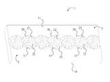
- FIG. 1 is a perspective view of the present invention, showing the helically positioned inner lip within each of the plurality of spiral pockets; the plurality of spiral pockets being linearly positioned across the main body.
- FIG. 2 is a top plan view of the present invention, wherein the upper opening is coplanar with the drafting surface, and the upper opening and the lower face are concentric.
- FIG. 3 is a perspective view of the present invention, wherein the flow redirect groove and the downstream gap are utilized in conjunction with the plurality of spiral pockets.
- FIG. 4 is a top plan view of the present invention, wherein the flow redirect groove and the downstream gap are utilized in conjunction with the plurality of spiral pockets.
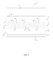
- FIG. 5 is a left side elevational view of the present invention, wherein the flow redirect groove and the downstream gap are utilized in conjunction with the plurality of spiral pockets.
- FIG. 6 is a top plan view, wherein the present invention is positioned in between adjacent sluice plates.
- the present invention is a sluice plate with spiral pockets that is intended for implementation as a component in a sluice box used to capture and concentrate heavy metal particles, particularly gold or platinum particles between 3 and 10 microns in size, from a flow of processing material such as water containing crushed ores.
- the spiral pockets and other components of the sluice plate induce regions of high and low pressure within the processing material, thereby stratifying the contents of the processing material permitting the separation and sequestration of higher density metals such as gold and platinum.
- the present invention can also be used in conjunction with other components such as drop pans, support buckets, and high banker attachments, stream flares, waterfall heads, or dredge crash boxes, and any other components of a placer mining system which may facilitate the properly conditioned supply of processing material at the proper flow rate for the proper functioning of the sluice plate with spiral pockets, and to avoid cavitation at any point in the flow.
- other components such as drop pans, support buckets, and high banker attachments, stream flares, waterfall heads, or dredge crash boxes, and any other components of a placer mining system which may facilitate the properly conditioned supply of processing material at the proper flow rate for the proper functioning of the sluice plate with spiral pockets, and to avoid cavitation at any point in the flow.
- the present invention comprises a main plate 1 and a plurality of spiral pockets 2 .
- the main plate 1 provides a solid structure over which a mixture such as water and heavy metal particles is passed, while the plurality of spiral pockets 2 is used to the collect heavy metal particles from the mixture.
- the main plate 1 comprises a main body 10 and a drafting surface 11 , wherein the drafting surface 11 overlays the main body 10 , providing the top surface of the main plate 1 over which the mixture is passed.
- the main body 10 is a flat, elongated structure into which the plurality of spiral pockets 2 is positioned, while the drafting surface 11 is a flat surface that is intended to induce a consistent laminar flow of the mixture (i.e. processing material).
- the plurality of spiral pockets 2 is positioned across the main body 10 , wherein each of the plurality of spiral pockets 2 traverses into the main body 10 through the drafting surface 11 . More specifically, the plurality of spiral pockets 2 is positioned between a first lateral edge and a second lateral edge of the main body 10 ; the first lateral edge and the second lateral edge being terminally positioned opposite each other along the main body 10 , forming the sides of the main plate 1 . In the preferred embodiment of the present invention, the plurality of spiral pockets 2 is linearly positioned across the main body 10 .
- the plurality of spiral pockets 2 is arranged across the main body 10 such that each of the plurality of spiral pockets 2 overlaps an adjacent pocket.
- each of the plurality of spiral pockets 2 overlaps an adjacent pocket.
- the plurality of spiral pockets 2 having an arbitrary pocket, a previous pocket, and a subsequent pocket linearly arranged, wherein the arbitrary pocket is positioned in between the previous pocket and the subsequent pocket; the previous pocket overlaps the arbitrary pocket, while the arbitrary pocket overlaps the subsequent.
- the overlapping of the plurality of spiral pockets 2 ensures that heavy metal particles can be extracted from the mixture across the entire length of the main plate 1 .
- each of the plurality of spiral pockets 2 comprises an upper opening 20 , a lower face 21 , a lateral wall 22 , and an inner lip 23 .
- the upper opening 20 for each of the plurality of spiral pockets 2 forms the top of the pocket, wherein the upper opening 20 is coplanar with the drafting surface 11 .
- the upper opening 20 may have any ellipsoid or polygonal geometry including, but not limited to, circular, oval, triangular, or trapezoidal geometry.
- the lower face 21 of each of the plurality of spiral pockets 2 forms the bottom, closed end of the pocket.
- the lower face 21 is parallel to the upper opening 20 , however, in other embodiments of the present invention the lower face 21 may be positioned at an offset angle from the upper opening 20 .
- the lower face 21 may have any ellipsoid or polygonal geometry, including but not limited to, circular, oval, triangular, or trapezoidal geometry. While the geometry of the lower face 21 is the same as the geometry of the upper opening 20 in the preferred embodiment of the present invention, the lower face 21 and the upper opening 20 may have different geometries in other embodiments. In general, the surface area of the upper opening 20 will be greater than the surface area of the lower face 21 , especially when the lower face 21 is flat.
- the upper opening 20 and the lower face 21 are both circular; the lower face 21 being smaller than the upper opening 20 . Furthermore, the upper opening 20 and the lower face 21 are concentric, wherein the center of the upper opening 20 and the center of the lower face 21 are coaxial. In another embodiment of the present invention, the upper opening 20 and the lower face 21 are both trapezoidal; the lower face 21 being smaller than the upper opening 20 . Again, the upper opening 20 and the lower face 21 are concentric, wherein the center of the upper opening 20 and the center of the lower face 21 are coaxial.
- the upper opening 20 and the lower face 21 are terminally positioned along the lateral wall 22 opposite each other.
- the lateral wall 22 is tapered from the upper opening 20 to the lower face 21 and provides the enclosed sides of the pocket for each of the plurality of spiral pockets 2 .
- the inner lip 23 is perimetrically positioned about the lateral wall 22 and helically positioned along the lateral wall 22 from the upper opening 20 to the lower face 21 , wherein the inner lip 23 forms a downward spiraling ramp along the lateral wall 22 . Due to the tapered nature of the lateral wall 22 , the inner lip 23 forms smaller and smaller loops around the lateral wall 22 as the inner lip 23 approaches the lower face 21 .
- the inner lip 23 is continuous along the length of the lateral wall 22 forming a single downward spiraling ramp.
- the inner lip 23 may be separated, wherein gaps are present between one or more sections of the inner lip 23 .
- the inner lip 23 remains helically positioned along the lateral wall 22 , wherein each of the segments adjacent to either side of a gap follow a continuous path.
- the flow of the mixture over the plurality of spiral pockets 2 results in a pressure gradient with low pressure at the upper opening 20 and higher pressure at the lower face 21 , as well as other fluid phenomena affecting the boundary layer characteristics of the flow.
- the flow of the mixture in, around, and over each of the plurality of spiral pockets 2 establishes regions of the mixture within, around, and above each of the plurality of spiral pockets 2 having different flow conditions.
- These resulting pressure gradients, along with the downward, tapered spiral of the inner lip 23 induce a rotating flow of the mixture within each of the plurality of spiral pockets 2 which may appear hydrocyclonic but does not comprise the discrete fluid entry and exit points which define a hydrocyclone.
- each of the plurality of spiral pockets 2 flow is mostly laminar. This fluid can flow over the plurality of spiral pockets 2 without scrubbing out denser materials lower in the plurality of spiral pockets 2 .
- the bottom two thirds of each of the plurality of spiral pockets 2 forms a capture zone. In the capture zones, particles of greater density separate from the flow and are kept in constant motion. This prevents saturation or “loading up” of the vortex pockets. Additionally, heavy metal particles from the mixture are stratified based on relative density with the denser materials at the bottom and the less dense materials at the top. For example, the smaller yet denser gold particles would be layered underneath the less dense yet larger magnetite particles in each of the plurality of spiral pockets 2 . In a standard ‘slot type’ pocket no such stratification is observed.
- the present invention may further include channels and other formations in the main body 10 to influence the flow characteristics of the mixture.
- the present invention may further comprise a flow redirect groove 3 or a downstream gap 4 .
- both the flow redirect groove 3 and the downstream gap 4 are positioned adjacent to the plurality of spiral pockets 2 .
- the flow redirect groove 3 and the downstream gap 4 can be used standalone or in tandem depending on the application of the present invention.
- the plurality of spiral pockets 2 is positioned in between the flow redirect groove 3 and the downstream gap 4 , wherein the flow redirect groove 3 is positioned upstream of the plurality of spiral pockets 2 and the downstream gap 4 is positioned downstream of the plurality of spiral pockets 2 .
- the flow redirect groove 3 is positioned across the main body 10 from the first lateral edge to the second lateral edge.
- the flow redirect groove 3 traverses into the main body 10 through the drafting surface 11 creating an open channel across the main plate 1 .
- the flow redirect groove 3 can be designed to serve many purposes including, but not limited to, preventing the scrubbing out of the plurality of spiral pockets 2 in higher water flow circumstances, encouraging mixing of the constituent elements of the mixture (i.e. processing material), breaking down particles, and separating light and heavy materials. In essence, the flow redirect groove 3 is used to manipulate the consistent laminar flow induced by the drafting surface 11 .
- the flow redirect groove 3 comprises a flat down ramp 30 and a curved up ramp 31 , as depicted in FIG. 3-5 .
- the curved up ramp 31 is positioned adjacent to the plurality of spiral pockets 2
- the flat down ramp 30 is positioned adjacent to the curved up ramp 31 opposite the plurality of spiral pockets 2 .
- the processing material first reaches the flat down ramp 30 , which is a flat surface angled downward from the drafting surface 11 .
- the angled down ramp imparts additional kinetic energy to the flow.
- the processing material reaches the curved up ramp 31 , which is a ramp that deflects the mixture upwards, normal to the drafting surface 11 .
- the processing material then flows from the curved up ramp 31 , over the plurality of spiral pockets 2 .
- the downstream gap 4 is positioned across the main body 10 from the first lateral edge to the second lateral edge.
- the downstream gap 4 traverses into the main body 10 through the drafting surface 11 creating an open channel across the main plate 1 .
- the downstream gap 4 is a trough between an adjacent, downstream sluice plate.
- the downstream gap 4 may serve many purposes including buffering the flow to inhibit users from scrubbing out the plurality of spiral pockets 2 by over pouring processing material into the sluice box, capturing refuse materials such as magnetite from the flow, breaking down particles, and separating light and heavy material. After exiting the downstream gap 4 , the processing material may then flow over the adjacent sluice plate.
- the downstream gap 4 comprises a chamfer 40 and a horizontal channel 41 , as depicted in FIG. 3-5 .
- the chamfer 40 is positioned adjacent to the plurality of spiral pockets 2
- the horizontal channel 41 is positioned adjacent to the chamfer 40 opposite the plurality of spiral pockets 2 .
- the chamfer 40 is a flat surface which is angled downward from the drafting surface 11 .
- the chamfer 40 guides the processing material that has flowed over the plurality of spiral pockets 2 into the horizontal channel 41 heavy metal particles are further collected. The processing material then continues to flow out of the horizontal channel 41 and over the adjacent sluice plate.
Landscapes
- Separation Of Solids By Using Liquids Or Pneumatic Power (AREA)
Abstract
Description
Claims (19)
Priority Applications (1)
| Application Number | Priority Date | Filing Date | Title |
|---|---|---|---|
| US14/852,328 US9511376B2 (en) | 2014-09-11 | 2015-09-11 | Sluice plate with spiral pockets |
Applications Claiming Priority (2)
| Application Number | Priority Date | Filing Date | Title |
|---|---|---|---|
| US201462049269P | 2014-09-11 | 2014-09-11 | |
| US14/852,328 US9511376B2 (en) | 2014-09-11 | 2015-09-11 | Sluice plate with spiral pockets |
Publications (2)
| Publication Number | Publication Date |
|---|---|
| US20160074871A1 US20160074871A1 (en) | 2016-03-17 |
| US9511376B2 true US9511376B2 (en) | 2016-12-06 |
Family
ID=55453860
Family Applications (1)
| Application Number | Title | Priority Date | Filing Date |
|---|---|---|---|
| US14/852,328 Active US9511376B2 (en) | 2014-09-11 | 2015-09-11 | Sluice plate with spiral pockets |
Country Status (1)
| Country | Link |
|---|---|
| US (1) | US9511376B2 (en) |
Citations (5)
| Publication number | Priority date | Publication date | Assignee | Title |
|---|---|---|---|---|
| US2100262A (en) * | 1936-02-29 | 1937-11-23 | Moorhead Albert Lee | Sluice box and amalgamation concentrator |
| US4592833A (en) * | 1984-01-16 | 1986-06-03 | Vernon Perdue | Portable sluice box |
| US5927509A (en) * | 1997-09-19 | 1999-07-27 | Lord; Jerome | Gold separation kit |
| US7892847B2 (en) * | 2002-04-05 | 2011-02-22 | The United States Of America As Represented By The Department Of Health And Human Services | Method and apparatus for countercurrent chromatography |
| US8678192B1 (en) * | 2010-10-27 | 2014-03-25 | Michael Pung | Gold cube |
-
2015
- 2015-09-11 US US14/852,328 patent/US9511376B2/en active Active
Patent Citations (5)
| Publication number | Priority date | Publication date | Assignee | Title |
|---|---|---|---|---|
| US2100262A (en) * | 1936-02-29 | 1937-11-23 | Moorhead Albert Lee | Sluice box and amalgamation concentrator |
| US4592833A (en) * | 1984-01-16 | 1986-06-03 | Vernon Perdue | Portable sluice box |
| US5927509A (en) * | 1997-09-19 | 1999-07-27 | Lord; Jerome | Gold separation kit |
| US7892847B2 (en) * | 2002-04-05 | 2011-02-22 | The United States Of America As Represented By The Department Of Health And Human Services | Method and apparatus for countercurrent chromatography |
| US8678192B1 (en) * | 2010-10-27 | 2014-03-25 | Michael Pung | Gold cube |
Also Published As
| Publication number | Publication date |
|---|---|
| US20160074871A1 (en) | 2016-03-17 |
Similar Documents
| Publication | Publication Date | Title |
|---|---|---|
| Majumder et al. | Modeling of enhanced gravity concentrators–present status | |
| Bazin et al. | Size recovery curves of minerals in industrial spirals for processing iron oxide ores | |
| Galvin et al. | Single-stage recovery and concentration of mineral sands using a reflux™ classifier | |
| Jain | An analytical approach to explain complex flow in spiral concentrator and development of flow equations | |
| WO2008070182A1 (en) | Dense medium separator | |
| Sadeghi et al. | Radial distribution of iron oxide and silica particles in the reject flow of a spiral concentrator | |
| US20070163926A1 (en) | Method and device for separating solid particles on the basis of a difference in density | |
| US9511376B2 (en) | Sluice plate with spiral pockets | |
| US20130001138A1 (en) | Particle Classifier Apparatus | |
| US20240066437A1 (en) | Detection and recovery of metals from ore | |
| US20180093277A1 (en) | Louvered Sluice | |
| US20210260625A1 (en) | Sizing and separating granular particles | |
| Jambal et al. | Physical separation using an autogenous medium on coal | |
| Shekhar et al. | Study of process efficiency for high-ash fine coal cleaning in a Kelsey centrifugal jig | |
| He et al. | Research progress of supergravity technology and its application in mineral separation | |
| US9586211B2 (en) | Kreeger sluice | |
| RU2490068C2 (en) | Method of dressing of iron ore | |
| RU178512U1 (en) | Separate mini-prefix | |
| RU2601345C1 (en) | Method for gravity extraction of fine and thin gold and system for gold extraction | |
| RU2160164C1 (en) | Plant for recovery of fine gold | |
| US9168536B2 (en) | Vertical vortex generating sluice/slurry separator | |
| US1004412A (en) | Ore-concentrator. | |
| CN101102849B (en) | Sluice for the deposition of heavy mineral concentrates from mineral slurries and collecting felt therefor | |
| RU2245740C1 (en) | Method of heavy metals deposits ore dressing | |
| RU2385771C1 (en) | Thin-layer separator of polymineral hydraulic suspension |
Legal Events
| Date | Code | Title | Description |
|---|---|---|---|
| STCF | Information on status: patent grant |
Free format text: PATENTED CASE |
|
| AS | Assignment |
Owner name: BURSEY, JOSEPH HUNTER, MASSACHUSETTS Free format text: ASSIGNMENT OF ASSIGNORS INTEREST;ASSIGNOR:MAKOWSKI, BERNARD;REEL/FRAME:051492/0372 Effective date: 20200109 |
|
| FEPP | Fee payment procedure |
Free format text: MAINTENANCE FEE REMINDER MAILED (ORIGINAL EVENT CODE: REM.); ENTITY STATUS OF PATENT OWNER: MICROENTITY |
|
| FEPP | Fee payment procedure |
Free format text: SURCHARGE FOR LATE PAYMENT, MICRO ENTITY (ORIGINAL EVENT CODE: M3554); ENTITY STATUS OF PATENT OWNER: MICROENTITY |
|
| MAFP | Maintenance fee payment |
Free format text: PAYMENT OF MAINTENANCE FEE, 4TH YEAR, MICRO ENTITY (ORIGINAL EVENT CODE: M3551); ENTITY STATUS OF PATENT OWNER: MICROENTITY Year of fee payment: 4 |
|
| FEPP | Fee payment procedure |
Free format text: MAINTENANCE FEE REMINDER MAILED (ORIGINAL EVENT CODE: REM.); ENTITY STATUS OF PATENT OWNER: MICROENTITY |
|
| FEPP | Fee payment procedure |
Free format text: SURCHARGE FOR LATE PAYMENT, MICRO ENTITY (ORIGINAL EVENT CODE: M3555); ENTITY STATUS OF PATENT OWNER: MICROENTITY |
|
| MAFP | Maintenance fee payment |
Free format text: PAYMENT OF MAINTENANCE FEE, 8TH YEAR, MICRO ENTITY (ORIGINAL EVENT CODE: M3552); ENTITY STATUS OF PATENT OWNER: MICROENTITY Year of fee payment: 8 |