US9508652B1 - Direct IC-to-package wafer level packaging with integrated thermal heat spreaders - Google Patents
Direct IC-to-package wafer level packaging with integrated thermal heat spreaders Download PDFInfo
- Publication number
- US9508652B1 US9508652B1 US14/950,667 US201514950667A US9508652B1 US 9508652 B1 US9508652 B1 US 9508652B1 US 201514950667 A US201514950667 A US 201514950667A US 9508652 B1 US9508652 B1 US 9508652B1
- Authority
- US
- United States
- Prior art keywords
- wafer
- plated
- cover wafer
- cover
- die
- Prior art date
- Legal status (The legal status is an assumption and is not a legal conclusion. Google has not performed a legal analysis and makes no representation as to the accuracy of the status listed.)
- Active
Links
Images


Classifications
-
- H01L23/5389—
-
- H—ELECTRICITY
- H10—SEMICONDUCTOR DEVICES; ELECTRIC SOLID-STATE DEVICES NOT OTHERWISE PROVIDED FOR
- H10W—GENERIC PACKAGES, INTERCONNECTIONS, CONNECTORS OR OTHER CONSTRUCTIONAL DETAILS OF DEVICES COVERED BY CLASS H10
- H10W70/00—Package substrates; Interposers; Redistribution layers [RDL]
- H10W70/60—Insulating or insulated package substrates; Interposers; Redistribution layers
- H10W70/611—Insulating or insulated package substrates; Interposers; Redistribution layers for connecting multiple chips together
- H10W70/614—Insulating or insulated package substrates; Interposers; Redistribution layers for connecting multiple chips together the multiple chips being integrally enclosed
-
- H01L21/78—
-
- H01L23/367—
-
- H01L23/40—
-
- H01L24/11—
-
- H01L24/16—
-
- H—ELECTRICITY
- H10—SEMICONDUCTOR DEVICES; ELECTRIC SOLID-STATE DEVICES NOT OTHERWISE PROVIDED FOR
- H10P—GENERIC PROCESSES OR APPARATUS FOR THE MANUFACTURE OR TREATMENT OF DEVICES COVERED BY CLASS H10
- H10P54/00—Cutting or separating of wafers, substrates or parts of devices
-
- H—ELECTRICITY
- H10—SEMICONDUCTOR DEVICES; ELECTRIC SOLID-STATE DEVICES NOT OTHERWISE PROVIDED FOR
- H10W—GENERIC PACKAGES, INTERCONNECTIONS, CONNECTORS OR OTHER CONSTRUCTIONAL DETAILS OF DEVICES COVERED BY CLASS H10
- H10W40/00—Arrangements for thermal protection or thermal control
- H10W40/20—Arrangements for cooling
- H10W40/22—Arrangements for cooling characterised by their shape, e.g. having conical or cylindrical projections
- H10W40/226—Arrangements for cooling characterised by their shape, e.g. having conical or cylindrical projections characterised by projecting parts, e.g. fins to increase surface area
- H10W40/228—Arrangements for cooling characterised by their shape, e.g. having conical or cylindrical projections characterised by projecting parts, e.g. fins to increase surface area the projecting parts being wire-shaped or pin-shaped
-
- H—ELECTRICITY
- H10—SEMICONDUCTOR DEVICES; ELECTRIC SOLID-STATE DEVICES NOT OTHERWISE PROVIDED FOR
- H10W—GENERIC PACKAGES, INTERCONNECTIONS, CONNECTORS OR OTHER CONSTRUCTIONAL DETAILS OF DEVICES COVERED BY CLASS H10
- H10W40/00—Arrangements for thermal protection or thermal control
- H10W40/60—Securing means for detachable heating or cooling arrangements, e.g. clamps
-
- H—ELECTRICITY
- H10—SEMICONDUCTOR DEVICES; ELECTRIC SOLID-STATE DEVICES NOT OTHERWISE PROVIDED FOR
- H10W—GENERIC PACKAGES, INTERCONNECTIONS, CONNECTORS OR OTHER CONSTRUCTIONAL DETAILS OF DEVICES COVERED BY CLASS H10
- H10W44/00—Electrical arrangements for controlling or matching impedance
- H10W44/20—Electrical arrangements for controlling or matching impedance at high-frequency [HF] or radio frequency [RF]
-
- H—ELECTRICITY
- H10—SEMICONDUCTOR DEVICES; ELECTRIC SOLID-STATE DEVICES NOT OTHERWISE PROVIDED FOR
- H10W—GENERIC PACKAGES, INTERCONNECTIONS, CONNECTORS OR OTHER CONSTRUCTIONAL DETAILS OF DEVICES COVERED BY CLASS H10
- H10W76/00—Containers; Fillings or auxiliary members therefor; Seals
- H10W76/10—Containers or parts thereof
- H10W76/12—Containers or parts thereof characterised by their shape
-
- H—ELECTRICITY
- H10—SEMICONDUCTOR DEVICES; ELECTRIC SOLID-STATE DEVICES NOT OTHERWISE PROVIDED FOR
- H10W—GENERIC PACKAGES, INTERCONNECTIONS, CONNECTORS OR OTHER CONSTRUCTIONAL DETAILS OF DEVICES COVERED BY CLASS H10
- H10W76/00—Containers; Fillings or auxiliary members therefor; Seals
- H10W76/60—Seals
-
- H01L2223/6644—
-
- H01L2924/15—
-
- H—ELECTRICITY
- H10—SEMICONDUCTOR DEVICES; ELECTRIC SOLID-STATE DEVICES NOT OTHERWISE PROVIDED FOR
- H10W—GENERIC PACKAGES, INTERCONNECTIONS, CONNECTORS OR OTHER CONSTRUCTIONAL DETAILS OF DEVICES COVERED BY CLASS H10
- H10W44/00—Electrical arrangements for controlling or matching impedance
- H10W44/20—Electrical arrangements for controlling or matching impedance at high-frequency [HF] or radio frequency [RF]
- H10W44/203—Electrical connections
- H10W44/216—Waveguides, e.g. strip lines
-
- H—ELECTRICITY
- H10—SEMICONDUCTOR DEVICES; ELECTRIC SOLID-STATE DEVICES NOT OTHERWISE PROVIDED FOR
- H10W—GENERIC PACKAGES, INTERCONNECTIONS, CONNECTORS OR OTHER CONSTRUCTIONAL DETAILS OF DEVICES COVERED BY CLASS H10
- H10W44/00—Electrical arrangements for controlling or matching impedance
- H10W44/20—Electrical arrangements for controlling or matching impedance at high-frequency [HF] or radio frequency [RF]
- H10W44/226—Electrical arrangements for controlling or matching impedance at high-frequency [HF] or radio frequency [RF] for HF amplifiers
-
- H—ELECTRICITY
- H10—SEMICONDUCTOR DEVICES; ELECTRIC SOLID-STATE DEVICES NOT OTHERWISE PROVIDED FOR
- H10W—GENERIC PACKAGES, INTERCONNECTIONS, CONNECTORS OR OTHER CONSTRUCTIONAL DETAILS OF DEVICES COVERED BY CLASS H10
- H10W44/00—Electrical arrangements for controlling or matching impedance
- H10W44/20—Electrical arrangements for controlling or matching impedance at high-frequency [HF] or radio frequency [RF]
- H10W44/251—Electrical arrangements for controlling or matching impedance at high-frequency [HF] or radio frequency [RF] for monolithic microwave integrated circuits [MMIC]
-
- H—ELECTRICITY
- H10—SEMICONDUCTOR DEVICES; ELECTRIC SOLID-STATE DEVICES NOT OTHERWISE PROVIDED FOR
- H10W—GENERIC PACKAGES, INTERCONNECTIONS, CONNECTORS OR OTHER CONSTRUCTIONAL DETAILS OF DEVICES COVERED BY CLASS H10
- H10W72/00—Interconnections or connectors in packages
- H10W72/01—Manufacture or treatment
- H10W72/012—Manufacture or treatment of bump connectors, dummy bumps or thermal bumps
- H10W72/01231—Manufacture or treatment of bump connectors, dummy bumps or thermal bumps using blanket deposition
- H10W72/01233—Manufacture or treatment of bump connectors, dummy bumps or thermal bumps using blanket deposition in liquid form, e.g. spin coating, spray coating or immersion coating
- H10W72/01235—Manufacture or treatment of bump connectors, dummy bumps or thermal bumps using blanket deposition in liquid form, e.g. spin coating, spray coating or immersion coating by plating, e.g. electroless plating or electroplating
-
- H—ELECTRICITY
- H10—SEMICONDUCTOR DEVICES; ELECTRIC SOLID-STATE DEVICES NOT OTHERWISE PROVIDED FOR
- H10W—GENERIC PACKAGES, INTERCONNECTIONS, CONNECTORS OR OTHER CONSTRUCTIONAL DETAILS OF DEVICES COVERED BY CLASS H10
- H10W72/00—Interconnections or connectors in packages
- H10W72/01—Manufacture or treatment
- H10W72/016—Manufacture or treatment of strap connectors
-
- H—ELECTRICITY
- H10—SEMICONDUCTOR DEVICES; ELECTRIC SOLID-STATE DEVICES NOT OTHERWISE PROVIDED FOR
- H10W—GENERIC PACKAGES, INTERCONNECTIONS, CONNECTORS OR OTHER CONSTRUCTIONAL DETAILS OF DEVICES COVERED BY CLASS H10
- H10W72/00—Interconnections or connectors in packages
- H10W72/01—Manufacture or treatment
- H10W72/0198—Manufacture or treatment batch processes
-
- H—ELECTRICITY
- H10—SEMICONDUCTOR DEVICES; ELECTRIC SOLID-STATE DEVICES NOT OTHERWISE PROVIDED FOR
- H10W—GENERIC PACKAGES, INTERCONNECTIONS, CONNECTORS OR OTHER CONSTRUCTIONAL DETAILS OF DEVICES COVERED BY CLASS H10
- H10W72/00—Interconnections or connectors in packages
- H10W72/071—Connecting or disconnecting
- H10W72/072—Connecting or disconnecting of bump connectors
- H10W72/07221—Aligning
- H10W72/07223—Active alignment, e.g. using optical alignment using marks or sensors
-
- H—ELECTRICITY
- H10—SEMICONDUCTOR DEVICES; ELECTRIC SOLID-STATE DEVICES NOT OTHERWISE PROVIDED FOR
- H10W—GENERIC PACKAGES, INTERCONNECTIONS, CONNECTORS OR OTHER CONSTRUCTIONAL DETAILS OF DEVICES COVERED BY CLASS H10
- H10W72/00—Interconnections or connectors in packages
- H10W72/071—Connecting or disconnecting
- H10W72/072—Connecting or disconnecting of bump connectors
- H10W72/07231—Techniques
- H10W72/07232—Compression bonding, e.g. thermocompression bonding
-
- H—ELECTRICITY
- H10—SEMICONDUCTOR DEVICES; ELECTRIC SOLID-STATE DEVICES NOT OTHERWISE PROVIDED FOR
- H10W—GENERIC PACKAGES, INTERCONNECTIONS, CONNECTORS OR OTHER CONSTRUCTIONAL DETAILS OF DEVICES COVERED BY CLASS H10
- H10W72/00—Interconnections or connectors in packages
- H10W72/071—Connecting or disconnecting
- H10W72/072—Connecting or disconnecting of bump connectors
- H10W72/07231—Techniques
- H10W72/07236—Soldering or alloying
-
- H—ELECTRICITY
- H10—SEMICONDUCTOR DEVICES; ELECTRIC SOLID-STATE DEVICES NOT OTHERWISE PROVIDED FOR
- H10W—GENERIC PACKAGES, INTERCONNECTIONS, CONNECTORS OR OTHER CONSTRUCTIONAL DETAILS OF DEVICES COVERED BY CLASS H10
- H10W72/00—Interconnections or connectors in packages
- H10W72/071—Connecting or disconnecting
- H10W72/073—Connecting or disconnecting of die-attach connectors
-
- H—ELECTRICITY
- H10—SEMICONDUCTOR DEVICES; ELECTRIC SOLID-STATE DEVICES NOT OTHERWISE PROVIDED FOR
- H10W—GENERIC PACKAGES, INTERCONNECTIONS, CONNECTORS OR OTHER CONSTRUCTIONAL DETAILS OF DEVICES COVERED BY CLASS H10
- H10W72/00—Interconnections or connectors in packages
- H10W72/20—Bump connectors, e.g. solder bumps or copper pillars; Dummy bumps; Thermal bumps
- H10W72/221—Structures or relative sizes
- H10W72/222—Multilayered bumps, e.g. a coating on top and side surfaces of a bump core
-
- H—ELECTRICITY
- H10—SEMICONDUCTOR DEVICES; ELECTRIC SOLID-STATE DEVICES NOT OTHERWISE PROVIDED FOR
- H10W—GENERIC PACKAGES, INTERCONNECTIONS, CONNECTORS OR OTHER CONSTRUCTIONAL DETAILS OF DEVICES COVERED BY CLASS H10
- H10W72/00—Interconnections or connectors in packages
- H10W72/20—Bump connectors, e.g. solder bumps or copper pillars; Dummy bumps; Thermal bumps
- H10W72/251—Materials
- H10W72/252—Materials comprising solid metals or solid metalloids, e.g. PbSn, Ag or Cu
-
- H—ELECTRICITY
- H10—SEMICONDUCTOR DEVICES; ELECTRIC SOLID-STATE DEVICES NOT OTHERWISE PROVIDED FOR
- H10W—GENERIC PACKAGES, INTERCONNECTIONS, CONNECTORS OR OTHER CONSTRUCTIONAL DETAILS OF DEVICES COVERED BY CLASS H10
- H10W72/00—Interconnections or connectors in packages
- H10W72/851—Dispositions of multiple connectors or interconnections
- H10W72/874—On different surfaces
- H10W72/877—Bump connectors and die-attach connectors
-
- H—ELECTRICITY
- H10—SEMICONDUCTOR DEVICES; ELECTRIC SOLID-STATE DEVICES NOT OTHERWISE PROVIDED FOR
- H10W—GENERIC PACKAGES, INTERCONNECTIONS, CONNECTORS OR OTHER CONSTRUCTIONAL DETAILS OF DEVICES COVERED BY CLASS H10
- H10W90/00—Package configurations
- H10W90/701—Package configurations characterised by the relative positions of pads or connectors relative to package parts
- H10W90/721—Package configurations characterised by the relative positions of pads or connectors relative to package parts of bump connectors
- H10W90/724—Package configurations characterised by the relative positions of pads or connectors relative to package parts of bump connectors between a chip and a stacked insulating package substrate, interposer or RDL
Definitions
- This disclosure relates to wafer-level packaging for integrated circuits and methods for making wafer-level packages for integrated circuits.
- a Margomenos, et al describe in U.S. Pat. No. 8,617,927, issued Dec. 31, 2013, a surface mount package for GaN devices with embedded heat spreaders.
- A. Margomenos, et al also describe packaging, methods in “Novel Packaging, Cooling and Interconnection Method for GaN High Performance Power Amplifiers and GaN based RF Front-Ends” European Microwave Conference 2012, which is incorporated herein by reference.
- A. Margomenos, et al describe thermal management for power amplifiers in “X-Band Highly Efficient GaN Power Amplifier Utilizing Built-In Electroformed Heat Sinks for Advanced Thermal Management”, IEEE International Microwave Symposium 2013, which is incorporated herein by reference. The above A.
- Margomenos references present cooling packaging and interconnection methods for wide band gap devices.
- the interconnection methods rely on wire bonds or electroplated interconnects to connect the microelectronic chips to the packaging. These interconnection methods result in direct current (DC) and radio frequency (RF) losses, increased cost, and increased package volume over what is desirable.
- the microelectronic chips namely, GaN on SiC monolithic microwave integrated circuits (MMICs)
- MMICs monolithic microwave integrated circuits
- additional processing steps for packaging compatibility such as processing steps for adding benzocyclobutene (BCB) layers.
- Such steps add high-frequency losses due to increased parasitic capacitances due to the dielectric constant of BCB.
- BCB benzocyclobutene
- a method for wafer level packaging comprises forming one or more die, forming a plated metal ring on each die, forming a cover wafer, the cover wafer having one or more plated seal rings, forming a body wafer, the body wafer having cavities and a metal layer on a first side of the body wafer, aligning a respective die to the cover wafer so that a plated metal ring on the respective die is aligned to a respective plated seal ring on the cover wafer, bonding the plated metal ring on the respective die to the respective plated seal ring, aligning the body wafer to the cover wafer so that a respective cavity of the body wafer surrounds each respective die bonded to the cover wafer and so that the metal layer on the body wafer is aligned with at least one plated seal ring on the cover wafer, and bonding the metal layer on the first side of the body wafer to the plated seal ring on the cover wafer, wherein each plated metal ring has
- a wafer level package comprises one or more die, a plated metal ring on each die, a cover wafer, the cover wafer having one or more plated seal rings, wherein the plated metal ring on a respective die is bonded to a respective plated seal ring, and a body wafer, the body wafer having cavities and a metal layer on a first side of the body wafer, wherein the metal layer on the first side of the body wafer is bonded to the plated seal ring on the cover wafer, and wherein each respective cavity surrounds respective die, wherein each plated metal ring has a first height and each plated seal ring has a second height.
- a method for wafer level packaging comprises forming an integrated circuit wafer having a plurality of circuit regions, forming a plurality of plated metal rings, each plated metal ring surrounding a respective circuit regions, forming a cover wafer, the cover wafer having one or more plated seal rings and one or more cavities, forming a body wafer, the body wafer having cavities and a metal layer on a first side of the body wafer, aligning the integrated circuit wafer to the cover wafer so that a plated metal ring on each respective circuit region is aligned to a respective plated seal ring on the cover wafer, and so that each circuit region is aligned to a respective cavity in the cover wafer, bonding the plurality of plated metal rings to the respective aligned plated seal rings using thermocompression bonding, aligning the body wafer to the integrated circuit wafer so that each respective cavity of the body wafer is aligned with each respective circuit region, and bonding the body wafer to the integrated circuit wafer using thermocom
- FIG. 1 is a schematic showing a die, which may be a MMIC, with a double-plated sealing ring and double-plated electrical bumps in accordance with the present disclosure
- FIG. 2 shows a schematic showing a cross section of a cover wafer in accordance with the present disclosure
- FIG. 3A shows a model
- FIG. 3B shows the parameters of the model
- FIG. 3C shows the results of a HFSS model in accordance with the present disclosure
- FIG. 4A shows a body wafer
- FIG. 4B shows a cross section of FIG. 4A in accordance with the present disclosure
- FIG. 5 shows a cross-sectional schematic showing a cover wafer with bonded integrated circuit (IC) dice in accordance with the present disclosure
- FIG. 6 shows a cross-sectional schematic showing a cover wafer with bonded IC dice and sputtered Ti/Au layer stack for heat spreader electroforming in accordance with the present disclosure
- FIG. 7A shows a cover wafer bonded to an IC dice and a body wafer bonded to the cover wafer
- FIG. 7B shows half-way through electroform plating of a heat sink
- FIG. 7C shows after a plating step is completed showing over-plating
- FIG. 7D shows after chemical-mechanical planarization in accordance with the present disclosure
- FIG. 8 shows a cross-sectional schematic showing wafer-level packages for IC dice with integrated heat spreaders capped with Au passivation in accordance with the present disclosure
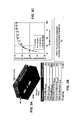
- FIGS. 9A and 9B show diced packages in accordance with the present disclosure.
- FIG. 10 shows a cross-sectional schematic showing wafer-level packaging for IC wafers with integrated heat spreaders in accordance with the present disclosure.
- the present disclosure describes a method to fabricate a wafer-level package for microelectronic circuits having integrated thermal heat spreaders, a hermetic cavity for one or more microelectronic chips, and through-wafer electrical DC and RF interconnects.
- Advanced 3-D interconnect topologies coupled with advanced integrated thermal management are enabled with the present disclosure.
- the present disclosure also provides for wafer-level modules that utilize technologies such as multi-chip stacking, interposers, and wafer-level packaging of integrated circuit (IC) wafers.
- IC integrated circuit
- the present disclosure combines the bonding of known-good microelectronic chips, such as wide band gap semiconductors, such as GaN on SiC, onto a cover wafer with pre-fabricated interconnects to interconnects, a hermetically-sealed cavity for the chips, and integrated thermal heat spreaders in direct contact with the backside of the microelectronic chips for excellent thermal management.
- known-good microelectronic chips such as wide band gap semiconductors, such as GaN on SiC
- wafer-level packaging has used wire-bonding and electroplated interconnects to connect the chips to through-wafer interconnects, and the result is a higher interconnect loss of about 0.4 dB per interconnect at 20 GHz than the packaging of the present disclosure.
- the present disclosure describes a shorter and more cost-effective process compared to the approximately $1 per wire bond cost for the prior art.
- die packaging usually requires die encapsulation using, for example, epoxy or BCB, to protect the dice during the packaging process.
- the present disclosure avoids the disadvantages associated with die encapsulation, and only requires one additional electroplating step in a standard MMIC fabrication sequence.
- known good dice 10 are first picked from a tested wafer, which may be any IC wafer such as GaN-on-SiC, GaAs, InP, CMOS or others known by experts in the field.
- FIG. 1 shows a GaN on SiC die 10 .
- the die 10 may be a MMIC and include one or more transistors 20 on the substrate 12 .
- the transistor 20 shown in FIG. 1 is a HEMT 20 having a gate 22 , a source 24 , and a drain 26 ; however, the transistor 20 may be any other type of transistor including different types of field effect transistors and bipolar transistors.
- the transistor 20 may be connected for electrical grounding to backside metal 14 on the backside of the substrate 12 , by a backside via 16 through the substrate 12 .
- the backside metal 14 may be gold.
- the die 10 may also include one or more circuits on the substrate 12 , such as inductor 40 , resistor 42 , and capacitor 44 .
- the die 10 has a double-plated metal ring 30 , 32 on the edge of the die 10 .
- Metal ring 30 is plated on top of metal ring 32 .
- Each metal ring 30 and 32 may be gold (Au) and each metal ring may be 3 to 5 microns thick.
- the double-plated metal ring 30 , 32 may have a total thickness in the range of 6 to 10 microns, which is high enough to protect air bridge interconnects on the die 10 .
- a thin metal layer 33 which may be Au, may be deposited by sputtering on the substrate 12 to initiate the plating of metal ring 32 .
- the die 10 also has double-plated bumps 34 , 36 .
- Bump 34 is plated on top of bump 36 .
- Each bump 34 and 36 may be gold (Au) and each bump may be 3 to 5 microns thick.
- the double-plated bump 34 , 36 may have a total thickness in the range of 6 to 10 microns.
- the double-plated bumps 34 , 36 are used for interconnect.
- double plating is used instead of a single plating, because 5 micron thick plating is standard, and plating a single layer to be 10 microns thick stresses the plating art.
- a single layer metal ring may be used and satisfies the needs of the present disclosure if made a sufficient thickness.
- the thickness of the double-plated metal ring 30 , 32 and the thickness of the double-plated bumps 34 , 36 be uniform or the same across the wafer so that thermocompression die-to-package bonding may be performed at a later stage of the die packaging process.
- the double-plated metal ring 30 , 32 be near a die edge 46 , and in a preferred embodiment, the distance between the die edge 46 and the double-plated metal ring 30 , 32 is less than or equal to 50 microns in order to maximize the extent of the cavity for circuitry within the double-plated metal ring 30 , 32 .
- the width 48 of the double-plated metal ring 30 , 32 can range from 10 to 200 microns and may be typically 50 microns.
- the double-plated metal ring 30 , 32 may be connected for electrical grounding to backside metal 14 , on the backside of the substrate 12 , by a backside via 17 through the substrate 12 in order to reduce or eliminate parasitic capacitive coupling, which otherwise may cause resonance at RF frequencies.
- the double-plated metal ring 30 , 32 has two major advantages. First, the double-plated metal ring 30 , 32 , as explained further below, enables sealing the die within a cavity for hermetically-sealed die packaging, which is desirable for high-reliability chip operation. Second the double-plated metal ring 30 , 32 enables microfabrication of integrated thermal heat spreaders, which are critical for thermal management.
- the double-plated bumps 34 , 36 provide electrical interconnects. In addition, the double-plated bumps 34 , 36 provide additional mechanical support and protection around the die. There is a lateral gap 50 between the double-plated metal ring 30 , 32 and the double-plated bumps 34 , 36 . It is preferable that the lateral gap 50 be at least 100 microns to eliminate parasitic capacitive coupling.
- FIG. 2 shows a cover wafer 60 in accordance with the present disclosure.
- the cover wafer 60 may be high-resistivity silicon, quartz, glass, silicon carbide or other materials.
- the cover wafer 60 contains one or more cavities 61 .
- Through wafer electrical interconnects 70 may be included, and the interconnects 70 may be copper-filled.
- the through wafer via for the wafer electrical interconnects 70 is coated first with one or more diffusion barrier layers, which may be Ta, TaN, TiN or SiO 2 to prevent copper diffusion into the cover wafer 60 .
- the through wafer electrical interconnects 70 may be connected to topside circuitry 72 for radio frequency (RF) and direct current (DC) interconnects.
- RF radio frequency
- DC direct current
- the topside circuitry may be any combination of active, such as transistors, and passive electronic components, such as resistors, capacitors or inductors, or may be only an interconnect for RF or DC inputs or outputs.
- On the cover wafer 60 are bottom side double-plated sealing rings 62 , 64 and bottom side double-plated bumps 66 , 68 .
- the double-plated sealing rings 62 , 64 and the double-plated bumps 66 , 68 are critical, not only to package the IC die and enable interconnects and heat spreader integration, but also to mitigate effects of potential parasitic capacitive coupling from the cover wafer 60 to the IC die 10 , therefore enabling high-performance operation.
- FIG. 2 shows a cross-sectional schematic of a cover wafer 60 with two cavities 61 .
- a high-resistivity silicon cover wafer 60 may be used and have a thickness of 150 microns or less.
- the cavities 61 preferably have a depth 74 on the order of 75 microns.
- FIG. 3A shows a model and FIG. 3B shows the parameters of the model for deriving requirements on the cavity in the silicon cover wafer.
- FIG. 3C shows the results of a HFSS model where the characteristic impedance of a coplanar waveguide (CPW) transmission line was modeled as a function of the air gap between the surface of the CPW and a silicon wafer.
- CPW coplanar waveguide
- FIG. 4A shows a body wafer 80
- FIG. 4B shows a cross section of FIG. 4A in accordance with the present disclosure.
- the body wafer 80 may be high-resistivity silicon, quartz, glass, silicon carbide or other materials.
- the body wafer 80 is made of the same material as the cover wafer 60 , so that the coefficients of temperature are matched.
- the thickness of the body wafer 80 is dependent on the die 10 thickness, which for example may be 50 to 60 microns.
- the substrate 12 may be 50 microns and the height of the double plated rings 30 , 32 may be 10 microns for a total thickness of 60 microns.
- the body wafer 10 thickness needs to be at least of the same thickness as the die 10 thickness, as is evident in FIGS. 7B, 7C, and 7D , and preferably at least twice as thick as the die 10 thickness to provide thermal management.
- cavities 86 in the body wafer 10 may be etched using silicon deep reactive ion etching.
- the size of the cavities 86 is dependent on the dimension of the die 10 , and should be larger than the die 10 by at least 5 microns on each edge of the cavity 86 , and may be 200 microns or larger on each edge.
- the body wafer 80 is oxidized using thermal oxidation.
- the oxide may be SiO 2 and be approximately 0.5 micron thick, though it can range from 0.1 to 5 microns.
- a Ti layer 84 is evaporated on one side of the wafer and an Au layer 82 is evaporated on the Ti layer 84 .
- the thicknesses of the evaporated layers may be on the order of 300 A and 10,000 A for the Ti layer 84 and for the Au 82 layer, respectively.
- the cover wafer, the body wafer, and the die 10 all feature alignment marks to maintain alignment accuracy better than 5 microns for the die 10 to cover wafer 60 bonding and better than 10 microns for the cover wafer 60 to body wafer 80 bonding.
- the next step consists of bonding the die 10 to the cover wafer 60 using gold-to-gold thermocompression bonding. Temperatures ranging from 200 C to 300 C, forces ranging from 2 to 10 Kg, and bonding times on the order of 5 minutes may be used to achieve good electrical and mechanical bonds.
- a high-accuracy die bonder SET FC300 can be utilized for this step, and it is preferable to perform this step under controlled (e.g., inert gas) atmosphere.
- the double-plated metal rings 30 , 32 and the double-plated sealing rings 62 , 64 are bonded together using thermocompression bonding to form hermetically-sealed cavities, while the double-plated bumps 34 , 36 and double-plated bumps 66 , 68 are bonded together using thermocompression bonding to form electrical contacts. It is preferable to offset the double-plated bumps 66 , 68 from the through-cover copper-filled vias, as depicted in FIG. 5 , so that the double-plated bumps 66 , 68 are at least partially directly on the cover wafer 60 .
- thermocompression bonding it is preferable to use thermocompression bonding, other approaches known by experts in the field can also be used such as solder bumps, AuSn bonding, or eutectic bonding.
- the cover wafer 60 is sputtered with a metallic membrane layer 90 , which may be a Ti layer on the order of 500 A thick and an Au layer on the Ti layer with a thicknesses on the order of 3000 A or more.
- This step shown in FIG. 6 , is used to initiate the fabrication of the electroformed heat spreaders.
- the body wafer 80 is aligned and bonded to the cover wafer 90 by thermocompression bonding of the Au in metallic membrane layer 90 to the Au 82 layer on the body wafer 80 , as shown in FIG. 7A .
- the process conditions may be 250 C, 3000 N, and 30 min bond, though this is dependent on the design density.
- the heat spreaders 100 are then electroformed using the body wafer 80 , which may be oxidized high-resistivity silicon, as a plating mold, as depicted in FIGS. 7B and 7C .
- the topside 102 of the cover wafer 60 is protected during electroplating to prevent metal deposition on that surface. Unlike sidewall plating, the bottom-up electroplating of the yields void-free heat spreaders 100 .
- Materials to form the integrated heat spreaders preferably feature high thermal conductivity, and a controllable coefficient of thermal expansion. Examples of such materials are copper, silver, copper alloys, copper-CNT (copper-carbon nanotubes), or other materials known by experts in the field.
- the cavities in the body wafer 80 are over-plated by design, as shown in FIG. 7C .
- the body wafer 80 and the heat spreaders 100 are polished using chemical mechanical planarization (CMP), which may be copper CMP to achieve high planarity, as shown in FIG. 7D .
- CMP chemical mechanical planarization
- a backing layer 110 is deposited and patterned on the heat spreaders 100 to prevent oxidation of the heat spreaders 100 .
- the backing layer 110 may be formed by sputtering a Ti layer on the heat spreaders 100 and sputtering an Au layer on the Ti layer using conventional microfabrication techniques, as shown in FIG. 8 .
- the Ti layer in this and other steps prevents the Au layer from diffusing into the heat spreaders.
- individual packages 120 are diced using laser dicing or mechanical dicing.
- the dicing as shown in FIG. 9 is aligned to be approximately midway through portions of the body wafer 80 between the cavities 86 .
- the result is wafer-level packages 120 for IC dice with integrated heat spreaders and direct die-to-package through-package interconnects.
- the die 10 on an IC wafer 130 are not diced, and the entire IC wafer 130 is directly bonded onto the cover wafer 140 , followed by integration of the body wafer 150 and heat spreader 100 .
- FIG. 10 shows the wafer-level integration. In contrast to the description above where only known good dice are packaged, the wafer-level approach relies on wafer stacking.
- an IC wafer 130 is bonded to a cover wafer 140 by bonding the double-plated metal rings 30 , 32 to the double-plated sealing rings 62 , 64 , and by bonding the double-plated bumps 34 , 36 to the double-plated bumps 66 , 68 using bonding wafer technologies.
- the body wafer 150 is bonded using wafer bonding technologies to the back of the IC wafer 130 .
- the heat spreaders 100 are electroformed in the cavities of the body wafer 150 , which are aligned with regions on the IC wafer 130 that have circuitry.
- the heat spreaders 100 are planarized using CMP, similar to the processes described above.
- a backing layer 110 is deposited and patterned on the heat spreaders 100 to prevent oxidation of the heat spreaders 100 .
- Tests on the present disclosure have been performed. The tests show that the integrated heat spreaders result in an integrated chip performance enhancement up to 40% compared to integrated chips conventionally mounted on heat spreaders. This has been demonstrated by comparing the operating power for a given junction temperature, and a junction temperature for a given operating power.
- the double-plated sealing rings on dice and cover wafers were shown to provide hermetically-sealed packages. This has been demonstrated by submitting these chips to a hermetic seal test (MIL-STD-883, Method 1014) at ORS labs.
- the integrated heat spreaders were shown by X-ray imaging to be void-free for bottom-up copper plating using a high-resistivity silicon wafer as a plating mold.
Landscapes
- Engineering & Computer Science (AREA)
- Manufacturing & Machinery (AREA)
- Wire Bonding (AREA)
Abstract
Description
Claims (20)
Priority Applications (1)
| Application Number | Priority Date | Filing Date | Title |
|---|---|---|---|
| US14/950,667 US9508652B1 (en) | 2015-11-24 | 2015-11-24 | Direct IC-to-package wafer level packaging with integrated thermal heat spreaders |
Applications Claiming Priority (1)
| Application Number | Priority Date | Filing Date | Title |
|---|---|---|---|
| US14/950,667 US9508652B1 (en) | 2015-11-24 | 2015-11-24 | Direct IC-to-package wafer level packaging with integrated thermal heat spreaders |
Publications (1)
| Publication Number | Publication Date |
|---|---|
| US9508652B1 true US9508652B1 (en) | 2016-11-29 |
Family
ID=57351598
Family Applications (1)
| Application Number | Title | Priority Date | Filing Date |
|---|---|---|---|
| US14/950,667 Active US9508652B1 (en) | 2015-11-24 | 2015-11-24 | Direct IC-to-package wafer level packaging with integrated thermal heat spreaders |
Country Status (1)
| Country | Link |
|---|---|
| US (1) | US9508652B1 (en) |
Cited By (20)
| Publication number | Priority date | Publication date | Assignee | Title |
|---|---|---|---|---|
| US9780014B1 (en) | 2011-11-29 | 2017-10-03 | Hrl Laboratories, Llc | Simultaneous controlled depth hot embossing and active side protection during packaging and assembly of wide bandgap devices |
| US9837372B1 (en) | 2015-05-22 | 2017-12-05 | Hrl Laboratories, Llc | Wafer-level die to package and die to die interconnects suspended over integrated heat sinks |
| US10026672B1 (en) * | 2015-10-21 | 2018-07-17 | Hrl Laboratories, Llc | Recursive metal embedded chip assembly |
| US10079160B1 (en) | 2013-06-21 | 2018-09-18 | Hrl Laboratories, Llc | Surface mount package for semiconductor devices with embedded heat spreaders |
| US10950562B1 (en) | 2018-11-30 | 2021-03-16 | Hrl Laboratories, Llc | Impedance-matched through-wafer transition using integrated heat-spreader technology |
| US10957537B2 (en) | 2018-11-12 | 2021-03-23 | Hrl Laboratories, Llc | Methods to design and uniformly co-fabricate small vias and large cavities through a substrate |
| CN112736065A (en) * | 2020-09-10 | 2021-04-30 | 成都芯源系统有限公司 | Panel-shaped metal wall grid array for integrated circuit package and manufacturing method thereof |
| US10998273B2 (en) | 2017-12-22 | 2021-05-04 | Hrl Laboratories, Llc | Hybrid integrated circuit architecture |
| CN113161350A (en) * | 2020-01-22 | 2021-07-23 | 深圳市汇芯通信技术有限公司 | Integrated chip, manufacturing method thereof and integrated circuit |
| US11309412B1 (en) * | 2017-05-17 | 2022-04-19 | Northrop Grumman Systems Corporation | Shifting the pinch-off voltage of an InP high electron mobility transistor with a metal ring |
| US20220223685A1 (en) * | 2021-01-12 | 2022-07-14 | Win Semiconductors Corp. | Semiconductor structure |
| US11527482B2 (en) | 2017-12-22 | 2022-12-13 | Hrl Laboratories, Llc | Hybrid integrated circuit architecture |
| US11533024B2 (en) * | 2020-06-25 | 2022-12-20 | Wolfspeed, Inc. | Multi-zone radio frequency transistor amplifiers |
| US11536800B2 (en) | 2017-12-22 | 2022-12-27 | Hrl Laboratories, Llc | Method and apparatus to increase radar range |
| CN116368614A (en) * | 2020-09-24 | 2023-06-30 | Hrl实验室有限责任公司 | Wafer-level integrated microstructured heat sink |
| US20230317633A1 (en) * | 2022-03-30 | 2023-10-05 | Win Semiconductors Corp. | Semiconductor chip |
| US11917746B2 (en) | 2022-04-22 | 2024-02-27 | Raytheon Company | Low cost panel AESA with thermal management |
| US11972970B1 (en) | 2020-09-01 | 2024-04-30 | Hrl Laboratories, Llc | Singulation process for chiplets |
| US12463109B2 (en) | 2021-10-15 | 2025-11-04 | Hrl Laboratories, Llc | Thermal isolation between embedded MECA modules |
| US12531524B2 (en) | 2020-06-25 | 2026-01-20 | Macom Technology Solutions Holdings, Inc. | Multi-zone radio frequency transistor amplifiers |
Citations (45)
| Publication number | Priority date | Publication date | Assignee | Title |
|---|---|---|---|---|
| US3681513A (en) | 1971-01-26 | 1972-08-01 | American Lava Corp | Hermetic power package |
| US5073521A (en) | 1989-11-15 | 1991-12-17 | Olin Corporation | Method for housing a tape-bonded electronic device and the package employed |
| US5198385A (en) | 1991-01-11 | 1993-03-30 | Harris Corporation | Photolithographic formation of die-to-package airbridge in a semiconductor device |
| US5276455A (en) | 1991-05-24 | 1994-01-04 | The Boeing Company | Packaging architecture for phased arrays |
| US5371404A (en) | 1993-02-04 | 1994-12-06 | Motorola, Inc. | Thermally conductive integrated circuit package with radio frequency shielding |
| US6018459A (en) | 1997-11-17 | 2000-01-25 | Cray Research, Inc. | Porous metal heat sink |
| US6028367A (en) | 1999-05-07 | 2000-02-22 | Taiwan Semiconductor Manufacturing Company, Ltd. | Bonds pads equipped with heat dissipating rings and method for forming |
| US6249439B1 (en) | 1999-10-21 | 2001-06-19 | Hughes Electronics Corporation | Millimeter wave multilayer assembly |
| US20030006499A1 (en) | 1999-05-20 | 2003-01-09 | Hyundai Micro Electronics Co., Ltd. | Semiconductor chip package and method of fabricating same |
| US20050077596A1 (en) | 2003-07-14 | 2005-04-14 | Michael Bauer | Semiconductor component with electromagnetic shielding device |
| US6900765B2 (en) | 2003-07-23 | 2005-05-31 | The Boeing Company | Method and apparatus for forming millimeter wave phased array antenna |
| US20050155752A1 (en) | 2003-11-19 | 2005-07-21 | Larson Ralph I. | Thermal interface and method of making the same |
| US6989592B2 (en) | 2002-05-01 | 2006-01-24 | The Boeing Company | Integrated power module with reduced thermal impedance |
| US20060027635A1 (en) | 2004-08-09 | 2006-02-09 | Schaenzer Matthew J | Thermally coupling an integrated heat spreader to a heat sink base |
| US7015060B1 (en) * | 2004-12-08 | 2006-03-21 | Hrl Laboratories, Llc | Cloverleaf microgyroscope with through-wafer interconnects and method of manufacturing a cloverleaf microgyroscope with through-wafer interconnects |
| US20060091509A1 (en) | 2004-11-03 | 2006-05-04 | Broadcom Corporation | Flip chip package including a non-planar heat spreader and method of making the same |
| US7067397B1 (en) | 2005-06-23 | 2006-06-27 | Northrop Gruman Corp. | Method of fabricating high yield wafer level packages integrating MMIC and MEMS components |
| US20060157223A1 (en) | 2005-01-18 | 2006-07-20 | Gelorme Jeffrey D | Heterogeneous thermal interface for cooling |
| US20060292747A1 (en) | 2005-06-27 | 2006-12-28 | Loh Ban P | Top-surface-mount power light emitter with integral heat sink |
| US20070015666A1 (en) | 2005-03-31 | 2007-01-18 | American Superconductor Corp. | Mesh-type stabilizer for filamentary coated superconductors |
| US20070075420A1 (en) | 2005-09-30 | 2007-04-05 | Intel Corporation | Microelectronic package having direct contact heat spreader and method of manufacturing same |
| US20070247851A1 (en) | 2006-04-21 | 2007-10-25 | Villard Russel G | Light Emitting Diode Lighting Package With Improved Heat Sink |
| US7292381B1 (en) | 2005-09-08 | 2007-11-06 | Hrl Laboratories, Llc | Method for conforming a micro-electronic array to arbitrary shapes |
| US20070290326A1 (en) | 2006-06-19 | 2007-12-20 | Northrop Grumman Space & Missions Systems Corp. | Multi-dimensional wafer-level integrated antenna sensor micro packaging |
| US20080099770A1 (en) | 2006-10-31 | 2008-05-01 | Medendorp Nicholas W | Integrated heat spreaders for light emitting devices (LEDs) and related assemblies |
| US20080128897A1 (en) | 2006-12-05 | 2008-06-05 | Tong Wa Chao | Heat spreader for a multi-chip package |
| US20080179725A1 (en) | 2007-01-30 | 2008-07-31 | Phoenix Precision Technology Corporation | Package structure with circuits directly connected to semiconductor chip |
| US20080298021A1 (en) | 2007-05-31 | 2008-12-04 | Ali Ihab A | Notebook computer with hybrid diamond heat spreader |
| US20090108437A1 (en) | 2007-10-29 | 2009-04-30 | M/A-Com, Inc. | Wafer scale integrated thermal heat spreader |
| US20090134421A1 (en) | 2004-10-25 | 2009-05-28 | Cree, Inc. | Solid metal block semiconductor light emitting device mounting substrates and packages |
| US20090294941A1 (en) | 2008-05-30 | 2009-12-03 | Oh Jihoon | Package-on-package system with heat spreader |
| US20090309209A1 (en) | 2008-06-12 | 2009-12-17 | Yu-Ren Chen | Die Rearrangement Package Structure and the Forming Method Thereof |
| US7733265B2 (en) | 2008-04-04 | 2010-06-08 | Toyota Motor Engineering & Manufacturing North America, Inc. | Three dimensional integrated automotive radars and methods of manufacturing the same |
| US20100140799A1 (en) | 2007-05-04 | 2010-06-10 | Stats Chippac, Ltd. | Extended Redistribution Layers Bumped Wafer |
| US7777315B2 (en) | 2006-05-19 | 2010-08-17 | Fairchild Semiconductor Corporation | Dual side cooling integrated power device module and methods of manufacture |
| US20100283144A1 (en) | 2007-12-26 | 2010-11-11 | Steve Xin Liang | In-situ cavity circuit package |
| US20100327465A1 (en) | 2009-06-25 | 2010-12-30 | Advanced Semiconductor Engineering, Inc. | Package process and package structure |
| US8093690B2 (en) | 2008-10-31 | 2012-01-10 | Advanced Semiconductor Engineering, Inc. | Chip package and manufacturing method thereof |
| US20120217627A1 (en) | 2011-02-24 | 2012-08-30 | Unimicron Technology Corporation | Package structure and method of fabricating the same |
| US8334592B2 (en) | 2007-09-11 | 2012-12-18 | Dow Corning Corporation | Thermal interface material, electronic device containing the thermal interface material, and methods for their preparation and use |
| US8375576B2 (en) | 2005-04-28 | 2013-02-19 | Stats Chippac Ltd. | Method for manufacturing wafer scale heat slug system |
| US8617927B1 (en) | 2011-11-29 | 2013-12-31 | Hrl Laboratories, Llc | Method of mounting electronic chips |
| US8644020B2 (en) | 2010-12-01 | 2014-02-04 | Google Inc. | Cooling heat-generating electronics |
| US20140084445A1 (en) | 2012-09-21 | 2014-03-27 | Taiwan Semiconductor Manufacturing Company, Ltd. | Thermal Dissipation Through Seal Rings in 3DIC Structure |
| US20150007965A1 (en) | 2013-07-05 | 2015-01-08 | Toyota Motor Engineerig & Manufacturing North America, Inc. | Cooling Assemblies Having Porous Three Dimensional Surfaces |
-
2015
- 2015-11-24 US US14/950,667 patent/US9508652B1/en active Active
Patent Citations (51)
| Publication number | Priority date | Publication date | Assignee | Title |
|---|---|---|---|---|
| US3681513A (en) | 1971-01-26 | 1972-08-01 | American Lava Corp | Hermetic power package |
| US5073521A (en) | 1989-11-15 | 1991-12-17 | Olin Corporation | Method for housing a tape-bonded electronic device and the package employed |
| US5198385A (en) | 1991-01-11 | 1993-03-30 | Harris Corporation | Photolithographic formation of die-to-package airbridge in a semiconductor device |
| US5276455A (en) | 1991-05-24 | 1994-01-04 | The Boeing Company | Packaging architecture for phased arrays |
| US5371404A (en) | 1993-02-04 | 1994-12-06 | Motorola, Inc. | Thermally conductive integrated circuit package with radio frequency shielding |
| US6018459A (en) | 1997-11-17 | 2000-01-25 | Cray Research, Inc. | Porous metal heat sink |
| US6028367A (en) | 1999-05-07 | 2000-02-22 | Taiwan Semiconductor Manufacturing Company, Ltd. | Bonds pads equipped with heat dissipating rings and method for forming |
| US20030006499A1 (en) | 1999-05-20 | 2003-01-09 | Hyundai Micro Electronics Co., Ltd. | Semiconductor chip package and method of fabricating same |
| US6249439B1 (en) | 1999-10-21 | 2001-06-19 | Hughes Electronics Corporation | Millimeter wave multilayer assembly |
| US6989592B2 (en) | 2002-05-01 | 2006-01-24 | The Boeing Company | Integrated power module with reduced thermal impedance |
| US20050077596A1 (en) | 2003-07-14 | 2005-04-14 | Michael Bauer | Semiconductor component with electromagnetic shielding device |
| US6900765B2 (en) | 2003-07-23 | 2005-05-31 | The Boeing Company | Method and apparatus for forming millimeter wave phased array antenna |
| US20050155752A1 (en) | 2003-11-19 | 2005-07-21 | Larson Ralph I. | Thermal interface and method of making the same |
| US7364063B2 (en) | 2004-08-09 | 2008-04-29 | Intel Corporation | Thermally coupling an integrated heat spreader to a heat sink base |
| US20060027635A1 (en) | 2004-08-09 | 2006-02-09 | Schaenzer Matthew J | Thermally coupling an integrated heat spreader to a heat sink base |
| US20090134421A1 (en) | 2004-10-25 | 2009-05-28 | Cree, Inc. | Solid metal block semiconductor light emitting device mounting substrates and packages |
| US7271479B2 (en) | 2004-11-03 | 2007-09-18 | Broadcom Corporation | Flip chip package including a non-planar heat spreader and method of making the same |
| US20060091509A1 (en) | 2004-11-03 | 2006-05-04 | Broadcom Corporation | Flip chip package including a non-planar heat spreader and method of making the same |
| US7015060B1 (en) * | 2004-12-08 | 2006-03-21 | Hrl Laboratories, Llc | Cloverleaf microgyroscope with through-wafer interconnects and method of manufacturing a cloverleaf microgyroscope with through-wafer interconnects |
| US20060157223A1 (en) | 2005-01-18 | 2006-07-20 | Gelorme Jeffrey D | Heterogeneous thermal interface for cooling |
| US20070015666A1 (en) | 2005-03-31 | 2007-01-18 | American Superconductor Corp. | Mesh-type stabilizer for filamentary coated superconductors |
| US8375576B2 (en) | 2005-04-28 | 2013-02-19 | Stats Chippac Ltd. | Method for manufacturing wafer scale heat slug system |
| US7067397B1 (en) | 2005-06-23 | 2006-06-27 | Northrop Gruman Corp. | Method of fabricating high yield wafer level packages integrating MMIC and MEMS components |
| US20060292747A1 (en) | 2005-06-27 | 2006-12-28 | Loh Ban P | Top-surface-mount power light emitter with integral heat sink |
| US7292381B1 (en) | 2005-09-08 | 2007-11-06 | Hrl Laboratories, Llc | Method for conforming a micro-electronic array to arbitrary shapes |
| US20070075420A1 (en) | 2005-09-30 | 2007-04-05 | Intel Corporation | Microelectronic package having direct contact heat spreader and method of manufacturing same |
| US20070247851A1 (en) | 2006-04-21 | 2007-10-25 | Villard Russel G | Light Emitting Diode Lighting Package With Improved Heat Sink |
| US7777315B2 (en) | 2006-05-19 | 2010-08-17 | Fairchild Semiconductor Corporation | Dual side cooling integrated power device module and methods of manufacture |
| US20070290326A1 (en) | 2006-06-19 | 2007-12-20 | Northrop Grumman Space & Missions Systems Corp. | Multi-dimensional wafer-level integrated antenna sensor micro packaging |
| US20080099770A1 (en) | 2006-10-31 | 2008-05-01 | Medendorp Nicholas W | Integrated heat spreaders for light emitting devices (LEDs) and related assemblies |
| US7808013B2 (en) | 2006-10-31 | 2010-10-05 | Cree, Inc. | Integrated heat spreaders for light emitting devices (LEDs) and related assemblies |
| US20080128897A1 (en) | 2006-12-05 | 2008-06-05 | Tong Wa Chao | Heat spreader for a multi-chip package |
| US20080179725A1 (en) | 2007-01-30 | 2008-07-31 | Phoenix Precision Technology Corporation | Package structure with circuits directly connected to semiconductor chip |
| US20100140799A1 (en) | 2007-05-04 | 2010-06-10 | Stats Chippac, Ltd. | Extended Redistribution Layers Bumped Wafer |
| US20080298021A1 (en) | 2007-05-31 | 2008-12-04 | Ali Ihab A | Notebook computer with hybrid diamond heat spreader |
| US8334592B2 (en) | 2007-09-11 | 2012-12-18 | Dow Corning Corporation | Thermal interface material, electronic device containing the thermal interface material, and methods for their preparation and use |
| US20090108437A1 (en) | 2007-10-29 | 2009-04-30 | M/A-Com, Inc. | Wafer scale integrated thermal heat spreader |
| US20100283144A1 (en) | 2007-12-26 | 2010-11-11 | Steve Xin Liang | In-situ cavity circuit package |
| US7733265B2 (en) | 2008-04-04 | 2010-06-08 | Toyota Motor Engineering & Manufacturing North America, Inc. | Three dimensional integrated automotive radars and methods of manufacturing the same |
| US7683469B2 (en) | 2008-05-30 | 2010-03-23 | Stats Chippac Ltd. | Package-on-package system with heat spreader |
| US20090294941A1 (en) | 2008-05-30 | 2009-12-03 | Oh Jihoon | Package-on-package system with heat spreader |
| US20090309209A1 (en) | 2008-06-12 | 2009-12-17 | Yu-Ren Chen | Die Rearrangement Package Structure and the Forming Method Thereof |
| US8093690B2 (en) | 2008-10-31 | 2012-01-10 | Advanced Semiconductor Engineering, Inc. | Chip package and manufacturing method thereof |
| US20100327465A1 (en) | 2009-06-25 | 2010-12-30 | Advanced Semiconductor Engineering, Inc. | Package process and package structure |
| US8644020B2 (en) | 2010-12-01 | 2014-02-04 | Google Inc. | Cooling heat-generating electronics |
| US20120217627A1 (en) | 2011-02-24 | 2012-08-30 | Unimicron Technology Corporation | Package structure and method of fabricating the same |
| US8617927B1 (en) | 2011-11-29 | 2013-12-31 | Hrl Laboratories, Llc | Method of mounting electronic chips |
| US9059140B1 (en) | 2011-11-29 | 2015-06-16 | Hrl Laboratories, Llc | Simultaneous controlled depth hot embossing and active side protection during packaging and assembly of wide bandgap devices |
| US9214404B1 (en) | 2011-11-29 | 2015-12-15 | Hrl Laboratories, Llc | Apparatus for mounting microelectronic chips |
| US20140084445A1 (en) | 2012-09-21 | 2014-03-27 | Taiwan Semiconductor Manufacturing Company, Ltd. | Thermal Dissipation Through Seal Rings in 3DIC Structure |
| US20150007965A1 (en) | 2013-07-05 | 2015-01-08 | Toyota Motor Engineerig & Manufacturing North America, Inc. | Cooling Assemblies Having Porous Three Dimensional Surfaces |
Non-Patent Citations (24)
| Title |
|---|
| Chen, K. C., et al., "Thermal Management and Novel Package Design of High Power Light Emitting Diodes," National Cheng Kung University, Taiwan, 2008 Electronic Components and Technology Conference, pp. 795-797, (May 2008). |
| Feeler, R., et al., "Next-Generation Microchannel Coolers," Northrop Grumman, Proceedings of SPIE, vol. 6876, pp. 687608-1-687608-8, (2008). |
| From U.S. Appl. No. 13/306,827 (Now U.S. Pat. No. 8,617,927), Non-Final Rejection mailed on Mar. 7, 2013. |
| From U.S. Appl. No. 13/306,827 (Now U.S. Pat. No. 8,617,927), Notice of Allowance mailed on Aug. 15, 2013. |
| From U.S. Appl. No. 13/306,827 (Now U.S. Pat. No. 8,617,927), Restriction/Election mailed on Jan. 9, 2013. |
| From U.S. Appl. No. 14/054,572 (Now U.S. Pat. No. 9,059,140), Non-Final Rejection mailed on Sep. 19, 2014. |
| From U.S. Appl. No. 14/054,572 (Now U.S. Pat. No. 9,059,140), Notice of Allowance mailed on Feb. 12, 2015. |
| From U.S. Appl. No. 14/054,572 (Now U.S. Pat. No. 9,059,140), Restriction/Election mailed on Jul. 10, 2014. |
| From U.S. Appl. No. 14/080,691 (Now U.S. Pat. No. 9,214,404), Non-Final Rejection mailed on Apr. 16, 2015. |
| From U.S. Appl. No. 14/080,691 (Now U.S. Pat. No. 9,214,404), Notice of Allowance mailed on Aug. 12, 2015. |
| From U.S. Appl. No. 14/080,691 (Now U.S. Pat. No. 9,214,404), Restriction/Election mailed on Dec. 17, 2014. |
| From U.S. Appl. No. 14/286,923, filed May 23, 2014; Unpublished, Non-Publication Requested), Application and Office Actions. |
| From U.S. Appl. No. 14/532,761 (Unpublished, Non-Publication Requested), Non-Final Rejection mailed on Oct. 6, 2015. |
| From U.S. Appl. No. 14/703,545 (Unpublished, Non-Publication Requested), Non-Final Rejection mailed on Dec. 15, 2015. |
| From U.S. Appl. No. 14/720,619 (Unpublished, Non-Publication Requested), Restriction/Election mailed on Sep. 28, 2015. |
| Herrault F. et al., "Silicon-Packaged GaN Power HEMTs with Integrated Heat Spreaders," Electronic Components and Technology Conference (ECTC), 2015 IEEE 65th, Conference: (May 26 to May 29, 2015). |
| Margomenos A. et al., "Novel Packaging, Cooling and Interconnection Method for GaN High Performance Power Amplifiers and GaN Based RF Front-Ends," Proceedings of the 7th European Microwave Integrated Circuits Conference, pp. 615-618, (Oct. 29-30, 2012). |
| Margomenos, A. et al., "Wafer-Level Packaging Method Incorporating Embedded Thermal Management for GaN-Based RF Front-Ends," IEEE Intersociety Conference on Thermal and Thermomechanical Phenomena in Electronic Systems (ITHERM), May 27-30, 2014 in Orlando, Florida. |
| Margomenos, A. et al., "X-Band Highly Efficient GaN Power Amplifier Utilizing Built-In Electroformed Heat Sinks for Advanced Thermal Management," IEEE International Microwave Symposium, pp. 1-4, (Jun. 2-7, 2013). |
| P. Chang-Chien et al., "MMIC Packaging and Heterogeneous Integration Using Wafer-Scale Assembly," CS Mantech Conference, pp. 143-146, (May 14-17, 2007). |
| U.S. Appl. No. 14/286,923, filed May 23, 2014, Margomenos et al. |
| U.S. Appl. No. 14/532,761, filed Nov. 4, 2014, Herrault et al. |
| U.S. Appl. No. 14/703,545, filed May 4, 2015, Margomenos et al. |
| U.S. Appl. No. 14/720,619, filed May 22, 2015, Herrault et al. |
Cited By (25)
| Publication number | Priority date | Publication date | Assignee | Title |
|---|---|---|---|---|
| US9780014B1 (en) | 2011-11-29 | 2017-10-03 | Hrl Laboratories, Llc | Simultaneous controlled depth hot embossing and active side protection during packaging and assembly of wide bandgap devices |
| US10079160B1 (en) | 2013-06-21 | 2018-09-18 | Hrl Laboratories, Llc | Surface mount package for semiconductor devices with embedded heat spreaders |
| US9837372B1 (en) | 2015-05-22 | 2017-12-05 | Hrl Laboratories, Llc | Wafer-level die to package and die to die interconnects suspended over integrated heat sinks |
| US10026672B1 (en) * | 2015-10-21 | 2018-07-17 | Hrl Laboratories, Llc | Recursive metal embedded chip assembly |
| US10483184B1 (en) | 2015-10-21 | 2019-11-19 | Hrl Laboratories, Llc | Recursive metal embedded chip assembly |
| US11309412B1 (en) * | 2017-05-17 | 2022-04-19 | Northrop Grumman Systems Corporation | Shifting the pinch-off voltage of an InP high electron mobility transistor with a metal ring |
| US11536800B2 (en) | 2017-12-22 | 2022-12-27 | Hrl Laboratories, Llc | Method and apparatus to increase radar range |
| US11527482B2 (en) | 2017-12-22 | 2022-12-13 | Hrl Laboratories, Llc | Hybrid integrated circuit architecture |
| US10998273B2 (en) | 2017-12-22 | 2021-05-04 | Hrl Laboratories, Llc | Hybrid integrated circuit architecture |
| US10957537B2 (en) | 2018-11-12 | 2021-03-23 | Hrl Laboratories, Llc | Methods to design and uniformly co-fabricate small vias and large cavities through a substrate |
| US10950562B1 (en) | 2018-11-30 | 2021-03-16 | Hrl Laboratories, Llc | Impedance-matched through-wafer transition using integrated heat-spreader technology |
| CN113161350A (en) * | 2020-01-22 | 2021-07-23 | 深圳市汇芯通信技术有限公司 | Integrated chip, manufacturing method thereof and integrated circuit |
| US12531524B2 (en) | 2020-06-25 | 2026-01-20 | Macom Technology Solutions Holdings, Inc. | Multi-zone radio frequency transistor amplifiers |
| US11533024B2 (en) * | 2020-06-25 | 2022-12-20 | Wolfspeed, Inc. | Multi-zone radio frequency transistor amplifiers |
| US11972970B1 (en) | 2020-09-01 | 2024-04-30 | Hrl Laboratories, Llc | Singulation process for chiplets |
| CN112736065A (en) * | 2020-09-10 | 2021-04-30 | 成都芯源系统有限公司 | Panel-shaped metal wall grid array for integrated circuit package and manufacturing method thereof |
| CN116368614A (en) * | 2020-09-24 | 2023-06-30 | Hrl实验室有限责任公司 | Wafer-level integrated microstructured heat sink |
| US11721605B2 (en) | 2020-09-24 | 2023-08-08 | Hrl Laboratories, Llc | Wafer-level integrated micro-structured heat spreaders |
| CN116368614B (en) * | 2020-09-24 | 2024-05-03 | Hrl实验室有限责任公司 | Wafer level integrated microstructured heat spreader |
| US11695037B2 (en) * | 2021-01-12 | 2023-07-04 | Win Semiconductors Corp. | Semiconductor structure |
| US11967613B2 (en) | 2021-01-12 | 2024-04-23 | Win Semiconductors Corp. | Semiconductor structure |
| US20220223685A1 (en) * | 2021-01-12 | 2022-07-14 | Win Semiconductors Corp. | Semiconductor structure |
| US12463109B2 (en) | 2021-10-15 | 2025-11-04 | Hrl Laboratories, Llc | Thermal isolation between embedded MECA modules |
| US20230317633A1 (en) * | 2022-03-30 | 2023-10-05 | Win Semiconductors Corp. | Semiconductor chip |
| US11917746B2 (en) | 2022-04-22 | 2024-02-27 | Raytheon Company | Low cost panel AESA with thermal management |
Similar Documents
| Publication | Publication Date | Title |
|---|---|---|
| US9508652B1 (en) | Direct IC-to-package wafer level packaging with integrated thermal heat spreaders | |
| US10748825B2 (en) | Package and method for integration of heterogeneous integrated circuits | |
| US10998273B2 (en) | Hybrid integrated circuit architecture | |
| CN102881665B (en) | System and method for wafer level packaging | |
| CN103681636B (en) | Chip is to package interface | |
| KR100851931B1 (en) | Improved interconnect structure for semiconductor package | |
| US11158520B2 (en) | Method to protect die during metal-embedded chip assembly (MECA) process | |
| US20170040296A1 (en) | Multi-Layer Semiconductor Devices Fabricated Using a Combination of Substrate and Via Structures and Fabrication Techniques | |
| US20090176348A1 (en) | Removable layer manufacturing method | |
| WO2017029822A1 (en) | Semiconductor device | |
| JP5813552B2 (en) | Semiconductor package and manufacturing method thereof | |
| KR20160115861A (en) | Substrate interposer on a leadframe | |
| JP2003528469A (en) | Die attachment and method | |
| CN108807197B (en) | Chip package with sidewall metallization | |
| TW201445687A (en) | Semiconductor package and method of manufacturing same | |
| US9165792B2 (en) | Integrated circuit, a chip package and a method for manufacturing an integrated circuit | |
| US8912090B2 (en) | Mixer fabrication technique and system using the same | |
| US11527482B2 (en) | Hybrid integrated circuit architecture | |
| Herrault et al. | Silicon-packaged GaN power HEMTs with integrated heat spreaders | |
| US12218067B1 (en) | Through-wafer coaxial transition | |
| CN117043929B (en) | Hybrid IC Architecture | |
| US20230369161A1 (en) | Semiconductor Device and Method for Manufacturing the Same | |
| Vereecke et al. | Investigation of Wafer Level Packaging schemes for 3D RF interposer multi-chip module | |
| Boles et al. | HMIC wafer level packaging |
Legal Events
| Date | Code | Title | Description |
|---|---|---|---|
| FEPP | Fee payment procedure |
Free format text: PAYOR NUMBER ASSIGNED (ORIGINAL EVENT CODE: ASPN); ENTITY STATUS OF PATENT OWNER: LARGE ENTITY |
|
| AS | Assignment |
Owner name: HRL LABORATORIES, LLC, CALIFORNIA Free format text: ASSIGNMENT OF ASSIGNORS INTEREST;ASSIGNORS:HERRAULT, FLORIAN G.;YAJIMA, MELANIE S.;MARGOMENOS, ALEXANDROS;SIGNING DATES FROM 20151102 TO 20151116;REEL/FRAME:037135/0317 |
|
| STCF | Information on status: patent grant |
Free format text: PATENTED CASE |
|
| MAFP | Maintenance fee payment |
Free format text: PAYMENT OF MAINTENANCE FEE, 4TH YEAR, LARGE ENTITY (ORIGINAL EVENT CODE: M1551); ENTITY STATUS OF PATENT OWNER: LARGE ENTITY Year of fee payment: 4 |
|
| MAFP | Maintenance fee payment |
Free format text: PAYMENT OF MAINTENANCE FEE, 8TH YEAR, LARGE ENTITY (ORIGINAL EVENT CODE: M1552); ENTITY STATUS OF PATENT OWNER: LARGE ENTITY Year of fee payment: 8 |