US9508133B2 - System and method for generating an image result based on availability of a network resource - Google Patents

System and method for generating an image result based on availability of a network resource Download PDF

Info

Publication number
US9508133B2
US9508133B2 US14/547,074 US201414547074A US9508133B2 US 9508133 B2 US9508133 B2 US 9508133B2 US 201414547074 A US201414547074 A US 201414547074A US 9508133 B2 US9508133 B2 US 9508133B2
Authority
US
United States
Prior art keywords
image
network resource
available
network
result
Prior art date
Legal status (The legal status is an assumption and is not a legal conclusion. Google has not performed a legal analysis and makes no representation as to the accuracy of the status listed.)
Active, expires
Application number
US14/547,074
Other versions
US20160140702A1 (en
Inventor
Brian Kindle
Adam Feder
William Rivard
Current Assignee (The listed assignees may be inaccurate. Google has not performed a legal analysis and makes no representation or warranty as to the accuracy of the list.)
Duelight LLC
Original Assignee
Duelight LLC
Priority date (The priority date is an assumption and is not a legal conclusion. Google has not performed a legal analysis and makes no representation as to the accuracy of the date listed.)
Filing date
Publication date
Application filed by Duelight LLC filed Critical Duelight LLC
Priority to US14/547,074 priority Critical patent/US9508133B2/en
Priority to US14/843,896 priority patent/US9460118B2/en
Publication of US20160140702A1 publication Critical patent/US20160140702A1/en
Assigned to DUELIGHT LLC reassignment DUELIGHT LLC ASSIGNMENT OF ASSIGNORS INTEREST (SEE DOCUMENT FOR DETAILS). Assignors: KINDLE, BRIAN, RIVARD, WILLIAM, FEDER, ADAM
Priority to US15/253,721 priority patent/US9934561B2/en
Application granted granted Critical
Publication of US9508133B2 publication Critical patent/US9508133B2/en
Priority to US15/913,742 priority patent/US20180197281A1/en
Assigned to ZILKA KOTAB, P.C. reassignment ZILKA KOTAB, P.C. SECURITY INTEREST (SEE DOCUMENT FOR DETAILS). Assignors: DUELIGHT, LLC
Priority to US17/694,472 priority patent/US20220343476A1/en
Priority to US17/865,299 priority patent/US20230061404A1/en
Priority to US17/953,238 priority patent/US20230156350A1/en
Active legal-status Critical Current
Adjusted expiration legal-status Critical

Links

Images

Classifications

    • GPHYSICS
    • G06COMPUTING; CALCULATING OR COUNTING
    • G06TIMAGE DATA PROCESSING OR GENERATION, IN GENERAL
    • G06T5/00Image enhancement or restoration
    • G06T5/007Dynamic range modification
    • G06T5/009Global, i.e. based on properties of the image as a whole
    • G06T5/92
    • GPHYSICS
    • G06COMPUTING; CALCULATING OR COUNTING
    • G06TIMAGE DATA PROCESSING OR GENERATION, IN GENERAL
    • G06T5/00Image enhancement or restoration
    • GPHYSICS
    • G06COMPUTING; CALCULATING OR COUNTING
    • G06TIMAGE DATA PROCESSING OR GENERATION, IN GENERAL
    • G06T5/00Image enhancement or restoration
    • G06T5/001Image restoration
    • G06T5/002Denoising; Smoothing
    • GPHYSICS
    • G06COMPUTING; CALCULATING OR COUNTING
    • G06TIMAGE DATA PROCESSING OR GENERATION, IN GENERAL
    • G06T5/00Image enhancement or restoration
    • G06T5/001Image restoration
    • G06T5/003Deblurring; Sharpening
    • G06T5/70
    • G06T5/73
    • HELECTRICITY
    • H04ELECTRIC COMMUNICATION TECHNIQUE
    • H04NPICTORIAL COMMUNICATION, e.g. TELEVISION
    • H04N1/00Scanning, transmission or reproduction of documents or the like, e.g. facsimile transmission; Details thereof
    • H04N1/00127Connection or combination of a still picture apparatus with another apparatus, e.g. for storage, processing or transmission of still picture signals or of information associated with a still picture
    • H04N1/00204Connection or combination of a still picture apparatus with another apparatus, e.g. for storage, processing or transmission of still picture signals or of information associated with a still picture with a digital computer or a digital computer system, e.g. an internet server
    • H04N1/00244Connection or combination of a still picture apparatus with another apparatus, e.g. for storage, processing or transmission of still picture signals or of information associated with a still picture with a digital computer or a digital computer system, e.g. an internet server with a server, e.g. an internet server
    • HELECTRICITY
    • H04ELECTRIC COMMUNICATION TECHNIQUE
    • H04NPICTORIAL COMMUNICATION, e.g. TELEVISION
    • H04N23/00Cameras or camera modules comprising electronic image sensors; Control thereof
    • H04N23/60Control of cameras or camera modules
    • H04N23/62Control of parameters via user interfaces
    • HELECTRICITY
    • H04ELECTRIC COMMUNICATION TECHNIQUE
    • H04NPICTORIAL COMMUNICATION, e.g. TELEVISION
    • H04N23/00Cameras or camera modules comprising electronic image sensors; Control thereof
    • H04N23/60Control of cameras or camera modules
    • H04N23/63Control of cameras or camera modules by using electronic viewfinders
    • H04N23/631Graphical user interfaces [GUI] specially adapted for controlling image capture or setting capture parameters
    • HELECTRICITY
    • H04ELECTRIC COMMUNICATION TECHNIQUE
    • H04NPICTORIAL COMMUNICATION, e.g. TELEVISION
    • H04N23/00Cameras or camera modules comprising electronic image sensors; Control thereof
    • H04N23/60Control of cameras or camera modules
    • H04N23/66Remote control of cameras or camera parts, e.g. by remote control devices
    • H04N23/661Transmitting camera control signals through networks, e.g. control via the Internet
    • HELECTRICITY
    • H04ELECTRIC COMMUNICATION TECHNIQUE
    • H04NPICTORIAL COMMUNICATION, e.g. TELEVISION
    • H04N23/00Cameras or camera modules comprising electronic image sensors; Control thereof
    • H04N23/70Circuitry for compensating brightness variation in the scene
    • H04N23/71Circuitry for evaluating the brightness variation
    • HELECTRICITY
    • H04ELECTRIC COMMUNICATION TECHNIQUE
    • H04NPICTORIAL COMMUNICATION, e.g. TELEVISION
    • H04N23/00Cameras or camera modules comprising electronic image sensors; Control thereof
    • H04N23/70Circuitry for compensating brightness variation in the scene
    • H04N23/74Circuitry for compensating brightness variation in the scene by influencing the scene brightness using illuminating means
    • H04N5/23216
    • H04N5/23293
    • GPHYSICS
    • G06COMPUTING; CALCULATING OR COUNTING
    • G06TIMAGE DATA PROCESSING OR GENERATION, IN GENERAL
    • G06T2207/00Indexing scheme for image analysis or image enhancement
    • G06T2207/20Special algorithmic details
    • G06T2207/20172Image enhancement details
    • G06T2207/20208High dynamic range [HDR] image processing

Definitions

  • the present invention relates to digital photographic systems, and more particularly to systems and methods for generating an image result based on availability of a network resource.
  • HDR photography involves capturing multiple exposures of a same scene, where each of the exposures is exposed differently, and then merging the multiple captures to create an image with a larger dynamic range.
  • a system, method, and computer program product are provided for generating an image result based on availability of a network resource.
  • a request is received for one or more image operations. Additionally, an availability of a network resource is identified. Next, if the network resource is not available, a result is generated using a subset of the one or more image operations. Further, if the network resource is available, a result is generated using each of the one or more image operations. Additional systems, methods, and computer program products are also presented.
  • FIG. 1 shows a method for generating a result using one or more image operations, in accordance with one possible embodiment.
  • FIG. 2 shows a system for generating a result using one or more image operations, in accordance with one embodiment.
  • FIG. 3A illustrates a digital photographic system, in accordance with an embodiment.
  • FIG. 3B illustrates a processor complex within the digital photographic system, according to one embodiment.
  • FIG. 3C illustrates a digital camera, in accordance with an embodiment.
  • FIG. 3D illustrates a wireless mobile device, in accordance with another embodiment.
  • FIG. 3E illustrates a camera module configured to sample an image, according to one embodiment.
  • FIG. 3F illustrates a camera module configured to sample an image, according to another embodiment.
  • FIG. 3G illustrates a camera module in communication with an application processor, in accordance with an embodiment.
  • FIG. 4 illustrates a network service system, in accordance with another embodiment.
  • FIG. 5 shows a method for determining if a network is available, in accordance with one embodiment.
  • FIG. 6 shows a method for determining if a network threshold is exceeded, in accordance with one embodiment.
  • FIG. 7 shows a method for determining if a server is available, in accordance with one embodiment.
  • FIG. 8 shows a user interface for requesting one or more image operations, in accordance with one embodiment.
  • FIG. 9 shows a user interface for requesting one or more image operations on a server device, in accordance with one embodiment.
  • FIG. 10 illustrates a user interface (UI) system for generating a combines image, according to one embodiment.
  • UI user interface
  • FIG. 11 shows a method for generating a combined image, according to one embodiment.
  • FIG. 1 shows a method 100 for generating a result using one or more image operations, in accordance with one embodiment.
  • the method 100 may be implemented in the context of the details of any of the Figures. Of course, however, the method 100 may be carried out in any desired environment. Further, the aforementioned definitions may equally apply to the description below.
  • a request for one or more image operations is received. See operation 102 . Additionally, an availability of a network resource is identified. See operation 104 . If the network resource is not available, a result is generated using a subset of the one or more image operations. See operation 106 . Additionally, if the network resource is available, a result is generated using each of the one or more image operations. See operation 108 .
  • image operation may include any operation associated with an image.
  • an image operation may include an enhancement (e.g. image optimization, HDR blend, alpha blend, a blur, etc.), a modification to an image parameter (e.g. contrast, saturation, exposure, white balance, etc.), and/or any other action relating to an image.
  • the one or more image operations may include at least one of creating a high dynamic range (HDR) image, applying an un-blur/de-convolution, applying a de-hazing procedure, and/or applying a non-facial object identification procedure.
  • HDR high dynamic range
  • the one or more image operations may include creating a high dynamic range (HDR) image, and creating the HDR image when the network resource is not available may include applying a subset of functionality of a HDR feature, whereas when the network resource is available, creating the HDR image may include applying at least one of a de-haze optimization, a contrast optimization, a white balance optimization, an exposure optimization, and/or a HDR strength optimization, or any combination thereof.
  • white balance optimization provided by the network resource implements image region classification and region-based white balance optimization. Such region-based white balance optimization may interpret the influence of each illumination source within a scene and apply localized correction factors to each region.
  • the one or more image operations may be associated with pixel data. Additionally, in another embodiment, the pixel data may be the same data used for generating the result using the subset of the one or more image operations or for generating the result using each of the one or more image operations.
  • a network resource may include any resource connected to a network.
  • a network resource may be a server system, a mobile device, a computer system, and/or any other device which may be connected to a network.
  • the result generated using a subset of the one or more image operations may be regenerated using each of the one or more image operations. Further, the result generated using the subset of the one or more image operations may be used as a basis for regenerating the result using each of the one or more image operations.
  • the result using the subset of the one or more image operations may be the same result using each of the one or more image operations.
  • a subset of the one or more image operations may include correcting the white balance, exposure, and then performing an HDR operation.
  • a local device may perform such actions, which may produce the same result as if it had been performed by another device (e.g. a server system, etc.).
  • availability of the network resource may be dependent on a network threshold.
  • the network threshold may include a bandwidth rate or a network speed.
  • the network threshold may be capable of being set by a user.
  • the network threshold may be automatically set.
  • the automatically setting of the network threshold may depend on the amount of data which is to be transferred. For example, in one embodiment, if the amount of data to be transferred exceeds a set amount (e.g. 500 megabytes, etc.), an increase in the network threshold may occur.
  • a first network threshold may relate to a first predetermined data amount (e.g. less than 500 megabytes, etc.).
  • a second network threshold may relate to a second predetermined data amount (e.g. more than 500 megabytes, etc.).
  • the HDR image when a network resource is available, the HDR image may be created. Further, the image may be created in response to user input.
  • at least one sliding indicia may be displayed, and when the network resource is available, the HDR image may be created in response to the at least one sliding indicia being manipulated by a user. Still yet, each sliding indicia of the at least one sliding indicia may control a function of the HDR, including at least one of a sliding indicia for haze, a sliding indicia fir contrast, a sliding indicia for white balance, a sliding indicia for exposure, and/or a sliding indicia for HDR strength.
  • the result generated using a subset of the one or more image operations may be a preview of the image. Additionally, in one embodiment, the preview may be stored for a limited time period. Further, in another embodiment, if the network resource is later available, the result generated using each of the one or more image operations, may be used to replace the preview of the image. In an alternative embodiment, if the network resource is later available, the result generated using each of the one or more image operations, may be saved as a separate file from the preview of the image.
  • a network resource may be used if a processing threshold is surpassed.
  • a processing threshold may include an expected amount of processing time (e.g. more than one minute of processing time, etc.), an expected percentage of processor capacity (e.g. exceeds 50% CPU capacity, etc.), etc.
  • it may be determined that expected processing time may be less than data transmission time (e.g. upload image to server, download image from server, etc.), therefore the client device (i.e. device which captured the image, etc.) may be used to complete the processing.
  • it may be determined that expected processing time may be more than data transmission time (e.g. upload image to server, download image from server, etc.), therefore the network resource (e.g.
  • server device may be used to complete the processing.
  • server processing time may be significantly less than a client device (i.e. a server system or cluster of computers has more processing capability, etc.), thereby allowing the processing to occur at the server in a fraction of the time it would otherwise take on the client device.
  • a photo is captured by a client device, uploaded to a server, processed by the server, and a resulting image is sent back from the server to the client device.
  • the resulting image may, at least one of, be saved as a new image on the client device, replace the original image on the client device, etc.
  • a server may not be accessible.
  • a subset of available features may be implemented on the client device until the server is accessible, whereupon higher processing features (e.g. de-convolution, etc.) may occur on the server.
  • one or more operations implemented on a local device may be different than one or more operations implemented on a server device.
  • a local device may correct white balance (e.g. by using device hardware, etc.), whereas the server device may optimize a HDR (e.g. de-haze operation, etc.).
  • the HDR optimization may not be available on the local device (e.g. it may require too much processing power, etc.), and the correcting of white balance may not be available on the server system (e.g. local device hardware may not be accessible by the server, etc.).
  • a server may transmit an image back to a client device, the transmitting may include sending an image package to a client device, and/or a web page (e.g. for manipulation, for input, etc.) associated with the processed image.
  • the web page may be associated with a direct object (DIO) package.
  • DIO direct object
  • any functionality associated with a DIO may be included, utilizing the systems and methods disclose within U.S. patent application Ser. No. 14/503,210, filed Sep. 30, 2014 and entitled “SYSTEMS, METHODS, AND COMPUTER PROGRAM PRODUCTS FOR DIGITAL PHOTOGRAPHY” and U.S. patent application Ser. No. 14/503,224, filed Sep. 30, 2014 and entitled “SYSTEMS, METHODS, AND COMPUTER PROGRAM PRODUCTS FOR DIGITAL PHOTOGRAPHY”.
  • a network resource processes an image
  • the resulting image may be stored on the server device, and/or may also be sent back to the client device for storage.
  • a “before” and “after” version of the photo may be displayed to the user.
  • a client device may initially correct the white balance associated with an image (e.g. using hardware, etc.) and send the captured image to a server for processing.
  • the server may send the image back to the client device and may display both the original image (as stored on the device) and the new processed image from the server.
  • a user may select which image should be stored on the client device, including, for example, discarding processing by the server, replacing the photo stored on the client device with the processed photo from the server, retaining the photo stored on the client device and storing additionally the processed photo from the server as a separate photo, and/or providing input to further process the processed image as sent from the server.
  • a user may be at a location where a network resource is not accessible, such as a plane.
  • a photo may be captured while at the location and a network resource (e.g. a server, etc.) may not be available for processing of the captured photo. Nonetheless, the user may desire to view the captured photo.
  • the captured photo can be viewed and one or more image operations (e.g. of limited functionality in comparison to the server system, etc.) may be implemented on the local device.
  • the image may be further processed and enhanced by the network resource (e.g. server, etc.).
  • a client device may perform one or more image operations, including but not limited to basic HDR, de-hazing, contrast enhancement, and/or white balance correction.
  • a server may perform, at a minimum, the same one or more image operations as the client device, and may also further provide rich optimization processing, including, but not limited to, de-blurring/de convolve operations, layer blending, multipoint corrections (e.g. based on white balance, based on exposure points, etc.), a non-facial object or product identification operation, etc.
  • processing by the network resource may include at least some identification of non-facial items. For example, products, items, brands, locations, monuments, and/or any other items may be recognized and identified. As an example, in one embodiment, an image may be captured of a man standing in front of the White House.
  • processing by the network resource may include identifying the building as the “White House,” identifying his shirt as being sold by Abercrombie & FitchTM (or any other distinguishable article of clothing, etc.), identifying the location based on the surroundings either in conjunction with geo-tag data or not (e.g. northwest corner of the lot next to the White House, etc.), and/or identifying any other item captured in the photo.
  • processing may include not only enhancing and/or optimizing the captured image but further, identifying one or more items associated with the photo.
  • identifying one or more items associated with the photo may include facilitating the purchase of an item.
  • an image taken may identify a sports cap as the “49ers” and selecting the cap in some manner (e.g. through user interaction, etc.) may provide the user an option of purchasing a cap of similar look.
  • an image taken may be of a sailboat identified as being in the San Francisco harbor. After capturing the image, an option may be presented to the user to display one or more establishments in the general vicinity where the user can rent, buy, or use a sailboat in the San Francisco Bay.
  • the foregoing examples are not intended to be limiting in any manner. Rather, they are intended to demonstrate, in part, some of the possibilities associated with identifying one or more items associated with a photo.
  • the identification of one or more items associated with a photo may occur in near real-time (e.g. near immediate after the capturing of an image, etc.) when a network resource is available, the identification may also be deferred until a later time if a network resource is unavailable.
  • server processing may be used to enhance and optimize the captured images, as well as identify pertinent information within the captured images.
  • the processing may be used for batch processing. For example, in one embodiment, a large number of photos (e.g. 500, etc.) may have been captured. In one embodiment, if the rate of capture exceeds a data connection, then images may be placed in a queue for transfer to and processing by the server. In another embodiment, if a network resource is not available, the captured images may be sent to the server once the network resource becomes available. Further, in one embodiment, batch processing may be associated with a threshold, such as a data threshold. For example, in one embodiment, a data limit may be imposed by a cell phone network plan. In such an embodiment, if the data plan is nearing its limit, one or more images may be placed into a queue for transfer and processing by the server. In one embodiment, the queue may be unloaded once the device's connection to a network changes (e.g. switch from carrier network to WiFi, etc.). In this manner, images may be transferred and processed once a desired network is made available.
  • a threshold such as a data threshold.
  • FIG. 2 shows a system 200 for generating a result using one or more image operations, in accordance with one embodiment.
  • the system 200 may be implemented in the context of the details of any of the Figures. Of course, however, the system 200 may be carried out in any desired environment. Further, the aforementioned definitions may equally apply to the description below.
  • a client 202 may include one or more images 206 , and a subset of one or more image operations 210 .
  • a server 204 may include one or more images 216 , and one or more image operations 212 .
  • the client 202 and the server 204 may communicate via a data network 208 .
  • the data network may include an intranet, extranet (e.g. internet, etc.), local network system, cellular network, wireless data network, and/or any other networking system which may connect the client and the server.
  • the client may include any device which may connect to a central system, such as a server.
  • one or more images 216 may include one or more images 206 . However, in other embodiments, the one or more images 216 and 206 may differ. For example, the one or more images 216 may be generated by processing the one or more images 206 .
  • image operation may include any operation associated with an image.
  • an image operation may include an enhancement (e.g. image optimization, HDR blend, alpha blend, a blur, etc.), a modification to an image parameter (e.g. contrast, saturation, exposure, white balance, etc.), and/or any other action relating to an image.
  • the one or more image operations may include at least one of creating a high dynamic range (HDR) image, applying a blur, and/or applying a de-hazing procedure.
  • HDR high dynamic range
  • the one or more image operations may include creating a high dynamic range (HDR) image, and creating the HDR image when the network resource is not available may include applying a subset of functionality of a HDR feature, whereas when the network resource is available, creating the HDR image may include applying at least one of a haze optimization, a contrast optimization, a white balance optimization, an exposure optimization, and/or a HDR strength optimization.
  • HDR high dynamic range
  • the one or more image operations may be associated with pixel data. Additionally, in another embodiment, the pixel data may be the same data used for generating the result using the subset of the one or more image operations or for generating the result using each of the one or more image operations.
  • one or more images 206 may be captured on client 202 .
  • the client 202 may perform one or more image operations (e.g. white color balance, etc.) 210 .
  • the one or more images 206 may be sent from the client 202 to the server 204 and stored on the server as one or more images 216 .
  • the server 204 may perform one or more image operations 212 .
  • the one or more images 206 may receive one or more image operations 210 , be sent to the server 204 , and receive further one or more image operations 212 .
  • FIG. 3A illustrates a digital photographic system 300 , in accordance with one embodiment.
  • the digital photographic system 300 may be implemented in the context of the details of any of the Figures disclosed herein. Of course, however, the digital photographic system 300 may be implemented in any desired environment. Further, the aforementioned definitions may equally apply to the description below.
  • the digital photographic system 300 may include a processor complex 310 coupled to a camera module 330 via an interconnect 334 .
  • the processor complex 310 is coupled to a strobe unit 336 .
  • the digital photographic system 300 may also include, without limitation, a display unit 312 , a set of input/output devices 314 , non-volatile memory 316 , volatile memory 318 , a wireless unit 340 , and sensor devices 342 , each coupled to the processor complex 310 .
  • a power management subsystem 320 is configured to generate appropriate power supply voltages for each electrical load element within the digital photographic system 300 .
  • a battery 322 may be configured to supply electrical energy to the power management subsystem 320 .
  • the battery 322 may implement any technically feasible energy storage system, including primary or rechargeable battery technologies. Of course, in other embodiments, additional or fewer features, units, devices, sensors, or subsystems may be included in the system.
  • a strobe unit 336 may be integrated into the digital photographic system 300 and configured to provide strobe illumination 350 during an image sample event performed by the digital photographic system 300 .
  • a strobe unit 336 may be implemented as an independent device from the digital photographic system 300 and configured to provide strobe illumination 350 during an image sample event performed by the digital photographic system 300 .
  • the strobe unit 336 may comprise one or more LED devices, a gas-discharge illuminator (e.g. a Xenon strobe device, a Xenon flash lamp, etc.), or any other technically feasible illumination device.
  • two or more strobe units are configured to synchronously generate strobe illumination in conjunction with sampling an image.
  • the strobe unit 336 is controlled through a strobe control signal 338 to either emit the strobe illumination 350 or not emit the strobe illumination 350 .
  • the strobe control signal 338 may be implemented using any technically feasible signal transmission protocol.
  • the strobe control signal 338 may indicate a strobe parameter (e.g. strobe intensity, strobe color, strobe time, etc.), for directing the strobe unit 336 to generate a specified intensity and/or color of the strobe illumination 350 .
  • the strobe control signal 338 may be generated by the processor complex 310 , the camera module 330 , or by any other technically feasible combination thereof.
  • the strobe control signal 338 is generated by a camera interface unit within the processor complex 310 and transmitted to both the strobe unit 336 and the camera module 330 via the interconnect 334 . In another embodiment, the strobe control signal 338 is generated by the camera module 330 and transmitted to the strobe unit 336 via the interconnect 334 .
  • Optical scene information 352 which may include at least a portion of the strobe illumination 350 reflected from objects in the photographic scene, is focused as an optical image onto an image sensor 332 within the camera module 330 .
  • the image sensor 332 generates an electronic representation of the optical image.
  • the electronic representation comprises spatial color intensity information, which may include different color intensity samples (e.g. red, green, and blue light, etc.). In other embodiments, the spatial color intensity information may also include samples for white light.
  • the electronic representation is transmitted to the processor complex 310 via the interconnect 334 , which may implement any technically feasible signal transmission protocol.
  • input/output devices 314 may include, without limitation, a capacitive touch input surface, a resistive tablet input surface, one or more buttons, one or more knobs, light-emitting devices, light detecting devices, sound emitting devices, sound detecting devices, or any other technically feasible device for receiving user input and converting the input to electrical signals, or converting electrical signals into a physical signal.
  • the input/output devices 314 include a capacitive touch input surface coupled to a display unit 312 .
  • a touch entry display system may include the display unit 312 and a capacitive touch input surface, also coupled to processor complex 310 .
  • non-volatile (NV) memory 316 is configured to store data when power is interrupted.
  • the NV memory 316 comprises one or more flash memory devices (e.g. ROM, PCM, FeRAM, FRAM, PRAM, MRAM, NRAM, etc.).
  • the NV memory 316 comprises a non-transitory computer-readable medium, which may be configured to include programming instructions for execution by one or more processing units within the processor complex 310 .
  • the programming instructions may implement, without limitation, an operating system (OS), UI software modules, image processing and storage software modules, one or more input/output devices 314 connected to the processor complex 310 , one or more software modules for sampling an image stack through camera module 330 , one or more software modules for presenting the image stack or one or more synthetic images generated from the image stack through the display unit 312 .
  • the programming instructions may also implement one or more software modules for merging images or portions of images within the image stack, aligning at least portions of each image within the image stack, or a combination thereof.
  • the processor complex 310 may be configured to execute the programming instructions, which may implement one or more software modules operable to create a high dynamic range (HDR) image.
  • HDR high dynamic range
  • one or more memory devices comprising the NV memory 316 may be packaged as a module configured to be installed or removed by a user.
  • volatile memory 318 comprises dynamic random access memory (DRAM) configured to temporarily store programming instructions, image data such as data associated with an image stack, and the like, accessed during the course of normal operation of the digital photographic system 300 .
  • DRAM dynamic random access memory
  • the volatile memory may be used in any manner and in association with any other input/output device 314 or sensor device 342 attached to the process complex 310 .
  • sensor devices 342 may include, without limitation, one or more of an accelerometer to detect motion and/or orientation, an electronic gyroscope to detect motion and/or orientation, a magnetic flux detector to detect orientation, a global positioning system (GPS) module to detect geographic position, or any combination thereof.
  • GPS global positioning system
  • other sensors including but not limited to a motion detection sensor, a proximity sensor, an RGB light sensor, a gesture sensor, a 3-D input image sensor, a pressure sensor, and an indoor position sensor, may be integrated as sensor devices.
  • the sensor devices may be one example of input/output devices 314 .
  • Wireless unit 340 may include one or more digital radios configured to send and receive digital data.
  • the wireless unit 340 may implement wireless standards (e.g. WiFi, Bluetooth, NFC, etc.), and may implement cellular telephony standards for data communication (e.g. CDMA, 3G, 4G, LTE, LTE-Advanced, etc.).
  • wireless standards e.g. WiFi, Bluetooth, NFC, etc.
  • cellular telephony standards for data communication e.g. CDMA, 3G, 4G, LTE, LTE-Advanced, etc.
  • any wireless standard or digital cellular telephony standards may be used.
  • the digital photographic system 300 is configured to transmit one or more digital photographs to a network-based (online) or “cloud-based” photographic media service via the wireless unit 340 .
  • the one or more digital photographs may reside within either the NV memory 316 or the volatile memory 318 , or any other memory device associated with the processor complex 310 .
  • a user may possess credentials to access an online photographic media service and to transmit one or more digital photographs for storage to, retrieval from, and presentation by the online photographic media service. The credentials may be stored or generated within the digital photographic system 300 prior to transmission of the digital photographs.
  • the online photographic media service may comprise asocial networking service, photograph sharing service, or any other network-based service that provides storage of digital photographs, processing of digital photographs, transmission of digital photographs, sharing of digital photographs, or any combination thereof.
  • one or more digital photographs are generated by the online photographic media service based on image data (e.g. image stack, HDR image stack, image package, etc.) transmitted to servers associated with the online photographic media service.
  • image data e.g. image stack, HDR image stack, image package, etc.
  • a user may upload one or more source images from the digital photographic system 300 for processing by the online photographic media service.
  • the digital photographic system 300 comprises at least one instance of a camera module 330 .
  • the digital photographic system 300 comprises a plurality of camera modules 330 .
  • Such an embodiment may also include at least one strobe unit 336 configured to illuminate a photographic scene, sampled as multiple views by the plurality of camera modules 330 .
  • the plurality of camera modules 330 may be configured to sample a wide angle view e.g., greater than forty-five degrees of sweep among cameras) to generate a panoramic photograph.
  • a plurality of camera modules 330 may be configured to sample two or more narrow angle views (e.g., less than forty-five degrees of sweep among cameras) to generate a stereoscopic photograph.
  • a plurality of camera modules 330 may be configured to generate a 3-D image or to otherwise display a depth perspective (e.g. a z-component, etc.) as shown on the display unit 312 or any other display device.
  • a display unit 312 may be configured to display a two-dimensional array of pixels to form an image for display.
  • the display unit 312 may comprise a liquid-crystal (LCD) display, a light-emitting diode (LED) display, an organic LED display, or any other technically feasible type of display.
  • the display unit 312 may be able to display a narrower dynamic range of image intensity values than a complete range of intensity values sampled from a photographic scene, such as within a single HDR image or over a set of two or more images comprising a multiple exposure or HDR image stack.
  • images comprising an image stack may be merged according to any technically feasible HDR blending technique to generate a synthetic image for display within dynamic range constraints of the display unit 312 .
  • the limited dynamic range may specify an eight-bit per color channel binary representation of corresponding color intensities. In other embodiments, the limited dynamic range may specify more than eight-bits (e.g., 10 bits, 12 bits, or 14 bits, etc.) per color channel binary representation.
  • FIG. 3B illustrates a processor complex 310 within the digital photographic system 300 of FIG. 3A , in accordance with one embodiment.
  • the processor complex 310 may be implemented in the context of the details of any of the Figures disclosed herein. Of course, however, the processor complex 310 may be implemented in any desired environment. Further, the aforementioned definitions may equally apply to the description below.
  • the processor complex 310 includes a processor subsystem 360 and may include a memory subsystem 362 .
  • processor complex 310 may comprise a system on a chip (SoC) device that implements processor subsystem 360
  • memory subsystem 362 comprises one or more DRAM devices coupled to the processor subsystem 360 .
  • the processor complex 310 may comprise a multi-chip module (MCM) encapsulating the SoC device and the one or more DRAM devices comprising the memory subsystem 362 .
  • MCM multi-chip module
  • the processor subsystem 360 may include, without limitation, one or more central processing unit (CPU) cores 370 , a memory interface 380 , input/output interfaces unit 384 , and a display interface unit 382 , each coupled to an interconnect 374 .
  • the one or more CPU cores 370 may be configured to execute instructions residing within the memory subsystem 362 , volatile memory 318 , NV memory 316 , or any combination thereof.
  • Each of the one or more CPU cores 370 may be configured to retrieve and store data through interconnect 374 and the memory interface 380 .
  • each of the one or more CPU cores 370 may include a data cache, and an instruction cache. Additionally, two or more of the CPU cores 370 may share a data cache, an instruction cache, or any combination thereof.
  • a cache hierarchy is implemented to provide each CPU core 370 with a private cache layer, and a shared cache layer.
  • processor subsystem 360 may include one or more graphics processing unit (GPU) cores 372 .
  • GPU graphics processing unit
  • Each GPU core 372 may comprise a plurality of multi-threaded execution units that may be programmed to implement, without limitation, graphics acceleration functions.
  • the GPU cores 372 may be configured to execute multiple thread programs according to well-known standards (e.g. OpenGLTM, WebGLTM, OpenCLTM, CUDATM, etc.), and/or any other programmable rendering graphic standard.
  • at least one GPU core 372 implements at least a portion of a motion estimation function, such as a well-known Harris detector or a well-known Hessian-Laplace detector.
  • Such a motion estimation function may be used at least in part to align images or portions of images within an image stack.
  • an HDR image may be compiled based on an image stack, where two or more images are first aligned prior to compiling the HDR image.
  • the interconnect 374 is configured to transmit data between and among the memory interface 380 , the display interface unit 382 , the input/output interfaces unit 384 , the CPU cores 370 , and the GPU cores 372 .
  • the interconnect 374 may implement one or more buses, one or more rings, a cross-bar, a mesh, or any other technically feasible data transmission structure or technique.
  • the memory interface 380 is configured to couple the memory subsystem 362 to the interconnect 374 .
  • the memory interface 380 may also couple NV memory 316 , volatile memory 318 , or any combination thereof to the interconnect 374 .
  • the display interface unit 382 may be configured to couple a display unit 312 to the interconnect 374 .
  • the display interface unit 382 may implement certain frame buffer functions (e.g. frame refresh, etc.). Alternatively, in another embodiment, the display unit 312 may implement certain frame buffer functions (e.g. frame refresh, etc.).
  • the input/output interfaces unit 384 may be configured to couple various input/output devices to the interconnect 374 .
  • a camera module 330 is configured to store exposure parameters for sampling each image associated with an image stack. For example, in one embodiment, when directed to sample a photographic scene, the camera module 330 may sample a set of images comprising the image stack according to stored exposure parameters. A software module comprising programming instructions executing within a processor complex 310 may generate and store the exposure parameters prior to directing the camera module 330 to sample the image stack. In other embodiments, the camera module 330 may be used to meter an image or an image stack, and the software module comprising programming instructions executing within a processor complex 310 may generate and store metering parameters prior to directing the camera module 330 to capture the image. Of course, the camera module 330 may be used in any manner in combination with the processor complex 310 .
  • exposure parameters associated with images comprising the image stack may be stored within an exposure parameter data structure that includes exposure parameters tier one or more images.
  • a camera interface unit (not shown in FIG. 3B ) within the processor complex 310 may be configured to read exposure parameters from the exposure parameter data structure and to transmit associated exposure parameters to the camera module 330 in preparation of sampling a photographic scene. After the camera module 330 is configured according to the exposure parameters, the camera interface may direct the camera module 330 to sample the photographic scene; the camera module 330 may then generate a corresponding image stack.
  • the exposure parameter data structure may be stored within the camera interface unit, a memory circuit within the processor complex 310 , volatile memory 318 , NV memory 316 , the camera module 330 , or within any other technically feasible memory circuit. Further, in another embodiment, a software module executing within processor complex 310 may generate and store the exposure parameter data structure.
  • FIG. 3C illustrates a digital camera 302 , in accordance with one embodiment.
  • the digital camera 302 may be implemented in the context of the details of any of the Figures disclosed herein. Of course, however, the digital camera 302 may be implemented in any desired environment. Further, the aforementioned definitions may equally apply to the description below.
  • the digital camera 302 may be configured to include a digital photographic system, such as digital photographic system 300 of FIG. 3A .
  • the digital camera 302 includes a camera module 330 , which may include optical elements configured to focus optical scene information representing a photographic scene onto an image sensor, which may be configured to convert the optical scene information to an electronic representation of the photographic scene.
  • the digital camera 302 may include a strobe unit 336 , and may include a shutter release button 315 for triggering a photographic sample event, whereby digital camera 302 samples one or more images comprising the electronic representation.
  • any other technically feasible shutter release mechanism may trigger the photographic sample event (e.g. such as a timer trigger or remote control trigger, etc).
  • FIG. 3D illustrates a wireless mobile device 376 , in accordance with one embodiment.
  • the mobile device 376 may be implemented in the context of the details of any of the Figures disclosed herein. Of course, however, the mobile device 376 may be implemented in any desired environment. Further, the aforementioned definitions may equally apply to the description below.
  • the mobile device 376 may be configured to include a digital photographic system (e.g. such as digital photographic system 300 of FIG. 3A ), which is configured to sample a photographic scene.
  • a camera module 330 may include optical elements configured to focus optical scene information representing the photographic scene onto an image sensor, which may be configured to convert the optical scene information to an electronic representation of the photographic scene.
  • a shutter release command may be generated through any technically feasible mechanism, such as a virtual button, which may be activated by a touch gesture on a touch entry display system comprising display unit 312 , or a physical button, which may be located on any face or surface of the mobile device 376 .
  • any number of other buttons, external inputs/outputs, or digital inputs/outputs may be included on the mobile device 376 , and which may be used in conjunction with the camera module 330 .
  • a touch entry display system comprising display unit 312 is disposed on the opposite side of mobile device 376 from camera module 330 .
  • the mobile device 376 includes a user-facing camera module 331 and may include a user-facing strobe unit (not shown).
  • the mobile device 376 may include any number of user-facing camera modules or rear-facing camera modules, as well as any number of user-facing strobe units or rear-facing strobe units.
  • the digital camera 302 and the mobile device 376 may each generate and store a synthetic image based on an image stack sampled by camera module 330 .
  • the image stack may include one or more images sampled under ambient lighting conditions, one or more images sampled under strobe illumination from strobe unit 336 , or a combination thereof.
  • FIG. 3E illustrates camera module 330 , in accordance with one embodiment.
  • the camera module 330 may be implemented in the context of the details of any of the Figures disclosed herein. Of course, however, the camera module 330 may be implemented in any desired environment. Further, the aforementioned definitions may equally apply to the description below.
  • the camera module 330 may be configured to control strobe unit 336 through strobe control signal 338 .
  • a lens 390 is configured to focus optical scene information 352 onto image sensor 332 to be sampled.
  • image sensor 332 advantageously controls detailed timing of the strobe unit 336 though the strobe control signal 338 to reduce inter-sample time between an image sampled with the strobe unit 336 enabled, and an image sampled with the strobe unit 336 disabled.
  • the image sensor 332 may enable the strobe unit 336 to emit strobe illumination 350 less than one microsecond for any desired length) after image sensor 332 completes an exposure time associated with sampling an ambient image and prior to sampling a strobe image.
  • the strobe illumination 350 may be configured based on a desired one or more target points. For example, in one embodiment, the strobe illumination 350 may light up an object in the foreground, and depending on the length of exposure time, may also light up an object in the background of the image. In one embodiment, once the strobe unit 336 is enabled, the image sensor 332 may then immediately begin exposing a strobe image. The image sensor 332 may thus be able to directly control sampling operations, including enabling and disabling the strobe unit 336 associated with generating an image stack, which may comprise at least one image sampled with the strobe unit 336 disabled, and at least one image sampled with the strobe unit 336 either enabled or disabled.
  • data comprising the image stack sampled by the image sensor 332 is transmitted via interconnect 334 to a camera interface unit 386 within processor complex 310 .
  • the camera module 330 may include an image sensor controller, which may be configured to generate the strobe control signal 338 in conjunction with controlling operation of the image sensor 332 .
  • FIG. 3F illustrates a camera module 330 , in accordance with one embodiment.
  • the camera module 330 may be implemented in the context of the details of any of the Figures disclosed herein. Of course, however, the camera module 330 may be implemented in any desired environment. Further, the aforementioned definitions may equally apply to the description below.
  • the camera module 330 may be configured to sample an image based on state information for strobe unit 336 .
  • the state information may include, without limitation, one or more strobe parameters (e.g. strobe intensity, strobe color, strobe time, etc.), for directing the strobe unit 336 to generate a specified intensity and/or color of the strobe illumination 350 .
  • commands for configuring the state information associated with the strobe unit 336 may be transmitted through a strobe control signal 338 , which may be monitored by the camera module 330 to detect when the strobe unit 336 is enabled.
  • the camera module 330 may detect when the strobe unit 336 is enabled or disabled within a microsecond or less of the strobe unit 336 being enabled or disabled by the strobe control signal 338 .
  • a camera interface unit 386 may enable the strobe unit 336 by sending an enable command through the strobe control signal 338 .
  • the camera interface unit 386 may be included as an interface of input/output interfaces 384 in a processor subsystem 360 of the processor complex 310 of FIG. 3B .
  • the enable command may comprise a signal level transition, a data packet, a register write, or any other technically feasible transmission of a command.
  • the camera module 330 may sense that the strobe unit 336 is enabled and then cause image sensor 332 to sample one or more images requiring strobe illumination while the strobe unit 336 is enabled.
  • the image sensor 332 may be configured to wait for an enable signal destined for the strobe unit 336 as a trigger signal to begin sampling a new exposure.
  • camera interface unit 386 may transmit exposure parameters and commands to camera module 330 through interconnect 334 .
  • the camera interface unit 386 may be configured to directly control strobe unit 336 by transmitting control commands to the strobe unit 336 through strobe control signal 338 .
  • the camera interface unit 386 may cause the camera module 330 and the strobe unit 336 to perform their respective operations in precise time synchronization.
  • precise time synchronization may be less than five hundred microseconds of event timing error.
  • event timing error may be a difference in time from an intended event occurrence to the time of a corresponding actual event occurrence.
  • camera interface unit 386 may be configured to accumulate statistics while receiving image data from camera module 330 .
  • the camera interface unit 386 may accumulate exposure statistics for a given image while receiving image data for the image through interconnect 334 .
  • Exposure statistics may include, without limitation, one or more of an intensity histogram, a count of over-exposed pixels, a count of under-exposed pixels, an intensity-weighted sum of pixel intensity, or any combination thereof.
  • the camera interface unit 386 may present the exposure statistics as memory-mapped storage locations within a physical or virtual address space defined by a processor, such as one or more of CPU cores 370 , within processor complex 310 .
  • exposure statistics reside in storage circuits that are mapped into a memory-mapped register space, which may be accessed through the interconnect 334 .
  • the exposure statistics are transmitted in conjunction with transmitting pixel data for a captured image.
  • the exposure statistics for a given image may be transmitted as in-line data, following transmission of pixel intensity data for the captured image.
  • Exposure statistics may be calculated, stored, or cached within the camera interface unit 386 .
  • camera interface unit 386 may accumulate color statistics for estimating scene white balance. Any technically feasible color statistics may be accumulated for estimating white balance, such as a sum of intensities for different color channels comprising red, green, and blue color channels. The sum of color channel intensities may then be used to perform a white balance color correction on an associated image, according to a white balance model such as a gray-world white balance model. In other embodiments, curve-fitting statistics are accumulated for a linear or a quadratic curve fit used for implementing white balance correction on an image.
  • camera interface unit 386 may accumulate spatial color statistics for performing color-matching between or among images, such as between or among an ambient image and one or more images sampled with strobe illumination.
  • the color statistics may be presented as memory-mapped storage locations within processor complex 310 .
  • the color statistics are mapped in a memory-mapped register space, which may be accessed through interconnect 334 , within processor subsystem 360 .
  • the color statistics may be transmitted in conjunction with transmitting pixel data for a captured image.
  • the color statistics for a given image may be transmitted as in-line data, following transmission of pixel intensity data for the image. Color statistics may be calculated, stored, or cached within the camera interface 386 .
  • camera module 330 may transmit strobe control signal 338 to strobe unit 336 , enabling the strobe unit 336 to generate illumination while the camera module 330 is sampling an image.
  • camera module 330 may sample an image illuminated by strobe unit 336 upon receiving an indication signal from camera interface unit 386 that the strobe unit 336 is enabled.
  • camera module 330 may sample an image illuminated by strobe unit 336 upon detecting strobe illumination within a photographic scene via a rapid rise in scene illumination.
  • a rapid rise in scene illumination may include at least a rate of increasing intensity consistent with that of enabling strobe unit 336 .
  • camera module 330 may enable strobe unit 336 to generate strobe illumination while sampling one image, and disable the strobe unit 336 while sampling a different image.
  • FIG. 3G illustrates camera module 330 , in accordance with one embodiment.
  • the camera module 330 may be implemented in the context of the details of any of the Figures disclosed herein. Of course, however, the camera module 330 may be implemented in any desired environment. Further, the aforementioned definitions may equally apply to the description below.
  • the camera module 330 may be in communication with an application processor 335 .
  • the camera module 330 is shown to include image sensor 332 in communication with a controller 333 . Further, the controller 333 is shown to be in communication with the application processor 335 .
  • the application processor 335 may reside outside of the camera module 330 .
  • the lens 390 may be configured to focus optical scene information onto image sensor 332 to be sampled.
  • the optical scene information sampled by the image sensor 332 may then be communicated from the image sensor 332 to the controller 333 for at least one of subsequent processing and communication to the application processor 335 .
  • the controller 333 may control storage of the optical scene information sampled by the image sensor 332 , or storage of processed optical scene information.
  • the controller 333 may enable a strobe unit to emit strobe illumination for a short time duration (e.g. less than one microsecond, etc.) after image sensor 332 completes an exposure time associated with sampling an ambient image. Further, the controller 333 may be configured to generate strobe control signal 338 in conjunction with controlling operation of the image sensor 332 .
  • the image sensor 332 may be a complementary metal oxide semiconductor (CMOS) sensor or a charge-coupled device (CCD) sensor.
  • CMOS complementary metal oxide semiconductor
  • CCD charge-coupled device
  • the controller 333 and the image sensor 332 may be packaged together as an integrated system or integrated circuit.
  • the controller 333 and the image sensor 332 may comprise discrete packages.
  • the controller 333 may provide circuitry for receiving optical scene information from the image sensor 332 , processing of the optical scene information, timing of various functionalities, and signaling associated with the application processor 335 . Further, in another embodiment, the controller 333 may provide circuitry for control of one or more of exposure, shattering, white balance, and gain adjustment.
  • Processing of the optical scene information by the circuitry of the controller 333 may include one or more of gain application, amplification, and analog-to-digital conversion. After processing the optical scene information, the controller 333 may transmit corresponding digital pixel data, such as to the application processor 335 .
  • the application processor 335 may be implemented on processor complex 310 and at least one of volatile memory 318 and NV memory 316 , or any other memory device and/or system.
  • the application processor 335 may be previously configured fir processing of received optical scene information or digital pixel data communicated from the camera module 330 to the application processor 335 .
  • FIG. 4 illustrates a network service system 400 , in accordance with one embodiment.
  • the network service system 400 may be implemented in the context of the details of any of the Figures disclosed herein. Of course, however, the network service system 400 may be implemented in any desired environment. Further, the aforementioned definitions may equally apply to the description below.
  • the network service system 400 may be configured to provide network access to a device implementing a digital photographic system.
  • network service system 400 includes a wireless mobile device 376 , a wireless access point 472 , a data network 474 , data center 480 , and a data center 481 .
  • the wireless mobile device 376 may communicate with the wireless access point 472 via a digital radio link 471 to send and receive digital data, including data associated with digital images.
  • the wireless mobile device 376 and the wireless access point 472 may implement any technically feasible transmission techniques for transmitting digital data via digital a radio link 471 without departing the scope and spirit of the present invention.
  • one or more of data centers 480 , 481 may be implemented using virtual constructs so that each system and subsystem within a given data center 480 , 481 may comprise virtual machines configured to perform specified data processing and network tasks. In other implementations, one or more of data centers 480 , 481 may be physically distributed over a plurality of physical sites.
  • the wireless mobile device 376 may comprise a smart phone configured to include a digital camera, a digital camera configured to include wireless network connectivity, a reality augmentation device, a laptop configured to include a digital camera and wireless network connectivity, or any other technically feasible computing device configured to include a digital photographic system and wireless network connectivity.
  • the wireless access point 472 may be configured to communicate with wireless mobile device 376 via the digital radio link 471 and to communicate with the data network 474 via any technically feasible transmission media, such as any electrical, optical, or radio transmission media.
  • wireless access point 472 may communicate with data network 474 through an optical fiber coupled to the wireless access point 472 and to a router system or a switch system within the data network 474 .
  • a network link 475 such as a wide area network (WAN) link, may be configured to transmit data between the data network 474 and the data center 480 .
  • WAN wide area network
  • the data network 474 may include routers, switches, tong-haul transmission systems, provisioning systems, authorization systems, and any technically feasible combination of communications and operations subsystems configured to convey data between network endpoints, such as between the wireless access point 472 and the data center 480 .
  • a wireless the mobile device 376 may comprise one of a plurality of wireless mobile devices configured to communicate with the data center 480 via one or more wireless access points coupled to the data network 474 .
  • the data center 480 may include, without limitation, a switch/router 482 and at least one data service system 484 .
  • the switch/router 482 may be configured to forward data traffic between and among a network link 475 , and each data service system 484 .
  • the switch/router 482 may implement any technically feasible transmission techniques, such as Ethernet media layer transmission, layer 2 switching, layer 3 routing, and the like.
  • the switch/router 482 may comprise one or more individual systems configured to transmit data between the data service systems 484 and the data network 474 .
  • the switch/router 482 may implement session-level load balancing among a plurality of data service systems 484 .
  • Each data service system 484 may include at least one computation system 488 and may also include one or more storage systems 486 .
  • Each computation system 488 may comprise one or more processing units, such as a central processing unit, a graphics processing unit, or any combination thereof.
  • a given data service system 484 may be implemented as a physical system comprising one or more physically distinct systems configured to operate together.
  • a given data service system 484 may be implemented as a virtual system comprising one or more virtual systems executing on an arbitrary physical system.
  • the data network 474 may be configured to transmit data between the data center 480 and another data center 481 , such as through a network link 476 .
  • the network service system 400 may include any networked mobile devices configured to implement one or more embodiments of the present invention.
  • a peer-to-peer network such as an ad-hoc wireless network, may be established between two different wireless mobile devices.
  • digital image data may be transmitted between the two wireless mobile devices without having to send the digital image data to a data center 480 .
  • FIG. 5 shows a method 500 for determining if a network is available, in accordance with one embodiment.
  • the method 500 may be implemented in the context of the details of any of the Figures. Of course, however, the method 500 may be carried out in any desired environment. Further, the aforementioned definitions may equally apply to the description below.
  • an image operation is requested. See operation 502 .
  • a server version of image operations is performed. See operation 512 .
  • the image is updated. See operation 514 .
  • the local version of image operations 506 may be performed regardless of whether the network is available.
  • the client device may utilize a hardwired component to correct the white balance (or any desired parameter, etc.).
  • it may be determined whether a network is available, and if it is, then local version of image operations 506 may not be performed.
  • determining whether a network is available may include determining whether a network resource (e.g. a server, etc.) is available. In other embodiments, determining whether a network is available may include determining whether a preferred network is within range (e.g. local WiFi network, Bluetooth network, etc.). In certain embodiments, determining whether a network is available may include attempting to contact a wireless access point, such as a WiFi access point or a cellular access point. Contact with the less access point may be initially established through any technically feasible discovery protocol.
  • a network resource e.g. a server, etc.
  • determining whether a network is available may include determining whether a preferred network is within range (e.g. local WiFi network, Bluetooth network, etc.). In certain embodiments, determining whether a network is available may include attempting to contact a wireless access point, such as a WiFi access point or a cellular access point. Contact with the less access point may be initially established through any technically feasible discovery protocol.
  • a network may be available but a network resource (e.g. server, etc.) may not be available.
  • a local version of image operations (operation 506 ) may be performed, and local image may be stored (operation 508 ) until the network resource is available.
  • determining whether a network resource is available may include attempting to contact the network resource, such as through a well-known URL or a well-known interact protocol (IP) address. Any technically feasible authentication and/or authorization mechanism may be implemented to permit access to the network resource by a client device.
  • IP interact protocol
  • updating an image, operation 514 may include, but not be limited to, sending the server-processed one or more images back to a client, saving the one or more images to storage (local storage or networked storage, e.g. an online database system, DropboxTM service, OnedriveTM service, etc.), embedding metadata relating to information identified (e.g. products, brand, location, etc.) in the one or more images, sending the one or more images to a specific location (e.g. destination address, etc.), and/or taking any other action relating to the server-processed one or more images.
  • storage local storage or networked storage, e.g. an online database system, DropboxTM service, OnedriveTM service, etc.
  • metadata relating to information identified (e.g. products, brand, location, etc.) in the one or more images
  • sending the one or more images to a specific location e.g. destination address, etc.
  • FIG. 6 shows a method 600 for determining if a network threshold is exceeded, in accordance with one embodiment.
  • the method 600 may be implemented in the context of the details of any of the Figures. Of course, however, the method 600 may be carried out in any desired environment. Further, the aforementioned definitions may equally apply to the description below.
  • an image operation is requested. See operation 602 .
  • a network threshold e.g. an available transmission data rate
  • a local version of image operations is performed. See operation 606 .
  • the local image is stored. See operation 608 . It is then determined if a network threshold is exceeded. See decision 610 . If it is determined that a network threshold is not exceeded, then the flow loops back to decision 610 .
  • a server version of image operations is performed. See operation 612 .
  • the image is updated. See operation 614 .
  • a network threshold may be a minimum upload rate, minimum download rate, percentage of timeout for calls, percentage of erroneous outbound packets, percentage of erroneous inbound packets, a network type (e.g. wifi, etc.) and/or any other network metric.
  • more than one threshold may exist with a network threshold.
  • a first threshold may require a minimum of 1 megabit per second upload rate for images (or videos) in excess of 100 megabytes
  • a second threshold may require a WiFi connection for images (or videos) in excess of 500 megabytes.
  • the thresholds may be altered and/or configured in any manner.
  • the local version of image operations 606 may be performed regardless of whether the network threshold is exceeded.
  • the client device may utilize a hardwired component to correct the white balance (or any desired parameter, etc.).
  • it may be determined whether a network threshold is exceeded, and if it is, then local version of image operations 606 may not be performed.
  • a network threshold may be met but a network resource (e.g. server, etc.) may not be available.
  • a local version of image operations (operation 606 ) may be performed, and local image may be stored (operation 608 ) until the network resource is available.
  • updating an image, operation 614 may include, but not be limited to, sending the server-processed one or more images back to a client, saving the one or more images to storage (local storage or networked storage, e.g. an online database system, DropboxTM service, OnedriveTM service, etc.), embedding metadata relating to information identified (e.g. products, brand, location, etc.) in the one or more images, sending the one or more images to a specific location (e.g. destination address, etc.), and/or taking any other action relating to the server-processed one or more images.
  • storage local storage or networked storage, e.g. an online database system, DropboxTM service, OnedriveTM service, etc.
  • metadata relating to information identified (e.g. products, brand, location, etc.) in the one or more images
  • sending the one or more images to a specific location e.g. destination address, etc.
  • FIG. 7 shows a method 700 for determining if a server is available, in accordance with one embodiment.
  • the method 700 may be implemented in the context of the details of any of the Figures. Of course, however, the method 700 may be carried out in any desired environment. Further, the aforementioned definitions may equally apply to the description below.
  • an image operation is requested. See operation 702 .
  • a server may apply rich optimization (operation 712 ), a blur optimization (operation 714 ), and/or recognition (operation 716 ), or any combination thereof.
  • a client device may perform one or more image operations, including but not limited to basic HDR, de-hazing, contrast enhancement, and/or white balance correction.
  • a server may perform, at a minimum, the same one or more image operations as the client device, and may also further provide rich optimization processing, including, but not limited to, blurring, de-convolve/de-convolution operations, layer blending, multi-point corrections (e.g. based on white balance, based on exposure points, etc.), etc.
  • processing by the server may include at least some recognition and/or identification of non-facial items.
  • non-facial items For example, products, items, brands, locations, monuments, and/or any other items may be recognized and identified.
  • an image may be captured of a man standing in front of the White House.
  • processing by the network resource may include identifying the building as the “White House,” identifying his shirt as being sold by Abercrombie & FitchTM (or any other distinguishable article of clothing, etc.), identifying the location based on the surroundings (e.g. northwest corner of the lot next to the White House, etc.), and/or identifying any other item captured in the photo.
  • Other embodiments relating to the recognition and/or identification of non-facial items may be applicable as disclosed herein.
  • FIG. 8 shows a user interface 800 for requesting one or more image operations on a local device, in accordance with one embodiment.
  • the user interface 800 may be implemented in the context of the details of any of the Figures. Of course, however, the user interface 800 may be carried out in any desired environment. Further, the aforementioned definitions may equally apply to the description below.
  • the user interface 800 may include an image 802 , a first indication point 804 , a slider track 806 , a second indication point 808 , a slider control 810 , an image selection 812 , and a filter 814 .
  • the user interface 800 may be implemented for a local device, for a mobile device, and/or for any other device apart from the server.
  • the slider track 806 may be dependent on the selected filter 814 .
  • the filter may include a HDR effect, the slider being configured to alter the HDR effect between “less HDR” (e.g. first indication point 804 , etc) and “more HDR” (e.g. second indication point 808 , etc.), the configuration occurring through input on a slider control 810 .
  • the filter 814 comprises a filter selection tool, which may enable the user to select one or more filters to be individually or collectively applied to generate the image 802 .
  • the filter selection tool provides a set of locally available filters, a set of server-based filters, or a combination thereof.
  • the image 802 being displayed may include one or more images.
  • the filter being applied may relate to a basic HDR feature which may blend two or more images.
  • image selection 812 may be used to select which images are used for the filter.
  • image selection may ha carried out using a thumbnail selector, a swipe gesture, or any other technically feasible image selection techniques.
  • the filters 814 displayed may be dependent on the type of network connection, one or more network thresholds, availability of a network resource, availability of a server, and/or any other requirement. For example, in one embodiment, if a network resource (e.g. server, etc.) is not available, then more filters may be displayed on user interface 800 . In another embodiment, if a network resource (e.g. server, etc.) is available, then fewer filters may be displayed on user interface 800 . For example, in one embodiment, if a network resource is available, then the user may only have the ability to perform a basic HDR. In another embodiment, if a network resource (e.g. server, etc.) is not available, then the user may have the ability to perform a basic HDR, modify the exposure, modify the saturation, modify the color scheme, and/or potentially change any other parameter associated with the image.
  • a network resource e.g. server, etc.
  • the user may have the ability to perform a basic HDR, modify the exposure, modify the saturation, modify
  • FIG. 9 shows a user interface 900 for requesting one or more image operations on a server device, in accordance with one embodiment.
  • the user interface 900 may be implemented in the context of the details of any of the Figures. Of course, however, the user interface 900 may be carried out in any desired environment. Further, the aforementioned definitions may equally apply to the description below.
  • the user interface 900 may include an image 902 , a first indication point 904 , a slider track 906 , a second indication point 908 , a slider control 910 , an image selection 912 , and a filter 914 .
  • the user interface 900 may be implemented in association with a server device.
  • the user interface 900 may be used to control, at least in part, one aspect associated with the server device.
  • the slider track 906 may be dependent on the selected filter 914 .
  • the filter may include a HDR effect, the slider being configured to alter the HDR effect between “less HDR” (e.g. first indication point 804 , etc.) and “more HDR” (e.g. second indication point 808 , etc.), the configuration occurring through input on a slider control 810 .
  • the image 902 being displayed may include one or more images.
  • the filter being applied may relate to a HDR feature which may blend two or more images.
  • image selection 912 may be used to select which images are used for the filter.
  • the filter 914 may include, but not be limited to, a HDR effect, a blur effect, and/or recognize or identify objects within image 902 .
  • a HDR effect may include the ability to control a haze, contrast, and/or any other parameter, as well as the ability to select to optimize the image.
  • a blur effect may include the ability to control the de-convolution of the image.
  • recognizing or identifying objects may include the ability to identify and/or recognize non-facial items. For example, products, items, brands, locations, monuments, and/or any other items may be recognized and identified, consistent with the disclosure herein.
  • recognition/identification may be deferred based on network availability, and may additionally be performed in conjunction with identifying sources from which to purchase one or more identified items within image 902 .
  • FIG. 10 illustrates a user interface (UI) system 1000 for generating a combined image 1020 , according to one embodiment.
  • UI user interface
  • the UI system 1000 may be implemented in the context of the details of any of the Figures disclosed herein. Of course, however, the UI system 1000 may be carried out in any desired environment. Further, the aforementioned definitions may equally apply to the description below.
  • a combined image 1020 comprises a combination of at least two related digital images.
  • the combined image 1020 comprises, without limitation, a combined rendering of a first digital image and a second digital image, such first digital image 732 and second digital image 734 of FIG. 7 .
  • the digital images used to compute the combined image 1020 may be generated by amplifying an analog signal with at least two different gains, where the analog signal includes optical scene information captured based on an optical image focused on an image sensor.
  • the analog signal may be amplified using the at least two different gains on a pixel-by-pixel or frame-by-frame basis.
  • the UI system 1000 presents a display image 1010 that includes, without limitation, a combined image 1020 , a slider control 1030 configured to move along track 1032 , and two or more indication points 1040 , which may each include a visual marker displayed within display image 1010 .
  • the UI system 1000 is generated by an adjustment tool executing within a processor complex 310 of a digital photographic system 300 , and the display image 1010 is displayed on display unit 312 .
  • at least two digital images such as the at least two related digital images, comprise source images for generating the combined image 1020 .
  • the at least two digital images may reside within NV memory 316 , volatile memory 318 , memory subsystem 362 or any combination thereof.
  • the UI system 1000 is generated by an adjustment tool executing within a computer system, such as a laptop computer or a desktop computer.
  • the at least two digital images may be transmitted to the computer system or may be generated by an attached camera device.
  • the UI system 1000 may be generated by a cloud-based server computer system, which may download the at least two digital images to a client browser, which may execute combining operations described below.
  • the UI system 1000 is generated by a cloud-based server computer system, which receives the at least two digital images from a digital photographic system in a mobile device, and which may execute the combining operations described below in conjunction with generating combined image 1020 .
  • the slider control 1030 may be configured to move between two end points corresponding to indication points 1040 -A and 1040 -C.
  • One or more indication points such as indication point 1040 -B may be positioned between the two end points.
  • Each indication point 1040 may be associated with a specific version of combined image 1020 , or a specific combination of the at least two digital images.
  • the indication point 1040 -A may be associated with a first digital image generated utilizing a first gain
  • the indication point 1040 -C may be associated with a second digital image generated utilizing a second gain, where both of the first digital image and the second digital image are generated from a same analog signal of a single captured photographic scene.
  • only the first digital image may be displayed as the combined image 1020 in the display image 1010
  • only the second digital image may be displayed as the combined image 1020 in the display image 1010 .
  • indication point 1040 -B may be associated with a blending of the first digital image and the second digital image.
  • the combined image 1020 may be a blend of the first digital image and the second digital image.
  • blending of the first digital image and the second digital image may comprise alpha blending, brightness blending, dynamic range blending, and/or tone mapping or other non-linear blending and mapping operations.
  • any blending of the first digital image and the second digital image may provide a new image that has a greater dynamic range or other visual characteristics that are different than either of the first image and the second image alone.
  • a blending of the first digital image and the second digital image may provide a new computed HDR image that may be displayed as combined image 1020 or used to generate combined image 1020 .
  • a first digital signal and a second digital signal may be combined, resulting in at least a portion of a HDR image.
  • one of the first digital signal and the second digital signal may be further combined with at least a portion of another digital image or digital signal.
  • the other digital image may include another HDR image.
  • the first digital image is displayed as the combined image 1020
  • the second digital image is displayed as the combined image 1020
  • a blended image is displayed as the combined image 1020
  • a mix e.g. blend
  • the mix weight may be calculated as having a value of 0.0 when the slider control 1030 is at indication point 1040 -C and a value of 1.0 when slider control 1030 is at indication point 1040 -A, with a range of mix weight values between 0.0 and 1.0 located between the indication points 1040 -C and 1040 -A, respectively.
  • the mix weight may be calculated as having a value of 0.0 when the slider control 1030 is at indication point 1040 -A and a value of 1.0 when slider control 1030 is at indication point 1040 -C, with a range of mix weight values between 0.0 and 1.0 located between the indication points 1040 -A and 1040 -C, respectively.
  • a mix operation may be applied to the first digital image and the second digital image based upon at least one mix weight value associated with at least one of the first digital image and the second digital image.
  • a mix weight of 1.0 gives complete mix weight to the digital image associated with the 1.0 mix weight.
  • a user may blend between the first digital image and the second digital image.
  • a first digital signal and a second digital signal may be blended in response to user input. For example, sliding indicia may be displayed, and a first digital signal and a second digital signal may be blended in response to the sliding indicia being manipulated by a user.
  • This system of mix weights and mix operations provides a UI tool for viewing the first digital image, the second digital image, and a blended image as a gradual progression from the first digital image to the second digital image.
  • a user may save a combined image 1020 corresponding to an arbitrary position of the slider control 1030 .
  • the adjustment tool implementing the UI system 1000 may receive a command to save the combined image 1020 via any technically feasible gesture or technique.
  • the adjustment tool may be configured to save the combined image 1020 when a user gestures within the area occupied by combined image 1020 .
  • the adjustment tool may save the combined image 1020 when a user presses, but does not otherwise move the slider control 1030 .
  • the adjustment tool may save the combined image 1020 when a user gestures, such as by pressing a UI element (not shown), such as a save button, dedicated to receive a save command.
  • a slider control may be used to determine a contribution of two or more digital images to generate a final computed image, such as combined image 1020 .
  • a slider control may be used to determine a contribution of two or more digital images to generate a final computed image, such as combined image 1020 .
  • Persons skilled in the art will recognize that the above system of mix weights and mix operations may be generalized to include two or more indication points, associated with two or more related images.
  • Such related images may comprise, without limitation, any number of digital images that have been generated using a same analog signal to have different brightness values, which may have zero interframe time.
  • a different continuous position UI control such as a rotating knob, may be implemented rather than the slider 1030 to provide mix weight input or color adjustment input from the user.
  • FIG. 11 shows a method 1100 for generating a combined image, according to one embodiment.
  • the method 1100 may be implemented in the context of the details of any of the Figures disclosed herein. Of course, however, the method 1100 may be carried out in any desired environment. Further, the aforementioned definitions may equally apply to the description below.
  • the method 1100 begins in step 1110 , where an adjustment tool executing within a processor complex, such as processor complex 310 , loads at least two related source images, such as the first digital image and the second digital image described in the context of FIG. 10 .
  • the adjustment tool initializes a position for a UI control, such as slider control 1030 of FIG. 10 , to a default setting.
  • the default setting comprises an end point, such as indication point 1040 -A, for a range of values for the UI control.
  • the default setting comprises a calculated value based on one or more of the at least two related source images.
  • the default setting is initialized to a value previously selected by a user in association with an image object comprising at least the first digital image and the second digital image.
  • the adjustment tool In step 1114 , the adjustment tool generates and displays a combined image, such as combined image 1020 of FIG. 10 , based on a position of the UI control and the at least two related source images. In one embodiment, generating the combined image comprises mixing the at least two related source images as described previously in FIG. 10 .
  • the adjustment tool receives user input. The user input may include, without limitation, a UI gesture such as a selection gesture or click gesture within display image 1010 . If, in step 1120 , the user input should change the position of the UI control, then the adjustment tool changes the position of the UI control and the method proceeds back to step 1114 . Otherwise, the method proceeds to step 1130 .
  • step 1130 the user input does not comprise a command to exit
  • the method proceeds to step 1140 , where the adjustment tool performs a command associated with the user input.
  • the command comprises a save command and the adjustment tool then saves the combined image, which is generated according to a position of the UI control. The method then proceeds back to step 1116 .
  • step 1130 if the user input comprises a command to exit, then the method terminates in step 1190 , where the adjustment tool exits, thereby terminating execution.
  • a technique for generating a new digital photograph that beneficially blends a first digital image and a second digital image, where the first digital image and the second digital image are both based on a single analog signal received from an image sensor.
  • the first digital image may be blended with the second digital image based on a function that implements any technically feasible blend technique.
  • An adjustment tool may implement a user interface technique that enables a user to select and save the new digital photograph from a gradation of parameters for combining related images.
  • a digital photograph may be selectively generated based on user input using two or more different exposures of a single capture of a photographic scene. Accordingly, the digital photograph generated based on the user input may have a greater dynamic range than any of the individual exposures. Further, the generation of an HDR image may be performed at varying degrees of quality and visual effect based on availability of a network resource for performing computationally intensive image processing. Furthermore, non-facial object identification may be performed against a database of object identification data that may not readily be stored or timely updated on a mobile device.
  • the disclosed technique advantageously provides server-based identification database scale in settings where network access is not available and where such a database is not suitable for local storage on a mobile device.
  • one or more of the techniques disclosed herein may be applied to a variety of markets and/or products.
  • the techniques may be applied to televisions, web conferencing (or live streaming capabilities, etc.), security cameras (e.g. increase contrast to determine characteristic, etc.), automobiles (e.g. driver assist systems, in-car infotainment systems, etc.), and/or any other product which includes a camera input.

Abstract

A system, method, and computer program product are provided for generating an image result based on availability of a network resource. In use, a request is received for one or more image operations. Additionally, an availability of a network resource is identified. Next, if the network resource is not available, a result is generated using a subset of the one or more image operations. Further, if the network resource is available, a result is generated using each of the one or more image operations. Additional systems, methods, and computer program products are also presented.

Description

RELATED APPLICATIONS
This application is related to the following U.S. patent application, the entire disclosures being incorporated by reference herein: application Ser. No. 14/503,210, filed Sep. 30, 2014, entitled “SYSTEMS, METHODS, AND COMPUTER PROGRAM PRODUCTS FOR DIGITAL PHOTOGRAPHY”; and application Ser. No. 14/503,224, filed Sep. 30, 2014, entitled “SYSTEMS, METHODS, AND COMPUTER PROGRAM PRODUCTS FOR DIGITAL PHOTOGRAPHY”.
FIELD OF THE INVENTION
The present invention relates to digital photographic systems, and more particularly to systems and methods for generating an image result based on availability of a network resource.
BACKGROUND
Traditional digital photography systems are inherently limited by the dynamic range of a capturing image sensor. One solution to such limitation is the use of high dynamic-range (HDR) photography. HDR photography involves capturing multiple exposures of a same scene, where each of the exposures is exposed differently, and then merging the multiple captures to create an image with a larger dynamic range.
SUMMARY
A system, method, and computer program product are provided for generating an image result based on availability of a network resource. In use, a request is received for one or more image operations. Additionally, an availability of a network resource is identified. Next, if the network resource is not available, a result is generated using a subset of the one or more image operations. Further, if the network resource is available, a result is generated using each of the one or more image operations. Additional systems, methods, and computer program products are also presented.
BRIEF DESCRIPTION OF THE DRAWINGS
FIG. 1 shows a method for generating a result using one or more image operations, in accordance with one possible embodiment.
FIG. 2 shows a system for generating a result using one or more image operations, in accordance with one embodiment.
FIG. 3A illustrates a digital photographic system, in accordance with an embodiment.
FIG. 3B illustrates a processor complex within the digital photographic system, according to one embodiment.
FIG. 3C illustrates a digital camera, in accordance with an embodiment.
FIG. 3D illustrates a wireless mobile device, in accordance with another embodiment.
FIG. 3E illustrates a camera module configured to sample an image, according to one embodiment.
FIG. 3F illustrates a camera module configured to sample an image, according to another embodiment.
FIG. 3G illustrates a camera module in communication with an application processor, in accordance with an embodiment.
FIG. 4 illustrates a network service system, in accordance with another embodiment.
FIG. 5 shows a method for determining if a network is available, in accordance with one embodiment.
FIG. 6 shows a method for determining if a network threshold is exceeded, in accordance with one embodiment.
FIG. 7 shows a method for determining if a server is available, in accordance with one embodiment.
FIG. 8 shows a user interface for requesting one or more image operations, in accordance with one embodiment.
FIG. 9 shows a user interface for requesting one or more image operations on a server device, in accordance with one embodiment.
FIG. 10 illustrates a user interface (UI) system for generating a combines image, according to one embodiment.
FIG. 11 shows a method for generating a combined image, according to one embodiment.
DETAILED DESCRIPTION
FIG. 1 shows a method 100 for generating a result using one or more image operations, in accordance with one embodiment. As an option, the method 100 may be implemented in the context of the details of any of the Figures. Of course, however, the method 100 may be carried out in any desired environment. Further, the aforementioned definitions may equally apply to the description below.
As shown, a request for one or more image operations is received. See operation 102. Additionally, an availability of a network resource is identified. See operation 104. If the network resource is not available, a result is generated using a subset of the one or more image operations. See operation 106. Additionally, if the network resource is available, a result is generated using each of the one or more image operations. See operation 108.
In the context of the present description, image operation may include any operation associated with an image. For example, in various embodiments, an image operation may include an enhancement (e.g. image optimization, HDR blend, alpha blend, a blur, etc.), a modification to an image parameter (e.g. contrast, saturation, exposure, white balance, etc.), and/or any other action relating to an image. Further, in one embodiment, the one or more image operations may include at least one of creating a high dynamic range (HDR) image, applying an un-blur/de-convolution, applying a de-hazing procedure, and/or applying a non-facial object identification procedure.
In a separate embodiment, the one or more image operations may include creating a high dynamic range (HDR) image, and creating the HDR image when the network resource is not available may include applying a subset of functionality of a HDR feature, whereas when the network resource is available, creating the HDR image may include applying at least one of a de-haze optimization, a contrast optimization, a white balance optimization, an exposure optimization, and/or a HDR strength optimization, or any combination thereof. In certain embodiments, white balance optimization provided by the network resource implements image region classification and region-based white balance optimization. Such region-based white balance optimization may interpret the influence of each illumination source within a scene and apply localized correction factors to each region.
In one embodiment, the one or more image operations may be associated with pixel data. Additionally, in another embodiment, the pixel data may be the same data used for generating the result using the subset of the one or more image operations or for generating the result using each of the one or more image operations.
Additionally, in the context of the present description, a network resource may include any resource connected to a network. For example, in one embodiment, a network resource may be a server system, a mobile device, a computer system, and/or any other device which may be connected to a network.
In one embodiment, if the network resource is available at a time after the network resource was not available, the result generated using a subset of the one or more image operations may be regenerated using each of the one or more image operations. Further, the result generated using the subset of the one or more image operations may be used as a basis for regenerating the result using each of the one or more image operations.
In a further embodiment, the result using the subset of the one or more image operations may be the same result using each of the one or more image operations. For example, in one embodiment, a subset of the one or more image operations may include correcting the white balance, exposure, and then performing an HDR operation. In such an embodiment, a local device may perform such actions, which may produce the same result as if it had been performed by another device (e.g. a server system, etc.).
In one embodiment, availability of the network resource may be dependent on a network threshold. For example, the network threshold may include a bandwidth rate or a network speed. In one embodiment, the network threshold may be capable of being set by a user. In one embodiment, the network threshold may be automatically set. For example, the automatically setting of the network threshold may depend on the amount of data which is to be transferred. For example, in one embodiment, if the amount of data to be transferred exceeds a set amount (e.g. 500 megabytes, etc.), an increase in the network threshold may occur.
In other embodiments, more than one network threshold may exist. For example, a first network threshold may relate to a first predetermined data amount (e.g. less than 500 megabytes, etc.). In another embodiment, a second network threshold may relate to a second predetermined data amount (e.g. more than 500 megabytes, etc.).
In one embodiment, when a network resource is available, the HDR image may be created. Further, the image may be created in response to user input. In another embodiment, at least one sliding indicia may be displayed, and when the network resource is available, the HDR image may be created in response to the at least one sliding indicia being manipulated by a user. Still yet, each sliding indicia of the at least one sliding indicia may control a function of the HDR, including at least one of a sliding indicia for haze, a sliding indicia fir contrast, a sliding indicia for white balance, a sliding indicia for exposure, and/or a sliding indicia for HDR strength.
In a separate embodiment, if the network resource is not available, the result generated using a subset of the one or more image operations may be a preview of the image. Additionally, in one embodiment, the preview may be stored for a limited time period. Further, in another embodiment, if the network resource is later available, the result generated using each of the one or more image operations, may be used to replace the preview of the image. In an alternative embodiment, if the network resource is later available, the result generated using each of the one or more image operations, may be saved as a separate file from the preview of the image.
In one embodiment, a network resource may be used if a processing threshold is surpassed. For example, a processing threshold may include an expected amount of processing time (e.g. more than one minute of processing time, etc.), an expected percentage of processor capacity (e.g. exceeds 50% CPU capacity, etc.), etc. In some embodiments, it may be determined that expected processing time may be less than data transmission time (e.g. upload image to server, download image from server, etc.), therefore the client device (i.e. device which captured the image, etc.) may be used to complete the processing. In another embodiment, it may be determined that expected processing time may be more than data transmission time (e.g. upload image to server, download image from server, etc.), therefore the network resource (e.g. server device, etc.) may be used to complete the processing. In such embodiments, it is assumed that server processing time may be significantly less than a client device (i.e. a server system or cluster of computers has more processing capability, etc.), thereby allowing the processing to occur at the server in a fraction of the time it would otherwise take on the client device.
In another embodiment, a photo is captured by a client device, uploaded to a server, processed by the server, and a resulting image is sent back from the server to the client device. In such an embodiment, the resulting image may, at least one of, be saved as a new image on the client device, replace the original image on the client device, etc. In a separate embodiment, a server may not be accessible. In such an embodiment, a subset of available features may be implemented on the client device until the server is accessible, whereupon higher processing features (e.g. de-convolution, etc.) may occur on the server.
In one embodiment, one or more operations implemented on a local device may be different than one or more operations implemented on a server device. For example, in one embodiment, a local device may correct white balance (e.g. by using device hardware, etc.), whereas the server device may optimize a HDR (e.g. de-haze operation, etc.). In such an embodiment, the HDR optimization may not be available on the local device (e.g. it may require too much processing power, etc.), and the correcting of white balance may not be available on the server system (e.g. local device hardware may not be accessible by the server, etc.).
In various embodiments, a server may transmit an image back to a client device, the transmitting may include sending an image package to a client device, and/or a web page (e.g. for manipulation, for input, etc.) associated with the processed image. In one embodiment, the web page may be associated with a direct object (DIO) package. Of course, any functionality associated with a DIO may be included, utilizing the systems and methods disclose within U.S. patent application Ser. No. 14/503,210, filed Sep. 30, 2014 and entitled “SYSTEMS, METHODS, AND COMPUTER PROGRAM PRODUCTS FOR DIGITAL PHOTOGRAPHY” and U.S. patent application Ser. No. 14/503,224, filed Sep. 30, 2014 and entitled “SYSTEMS, METHODS, AND COMPUTER PROGRAM PRODUCTS FOR DIGITAL PHOTOGRAPHY”.
In one embodiment, if a network resource processes an image, the resulting image may be stored on the server device, and/or may also be sent back to the client device for storage. In such an embodiment, a “before” and “after” version of the photo may be displayed to the user. For example, in one embodiment, a client device may initially correct the white balance associated with an image (e.g. using hardware, etc.) and send the captured image to a server for processing. After processing, the server may send the image back to the client device and may display both the original image (as stored on the device) and the new processed image from the server. In this manner, a user may select which image should be stored on the client device, including, for example, discarding processing by the server, replacing the photo stored on the client device with the processed photo from the server, retaining the photo stored on the client device and storing additionally the processed photo from the server as a separate photo, and/or providing input to further process the processed image as sent from the server.
As a separate example, in one embodiment, a user may be at a location where a network resource is not accessible, such as a plane. A photo may be captured while at the location and a network resource (e.g. a server, etc.) may not be available for processing of the captured photo. Nonetheless, the user may desire to view the captured photo. As such, the captured photo can be viewed and one or more image operations (e.g. of limited functionality in comparison to the server system, etc.) may be implemented on the local device. And once the user returns to a location where a network resource is accessible, the image may be further processed and enhanced by the network resource (e.g. server, etc.).
In various embodiments, if a network resource is not available, a client device may perform one or more image operations, including but not limited to basic HDR, de-hazing, contrast enhancement, and/or white balance correction. In other embodiments, a server may perform, at a minimum, the same one or more image operations as the client device, and may also further provide rich optimization processing, including, but not limited to, de-blurring/de convolve operations, layer blending, multipoint corrections (e.g. based on white balance, based on exposure points, etc.), a non-facial object or product identification operation, etc.
In one embodiment, once a network resource is available, processing by the network resource may include at least some identification of non-facial items. For example, products, items, brands, locations, monuments, and/or any other items may be recognized and identified. As an example, in one embodiment, an image may be captured of a man standing in front of the White House. In such an embodiment, once a network resource is available, processing by the network resource may include identifying the building as the “White House,” identifying his shirt as being sold by Abercrombie & Fitch™ (or any other distinguishable article of clothing, etc.), identifying the location based on the surroundings either in conjunction with geo-tag data or not (e.g. northwest corner of the lot next to the White House, etc.), and/or identifying any other item captured in the photo.
In this manner, processing may include not only enhancing and/or optimizing the captured image but further, identifying one or more items associated with the photo. In one embodiment, identifying one or more items associated with the photo may include facilitating the purchase of an item. For example, in one embodiment, an image taken may identify a sports cap as the “49ers” and selecting the cap in some manner (e.g. through user interaction, etc.) may provide the user an option of purchasing a cap of similar look. Or, in another embodiment, an image taken may be of a sailboat identified as being in the San Francisco harbor. After capturing the image, an option may be presented to the user to display one or more establishments in the general vicinity where the user can rent, buy, or use a sailboat in the San Francisco Bay. Of course, the foregoing examples are not intended to be limiting in any manner. Rather, they are intended to demonstrate, in part, some of the possibilities associated with identifying one or more items associated with a photo.
Additionally, although the identification of one or more items associated with a photo may occur in near real-time (e.g. near immediate after the capturing of an image, etc.) when a network resource is available, the identification may also be deferred until a later time if a network resource is unavailable. In this manner, server processing may be used to enhance and optimize the captured images, as well as identify pertinent information within the captured images.
Furthermore, in one embodiment, the processing may be used for batch processing. For example, in one embodiment, a large number of photos (e.g. 500, etc.) may have been captured. In one embodiment, if the rate of capture exceeds a data connection, then images may be placed in a queue for transfer to and processing by the server. In another embodiment, if a network resource is not available, the captured images may be sent to the server once the network resource becomes available. Further, in one embodiment, batch processing may be associated with a threshold, such as a data threshold. For example, in one embodiment, a data limit may be imposed by a cell phone network plan. In such an embodiment, if the data plan is nearing its limit, one or more images may be placed into a queue for transfer and processing by the server. In one embodiment, the queue may be unloaded once the device's connection to a network changes (e.g. switch from carrier network to WiFi, etc.). In this manner, images may be transferred and processed once a desired network is made available.
FIG. 2 shows a system 200 for generating a result using one or more image operations, in accordance with one embodiment. As an option, the system 200 may be implemented in the context of the details of any of the Figures. Of course, however, the system 200 may be carried out in any desired environment. Further, the aforementioned definitions may equally apply to the description below.
As shown, a client 202 may include one or more images 206, and a subset of one or more image operations 210. Additionally, a server 204 may include one or more images 216, and one or more image operations 212. The client 202 and the server 204 may communicate via a data network 208.
In one embodiment, the data network may include an intranet, extranet (e.g. internet, etc.), local network system, cellular network, wireless data network, and/or any other networking system which may connect the client and the server. In one embodiment, the client may include any device which may connect to a central system, such as a server. In another embodiment, one or more images 216 may include one or more images 206. However, in other embodiments, the one or more images 216 and 206 may differ. For example, the one or more images 216 may be generated by processing the one or more images 206.
As described herein, image operation may include any operation associated with an image. For example, in various embodiments, an image operation may include an enhancement (e.g. image optimization, HDR blend, alpha blend, a blur, etc.), a modification to an image parameter (e.g. contrast, saturation, exposure, white balance, etc.), and/or any other action relating to an image. Further, in one embodiment, the one or more image operations may include at least one of creating a high dynamic range (HDR) image, applying a blur, and/or applying a de-hazing procedure.
In a separate embodiment, the one or more image operations may include creating a high dynamic range (HDR) image, and creating the HDR image when the network resource is not available may include applying a subset of functionality of a HDR feature, whereas when the network resource is available, creating the HDR image may include applying at least one of a haze optimization, a contrast optimization, a white balance optimization, an exposure optimization, and/or a HDR strength optimization.
In one embodiment, the one or more image operations may be associated with pixel data. Additionally, in another embodiment, the pixel data may be the same data used for generating the result using the subset of the one or more image operations or for generating the result using each of the one or more image operations.
In another embodiment, one or more images 206 may be captured on client 202. The client 202 may perform one or more image operations (e.g. white color balance, etc.) 210. Additionally, when server 204 is available via the data network 208, the one or more images 206 may be sent from the client 202 to the server 204 and stored on the server as one or more images 216. After receipt of the one or more images, the server 204 may perform one or more image operations 212. In this manner, in one embodiment, the one or more images 206 may receive one or more image operations 210, be sent to the server 204, and receive further one or more image operations 212.
More illustrative information will now be set forth regarding various optional architectures and uses in which the foregoing method may or may not be implemented, per the desires of the user. It should be strongly noted that the following information is set forth for illustrative purposes and should not be construed as limiting in any manner. Any of the following features may be optionally incorporated with or without the exclusion of other features described.
FIG. 3A illustrates a digital photographic system 300, in accordance with one embodiment. As an option, the digital photographic system 300 may be implemented in the context of the details of any of the Figures disclosed herein. Of course, however, the digital photographic system 300 may be implemented in any desired environment. Further, the aforementioned definitions may equally apply to the description below.
As shown, the digital photographic system 300 may include a processor complex 310 coupled to a camera module 330 via an interconnect 334. In one embodiment, the processor complex 310 is coupled to a strobe unit 336. The digital photographic system 300 may also include, without limitation, a display unit 312, a set of input/output devices 314, non-volatile memory 316, volatile memory 318, a wireless unit 340, and sensor devices 342, each coupled to the processor complex 310. In one embodiment, a power management subsystem 320 is configured to generate appropriate power supply voltages for each electrical load element within the digital photographic system 300. A battery 322 may be configured to supply electrical energy to the power management subsystem 320. The battery 322 may implement any technically feasible energy storage system, including primary or rechargeable battery technologies. Of course, in other embodiments, additional or fewer features, units, devices, sensors, or subsystems may be included in the system.
In one embodiment, a strobe unit 336 may be integrated into the digital photographic system 300 and configured to provide strobe illumination 350 during an image sample event performed by the digital photographic system 300. In another embodiment, a strobe unit 336 may be implemented as an independent device from the digital photographic system 300 and configured to provide strobe illumination 350 during an image sample event performed by the digital photographic system 300. The strobe unit 336 may comprise one or more LED devices, a gas-discharge illuminator (e.g. a Xenon strobe device, a Xenon flash lamp, etc.), or any other technically feasible illumination device. In certain embodiments, two or more strobe units are configured to synchronously generate strobe illumination in conjunction with sampling an image. In one embodiment, the strobe unit 336 is controlled through a strobe control signal 338 to either emit the strobe illumination 350 or not emit the strobe illumination 350. The strobe control signal 338 may be implemented using any technically feasible signal transmission protocol. The strobe control signal 338 may indicate a strobe parameter (e.g. strobe intensity, strobe color, strobe time, etc.), for directing the strobe unit 336 to generate a specified intensity and/or color of the strobe illumination 350. The strobe control signal 338 may be generated by the processor complex 310, the camera module 330, or by any other technically feasible combination thereof. In one embodiment, the strobe control signal 338 is generated by a camera interface unit within the processor complex 310 and transmitted to both the strobe unit 336 and the camera module 330 via the interconnect 334. In another embodiment, the strobe control signal 338 is generated by the camera module 330 and transmitted to the strobe unit 336 via the interconnect 334.
Optical scene information 352, which may include at least a portion of the strobe illumination 350 reflected from objects in the photographic scene, is focused as an optical image onto an image sensor 332 within the camera module 330. The image sensor 332 generates an electronic representation of the optical image. The electronic representation comprises spatial color intensity information, which may include different color intensity samples (e.g. red, green, and blue light, etc.). In other embodiments, the spatial color intensity information may also include samples for white light. The electronic representation is transmitted to the processor complex 310 via the interconnect 334, which may implement any technically feasible signal transmission protocol.
In one embodiment, input/output devices 314 may include, without limitation, a capacitive touch input surface, a resistive tablet input surface, one or more buttons, one or more knobs, light-emitting devices, light detecting devices, sound emitting devices, sound detecting devices, or any other technically feasible device for receiving user input and converting the input to electrical signals, or converting electrical signals into a physical signal. In one embodiment, the input/output devices 314 include a capacitive touch input surface coupled to a display unit 312. A touch entry display system may include the display unit 312 and a capacitive touch input surface, also coupled to processor complex 310.
Additionally, in other embodiments, non-volatile (NV) memory 316 is configured to store data when power is interrupted. In one embodiment, the NV memory 316 comprises one or more flash memory devices (e.g. ROM, PCM, FeRAM, FRAM, PRAM, MRAM, NRAM, etc.). The NV memory 316 comprises a non-transitory computer-readable medium, which may be configured to include programming instructions for execution by one or more processing units within the processor complex 310. The programming instructions may implement, without limitation, an operating system (OS), UI software modules, image processing and storage software modules, one or more input/output devices 314 connected to the processor complex 310, one or more software modules for sampling an image stack through camera module 330, one or more software modules for presenting the image stack or one or more synthetic images generated from the image stack through the display unit 312. As an example, in one embodiment, the programming instructions may also implement one or more software modules for merging images or portions of images within the image stack, aligning at least portions of each image within the image stack, or a combination thereof. In another embodiment, the processor complex 310 may be configured to execute the programming instructions, which may implement one or more software modules operable to create a high dynamic range (HDR) image.
Still yet, in one embodiment, one or more memory devices comprising the NV memory 316 may be packaged as a module configured to be installed or removed by a user. In one embodiment, volatile memory 318 comprises dynamic random access memory (DRAM) configured to temporarily store programming instructions, image data such as data associated with an image stack, and the like, accessed during the course of normal operation of the digital photographic system 300. Of course, the volatile memory may be used in any manner and in association with any other input/output device 314 or sensor device 342 attached to the process complex 310.
In one embodiment, sensor devices 342 may include, without limitation, one or more of an accelerometer to detect motion and/or orientation, an electronic gyroscope to detect motion and/or orientation, a magnetic flux detector to detect orientation, a global positioning system (GPS) module to detect geographic position, or any combination thereof. Of course, other sensors, including but not limited to a motion detection sensor, a proximity sensor, an RGB light sensor, a gesture sensor, a 3-D input image sensor, a pressure sensor, and an indoor position sensor, may be integrated as sensor devices. In one embodiment, the sensor devices may be one example of input/output devices 314.
Wireless unit 340 may include one or more digital radios configured to send and receive digital data. In particular, the wireless unit 340 may implement wireless standards (e.g. WiFi, Bluetooth, NFC, etc.), and may implement cellular telephony standards for data communication (e.g. CDMA, 3G, 4G, LTE, LTE-Advanced, etc.). Of course, any wireless standard or digital cellular telephony standards may be used.
In one embodiment, the digital photographic system 300 is configured to transmit one or more digital photographs to a network-based (online) or “cloud-based” photographic media service via the wireless unit 340. The one or more digital photographs may reside within either the NV memory 316 or the volatile memory 318, or any other memory device associated with the processor complex 310. In one embodiment, a user may possess credentials to access an online photographic media service and to transmit one or more digital photographs for storage to, retrieval from, and presentation by the online photographic media service. The credentials may be stored or generated within the digital photographic system 300 prior to transmission of the digital photographs. The online photographic media service may comprise asocial networking service, photograph sharing service, or any other network-based service that provides storage of digital photographs, processing of digital photographs, transmission of digital photographs, sharing of digital photographs, or any combination thereof. In certain embodiments, one or more digital photographs are generated by the online photographic media service based on image data (e.g. image stack, HDR image stack, image package, etc.) transmitted to servers associated with the online photographic media service. In such embodiments, a user may upload one or more source images from the digital photographic system 300 for processing by the online photographic media service.
In one embodiment, the digital photographic system 300 comprises at least one instance of a camera module 330. In another embodiment, the digital photographic system 300 comprises a plurality of camera modules 330. Such an embodiment may also include at least one strobe unit 336 configured to illuminate a photographic scene, sampled as multiple views by the plurality of camera modules 330. The plurality of camera modules 330 may be configured to sample a wide angle view e.g., greater than forty-five degrees of sweep among cameras) to generate a panoramic photograph. In one embodiment, a plurality of camera modules 330 may be configured to sample two or more narrow angle views (e.g., less than forty-five degrees of sweep among cameras) to generate a stereoscopic photograph. In other embodiments, a plurality of camera modules 330 may be configured to generate a 3-D image or to otherwise display a depth perspective (e.g. a z-component, etc.) as shown on the display unit 312 or any other display device.
In one embodiment, a display unit 312 may be configured to display a two-dimensional array of pixels to form an image for display. The display unit 312 may comprise a liquid-crystal (LCD) display, a light-emitting diode (LED) display, an organic LED display, or any other technically feasible type of display. In certain embodiments, the display unit 312 may be able to display a narrower dynamic range of image intensity values than a complete range of intensity values sampled from a photographic scene, such as within a single HDR image or over a set of two or more images comprising a multiple exposure or HDR image stack. In one embodiment, images comprising an image stack may be merged according to any technically feasible HDR blending technique to generate a synthetic image for display within dynamic range constraints of the display unit 312. In one embodiment, the limited dynamic range may specify an eight-bit per color channel binary representation of corresponding color intensities. In other embodiments, the limited dynamic range may specify more than eight-bits (e.g., 10 bits, 12 bits, or 14 bits, etc.) per color channel binary representation.
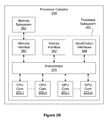
FIG. 3B illustrates a processor complex 310 within the digital photographic system 300 of FIG. 3A, in accordance with one embodiment. As an option, the processor complex 310 may be implemented in the context of the details of any of the Figures disclosed herein. Of course, however, the processor complex 310 may be implemented in any desired environment. Further, the aforementioned definitions may equally apply to the description below.
As shown, the processor complex 310 includes a processor subsystem 360 and may include a memory subsystem 362. In one embodiment, processor complex 310 may comprise a system on a chip (SoC) device that implements processor subsystem 360, and memory subsystem 362 comprises one or more DRAM devices coupled to the processor subsystem 360. In another embodiment, the processor complex 310 may comprise a multi-chip module (MCM) encapsulating the SoC device and the one or more DRAM devices comprising the memory subsystem 362.
The processor subsystem 360 may include, without limitation, one or more central processing unit (CPU) cores 370, a memory interface 380, input/output interfaces unit 384, and a display interface unit 382, each coupled to an interconnect 374. The one or more CPU cores 370 may be configured to execute instructions residing within the memory subsystem 362, volatile memory 318, NV memory 316, or any combination thereof. Each of the one or more CPU cores 370 may be configured to retrieve and store data through interconnect 374 and the memory interface 380. In one embodiment, each of the one or more CPU cores 370 may include a data cache, and an instruction cache. Additionally, two or more of the CPU cores 370 may share a data cache, an instruction cache, or any combination thereof. In one embodiment, a cache hierarchy is implemented to provide each CPU core 370 with a private cache layer, and a shared cache layer.
In some embodiments, processor subsystem 360 may include one or more graphics processing unit (GPU) cores 372. Each GPU core 372 may comprise a plurality of multi-threaded execution units that may be programmed to implement, without limitation, graphics acceleration functions. In various embodiments, the GPU cores 372 may be configured to execute multiple thread programs according to well-known standards (e.g. OpenGL™, WebGL™, OpenCL™, CUDA™, etc.), and/or any other programmable rendering graphic standard. In certain embodiments, at least one GPU core 372 implements at least a portion of a motion estimation function, such as a well-known Harris detector or a well-known Hessian-Laplace detector. Such a motion estimation function may be used at least in part to align images or portions of images within an image stack. For example, in one embodiment, an HDR image may be compiled based on an image stack, where two or more images are first aligned prior to compiling the HDR image.
As shown, the interconnect 374 is configured to transmit data between and among the memory interface 380, the display interface unit 382, the input/output interfaces unit 384, the CPU cores 370, and the GPU cores 372. In various embodiments, the interconnect 374 may implement one or more buses, one or more rings, a cross-bar, a mesh, or any other technically feasible data transmission structure or technique. The memory interface 380 is configured to couple the memory subsystem 362 to the interconnect 374. The memory interface 380 may also couple NV memory 316, volatile memory 318, or any combination thereof to the interconnect 374. The display interface unit 382 may be configured to couple a display unit 312 to the interconnect 374. The display interface unit 382 may implement certain frame buffer functions (e.g. frame refresh, etc.). Alternatively, in another embodiment, the display unit 312 may implement certain frame buffer functions (e.g. frame refresh, etc.). The input/output interfaces unit 384 may be configured to couple various input/output devices to the interconnect 374.
In certain embodiments, a camera module 330 is configured to store exposure parameters for sampling each image associated with an image stack. For example, in one embodiment, when directed to sample a photographic scene, the camera module 330 may sample a set of images comprising the image stack according to stored exposure parameters. A software module comprising programming instructions executing within a processor complex 310 may generate and store the exposure parameters prior to directing the camera module 330 to sample the image stack. In other embodiments, the camera module 330 may be used to meter an image or an image stack, and the software module comprising programming instructions executing within a processor complex 310 may generate and store metering parameters prior to directing the camera module 330 to capture the image. Of course, the camera module 330 may be used in any manner in combination with the processor complex 310.
In one embodiment, exposure parameters associated with images comprising the image stack may be stored within an exposure parameter data structure that includes exposure parameters tier one or more images. In another embodiment, a camera interface unit (not shown in FIG. 3B) within the processor complex 310 may be configured to read exposure parameters from the exposure parameter data structure and to transmit associated exposure parameters to the camera module 330 in preparation of sampling a photographic scene. After the camera module 330 is configured according to the exposure parameters, the camera interface may direct the camera module 330 to sample the photographic scene; the camera module 330 may then generate a corresponding image stack. The exposure parameter data structure may be stored within the camera interface unit, a memory circuit within the processor complex 310, volatile memory 318, NV memory 316, the camera module 330, or within any other technically feasible memory circuit. Further, in another embodiment, a software module executing within processor complex 310 may generate and store the exposure parameter data structure.
FIG. 3C illustrates a digital camera 302, in accordance with one embodiment. As an option, the digital camera 302 may be implemented in the context of the details of any of the Figures disclosed herein. Of course, however, the digital camera 302 may be implemented in any desired environment. Further, the aforementioned definitions may equally apply to the description below.
In one embodiment, the digital camera 302 may be configured to include a digital photographic system, such as digital photographic system 300 of FIG. 3A. As shown, the digital camera 302 includes a camera module 330, which may include optical elements configured to focus optical scene information representing a photographic scene onto an image sensor, which may be configured to convert the optical scene information to an electronic representation of the photographic scene.
Additionally, the digital camera 302 may include a strobe unit 336, and may include a shutter release button 315 for triggering a photographic sample event, whereby digital camera 302 samples one or more images comprising the electronic representation. In other embodiments, any other technically feasible shutter release mechanism may trigger the photographic sample event (e.g. such as a timer trigger or remote control trigger, etc).
FIG. 3D illustrates a wireless mobile device 376, in accordance with one embodiment. As an option, the mobile device 376 may be implemented in the context of the details of any of the Figures disclosed herein. Of course, however, the mobile device 376 may be implemented in any desired environment. Further, the aforementioned definitions may equally apply to the description below.
In one embodiment, the mobile device 376 may be configured to include a digital photographic system (e.g. such as digital photographic system 300 of FIG. 3A), which is configured to sample a photographic scene. In various embodiments, a camera module 330 may include optical elements configured to focus optical scene information representing the photographic scene onto an image sensor, which may be configured to convert the optical scene information to an electronic representation of the photographic scene. Further, a shutter release command may be generated through any technically feasible mechanism, such as a virtual button, which may be activated by a touch gesture on a touch entry display system comprising display unit 312, or a physical button, which may be located on any face or surface of the mobile device 376. Of course, in other embodiments, any number of other buttons, external inputs/outputs, or digital inputs/outputs may be included on the mobile device 376, and which may be used in conjunction with the camera module 330.
As shown, in one embodiment, a touch entry display system comprising display unit 312 is disposed on the opposite side of mobile device 376 from camera module 330. In certain embodiments, the mobile device 376 includes a user-facing camera module 331 and may include a user-facing strobe unit (not shown). Of course, in other embodiments, the mobile device 376 may include any number of user-facing camera modules or rear-facing camera modules, as well as any number of user-facing strobe units or rear-facing strobe units.
In some embodiments, the digital camera 302 and the mobile device 376 may each generate and store a synthetic image based on an image stack sampled by camera module 330. The image stack may include one or more images sampled under ambient lighting conditions, one or more images sampled under strobe illumination from strobe unit 336, or a combination thereof.
FIG. 3E illustrates camera module 330, in accordance with one embodiment. As an option, the camera module 330 may be implemented in the context of the details of any of the Figures disclosed herein. Of course, however, the camera module 330 may be implemented in any desired environment. Further, the aforementioned definitions may equally apply to the description below.
In one embodiment, the camera module 330 may be configured to control strobe unit 336 through strobe control signal 338. As shown, a lens 390 is configured to focus optical scene information 352 onto image sensor 332 to be sampled. In one embodiment, image sensor 332 advantageously controls detailed timing of the strobe unit 336 though the strobe control signal 338 to reduce inter-sample time between an image sampled with the strobe unit 336 enabled, and an image sampled with the strobe unit 336 disabled. For example, the image sensor 332 may enable the strobe unit 336 to emit strobe illumination 350 less than one microsecond for any desired length) after image sensor 332 completes an exposure time associated with sampling an ambient image and prior to sampling a strobe image.
In other embodiments, the strobe illumination 350 may be configured based on a desired one or more target points. For example, in one embodiment, the strobe illumination 350 may light up an object in the foreground, and depending on the length of exposure time, may also light up an object in the background of the image. In one embodiment, once the strobe unit 336 is enabled, the image sensor 332 may then immediately begin exposing a strobe image. The image sensor 332 may thus be able to directly control sampling operations, including enabling and disabling the strobe unit 336 associated with generating an image stack, which may comprise at least one image sampled with the strobe unit 336 disabled, and at least one image sampled with the strobe unit 336 either enabled or disabled. In one embodiment, data comprising the image stack sampled by the image sensor 332 is transmitted via interconnect 334 to a camera interface unit 386 within processor complex 310. In some embodiments, the camera module 330 may include an image sensor controller, which may be configured to generate the strobe control signal 338 in conjunction with controlling operation of the image sensor 332.
FIG. 3F illustrates a camera module 330, in accordance with one embodiment. As an option, the camera module 330 may be implemented in the context of the details of any of the Figures disclosed herein. Of course, however, the camera module 330 may be implemented in any desired environment. Further, the aforementioned definitions may equally apply to the description below.
In one embodiment, the camera module 330 may be configured to sample an image based on state information for strobe unit 336. The state information may include, without limitation, one or more strobe parameters (e.g. strobe intensity, strobe color, strobe time, etc.), for directing the strobe unit 336 to generate a specified intensity and/or color of the strobe illumination 350. In one embodiment, commands for configuring the state information associated with the strobe unit 336 may be transmitted through a strobe control signal 338, which may be monitored by the camera module 330 to detect when the strobe unit 336 is enabled. For example, in one embodiment, the camera module 330 may detect when the strobe unit 336 is enabled or disabled within a microsecond or less of the strobe unit 336 being enabled or disabled by the strobe control signal 338. To sample an image requiring strobe illumination, a camera interface unit 386 may enable the strobe unit 336 by sending an enable command through the strobe control signal 338. In one embodiment, the camera interface unit 386 may be included as an interface of input/output interfaces 384 in a processor subsystem 360 of the processor complex 310 of FIG. 3B. The enable command may comprise a signal level transition, a data packet, a register write, or any other technically feasible transmission of a command. The camera module 330 may sense that the strobe unit 336 is enabled and then cause image sensor 332 to sample one or more images requiring strobe illumination while the strobe unit 336 is enabled. In such an implementation, the image sensor 332 may be configured to wait for an enable signal destined for the strobe unit 336 as a trigger signal to begin sampling a new exposure.
In one embodiment, camera interface unit 386 may transmit exposure parameters and commands to camera module 330 through interconnect 334. In certain embodiments, the camera interface unit 386 may be configured to directly control strobe unit 336 by transmitting control commands to the strobe unit 336 through strobe control signal 338. By directly controlling both the camera module 330 and the strobe unit 336, the camera interface unit 386 may cause the camera module 330 and the strobe unit 336 to perform their respective operations in precise time synchronization. In one embodiment, precise time synchronization may be less than five hundred microseconds of event timing error. Additionally, event timing error may be a difference in time from an intended event occurrence to the time of a corresponding actual event occurrence.
In another embodiment, camera interface unit 386 may be configured to accumulate statistics while receiving image data from camera module 330. In particular, the camera interface unit 386 may accumulate exposure statistics for a given image while receiving image data for the image through interconnect 334. Exposure statistics may include, without limitation, one or more of an intensity histogram, a count of over-exposed pixels, a count of under-exposed pixels, an intensity-weighted sum of pixel intensity, or any combination thereof. The camera interface unit 386 may present the exposure statistics as memory-mapped storage locations within a physical or virtual address space defined by a processor, such as one or more of CPU cores 370, within processor complex 310. In one embodiment, exposure statistics reside in storage circuits that are mapped into a memory-mapped register space, which may be accessed through the interconnect 334. In other embodiments, the exposure statistics are transmitted in conjunction with transmitting pixel data for a captured image. For example, the exposure statistics for a given image may be transmitted as in-line data, following transmission of pixel intensity data for the captured image. Exposure statistics may be calculated, stored, or cached within the camera interface unit 386.
In one embodiment, camera interface unit 386 may accumulate color statistics for estimating scene white balance. Any technically feasible color statistics may be accumulated for estimating white balance, such as a sum of intensities for different color channels comprising red, green, and blue color channels. The sum of color channel intensities may then be used to perform a white balance color correction on an associated image, according to a white balance model such as a gray-world white balance model. In other embodiments, curve-fitting statistics are accumulated for a linear or a quadratic curve fit used for implementing white balance correction on an image.
In one embodiment, camera interface unit 386 may accumulate spatial color statistics for performing color-matching between or among images, such as between or among an ambient image and one or more images sampled with strobe illumination. As with the exposure statistics, the color statistics may be presented as memory-mapped storage locations within processor complex 310. In one embodiment, the color statistics are mapped in a memory-mapped register space, which may be accessed through interconnect 334, within processor subsystem 360. In other embodiments, the color statistics may be transmitted in conjunction with transmitting pixel data for a captured image. For example, in one embodiment, the color statistics for a given image may be transmitted as in-line data, following transmission of pixel intensity data for the image. Color statistics may be calculated, stored, or cached within the camera interface 386.
In one embodiment, camera module 330 may transmit strobe control signal 338 to strobe unit 336, enabling the strobe unit 336 to generate illumination while the camera module 330 is sampling an image. In another embodiment, camera module 330 may sample an image illuminated by strobe unit 336 upon receiving an indication signal from camera interface unit 386 that the strobe unit 336 is enabled. In yet another embodiment, camera module 330 may sample an image illuminated by strobe unit 336 upon detecting strobe illumination within a photographic scene via a rapid rise in scene illumination. In one embodiment, a rapid rise in scene illumination may include at least a rate of increasing intensity consistent with that of enabling strobe unit 336. In still yet another embodiment, camera module 330 may enable strobe unit 336 to generate strobe illumination while sampling one image, and disable the strobe unit 336 while sampling a different image.
FIG. 3G illustrates camera module 330, in accordance with one embodiment. As an option, the camera module 330 may be implemented in the context of the details of any of the Figures disclosed herein. Of course, however, the camera module 330 may be implemented in any desired environment. Further, the aforementioned definitions may equally apply to the description below.
In one embodiment, the camera module 330 may be in communication with an application processor 335. The camera module 330 is shown to include image sensor 332 in communication with a controller 333. Further, the controller 333 is shown to be in communication with the application processor 335.
In one embodiment, the application processor 335 may reside outside of the camera module 330. As shown, the lens 390 may be configured to focus optical scene information onto image sensor 332 to be sampled. The optical scene information sampled by the image sensor 332 may then be communicated from the image sensor 332 to the controller 333 for at least one of subsequent processing and communication to the application processor 335. In another embodiment, the controller 333 may control storage of the optical scene information sampled by the image sensor 332, or storage of processed optical scene information.
In another embodiment, the controller 333 may enable a strobe unit to emit strobe illumination for a short time duration (e.g. less than one microsecond, etc.) after image sensor 332 completes an exposure time associated with sampling an ambient image. Further, the controller 333 may be configured to generate strobe control signal 338 in conjunction with controlling operation of the image sensor 332.
In one embodiment, the image sensor 332 may be a complementary metal oxide semiconductor (CMOS) sensor or a charge-coupled device (CCD) sensor. In another embodiment, the controller 333 and the image sensor 332 may be packaged together as an integrated system or integrated circuit. In yet another embodiment, the controller 333 and the image sensor 332 may comprise discrete packages. In one embodiment, the controller 333 may provide circuitry for receiving optical scene information from the image sensor 332, processing of the optical scene information, timing of various functionalities, and signaling associated with the application processor 335. Further, in another embodiment, the controller 333 may provide circuitry for control of one or more of exposure, shattering, white balance, and gain adjustment. Processing of the optical scene information by the circuitry of the controller 333 may include one or more of gain application, amplification, and analog-to-digital conversion. After processing the optical scene information, the controller 333 may transmit corresponding digital pixel data, such as to the application processor 335.
In one embodiment, the application processor 335 may be implemented on processor complex 310 and at least one of volatile memory 318 and NV memory 316, or any other memory device and/or system. The application processor 335 may be previously configured fir processing of received optical scene information or digital pixel data communicated from the camera module 330 to the application processor 335.
FIG. 4 illustrates a network service system 400, in accordance with one embodiment. As an option, the network service system 400 may be implemented in the context of the details of any of the Figures disclosed herein. Of course, however, the network service system 400 may be implemented in any desired environment. Further, the aforementioned definitions may equally apply to the description below.
In one embodiment, the network service system 400 may be configured to provide network access to a device implementing a digital photographic system. As shown, network service system 400 includes a wireless mobile device 376, a wireless access point 472, a data network 474, data center 480, and a data center 481. The wireless mobile device 376 may communicate with the wireless access point 472 via a digital radio link 471 to send and receive digital data, including data associated with digital images. The wireless mobile device 376 and the wireless access point 472 may implement any technically feasible transmission techniques for transmitting digital data via digital a radio link 471 without departing the scope and spirit of the present invention. In certain embodiments, one or more of data centers 480, 481 may be implemented using virtual constructs so that each system and subsystem within a given data center 480, 481 may comprise virtual machines configured to perform specified data processing and network tasks. In other implementations, one or more of data centers 480, 481 may be physically distributed over a plurality of physical sites.
The wireless mobile device 376 may comprise a smart phone configured to include a digital camera, a digital camera configured to include wireless network connectivity, a reality augmentation device, a laptop configured to include a digital camera and wireless network connectivity, or any other technically feasible computing device configured to include a digital photographic system and wireless network connectivity.
In various embodiments, the wireless access point 472 may be configured to communicate with wireless mobile device 376 via the digital radio link 471 and to communicate with the data network 474 via any technically feasible transmission media, such as any electrical, optical, or radio transmission media. For example, in one embodiment, wireless access point 472 may communicate with data network 474 through an optical fiber coupled to the wireless access point 472 and to a router system or a switch system within the data network 474. A network link 475, such as a wide area network (WAN) link, may be configured to transmit data between the data network 474 and the data center 480.
In one embodiment, the data network 474 may include routers, switches, tong-haul transmission systems, provisioning systems, authorization systems, and any technically feasible combination of communications and operations subsystems configured to convey data between network endpoints, such as between the wireless access point 472 and the data center 480. In one implementation, a wireless the mobile device 376 may comprise one of a plurality of wireless mobile devices configured to communicate with the data center 480 via one or more wireless access points coupled to the data network 474.
Additionally, in various embodiments, the data center 480 may include, without limitation, a switch/router 482 and at least one data service system 484. The switch/router 482 may be configured to forward data traffic between and among a network link 475, and each data service system 484. The switch/router 482 may implement any technically feasible transmission techniques, such as Ethernet media layer transmission, layer 2 switching, layer 3 routing, and the like. The switch/router 482 may comprise one or more individual systems configured to transmit data between the data service systems 484 and the data network 474.
In one embodiment, the switch/router 482 may implement session-level load balancing among a plurality of data service systems 484. Each data service system 484 may include at least one computation system 488 and may also include one or more storage systems 486. Each computation system 488 may comprise one or more processing units, such as a central processing unit, a graphics processing unit, or any combination thereof. A given data service system 484 may be implemented as a physical system comprising one or more physically distinct systems configured to operate together. Alternatively, a given data service system 484 may be implemented as a virtual system comprising one or more virtual systems executing on an arbitrary physical system. In certain scenarios, the data network 474 may be configured to transmit data between the data center 480 and another data center 481, such as through a network link 476.
In another embodiment, the network service system 400 may include any networked mobile devices configured to implement one or more embodiments of the present invention. For example, in some embodiments, a peer-to-peer network, such as an ad-hoc wireless network, may be established between two different wireless mobile devices. In such embodiments, digital image data may be transmitted between the two wireless mobile devices without having to send the digital image data to a data center 480.
FIG. 5 shows a method 500 for determining if a network is available, in accordance with one embodiment. As an option, the method 500 may be implemented in the context of the details of any of the Figures. Of course, however, the method 500 may be carried out in any desired environment. Further, the aforementioned definitions may equally apply to the description below.
As shown, an image operation is requested. See operation 502. Next, it is determined if a network is available. See decision 504. If it is determined a network is not available, a local version of image operations is performed. See operation 506. Next, the local image is stored. See operation 508. It is then determined if a network is available. See decision 510. If it is determined that a network is not available, then the flow loops back to decision 510.
If it is determined that a network is available (either by decision 504 or 510), then a server version of image operations is performed. See operation 512. Next, the image is updated. See operation 514.
In one embodiment, the local version of image operations 506 may be performed regardless of whether the network is available. For example, in one embodiment, the client device may utilize a hardwired component to correct the white balance (or any desired parameter, etc.). In other embodiments, before a local version of image operations 506 is performed, it may be determined whether a network is available, and if it is, then local version of image operations 506 may not be performed.
In another embodiment, determining whether a network is available may include determining whether a network resource (e.g. a server, etc.) is available. In other embodiments, determining whether a network is available may include determining whether a preferred network is within range (e.g. local WiFi network, Bluetooth network, etc.). In certain embodiments, determining whether a network is available may include attempting to contact a wireless access point, such as a WiFi access point or a cellular access point. Contact with the less access point may be initially established through any technically feasible discovery protocol.
In some embodiments, a network may be available but a network resource (e.g. server, etc.) may not be available. In such an embodiment, a local version of image operations (operation 506) may be performed, and local image may be stored (operation 508) until the network resource is available. In certain embodiments, determining whether a network resource is available may include attempting to contact the network resource, such as through a well-known URL or a well-known interact protocol (IP) address. Any technically feasible authentication and/or authorization mechanism may be implemented to permit access to the network resource by a client device.
In one embodiment, updating an image, operation 514, may include, but not be limited to, sending the server-processed one or more images back to a client, saving the one or more images to storage (local storage or networked storage, e.g. an online database system, Dropbox™ service, Onedrive™ service, etc.), embedding metadata relating to information identified (e.g. products, brand, location, etc.) in the one or more images, sending the one or more images to a specific location (e.g. destination address, etc.), and/or taking any other action relating to the server-processed one or more images.
FIG. 6 shows a method 600 for determining if a network threshold is exceeded, in accordance with one embodiment. As an option, the method 600 may be implemented in the context of the details of any of the Figures. Of course, however, the method 600 may be carried out in any desired environment. Further, the aforementioned definitions may equally apply to the description below.
As shown, an image operation is requested. See operation 602. Next, it is determined if a network threshold (e.g. an available transmission data rate) is exceeded. See decision 604. If it is determined a network threshold is not exceeded, a local version of image operations is performed. See operation 606. After, the local image is stored. See operation 608. It is then determined if a network threshold is exceeded. See decision 610. If it is determined that a network threshold is not exceeded, then the flow loops back to decision 610.
If it is determined that a network threshold is exceeded (either by decision 604 or 610), then a server version of image operations is performed. See operation 612. Next, the image is updated. See operation 614.
In one embodiment, a network threshold may be a minimum upload rate, minimum download rate, percentage of timeout for calls, percentage of erroneous outbound packets, percentage of erroneous inbound packets, a network type (e.g. wifi, etc.) and/or any other network metric. In another embodiment, more than one threshold may exist with a network threshold. For example, in one embodiment, a first threshold may require a minimum of 1 megabit per second upload rate for images (or videos) in excess of 100 megabytes, and a second threshold may require a WiFi connection for images (or videos) in excess of 500 megabytes. Of course, in other embodiments, the thresholds may be altered and/or configured in any manner.
In one embodiment, the local version of image operations 606 may be performed regardless of whether the network threshold is exceeded. For example, in one embodiment, the client device may utilize a hardwired component to correct the white balance (or any desired parameter, etc.). In other embodiments, before a local version of image operations 606 is performed, it may be determined whether a network threshold is exceeded, and if it is, then local version of image operations 606 may not be performed.
In some embodiments, a network threshold may be met but a network resource (e.g. server, etc.) may not be available. In such an embodiment, a local version of image operations (operation 606) may be performed, and local image may be stored (operation 608) until the network resource is available.
In one embodiment, updating an image, operation 614, may include, but not be limited to, sending the server-processed one or more images back to a client, saving the one or more images to storage (local storage or networked storage, e.g. an online database system, Dropbox™ service, Onedrive™ service, etc.), embedding metadata relating to information identified (e.g. products, brand, location, etc.) in the one or more images, sending the one or more images to a specific location (e.g. destination address, etc.), and/or taking any other action relating to the server-processed one or more images.
FIG. 7 shows a method 700 for determining if a server is available, in accordance with one embodiment. As an option, the method 700 may be implemented in the context of the details of any of the Figures. Of course, however, the method 700 may be carried out in any desired environment. Further, the aforementioned definitions may equally apply to the description below.
As shown, an image operation is requested. See operation 702. Next, it is determined if a server is available. See decision 704. If it is determined a server is not available, a basic HDR is applied. See operation 706. After, the image is stored. See operation 708. It is then determined if a server is available. See decision 710. If it is determined that a server is not available, then the flow loops back to decision 710.
If it is determined that a server is available (either by decision 704 or 710), then a server may apply rich optimization (operation 712), a blur optimization (operation 714), and/or recognition (operation 716), or any combination thereof.
In various embodiments, if a server is not available, a client device may perform one or more image operations, including but not limited to basic HDR, de-hazing, contrast enhancement, and/or white balance correction. In other embodiments, a server may perform, at a minimum, the same one or more image operations as the client device, and may also further provide rich optimization processing, including, but not limited to, blurring, de-convolve/de-convolution operations, layer blending, multi-point corrections (e.g. based on white balance, based on exposure points, etc.), etc.
In one embodiment, once a server is available, processing by the server may include at least some recognition and/or identification of non-facial items. For example, products, items, brands, locations, monuments, and/or any other items may be recognized and identified. As an example, in one embodiment, an image may be captured of a man standing in front of the White House. In such an embodiment, once a network resource is available, processing by the network resource may include identifying the building as the “White House,” identifying his shirt as being sold by Abercrombie & Fitch™ (or any other distinguishable article of clothing, etc.), identifying the location based on the surroundings (e.g. northwest corner of the lot next to the White House, etc.), and/or identifying any other item captured in the photo. Other embodiments relating to the recognition and/or identification of non-facial items may be applicable as disclosed herein.
FIG. 8 shows a user interface 800 for requesting one or more image operations on a local device, in accordance with one embodiment. As an option, the user interface 800 may be implemented in the context of the details of any of the Figures. Of course, however, the user interface 800 may be carried out in any desired environment. Further, the aforementioned definitions may equally apply to the description below.
As shown, the user interface 800 may include an image 802, a first indication point 804, a slider track 806, a second indication point 808, a slider control 810, an image selection 812, and a filter 814. In various embodiments, the user interface 800 may be implemented for a local device, for a mobile device, and/or for any other device apart from the server.
In one embodiment, the slider track 806 may be dependent on the selected filter 814. For example, in one embodiment, the filter may include a HDR effect, the slider being configured to alter the HDR effect between “less HDR” (e.g. first indication point 804, etc) and “more HDR” (e.g. second indication point 808, etc.), the configuration occurring through input on a slider control 810. In other embodiments, the filter 814 comprises a filter selection tool, which may enable the user to select one or more filters to be individually or collectively applied to generate the image 802. In certain embodiments, the filter selection tool provides a set of locally available filters, a set of server-based filters, or a combination thereof.
In one embodiment, the image 802 being displayed may include one or more images. For example, in one embodiment, the filter being applied may relate to a basic HDR feature which may blend two or more images. In one embodiment, image selection 812 may be used to select which images are used for the filter. In other embodiments, image selection may ha carried out using a thumbnail selector, a swipe gesture, or any other technically feasible image selection techniques.
In another embodiment, the filters 814 displayed may be dependent on the type of network connection, one or more network thresholds, availability of a network resource, availability of a server, and/or any other requirement. For example, in one embodiment, if a network resource (e.g. server, etc.) is not available, then more filters may be displayed on user interface 800. In another embodiment, if a network resource (e.g. server, etc.) is available, then fewer filters may be displayed on user interface 800. For example, in one embodiment, if a network resource is available, then the user may only have the ability to perform a basic HDR. In another embodiment, if a network resource (e.g. server, etc.) is not available, then the user may have the ability to perform a basic HDR, modify the exposure, modify the saturation, modify the color scheme, and/or potentially change any other parameter associated with the image.
FIG. 9 shows a user interface 900 for requesting one or more image operations on a server device, in accordance with one embodiment. As an option, the user interface 900 may be implemented in the context of the details of any of the Figures. Of course, however, the user interface 900 may be carried out in any desired environment. Further, the aforementioned definitions may equally apply to the description below.
As shown, the user interface 900 may include an image 902, a first indication point 904, a slider track 906, a second indication point 908, a slider control 910, an image selection 912, and a filter 914. In various embodiments, the user interface 900 may be implemented in association with a server device. For example, in one embodiment, the user interface 900 may be used to control, at least in part, one aspect associated with the server device.
In one embodiment, the slider track 906 may be dependent on the selected filter 914. For example, in one embodiment, the filter may include a HDR effect, the slider being configured to alter the HDR effect between “less HDR” (e.g. first indication point 804, etc.) and “more HDR” (e.g. second indication point 808, etc.), the configuration occurring through input on a slider control 810.
In one embodiment, the image 902 being displayed may include one or more images. For example, in one embodiment, the filter being applied may relate to a HDR feature which may blend two or more images. In one embodiment, image selection 912 may be used to select which images are used for the filter.
In various embodiments, the filter 914 may include, but not be limited to, a HDR effect, a blur effect, and/or recognize or identify objects within image 902. In one embodiment, a HDR effect may include the ability to control a haze, contrast, and/or any other parameter, as well as the ability to select to optimize the image. In another embodiment, a blur effect may include the ability to control the de-convolution of the image. Additionally, in one embodiment, recognizing or identifying objects may include the ability to identify and/or recognize non-facial items. For example, products, items, brands, locations, monuments, and/or any other items may be recognized and identified, consistent with the disclosure herein. Furthermore, such recognition/identification may be deferred based on network availability, and may additionally be performed in conjunction with identifying sources from which to purchase one or more identified items within image 902.
FIG. 10 illustrates a user interface (UI) system 1000 for generating a combined image 1020, according to one embodiment. As an option, the UI system 1000 may be implemented in the context of the details of any of the Figures disclosed herein. Of course, however, the UI system 1000 may be carried out in any desired environment. Further, the aforementioned definitions may equally apply to the description below.
In one embodiment, a combined image 1020 comprises a combination of at least two related digital images. In one embodiment, the combined image 1020 comprises, without limitation, a combined rendering of a first digital image and a second digital image, such first digital image 732 and second digital image 734 of FIG. 7. In another embodiment, the digital images used to compute the combined image 1020 may be generated by amplifying an analog signal with at least two different gains, where the analog signal includes optical scene information captured based on an optical image focused on an image sensor. In yet another embodiment, the analog signal may be amplified using the at least two different gains on a pixel-by-pixel or frame-by-frame basis.
In one embodiment, the UI system 1000 presents a display image 1010 that includes, without limitation, a combined image 1020, a slider control 1030 configured to move along track 1032, and two or more indication points 1040, which may each include a visual marker displayed within display image 1010.
In one embodiment, the UI system 1000 is generated by an adjustment tool executing within a processor complex 310 of a digital photographic system 300, and the display image 1010 is displayed on display unit 312. In one embodiment, at least two digital images, such as the at least two related digital images, comprise source images for generating the combined image 1020. The at least two digital images may reside within NV memory 316, volatile memory 318, memory subsystem 362 or any combination thereof. In another embodiment, the UI system 1000 is generated by an adjustment tool executing within a computer system, such as a laptop computer or a desktop computer. The at least two digital images may be transmitted to the computer system or may be generated by an attached camera device. In yet another embodiment, the UI system 1000 may be generated by a cloud-based server computer system, which may download the at least two digital images to a client browser, which may execute combining operations described below. In another embodiment, the UI system 1000 is generated by a cloud-based server computer system, which receives the at least two digital images from a digital photographic system in a mobile device, and which may execute the combining operations described below in conjunction with generating combined image 1020.
The slider control 1030 may be configured to move between two end points corresponding to indication points 1040-A and 1040-C. One or more indication points, such as indication point 1040-B may be positioned between the two end points. Each indication point 1040 may be associated with a specific version of combined image 1020, or a specific combination of the at least two digital images. For example, the indication point 1040-A may be associated with a first digital image generated utilizing a first gain, and the indication point 1040-C may be associated with a second digital image generated utilizing a second gain, where both of the first digital image and the second digital image are generated from a same analog signal of a single captured photographic scene. In one embodiment, when the slider control 1030 is positioned directly over the indication point 1040-A, only the first digital image may be displayed as the combined image 1020 in the display image 1010, and similarly when the slider control 1030 is positioned directly over the indication point 1040-C, only the second digital image may be displayed as the combined image 1020 in the display image 1010.
In one embodiment, indication point 1040-B may be associated with a blending of the first digital image and the second digital image. For example, when the slider control 1030 is positioned at the indication point 1040-B, the combined image 1020 may be a blend of the first digital image and the second digital image. In one embodiment, blending of the first digital image and the second digital image may comprise alpha blending, brightness blending, dynamic range blending, and/or tone mapping or other non-linear blending and mapping operations. In another embodiment, any blending of the first digital image and the second digital image may provide a new image that has a greater dynamic range or other visual characteristics that are different than either of the first image and the second image alone. Thus, a blending of the first digital image and the second digital image may provide a new computed HDR image that may be displayed as combined image 1020 or used to generate combined image 1020. To this end, a first digital signal and a second digital signal may be combined, resulting in at least a portion of a HDR image. Further, one of the first digital signal and the second digital signal may be further combined with at least a portion of another digital image or digital signal. In one embodiment, the other digital image may include another HDR image.
In one embodiment, when the slider control 1030 is positioned at the indication point 1040-A, the first digital image is displayed as the combined image 1020, and when the slider control 1030 is positioned at the indication point 1040-C, the second digital image is displayed as the combined image 1020; furthermore, when slider control 1030 is positioned at indication point 1040-B, a blended image is displayed as the combined image 1020. In such an embodiment, when the slider control 1030 is positioned between the indication point 1040-A and the indication point 1040-C, a mix (e.g. blend) weight may be calculated for the first digital image and the second digital image. For the first digital image, the mix weight may be calculated as having a value of 0.0 when the slider control 1030 is at indication point 1040-C and a value of 1.0 when slider control 1030 is at indication point 1040-A, with a range of mix weight values between 0.0 and 1.0 located between the indication points 1040-C and 1040-A, respectively. Referencing the mix operation instead to the second digital image, the mix weight may be calculated as having a value of 0.0 when the slider control 1030 is at indication point 1040-A and a value of 1.0 when slider control 1030 is at indication point 1040-C, with a range of mix weight values between 0.0 and 1.0 located between the indication points 1040-A and 1040-C, respectively.
A mix operation may be applied to the first digital image and the second digital image based upon at least one mix weight value associated with at least one of the first digital image and the second digital image. In one embodiment, a mix weight of 1.0 gives complete mix weight to the digital image associated with the 1.0 mix weight. In this way, a user may blend between the first digital image and the second digital image. To this end, a first digital signal and a second digital signal may be blended in response to user input. For example, sliding indicia may be displayed, and a first digital signal and a second digital signal may be blended in response to the sliding indicia being manipulated by a user.
This system of mix weights and mix operations provides a UI tool for viewing the first digital image, the second digital image, and a blended image as a gradual progression from the first digital image to the second digital image. In one embodiment, a user may save a combined image 1020 corresponding to an arbitrary position of the slider control 1030. The adjustment tool implementing the UI system 1000 may receive a command to save the combined image 1020 via any technically feasible gesture or technique. For example, the adjustment tool may be configured to save the combined image 1020 when a user gestures within the area occupied by combined image 1020. Alternatively, the adjustment tool may save the combined image 1020 when a user presses, but does not otherwise move the slider control 1030. In another implementation, the adjustment tool may save the combined image 1020 when a user gestures, such as by pressing a UI element (not shown), such as a save button, dedicated to receive a save command.
To this end, a slider control may be used to determine a contribution of two or more digital images to generate a final computed image, such as combined image 1020. Persons skilled in the art will recognize that the above system of mix weights and mix operations may be generalized to include two or more indication points, associated with two or more related images. Such related images may comprise, without limitation, any number of digital images that have been generated using a same analog signal to have different brightness values, which may have zero interframe time.
Furthermore, a different continuous position UI control, such as a rotating knob, may be implemented rather than the slider 1030 to provide mix weight input or color adjustment input from the user.
FIG. 11 shows a method 1100 for generating a combined image, according to one embodiment. As an option, the method 1100 may be implemented in the context of the details of any of the Figures disclosed herein. Of course, however, the method 1100 may be carried out in any desired environment. Further, the aforementioned definitions may equally apply to the description below.
The method 1100 begins in step 1110, where an adjustment tool executing within a processor complex, such as processor complex 310, loads at least two related source images, such as the first digital image and the second digital image described in the context of FIG. 10. In step 1112, the adjustment tool initializes a position for a UI control, such as slider control 1030 of FIG. 10, to a default setting. In one embodiment, the default setting comprises an end point, such as indication point 1040-A, for a range of values for the UI control. In another embodiment, the default setting comprises a calculated value based on one or more of the at least two related source images. In certain embodiments, the default setting is initialized to a value previously selected by a user in association with an image object comprising at least the first digital image and the second digital image.
In step 1114, the adjustment tool generates and displays a combined image, such as combined image 1020 of FIG. 10, based on a position of the UI control and the at least two related source images. In one embodiment, generating the combined image comprises mixing the at least two related source images as described previously in FIG. 10. In step 1116, the adjustment tool receives user input. The user input may include, without limitation, a UI gesture such as a selection gesture or click gesture within display image 1010. If, in step 1120, the user input should change the position of the UI control, then the adjustment tool changes the position of the UI control and the method proceeds back to step 1114. Otherwise, the method proceeds to step 1130.
If, in step 1130, the user input does not comprise a command to exit, then the method proceeds to step 1140, where the adjustment tool performs a command associated with the user input. In one embodiment, the command comprises a save command and the adjustment tool then saves the combined image, which is generated according to a position of the UI control. The method then proceeds back to step 1116.
Returning to step 1130, if the user input comprises a command to exit, then the method terminates in step 1190, where the adjustment tool exits, thereby terminating execution.
In summary, a technique is disclosed for generating a new digital photograph that beneficially blends a first digital image and a second digital image, where the first digital image and the second digital image are both based on a single analog signal received from an image sensor. The first digital image may be blended with the second digital image based on a function that implements any technically feasible blend technique. An adjustment tool may implement a user interface technique that enables a user to select and save the new digital photograph from a gradation of parameters for combining related images.
One advantage of the present invention is that a digital photograph may be selectively generated based on user input using two or more different exposures of a single capture of a photographic scene. Accordingly, the digital photograph generated based on the user input may have a greater dynamic range than any of the individual exposures. Further, the generation of an HDR image may be performed at varying degrees of quality and visual effect based on availability of a network resource for performing computationally intensive image processing. Furthermore, non-facial object identification may be performed against a database of object identification data that may not readily be stored or timely updated on a mobile device. The disclosed technique advantageously provides server-based identification database scale in settings where network access is not available and where such a database is not suitable for local storage on a mobile device.
Still yet, in various embodiments, one or more of the techniques disclosed herein may be applied to a variety of markets and/or products. For example, although the techniques have been disclosed in reference to a photo capture, they may be applied to televisions, web conferencing (or live streaming capabilities, etc.), security cameras (e.g. increase contrast to determine characteristic, etc.), automobiles (e.g. driver assist systems, in-car infotainment systems, etc.), and/or any other product which includes a camera input.
While various embodiments have been described above, it should be understood that they have been presented by way of example only, and not limitation. Thus, the breadth and scope of a preferred embodiment should not be limited by any of the above-described exemplary embodiments, but should be defined only in accordance with the following claims and their equivalents.

Claims (18)

What is claimed is:
1. An apparatus, comprising:
a digital radio for communicating with a network resource;
a processor complex coupled to the digital radio and configured for:
receiving a request for one or more image operations;
identifying an availability of the network resource, wherein the availability is dependent on whether the apparatus is able to communicate with a network service system via the digital radio;
if the network resource is not available, generating a first result using a subset of the one or more image operations; and
if the network resource is available, receiving a second result using each of the one or more image operations;
wherein the apparatus is operable such that, if the network resource is not available, the first result generated using a subset of the one or more image operations is a preview of the second result.
2. The apparatus of claim 1, wherein the apparatus is operable such that if the network resource is available at a time after the network resource was not available, the first result generated using the subset of the one or more image operations is replaced with the second result generated using each of the one or more image operations.
3. The apparatus of claim 2, wherein the apparatus is operable such that the first result generated using the subset of the one or more image operations is used as a basis for generating the second result using each of the one or more image operations.
4. The apparatus of claim 1, wherein the apparatus is operable such that the one or more image operations are associated with pixel data.
5. The apparatus of claim 4, wherein the apparatus is operable such that the pixel data is the same data used for generating the first result using the subset of the one or more image operations or for generating the second result using each of the one or more image operations.
6. The apparatus of claim 1, wherein the apparatus is operable such that availability of the network resource is dependent on a network threshold.
7. The apparatus of claim 6, wherein the apparatus is operable such that the network threshold is a bandwidth or a network speed.
8. The apparatus of claim 6, wherein the apparatus is operable such that the network threshold is capable of being set by a user.
9. The apparatus of claim 1, wherein the apparatus is operable such that the one or more image operations include at least one of creating a high dynamic range (HDR) image, applying a blur, or applying a de-hazing procedure.
10. The apparatus of claim 9, wherein the apparatus is operable such that the one or more image operations include creating the high dynamic range (HDR) image, and the apparatus is further operable such that creating the HDR image when the network resource is not available includes applying a subset of functionality of a HDR feature, whereas when the network resource is available, creating the HDR image includes applying at least one of a haze optimization, a contrast optimization, a white balance optimization, an exposure optimization, or a HDR strength optimization.
11. The apparatus of claim 10, wherein the apparatus is operable such that, when the network resource is available, the HDR image is created, in response to user input.
12. The apparatus of claim 10, wherein the apparatus is operable such that at least one sliding indicia is displayed, and when the network resource is available, the HDR image is created, in response to the at least one sliding indicia being manipulated by a user.
13. The apparatus of claim 12, wherein the apparatus is operable such that each sliding indicia of the at least one sliding indicia controls a function of a HDR, including at least one of a sliding indicia for haze, a sliding indicia for contrast, a sliding indicia for white balance, a sliding indicia for exposure, or a sliding indicia for HDR strength.
14. The apparatus of claim 1, wherein the apparatus is operable such that the preview of the second result is stored for a limited time period.
15. The apparatus of claim 1, wherein the apparatus is operable such that, if the network resource is later available, the second result generated using each of the one or more image operations, is used to replace the preview of the second result.
16. The apparatus of claim 1, wherein the apparatus is operable such that, if the network resource is later available, the result generated using each of the one or more image operations, is saved as a separate file from the preview of the second result.
17. A computer program product embodied on a non-transitory computer readable medium, comprising:
code for communicating with a network resource, by a digital radio;
code for receiving, by a processor complex coupled to the digital radio, a request for one or more image operations;
code for identifying, by the processor complex, an availability of the network resource, wherein the availability is dependent on whether the communicating with a network service system via the digital radio is successful;
code for if the network resource is not available, generating, by the processor complex, a first result using a subset of the one or more image operations; and
code for if the network resource is available, receiving, by the processor complex, a second result using each of the one or more image operations;
wherein the computer program product is operable such that, if the network resource is not available, the first result generated using a subset of the one or more image operations is a preview of the second result.
18. A method, comprising:
communicating with a network resource, by a digital radio;
receiving, by a processor complex coupled to the digital radio, a request for one or more image operations;
identifying, by the processor complex, an availability of the network resource, wherein the availability is dependent on whether the communicating with a network service system via the digital radio is successful;
if the network resource is not available, generating, by the processor complex, a first result using a subset of the one or more image operations; and
if the network resource is available, receiving, by the processor complex, a second result using each of the one or more image operations;
wherein if the network resource is not available, the first result generated using a subset of the one or more image operations is a preview of the second result.
US14/547,074 2013-09-30 2014-11-18 System and method for generating an image result based on availability of a network resource Active 2034-12-14 US9508133B2 (en)

Priority Applications (7)

Application Number Priority Date Filing Date Title
US14/547,074 US9508133B2 (en) 2014-11-18 2014-11-18 System and method for generating an image result based on availability of a network resource
US14/843,896 US9460118B2 (en) 2014-09-30 2015-09-02 System, method, and computer program product for exchanging images
US15/253,721 US9934561B2 (en) 2014-09-30 2016-08-31 System, method, and computer program product for exchanging images
US15/913,742 US20180197281A1 (en) 2013-09-30 2018-03-06 System, method, and computer program product for exchanging images
US17/694,472 US20220343476A1 (en) 2013-09-30 2022-03-14 System, computer program product, and method for generating a lightweight source code for implementing an image processing pipeline
US17/865,299 US20230061404A1 (en) 2013-09-30 2022-07-14 System, method, and computer program product for exchanging images
US17/953,238 US20230156350A1 (en) 2013-09-30 2022-09-26 Systems, methods, and computer program products for digital photography

Applications Claiming Priority (1)

Application Number Priority Date Filing Date Title
US14/547,074 US9508133B2 (en) 2014-11-18 2014-11-18 System and method for generating an image result based on availability of a network resource

Related Parent Applications (1)

Application Number Title Priority Date Filing Date
US14/535,285 Continuation-In-Part US9218662B1 (en) 2013-09-30 2014-11-06 System, method, and computer program product for exchanging images

Related Child Applications (2)

Application Number Title Priority Date Filing Date
US14/503,224 Continuation-In-Part US9361319B2 (en) 2013-09-30 2014-09-30 Systems, methods, and computer program products for digital photography
US14/843,896 Continuation-In-Part US9460118B2 (en) 2013-09-30 2015-09-02 System, method, and computer program product for exchanging images

Publications (2)

Publication Number Publication Date
US20160140702A1 US20160140702A1 (en) 2016-05-19
US9508133B2 true US9508133B2 (en) 2016-11-29

Family

ID=55962138

Family Applications (1)

Application Number Title Priority Date Filing Date
US14/547,074 Active 2034-12-14 US9508133B2 (en) 2013-09-30 2014-11-18 System and method for generating an image result based on availability of a network resource

Country Status (1)

Country Link
US (1) US9508133B2 (en)

Cited By (1)

* Cited by examiner, † Cited by third party
Publication number Priority date Publication date Assignee Title
US9934561B2 (en) 2014-09-30 2018-04-03 Duelight Llc System, method, and computer program product for exchanging images

Families Citing this family (9)

* Cited by examiner, † Cited by third party
Publication number Priority date Publication date Assignee Title
US10015252B2 (en) 2014-06-24 2018-07-03 Google Llc Storing content items
US10268886B2 (en) 2015-03-11 2019-04-23 Microsoft Technology Licensing, Llc Context-awareness through biased on-device image classifiers
US10055672B2 (en) 2015-03-11 2018-08-21 Microsoft Technology Licensing, Llc Methods and systems for low-energy image classification
US20160267349A1 (en) * 2015-03-11 2016-09-15 Microsoft Technology Licensing, Llc Methods and systems for generating enhanced images using multi-frame processing
US10051142B1 (en) * 2016-05-20 2018-08-14 Google Llc Adaptive display of image capacity for a camera
CN106023929B (en) * 2016-07-20 2018-08-24 深圳市华星光电技术有限公司 The white balance adjustment method and its system of display device
US10891342B2 (en) 2017-01-12 2021-01-12 Google Llc Content data determination, transmission and storage for local devices
US11382594B2 (en) * 2018-12-31 2022-07-12 General Electric Company Systems and methods for interventional radiology with remote processing
GB2595732A (en) * 2020-06-05 2021-12-08 Displaylink Uk Ltd Managing display data

Citations (61)

* Cited by examiner, † Cited by third party
Publication number Priority date Publication date Assignee Title
US20010009437A1 (en) * 1999-07-30 2001-07-26 Klein Vernon Lawrence Mobile device equipped with digital image sensor
US20010033284A1 (en) 2000-03-13 2001-10-25 Timothy Chan Method and system for dynamic graphical information transfer on a web page
US20020003545A1 (en) 2000-07-06 2002-01-10 Yasufumi Nakamura Image processing method and apparatus and storage medium
US20020060566A1 (en) 2000-11-22 2002-05-23 Debbins Joseph P. Graphic application development system for a medical imaging system
US20020107750A1 (en) 2001-02-05 2002-08-08 International Business Machines Corporation System and method for software selling
US20030206654A1 (en) 2002-05-01 2003-11-06 Heng-Tun Teng Replacing method of an object in a dynamic image
US20040059783A1 (en) 2001-03-08 2004-03-25 Kimihiko Kazui Multimedia cooperative work system, client/server, method, storage medium and program thereof
US6778948B1 (en) 1999-09-14 2004-08-17 Sony Computer Entertainment Inc. Method of creating a dynamic image, storage medium and program executing apparatus
US20050089212A1 (en) 2002-03-27 2005-04-28 Sanyo Electric Co., Ltd. Method and apparatus for processing three-dimensional images
US20060008171A1 (en) 2004-07-06 2006-01-12 Microsoft Corporation Digital photography with flash/no flash extension
US20060133375A1 (en) * 2004-12-21 2006-06-22 At&T Corp. Method and apparatus for scalable virtual private network multicasting
US20060225034A1 (en) 2004-05-06 2006-10-05 National Instruments Corporation Automatic generation of application domain specific graphical programs
US20060262363A1 (en) * 2005-05-23 2006-11-23 Canon Kabushiki Kaisha Rendering of high dynamic range images
US20070025720A1 (en) 2005-07-28 2007-02-01 Ramesh Raskar Method for estimating camera settings adaptively
US20070070364A1 (en) * 2005-09-23 2007-03-29 Canon Kabushiki Kaisha Color characterization of high dynamic range image capture devices
US20070101251A1 (en) 2005-11-02 2007-05-03 Samsung Electronics Co., Ltd. System, medium, and method automatically creating a dynamic image object
US20070146538A1 (en) 1998-07-28 2007-06-28 Olympus Optical Co., Ltd. Image pickup apparatus
US20070165960A1 (en) 2003-09-04 2007-07-19 Rui Yamada Image processing method, image processing apparatus and computer program
US20070260979A1 (en) 2006-05-05 2007-11-08 Andrew Hertzfeld Distributed processing when editing an image in a browser
US20080225057A1 (en) 2006-05-05 2008-09-18 Andrew Hertzfeld Selective image editing in a browser
US20080275881A1 (en) 2006-09-05 2008-11-06 Gloto Corporation Real time collaborative on-line multimedia albums
US20090085919A1 (en) 2007-09-28 2009-04-02 Qualcomm Incorporated System and method of mapping shader variables into physical registers
US20100013842A1 (en) 2008-07-16 2010-01-21 Google Inc. Web-based graphics rendering system
US20100118038A1 (en) 2008-11-07 2010-05-13 Google Inc. Hardware-accelerated graphics for web applications using native code modules
US7750913B1 (en) 2006-10-24 2010-07-06 Adobe Systems Incorporated System and method for implementing graphics processing unit shader programs using snippets
US20100299630A1 (en) 2009-05-22 2010-11-25 Immersive Media Company Hybrid media viewing application including a region of interest within a wide field of view
US20100329564A1 (en) 2009-06-30 2010-12-30 Arnaud Hervas Automatic Generation and Use of Region of Interest and Domain of Definition Functions
US20110145694A1 (en) 2009-12-16 2011-06-16 Netqos, Inc., A Ca Company Method and System for Transforming an Integrated Webpage
US20110205395A1 (en) 2010-02-22 2011-08-25 Zoran Corporation Method and apparatus for low-light imaging enhancement
US20120066355A1 (en) * 2010-09-15 2012-03-15 Abhishek Tiwari Method and Apparatus to Provide an Ecosystem for Mobile Video
US20130021358A1 (en) 2011-07-22 2013-01-24 Qualcomm Incorporated Area-based rasterization techniques for a graphics processing system
US20130141456A1 (en) 2011-12-05 2013-06-06 Rawllin International Inc. Automatic modification of image content for display on a different device
US20130179308A1 (en) 2012-01-10 2013-07-11 Gamesalad, Inc. Methods and Systems Related to Monetization Plug-Ins in Interactive Multimedia Applications
US20130235069A1 (en) 2012-03-06 2013-09-12 Apple Inc. Context aware user interface for image editing
US20130262258A1 (en) 2012-03-30 2013-10-03 Kathleen Jennings Systems and methods for ranking and filtering professionals based on user input and activity and interfacing with professionals within an online community
US20130342739A1 (en) 2010-06-04 2013-12-26 Apple Inc. Dual Processing of Raw Image Data
US20140043628A1 (en) 2012-08-07 2014-02-13 Canon Kabushiki Kaisha Image processing apparatus and method
US20140098118A1 (en) 2012-10-09 2014-04-10 Alibaba Group Holding Limited Graphic Rendering
US20140111657A1 (en) 2012-10-19 2014-04-24 Daniel Reed Weatherford Camera Preview Via Video Tag
US20140129966A1 (en) 2012-11-08 2014-05-08 Vladimir Kolesnikov Progressive Rendering of Data Sets
US20140140630A1 (en) 2012-11-20 2014-05-22 Samsung Electronics Co., Ltd. System for associating tag information with images supporting image feature search
US20140176759A1 (en) 2012-12-26 2014-06-26 Samsung Electronics Co., Ltd. Imaging device, imaging method and imaging program
US20140210847A1 (en) 2011-09-27 2014-07-31 Koninklijke Philips N.V. Apparatus and method for dynamic range transforming of images
US8797337B1 (en) 2009-07-02 2014-08-05 Google Inc. Graphics scenegraph rendering for web applications using native code modules
US20140279181A1 (en) 2013-03-12 2014-09-18 Bryan Allen Wills Bloomcube
US20140283113A1 (en) 2013-03-15 2014-09-18 Eyelock, Inc. Efficient prevention of fraud
US20140289360A1 (en) 2013-03-22 2014-09-25 Dropbox, Inc. Local server for synced online content management system
US20140298323A1 (en) 2013-03-28 2014-10-02 Alcatel-Lucent Israel Ltd. Method or image management in distributed cloud
US8878963B2 (en) 2011-12-29 2014-11-04 Samsung Electronics Co., Ltd Apparatus and method for noise removal in a digital photograph
US20140351687A1 (en) 2013-05-24 2014-11-27 Facebook, Inc. Contextual Alternate Text for Images
US20150016735A1 (en) 2013-07-11 2015-01-15 Canon Kabushiki Kaisha Image encoding apparatus, image decoding apparatus, image processing apparatus, and control method thereof
US20150063694A1 (en) 2013-08-30 2015-03-05 Qualcomm Incorporated Techniques for combining images with varying brightness degrees
US8988559B2 (en) 2012-02-14 2015-03-24 Ability Enterprise Co., Ltd. Electronic device
US20150093044A1 (en) 2013-09-30 2015-04-02 Duelight Llc Systems, methods, and computer program products for digital photography
US20150178977A1 (en) 2013-05-14 2015-06-25 Google Inc. Rendering Vector Maps in a Geographic Information System
US20150195330A1 (en) 2013-04-18 2015-07-09 Google Inc. Permission-based snapshots for documents shared on a social media service
US9083935B2 (en) 2012-06-15 2015-07-14 Microsoft Technology Licensing, Llc Combining multiple images in bracketed photography
US9218662B1 (en) 2014-11-06 2015-12-22 Duelight Llc System, method, and computer program product for exchanging images
US20150373414A1 (en) 2013-02-28 2015-12-24 Sony Corporation Image processing apparatus, image processing method, and program
US20160092472A1 (en) 2014-09-30 2016-03-31 Duelight Llc System, method, and computer program product for exchanging images
US20160110168A1 (en) 2014-10-17 2016-04-21 Duelight Llc System, computer program product, and method for generating a lightweight source code for implementing an image processing pipeline

Patent Citations (66)

* Cited by examiner, † Cited by third party
Publication number Priority date Publication date Assignee Title
US20070146538A1 (en) 1998-07-28 2007-06-28 Olympus Optical Co., Ltd. Image pickup apparatus
US20010009437A1 (en) * 1999-07-30 2001-07-26 Klein Vernon Lawrence Mobile device equipped with digital image sensor
US6778948B1 (en) 1999-09-14 2004-08-17 Sony Computer Entertainment Inc. Method of creating a dynamic image, storage medium and program executing apparatus
US20010033284A1 (en) 2000-03-13 2001-10-25 Timothy Chan Method and system for dynamic graphical information transfer on a web page
US20020003545A1 (en) 2000-07-06 2002-01-10 Yasufumi Nakamura Image processing method and apparatus and storage medium
US20020060566A1 (en) 2000-11-22 2002-05-23 Debbins Joseph P. Graphic application development system for a medical imaging system
US20020107750A1 (en) 2001-02-05 2002-08-08 International Business Machines Corporation System and method for software selling
US20040059783A1 (en) 2001-03-08 2004-03-25 Kimihiko Kazui Multimedia cooperative work system, client/server, method, storage medium and program thereof
US20050089212A1 (en) 2002-03-27 2005-04-28 Sanyo Electric Co., Ltd. Method and apparatus for processing three-dimensional images
US20030206654A1 (en) 2002-05-01 2003-11-06 Heng-Tun Teng Replacing method of an object in a dynamic image
US20070165960A1 (en) 2003-09-04 2007-07-19 Rui Yamada Image processing method, image processing apparatus and computer program
US20060225034A1 (en) 2004-05-06 2006-10-05 National Instruments Corporation Automatic generation of application domain specific graphical programs
US20060008171A1 (en) 2004-07-06 2006-01-12 Microsoft Corporation Digital photography with flash/no flash extension
US20060133375A1 (en) * 2004-12-21 2006-06-22 At&T Corp. Method and apparatus for scalable virtual private network multicasting
US20060262363A1 (en) * 2005-05-23 2006-11-23 Canon Kabushiki Kaisha Rendering of high dynamic range images
US20070025720A1 (en) 2005-07-28 2007-02-01 Ramesh Raskar Method for estimating camera settings adaptively
US20070070364A1 (en) * 2005-09-23 2007-03-29 Canon Kabushiki Kaisha Color characterization of high dynamic range image capture devices
US20070101251A1 (en) 2005-11-02 2007-05-03 Samsung Electronics Co., Ltd. System, medium, and method automatically creating a dynamic image object
US20070260979A1 (en) 2006-05-05 2007-11-08 Andrew Hertzfeld Distributed processing when editing an image in a browser
US20080225057A1 (en) 2006-05-05 2008-09-18 Andrew Hertzfeld Selective image editing in a browser
US20080275881A1 (en) 2006-09-05 2008-11-06 Gloto Corporation Real time collaborative on-line multimedia albums
US7750913B1 (en) 2006-10-24 2010-07-06 Adobe Systems Incorporated System and method for implementing graphics processing unit shader programs using snippets
US20090085919A1 (en) 2007-09-28 2009-04-02 Qualcomm Incorporated System and method of mapping shader variables into physical registers
US20100013842A1 (en) 2008-07-16 2010-01-21 Google Inc. Web-based graphics rendering system
US20100118038A1 (en) 2008-11-07 2010-05-13 Google Inc. Hardware-accelerated graphics for web applications using native code modules
US20100299630A1 (en) 2009-05-22 2010-11-25 Immersive Media Company Hybrid media viewing application including a region of interest within a wide field of view
US20100329564A1 (en) 2009-06-30 2010-12-30 Arnaud Hervas Automatic Generation and Use of Region of Interest and Domain of Definition Functions
US8797337B1 (en) 2009-07-02 2014-08-05 Google Inc. Graphics scenegraph rendering for web applications using native code modules
US20110145694A1 (en) 2009-12-16 2011-06-16 Netqos, Inc., A Ca Company Method and System for Transforming an Integrated Webpage
US20110205395A1 (en) 2010-02-22 2011-08-25 Zoran Corporation Method and apparatus for low-light imaging enhancement
US20130342739A1 (en) 2010-06-04 2013-12-26 Apple Inc. Dual Processing of Raw Image Data
US20120066355A1 (en) * 2010-09-15 2012-03-15 Abhishek Tiwari Method and Apparatus to Provide an Ecosystem for Mobile Video
US20130021358A1 (en) 2011-07-22 2013-01-24 Qualcomm Incorporated Area-based rasterization techniques for a graphics processing system
US20140210847A1 (en) 2011-09-27 2014-07-31 Koninklijke Philips N.V. Apparatus and method for dynamic range transforming of images
US20130141456A1 (en) 2011-12-05 2013-06-06 Rawllin International Inc. Automatic modification of image content for display on a different device
US8878963B2 (en) 2011-12-29 2014-11-04 Samsung Electronics Co., Ltd Apparatus and method for noise removal in a digital photograph
US20130179308A1 (en) 2012-01-10 2013-07-11 Gamesalad, Inc. Methods and Systems Related to Monetization Plug-Ins in Interactive Multimedia Applications
US8988559B2 (en) 2012-02-14 2015-03-24 Ability Enterprise Co., Ltd. Electronic device
US20130235069A1 (en) 2012-03-06 2013-09-12 Apple Inc. Context aware user interface for image editing
US20130262258A1 (en) 2012-03-30 2013-10-03 Kathleen Jennings Systems and methods for ranking and filtering professionals based on user input and activity and interfacing with professionals within an online community
US9083935B2 (en) 2012-06-15 2015-07-14 Microsoft Technology Licensing, Llc Combining multiple images in bracketed photography
US20140043628A1 (en) 2012-08-07 2014-02-13 Canon Kabushiki Kaisha Image processing apparatus and method
US20140098118A1 (en) 2012-10-09 2014-04-10 Alibaba Group Holding Limited Graphic Rendering
US20140111657A1 (en) 2012-10-19 2014-04-24 Daniel Reed Weatherford Camera Preview Via Video Tag
US20140129966A1 (en) 2012-11-08 2014-05-08 Vladimir Kolesnikov Progressive Rendering of Data Sets
US20140140630A1 (en) 2012-11-20 2014-05-22 Samsung Electronics Co., Ltd. System for associating tag information with images supporting image feature search
US20140176759A1 (en) 2012-12-26 2014-06-26 Samsung Electronics Co., Ltd. Imaging device, imaging method and imaging program
US20150373414A1 (en) 2013-02-28 2015-12-24 Sony Corporation Image processing apparatus, image processing method, and program
US20140279181A1 (en) 2013-03-12 2014-09-18 Bryan Allen Wills Bloomcube
US20140283113A1 (en) 2013-03-15 2014-09-18 Eyelock, Inc. Efficient prevention of fraud
US20140289360A1 (en) 2013-03-22 2014-09-25 Dropbox, Inc. Local server for synced online content management system
US20140298323A1 (en) 2013-03-28 2014-10-02 Alcatel-Lucent Israel Ltd. Method or image management in distributed cloud
US20150195330A1 (en) 2013-04-18 2015-07-09 Google Inc. Permission-based snapshots for documents shared on a social media service
US20150178977A1 (en) 2013-05-14 2015-06-25 Google Inc. Rendering Vector Maps in a Geographic Information System
US20140351687A1 (en) 2013-05-24 2014-11-27 Facebook, Inc. Contextual Alternate Text for Images
US20150016735A1 (en) 2013-07-11 2015-01-15 Canon Kabushiki Kaisha Image encoding apparatus, image decoding apparatus, image processing apparatus, and control method thereof
US20150063694A1 (en) 2013-08-30 2015-03-05 Qualcomm Incorporated Techniques for combining images with varying brightness degrees
US20150092077A1 (en) 2013-09-30 2015-04-02 Duelight Llc Systems, methods, and computer program products for digital photography
US20150093044A1 (en) 2013-09-30 2015-04-02 Duelight Llc Systems, methods, and computer program products for digital photography
US9361319B2 (en) 2013-09-30 2016-06-07 Duelight Llc Systems, methods, and computer program products for digital photography
US9460125B2 (en) 2013-09-30 2016-10-04 Duelight Llc Systems, methods, and computer program products for digital photography
US20160092472A1 (en) 2014-09-30 2016-03-31 Duelight Llc System, method, and computer program product for exchanging images
US9460118B2 (en) 2014-09-30 2016-10-04 Duelight Llc System, method, and computer program product for exchanging images
US20160110168A1 (en) 2014-10-17 2016-04-21 Duelight Llc System, computer program product, and method for generating a lightweight source code for implementing an image processing pipeline
US9448771B2 (en) 2014-10-17 2016-09-20 Duelight Llc System, computer program product, and method for generating a lightweight source code for implementing an image processing pipeline
US9218662B1 (en) 2014-11-06 2015-12-22 Duelight Llc System, method, and computer program product for exchanging images

Non-Patent Citations (16)

* Cited by examiner, † Cited by third party
Title
Feder, A. et al., U.S. Appl. No. 14/503,210, filed Sep. 30, 2014.
Feder, A. et al., U.S. Appl. No. 14/503,224, filed Sep. 30, 2014.
Feder, A. et. al., U.S. Appl. No. 14/535,285, filed Nov. 6, 2014.
Feder, A., et. al., U.S. Appl. No. 14/517,731, filed Oct. 17, 2014.
Feder, A., et. al., U.S. Appl. No. 14/843,896, filed Sep. 2, 2015.
Kindle, B. et al., U.S. Appl. No. 14/547,074, filed Nov. 18, 2014.
Non-Final Office Action from U.S. Appl. No. 14/503,210, dated Jan. 12, 2016.
Non-Final Office Action from U.S. Appl. No. 14/503,224, dated Sep. 2, 2015.
Non-Final Office Action from U.S. Appl. No. 14/517,731, dated Oct. 6, 2015.
Non-Final Office Action from U.S. Appl. No. 14/535,285, dated Feb. 3, 2015.
Non-Final Office Action from U.S. Appl. No. 14/843,896, dated Jan. 14, 2016.
Notice of Allowance from U.S. Appl. No. 14/503,224, dated Feb. 3, 2016.
Notice of Allowance from U.S. Appl. No. 14/517,731, dated May 19, 2016.
Notice of Allowance from U.S. Appl. No. 14/535,285, dated Jul. 31, 2015.
Notice of Allowance from U.S. Appl. No. 14/535,285, dated Oct. 15, 2015.
Restriction Requirement from U.S. Appl. No. 14/503,210, dated Oct. 16, 2015.

Cited By (1)

* Cited by examiner, † Cited by third party
Publication number Priority date Publication date Assignee Title
US9934561B2 (en) 2014-09-30 2018-04-03 Duelight Llc System, method, and computer program product for exchanging images

Also Published As

Publication number Publication date
US20160140702A1 (en) 2016-05-19

Similar Documents

Publication Publication Date Title
US9508133B2 (en) System and method for generating an image result based on availability of a network resource
US20210037178A1 (en) Systems and methods for adjusting focus based on focus target information
JP7141428B2 (en) Apparatus, computer program and method for generating high dynamic range (HDR) pixel streams
US9934561B2 (en) System, method, and computer program product for exchanging images
US11025831B2 (en) Image sensor apparatus and method for obtaining multiple exposures with zero interframe time
US20190215440A1 (en) Systems and methods for tracking a region using an image sensor
US9137455B1 (en) Image sensor apparatus and method for obtaining multiple exposures with zero interframe time
US11252589B2 (en) System and method for sharing data based on a combined bandwidth consumption
US9218662B1 (en) System, method, and computer program product for exchanging images
US10924688B2 (en) Image sensor apparatus and method for obtaining low-noise, high-speed captures of a photographic scene
US9167174B1 (en) Systems and methods for high-dynamic range images
US20230156344A1 (en) Systems and methods for generating a high-dynamic range (hdr) pixel stream
US20230061404A1 (en) System, method, and computer program product for exchanging images

Legal Events

Date Code Title Description
AS Assignment

Owner name: DUELIGHT LLC, CALIFORNIA

Free format text: ASSIGNMENT OF ASSIGNORS INTEREST;ASSIGNORS:KINDLE, BRIAN;FEDER, ADAM;RIVARD, WILLIAM;SIGNING DATES FROM 20141111 TO 20141112;REEL/FRAME:039478/0495

STCF Information on status: patent grant

Free format text: PATENTED CASE

FEPP Fee payment procedure

Free format text: MAINTENANCE FEE REMINDER MAILED (ORIGINAL EVENT CODE: REM.); ENTITY STATUS OF PATENT OWNER: SMALL ENTITY

FEPP Fee payment procedure

Free format text: SURCHARGE FOR LATE PAYMENT, SMALL ENTITY (ORIGINAL EVENT CODE: M2554); ENTITY STATUS OF PATENT OWNER: SMALL ENTITY

MAFP Maintenance fee payment

Free format text: PAYMENT OF MAINTENANCE FEE, 4TH YR, SMALL ENTITY (ORIGINAL EVENT CODE: M2551); ENTITY STATUS OF PATENT OWNER: SMALL ENTITY

Year of fee payment: 4

AS Assignment

Owner name: ZILKA KOTAB, P.C., CALIFORNIA

Free format text: SECURITY INTEREST;ASSIGNOR:DUELIGHT, LLC;REEL/FRAME:057043/0301

Effective date: 20210719