US9507147B2 - Wearable display system with detached projector - Google Patents
Wearable display system with detached projector Download PDFInfo
- Publication number
- US9507147B2 US9507147B2 US13/767,360 US201313767360A US9507147B2 US 9507147 B2 US9507147 B2 US 9507147B2 US 201313767360 A US201313767360 A US 201313767360A US 9507147 B2 US9507147 B2 US 9507147B2
- Authority
- US
- United States
- Prior art keywords
- image
- receiving area
- image receiving
- projector
- projected
- Prior art date
- Legal status (The legal status is an assumption and is not a legal conclusion. Google has not performed a legal analysis and makes no representation as to the accuracy of the status listed.)
- Active, expires
Links
Images


Classifications
-
- G—PHYSICS
- G02—OPTICS
- G02B—OPTICAL ELEMENTS, SYSTEMS OR APPARATUS
- G02B27/00—Optical systems or apparatus not provided for by any of the groups G02B1/00 - G02B26/00, G02B30/00
- G02B27/0093—Optical systems or apparatus not provided for by any of the groups G02B1/00 - G02B26/00, G02B30/00 with means for monitoring data relating to the user, e.g. head-tracking, eye-tracking
-
- G—PHYSICS
- G02—OPTICS
- G02B—OPTICAL ELEMENTS, SYSTEMS OR APPARATUS
- G02B27/00—Optical systems or apparatus not provided for by any of the groups G02B1/00 - G02B26/00, G02B30/00
- G02B27/01—Head-up displays
- G02B27/017—Head mounted
-
- G—PHYSICS
- G06—COMPUTING OR CALCULATING; COUNTING
- G06F—ELECTRIC DIGITAL DATA PROCESSING
- G06F3/00—Input arrangements for transferring data to be processed into a form capable of being handled by the computer; Output arrangements for transferring data from processing unit to output unit, e.g. interface arrangements
- G06F3/01—Input arrangements or combined input and output arrangements for interaction between user and computer
- G06F3/011—Arrangements for interaction with the human body, e.g. for user immersion in virtual reality
- G06F3/012—Head tracking input arrangements
-
- G—PHYSICS
- G02—OPTICS
- G02B—OPTICAL ELEMENTS, SYSTEMS OR APPARATUS
- G02B27/00—Optical systems or apparatus not provided for by any of the groups G02B1/00 - G02B26/00, G02B30/00
- G02B27/01—Head-up displays
- G02B27/0101—Head-up displays characterised by optical features
- G02B2027/014—Head-up displays characterised by optical features comprising information/image processing systems
-
- G—PHYSICS
- G02—OPTICS
- G02B—OPTICAL ELEMENTS, SYSTEMS OR APPARATUS
- G02B27/00—Optical systems or apparatus not provided for by any of the groups G02B1/00 - G02B26/00, G02B30/00
- G02B27/01—Head-up displays
- G02B27/0179—Display position adjusting means not related to the information to be displayed
- G02B2027/0187—Display position adjusting means not related to the information to be displayed slaved to motion of at least a part of the body of the user, e.g. head, eye
-
- G—PHYSICS
- G02—OPTICS
- G02B—OPTICAL ELEMENTS, SYSTEMS OR APPARATUS
- G02B27/00—Optical systems or apparatus not provided for by any of the groups G02B1/00 - G02B26/00, G02B30/00
- G02B27/0081—Optical systems or apparatus not provided for by any of the groups G02B1/00 - G02B26/00, G02B30/00 with means for altering, e.g. enlarging, the entrance or exit pupil
-
- H—ELECTRICITY
- H04—ELECTRIC COMMUNICATION TECHNIQUE
- H04N—PICTORIAL COMMUNICATION, e.g. TELEVISION
- H04N19/00—Methods or arrangements for coding, decoding, compressing or decompressing digital video signals
-
- H04N19/006—
-
- H—ELECTRICITY
- H04—ELECTRIC COMMUNICATION TECHNIQUE
- H04N—PICTORIAL COMMUNICATION, e.g. TELEVISION
- H04N19/00—Methods or arrangements for coding, decoding, compressing or decompressing digital video signals
- H04N19/50—Methods or arrangements for coding, decoding, compressing or decompressing digital video signals using predictive coding
- H04N19/503—Methods or arrangements for coding, decoding, compressing or decompressing digital video signals using predictive coding involving temporal prediction
- H04N19/51—Motion estimation or motion compensation
- H04N19/53—Multi-resolution motion estimation; Hierarchical motion estimation
Definitions
- the present disclosure generally relates to systems including wearable image displays, and more particularly to optical systems that include a wearable component and a detached image projector.
- Wearable image or video display systems are able to be used to display images that cover a significant portion of a user's field of view, and therefore are able to appear large or are able to present more detail to a user.
- Some wearable display systems include transparent portions in front of a wearer's eyes that allow ambient scenes, i.e., the view a person would see when the wearable display is not worn, to be viewed by a wearer of the wearable display.
- Wearable displays that allow ambient scenes to be viewed by a wearer are able to display other images alongside the ambient scenes or images are able to be superimposed on the ambient scene.
- Such wearable displays include components, such as processing electronics, image generation and projection equipment, and power packs, that increase the bulk and weight of the wearable displays.
- FIG. 1 illustrates operation of a head-mounted augmented reality system, according to an example
- FIG. 2 illustrates a projector and head-mounted component arrangement, according to one example
- FIG. 3 illustrates projection angles and dimensions diagram for a projection of an image from a projector to a head-mounted component, according to one example
- FIG. 4 illustrates a projector block diagram, according to an example
- FIG. 5 illustrates a dual image receiving area head-mounted component, in accordance with one example
- FIG. 6 illustrates a head-mounted component with image receiver shutter, according to one example
- FIG. 7 is an image projection process, according to one example.
- FIG. 8 is a block diagram of an electronic device and associated components in which the systems and methods disclosed herein may be implemented.
- the terms “a” or “an”, as used herein, are defined as one or more than one.
- the term plurality, as used herein, is defined as two or more than two.
- the term another, as used herein, is defined as at least a second or more.
- the terms “including” and “having,” as used herein, are defined as comprising (i.e., open language).
- the term “coupled,” as used herein, is defined as “connected,” although not necessarily directly, and not necessarily mechanically.
- the term “configured to” describes hardware, software or a combination of hardware and software that is adapted to, set up, arranged, built, composed, constructed, designed or that has any combination of these characteristics to carry out a given function.
- adapted to describes hardware, software or a combination of hardware and software that is capable of, able to accommodate, to make, or that is suitable to carry out a given function.
- handheld is used to describe items, such as “handheld devices,” that are sized, designed and otherwise configured to be carried and operated while being held in a human hand.
- a head-mounted component which in one example has a physical appearance that is similar to a pair of eyeglasses, has one or more image receiving area elements onto which an image is projected from a separate projection device.
- the head-mounted component is able to have two viewports that are each optical windows that have an appearance similar to conventional eyeglass lenses but that operate to project the scene received by the image receiving area elements into the wearer's eyes.
- the one or more image receiving area elements are able to have a size similar to some micro-displays and have dimensions of, e.g., around 1 ⁇ 1 cm.
- the head-mounted component receives an image on the one or more image receiving area and a viewport through which a wearer is able to view an image received bon the image receiving area.
- at least one optical conduit that includes an exit pupil expander is used to distribute that image to the optics located in front of the wearer's eyes.
- the viewport optics located in front of the wearer's eyes in one example also operates as an optical window that passes ambient light through to the eye of the wearer, in a manner similar to normal eyeglass lenses.
- the exit pupil expander technology further emits an expanded view of the image received on the image receiving area by, for example, spreading and enlarging the size of the image received by the one or more image receiving area element to the surface area of the viewport in front of the wearer's eyes in order to provide a superposition of the images received by the image receiving area elements over views of the ambient image that are seen through the optics.
- a head-mounted component is able to have multiple image receiving areas to support receiving different images to be presented to the wearer.
- One example of incorporating multiple image receiving areas on a head-mounted display is using two image receiving areas to receive two independent images, with each of the wearer's eye receiving a respective one of the two received independent images. Such a configuration allows a simulated three-dimensional presentation to be viewed by the wearer.
- many aspects that refer to a head-mounted component that has a single image receiving area are applicable to examples with multiple image receiving areas on a single head-mounted component.
- the below described head-mounted components of one example do not include hardware to generate the image presented to the wearer.
- an image projector which is a device physically separated from the head-mounted component, generates the image to be viewed and projects the generated image as a projected image to the head-mounted component.
- a smartphone, a portable electronic device, an electronic device located on a desk or mounted on a wall, or any other type of electronic device is able to operate as an image projector.
- the generated image in one example is projected by scanning each frame of the image, such as in a row by row format, towards one or more image receiving areas of the head-mounted component.
- the projected scanning of the image is performed by a deflected laser diode light beam that is emitted into the environment towards the image receiving area element.
- an electrically passive device is an optical device that is able to operate without active electronic components. Electrically passive devices are able to include active components for processing unrelated to optical transmission through the device. In further examples, an electrically passive device is able to include active components to process or affect optical transmission but is able to be used without power being consumed by those optical components.
- an electrically passive head-mounted component obviates the bulk of active components and the batteries or other power packs that may be required to operate the active components. Obviating the bulk and weight of active components and their associated batteries further obviates the inconvenience associated with recharging the power packs and the inconvenience that occurs when the power packs become depleted and thereby render the head-mounted component unusable. Further, electrically passive head-mounted components are able to operate without cables or other connections that are able to provide electrical power, and possibly data, to the head-mounted components. The less bulky, lighter weight electrically passive head-mounted component, which also does not require a power cable to tether the head-mounted component to a power supply, provides a wearer with a very convenient, comfortable and wearable device to view electronically generated images.
- the head-mounted apparatus of one example includes components to allow a physically disconnected projector to determine the location and angle of the one or more image receiving areas of the head-mounted component relative to the projection device.
- several visual markers are mounted on the head-mounted component that allow a camera or other image capturing device to determine the location and orientation of the head-mounted component.
- these visual markers are reflective markers in the form of miniature retroreflectors, such as reflective devices referred to as cataphotes or “cat's eyes,” that reflect a light beam back along the path from which it arrives at the retroreflector.
- the projector emits an infrared light beam within a defined field of view of the projector.
- a camera or other sensor on the projector captures images within that defined field of view, and that includes the spectrum of the infrared light beam, to determine if there are reflections from the retroreflectors of a head-mounted component in an image of the scene captured by the camera.
- the images of the head-mounted component that are captured by the camera are processed to determine if at least three markers, such as the above described retroreflectors, are detected in the image. Identification of the location of the at least three markers within the image, and the relationship of the location of the image of each marker relative to the images of the other markers, are able to be combined with stored characterizations of the geometry of the location of the markers on the head-mounted device to determine the location and orientation of a plane of one or more image receiving area of the head-mounted display relative to the projector.
- markers such as the above described retroreflectors
- the orientation of the image receiving area relative to the projector is referred to herein as a “pose angle.”
- the distance between the projector and the head-mounted element is also able to be determined by processing the captured images to determine the perceived distance between marker images in the captured images relative to the stored characterization of those distances. Based upon this determined orientation and distance, the projector is able to adjust the projected image so that the projected image arrives at the image receiving area of the head-mounted display with the proper size and geometric corrections so as to ensure that the received projection appears “square” and not distorted due to the tilt angle of the head-mounted display and also with the proper size to fill the image receiving area element without overshooting its boundaries.
- the projector is configured to only project images to a head-mounted component when the image receiving area element of the head-mounted component is able to properly receive the image projected by the projector.
- the projector is configured to only project an image to the head-mounted component when the image receiving area is within a define distance range of a distance threshold from the projector and has an orientation relative to the projector that is not too “tilted,” i.e., is within a defined range of an orientation threshold, so as to degrade the received image that is presented to the wearer.
- the projected image vanishes from the wearer's view and only the unaugmented view of the environment remains visible to the wearer.
- the projector determines the location of a head-mounted component relative to the projector and only projects an image when the head-mounted component is within a defined area relative to the projector. In one example, limiting projecting an image to a head-mounted component that is in a defined area provides privacy by ensuring only one person is able to receive and view the projected images.
- Determining the location of the image receiving area of the head-mounted component allows the projector to confine the projection to the location of the image receiving area and to not “overshoot” to the image receiving area.
- Overshooting the image receiving area refers to a projected image that is larger than the image receiving area, or a projected image that is not completely received by the image receiving area, and thereby causing the projected image to impact other areas of the head-mounted component, the wearer, or other objects other than the image receiving area.
- Overshooting the image receiving area may cause the bright light of the projection to pass through the optical window viewport, which operates as an eyeglass lens in one example, of the head-mounted component and be viewed as part of the environmental image.
- Overshoot of the projected image into the optical viewport of the head-mounted component is able to cause the wearer to see a bright light that is projected by the projector, and that is able to affect his or her ability to view the surrounding environment.
- Limiting the projection of an image by the projector when the image receiving area is in view of the projector further reduces the likelihood that the projector will project an image to another person's eyes or otherwise affect the environment of the projector.
- Limiting the projection of images to when the image is likely to be received by an image receiving area such as when the image light collection element has only a small tilt angle relative to the projector and is within a certain distance, also reduces power consumption by the projector, which is advantageous in battery powered projector applications.
- the projector progressively “fades” the image, such as by lowering intensity, resolution, or other aspects of the projected image, as the orientation of the image light collection element relative to the projector changes beyond a threshold.
- progressive fading is able to be regarded by the wearer as a visual feedback mechanism that encourages the wearer to turn his or her head back towards the projector in order to continue to see the projected image.
- the image receiving area elements operates to at least partially block ambient light if no projected image is being received.
- ambient light received by the image light collection element is delivered to the eyes of the wearer of the head-mounted component and reduces the contrast of ambient images viewed through the viewport or lenses of the head-mounted element.
- the head-mounted elements of one example include a light shutter within its optical path, such as within or near the light image collector element, to block light that is not determined to be a projected image.
- this shutter is able to include a Liquid Crystal Display (LCD) shutter layer on top of the image receiving area elements that block normal ambient light but pass the projected image.
- LCD Liquid Crystal Display
- the LCD shutter opens to let the projected image through to the optical structure, such as the optical window, that is in front of the wearer's eyes.
- an LCD shutter is able to be operated by a miniature solar cell panel built into the HMD.
- An alternative adds LCD shutters directly to the viewports in front of the wearer's eyes to create variably darkening glasses that attenuate the light being passed by those viewports.
- Such a structure is able to implement, for example, variably darkening sunglasses that operate to, for example, preserve the contrast ratio between the image of the ambient scene that is viewed through the viewports and the projected image that is superimposed onto the ambient scene image. This is especially helpful if the ambient light is too strong.
- FIG. 1 illustrates operation of a head-mounted augmented reality system 100 , according to an example.
- the head-mounted augmented reality system 100 depicts a person 102 , referred to below as a “wearer,” who is wearing a head-mounted component 104 of an augmented reality system.
- the head-mounted component 104 is described in further detail below and in one example has an outward appearance resembling an ordinary pair of glasses.
- the head-mounted component 104 in one example includes viewports that are located on the head-mounted component so as to be located in front of a wearer's eyes. The viewports described below deliver an image to the eye of the wearer, where that image was received from a remote projector.
- the viewports further operate as optical windows that pass ambient visible light and allow the wearer to view scenes through the viewport.
- the viewports are referred to as lenses in cases where the lens is able to pass ambient light and also in cases where the viewport does not pass ambient light or filters or distorts ambient light that passes through the viewport.
- the person 102 is able to view an ambient scene 106 through the viewports, or lenses, of the head-mounted component 104 .
- the head-mounted component 104 of one example further includes exit pupil expanders that operate to superimpose an expanded image of the image that is received from a separate projector onto the ambient scene or image view that is observed by the wearer.
- the head-mounted component 104 includes an image receiving area, which is described in detail below, that is able to receive an image and direct the image to the exit pupil expander for presentation to the view of the person 102 .
- the image receiving area in one example is an area of the head-mounted component 104 onto which an image is projected and the contents of that image are directed the wearer's eyes by exit pupil expanders that are contained in the head-mounted component 104 .
- the image receiving area is able to receive a projected image from an image projector 108 , 110 .
- the image projector 108 , 110 is able to consist of or be part of any type of device, such as a portable electronic device serving as the image projector 108 or a facility mounted projector serving as the image projector 110 .
- the image projector 108 , 110 operates to generate and project an image that is properly received by the head-mounted component 104 for presentation to the wearer of the head-mounted component 104 .
- the image projector 108 , 110 in one example includes an image capturing device, as is described in detail below, that captures target images of objects within the view of the camera, such as images of the head-mounted component 104 . Based upon processing of the target images, the distance and orientation of the head-mounted component 104 relative to the image projector 108 , 110 are determined.
- the head-mounted component 104 has visible markers mounted on its surface that operate to create defined image components in captured target images and that facilitate processing of those images to determine the orientation of the head-mounted component 104 relative to the image projector and its distance from the image projector.
- any personal display device that allows a person to look into an optical output of an exit pupil expander is able to be configured in a manner similar to that described below.
- Further examples include personal display devices that are not worn, but may be mounted so as to facilitate a user looking through one or more viewports of the personal display device.
- the described examples that include head-mounted components refer to a user of that head-mounted component as a wearer. In general, the wearer is a user of the described personal display device, and the term “user” is able to equally refer to the wearer in the below described examples.
- FIG. 2 illustrates a projector and head-mounted component arrangement 200 , according to one example.
- the projector and head-mounted component arrangement 200 depicts a head-mounted component 202 and a target tracking projector 204 .
- this example depicts a head-mounted component 202 that has a shape and configuration similar to a pair of glasses.
- the illustrated head-mounted component 202 includes two viewports, which are optical windows in the form of a left lens 206 and a right lens 208 .
- the left lens 206 is a first viewport that is configured to be positioned in front of a user's first, or left eye
- the right lens 208 a second viewport that is positioned in front of a user's second, or right eye.
- the left lens 206 and the right lens 208 are separate viewports that allow a user or wearer wearing the head-mounted component 202 to look through those lenses and observe an ambient image on the other side of those lenses.
- one or both of the left lens 206 and the right lens 208 are able to be configured to not pass light or to be translucent and therefore do not allow a wearer to clearly view an ambient image through those lenses.
- the left lens 206 and the right lens 208 are able to be located in part of the field of view of a wearer such that the wearer is able to unobtrusively view ambient images around that lens.
- the head-mounted component includes only one lens through which a wearer is able to look through with only one eye, or alternatively is positioned and sized such that a single lens is in front of both eyes and the wearer looks through the one lens with both eyes.
- one or more viewports or lenses are able to be mounded on any suitable support that positions the one or more viewports or lenses in front of the wearer's eyes.
- the one or more viewports or lenses are able to be mounted to a support that is warn on or positioned near a person's head, or the one or more viewports or lenses are able to be mounted on any structure that positions the viewports or lenses close to a person's eyes.
- the lens or lenses of various examples are able to have neutral optical properties, such as no focus shifting or magnification properties (i.e., they are able to be non-prescription lenses) or one or more lenses are able to have focus shifting, spectral filtering, other optical characteristics, or combinations of these.
- the illustrated head-mounted component 202 further includes an image receiving area 210 that receives a projected image.
- the projected image is projected by the target tracking projector 204 .
- the image received by the image receiving area 210 is provided to one or more optical conduit that includes exit pupil expanders to cause the received image to be shown to the user through both the left lens 206 and the right lens 208 .
- the image receiving area 210 is coupled to a left exit pupil expander 250 that includes the left lens 206 and that optically expands the image received on the image receiving area 210 to be viewed through the left lens 206 .
- the image receiving area 210 is also coupled to a right exit pupil expander 252 that includes the right lens 208 and that optically expands the image received on the image receiving area 210 to be viewed through the right lens 208 .
- the image receiving area 210 is described herein as being located in proximity to the left lens 206 and the right lens 208 . In this description, the image receiving area 210 is said to be in proximity to the viewports, i.e., the left lens 206 and the right lens 208 , by being sufficiently close to the viewports so as to allow an optical conduit that includes an exit pupil expander to couple the viewport or viewports to the image receiving area 210 .
- Exit pupil expanders are known to practitioners of ordinary skill in the relevant arts and include, in one example, diffractive optical elements or micro-lens arrays to optically expand the area over which the image is emitted to the eye of the wearer through each respective viewport relative to the area of the image received on the image receiving area 210 .
- the operation of the exit pupil expanders cause the viewports, which include the left lens 206 and the right lens 208 in this example, to emit a respective expanded view of the image received on the image receiving area 210 to each eye of the wearer.
- Such an exit pupil expander contained within an optical conduit that operates in conjunction with a viewport is able to comprise a microlens array (MLA) having at least partially reflective properties.
- the pitch of the MLA may be selected at each position across the viewport of the so as to maintain a ratio of beam size to diffraction order spacing at the viewing plane.
- the head-mounted component 202 further includes a number of reflective markers.
- the illustrated head-mounted component 202 includes a set of four markers that are each a retroreflector, which are sometimes referred to as “cataphotes.”
- Retroreflectors are generally a device or surface that reflects received light back to its source.
- One example of retroreflectors is referred to as “cat's eyes.”
- the set of markers depicted on the head-mounted component 202 are four retroreflectors 260 that include a first retroreflector 212 , a second retroreflector 214 , a third retroreflector 216 , and a fourth retroreflector 218 .
- the four illustrated retroreflectors 260 are located on each corner of the square or rectangular image receiving area 210 .
- any type of marker that is able to be sensed by the target tracking projector 204 is able to be mounted on a head-mounted component.
- Mounting three or more markers at known points of the head-mounted component 202 allows capturing images of the head-mounted component and determining its orientation and distance from the image capturing device.
- the markers of one example are each disposed in a defined location relative to the image receiving area 210 such that markers all have a defined physical location relationship to the image receiving area 210 .
- the target tracking projector 204 includes components to capture target images of objects within the view of the image capture components, such as the head-mounted component 202 .
- the target tracking projector 204 operates to track the location of the head-mounted component 202 in order to properly project one or more images to image receiving areas of the head mounted components.
- the target tracking projector 204 captures target images of the head-mounted component 202 and processes those captured target images to identify and locate images of markers in the captured target image.
- the determined location of images of markers within the captured target images allows a determination of the location and orientation of the image receiving area 210 relative to the image capturing device that captured the target image.
- these determined distances and orientations are used to adjust the projected image to ensure proper reception of the projected image by the image receiving area 210 .
- at each of least four reflective markers are located at a respective corner of the image receiving area 210 .
- the processor analyzing the captured target images of those at least four reflective markers is then able to determine the location and orientation of these at least four markers, and thereby determine the location and orientation of the four corners of the image receiving area 210 , which are collocated with those markers.
- a projection controller is able to adjust the image data to create a projected image that extends substantially across an area with corners defined by those four markers, which corresponds to the image receiving area.
- the target tracking projector 204 includes an image projector 220 and a camera 230 .
- the cameral 230 is able to capture images within the field of view of the camera 230 , which is referred to herein as a “view.”
- the image projector 220 in one example includes a scanning laser light beam emitter that is able to rapidly scan a light beam 222 along an axis that is able to be configured to have various angles relative to the front of the image projector 220 .
- the image projector 220 in one example is able to be controlled to project the laser light beam 222 along an axis that is at a rapidly changing angle, referred to herein as a projection angle, relative to the front of the image projector 220 .
- the image projector 220 is able to project the laser light beam 222 at any angle within a projection angle limit of the image projector 220 .
- the projection angle limit of the image projector 220 in one example corresponds to a field defined by a maximum angle of projection of the laser light beam 222 relative to the front of the image projector 220 .
- the image projector 220 is able to project the laser light beam 222 onto objects within a range of the image projector 220 that are within the view of the camera 230 .
- the scanned light beam 222 is able to have its intensity modulated as it is scanned at various projection angles so as to project a projected image along an axis by forming a desired image on a surface onto which the scanned light beam is projected.
- the image projector 220 is further able to operate as a marker search illuminator, and is therefore able to include a marker search illuminator, that projects illuminating light in a search light pattern into a space in front of the light emitter such that markers, such as the above described retroreflectors 260 , are illuminated by the illuminating light.
- the camera 230 in one example is an image capture component is able to capture a target image within a space that consists of a view 232 of an image capture component, such as the camera 230 .
- the view 232 includes a space that includes regions into which the image projector 220 is able to project the laser light beam 222 .
- a target image in this context is any image captured by an image capture component, such as camera 230 , that includes images of markers used by a personal display device to which an image is to be projected.
- captured target images are able to be analyzed to identify the locations of markers, such as the four retroreflective markers described above, that are mounted on known locations of a head-mounted component.
- the image projector 220 is able to project illuminating light by emitting a search light pattern that consists of an infrared light beam that is emitted at various angles to form a search pattern.
- the infrared light pattern emitted in this example illuminates, and is then reflected by, the four retroreflectors 260 .
- the camera 230 in such an example is configured to capture infrared light reflected by the reflective marker images and produce target images that include a respective image of each reflection of infrared light by each of the markers within the view of the image capture component.
- the target images are processed to identify reflective marker images of the received infrared reflections captured within the target images.
- a single, broad beam infrared light is able to be constantly or intermittently emitted to illuminate objects in a volume that is in front of the target tracking projector 204 .
- a camera is then able to capture a target image of objects in that volume to determine the reflections from the retroreflectors 260 or other markers in the captured target image.
- a scanning illuminator (not shown, but similar to a scanning image projector 220 described above) is able to scan the volume and a simple light sensor is able to detect light from the markers, such as retroreflectors, on the head-mounted component.
- the angle at which the scanning illuminator is emitting light at the time of detection of a reflection by a sensor is a determined angle of the reflector from the projector.
- the image projector 220 is also able to operate as a scanning illuminator either while projecting images, in a time interval that is separate from a time interval in which images are projected, or both.
- Determining the location of each reflector in a target image captured by the camera 230 allows the determination of the projection angle of each marker, such as the above described retroreflector, relative to the face of the projector.
- An orientation and distance of the head-mounted component 202 relative to the target tracking projector 204 is able to be determined based upon these angles and the known configuration of the reflectors on the head-mounted component 202 .
- the target tracking projector 204 is able to adjust its projected image so that it is projected onto the image receiving area 210 without distortion, i.e., so that it arrives squarely at the image receiving area 210 .
- a remote image capturing device 240 that is separate from the target tracking projector 204 , but that has a known location and viewing angle 242 relative to the target tracking projector 204 , is able to be used to determine the distance and orientation of the head-mounted component 202 relative to the target tracking projector 204 .
- the distance and orientation of the head-mounted component 202 relative to the remote image capturing device 240 is able to be determined based upon processing of target images captured by the remote image capturing device 240 .
- the distance and orientation of the head-mounted component 202 relative to the target tracking projector 204 is then able to be determined based upon the determined distance and orientation of the head-mounted component 202 and the known physical relationship between the remote image capturing device 240 and the target tracking projector 204 .
- the image receiving area 210 is able to have three markers or more than four markers mounted with a known relationship to the image receiving area 210 .
- a characterization of the physical relationship of the mounting of the markers relative to each other and to the image receiving area 210 is maintained and stored by processors that process captured target images that contain images of those markers in order to determine the physical relationship between the image receiving area 210 and the camera capturing the image.
- the projector 220 in this example projects an image to the image receiving area 210 in the form of a scanning light beam 304 .
- the image receiving area 210 is generally not located directly in front of the projecting lens 302 , but is able to be laterally displaced from being directly in front of the projecting lens.
- the projector 220 projects the light beam 304 with a projection angle 310 relative to the face of the projecting lens 302 .
- the light beam 304 is scanned, such as in a raster scan pattern, with varying intensity to create the projected image on the image receiving area 210 .
- the image receiving area 210 is also disposed at an angle, referred to herein as a pose angle, relative to a line that runs between the image receiving area 210 and the projector 220 .
- the pose angle of the image receiving area 210 is shown with three components, a pitch angle 312 , a yaw angle 314 , and a roll angle 316 .
- the combination of these three angles for a particular orientation of the image receiving area 210 is referred to herein as the pose angle of the image receiving area.
- the image projected by the projector 220 is distorted when received on the image receiving area 210 due to the pose angle of the receiving area 210 relative to the face of the projecting lens 302 .
- the size of the image received on the image receiving area is also changed due to the distance 320 between the projector 220 and the image receiving area 210 .
- one example adjusts the image projected by the projector 220 so that the image received by the image receiving area 210 is not distorted.
- Proper reception of an image on the image receiving area 210 refers to an image that is received as though the image receiving are 210 is perpendicular to a line between the image receiving area 210 and the projector 220 , and the center of the image receiving area is aligned with the center of the projecting lens 302 .
- an image that is properly received on the image receiving area 210 is said to be squarely received.
- the angles depicted in the projection angles and dimensions diagram 300 are determined along with the distance 320 between the projecting lens 302 and the image receiving area 210 based upon determined relationships between the location of each of the four markers relative to each and their location within the image.
- the length of the sides of the quadrilateral formed by the four markers in the captured target image, and the angles between each pair of these sides are able to be combined with the known physical configuration of the four markers on the head-mounted component 202 and the relationship between the camera 330 and projector 220 to determine the pose angle of the image receiving area 210 relative to the projector 220 and also a determination of the distance 320 between the projecting lens 302 and the image receiver.
- the location of the quadrilateral in the captured target image in combination with knowledge of the physical relationship between the projecting lens 302 and the camera 330 and the determined distance 320 , further allows determination of the projection angle 310 that is required to cause the projected image to be projected onto the image receiving area 210 .
- the images captured by camera 420 are provided to a marker identifier 421 .
- the marker identifier 421 processes captured images and identifies images of the markers in those captured images.
- four markers are placed on the head-mounted component and transmission of an image by the image projector 408 occurs when all four of those markers are visible, and indicate that the location and orientation of the image receiving area 210 is within certain parameters.
- the marker identifier 421 identifies the location of markers within the captured images, and determines dimensions of lines within the image that connect those marker to each other and the angles between the connecting lines.
- the markers on the head-mounted component 202 are arranged in a rectangle, and the marker identifier 421 determines a quadrilateral that defines a projection of that rectangle onto the viewing angle of the camera 420 .
- the marker identifier 421 provides data characterizing locations of images of the markers in the captured image to a receiver location determination processor 422 and a receiver orientation processor 424 .
- the location determination processor 422 determines the location of the image receiving area 210 relative to the camera, and thereby determines the location of the image receiving area 210 relative to the projector, based upon the determined location of images of the markers in the captured images and characterizations of the physical relationship between the camera 420 and the image projector 408 .
- the projection angle 310 is then determined based upon the determined locations of the images of the markers in the captured images and the characterization of the relationship between the camera 420 and the image projector 408 .
- the distance 320 between the image projector 408 and the image receiving area 210 is also determined based upon the apparent size of the above described quadrilateral defined by the location of four reflective marker images in the captured image as determined by the marker identifier 421 .
- the determined distance 320 between the image projector 408 and the image receiving area 210 is used to adjust the size of the image projected by the image projector 220 so that a properly sized image is received on the image receiving area 210 .
- the receiver orientation processor 424 determines the pose of the image receiving area 210 based upon the lengths of the sides of the quadrilateral determined by the marker identifier 421 that is defined by the location of marker images in the captured image and the angles between those sides.
- the determined pose of the image receiving area 210 in each captured image is provided to the image processor 406 , described below, as orientation data 426 .
- the image processor 406 adjusts the image so as to be projected by the image projector 408 such that the projected image is squarely received on the image receiving area 210 .
- the receiver orientation processor 424 further determines if the orientation of the image receiving area 210 is within a defined range of an orientation threshold that corresponds to a dimming of the projected image or disabling of projection of the image.
- the image projector 408 of one example transmits images at full intensity to a head-mounted component 202 if the image receiving area 210 is facing the image projector 408 to within a specified maximum operating pose angle threshold.
- the pose angle of the image receiving area 210 is determined to exceed the specified maximum operating pose angle threshold, the image is dimmed in proportion to the amount by which the pose angle exceeds the maximum operating pose angle threshold in order to provide feedback to the wearer that the head-mounted component 202 should be turned back towards the image projector 408 , usually by turning his or her head.
- the image displayed to the wearer of the head-mounted component 202 is disabled by, for example, halting projection of the image by the image projector 408 .
- the receiver orientation processor 424 provides enable and dimming data 428 to the image processor 406 .
- the image processor 406 dims or disables the image for projection by the image projector 408 based upon the enable and dimming data 428 .
- the depicted projector block diagram 400 includes an image receiver 404 that is configured to receive image data 402 that is to be projected to the image projection area 210 .
- Image data 402 is able to depict any type of image or data upon which an image is to be created.
- image data 402 may depict a fixed image that is to be displayed to a user, image data 402 is able to include a time sequence of images that are to be displayed to a user as a movie or other time varying image, image data 402 is able to define data that is to be presented as in image to a user, such as text, numerical data to be displayed as charts or otherwise, or the image data is able to include any type of image data or combinations of these.
- the image receiver 404 receives the image data 402 and performs any processing of that data in preparation for further processing as is described below.
- the image receiver 404 provides image data to an image processor 406 .
- the image processor 406 further receives orientation data 426 and an enable and dimming data 428 from the receiver orientation processor 424 .
- the image receiver 404 adjusts the image data so as to cause the image projector to project an image that arrives squarely at the image receiving area 210 .
- Adjustments performed by the image processor 406 include adjusting the image to be projected to compensate for the pose angle of the image receiving area 210 .
- the image processor 406 further operates to progressively dim the projected image by, for example, lowering the intensity of the image.
- the image processor 406 in one example further operates to disable projection of the projected image altogether, based upon the enable and dimming data 428 .
- the adjusted image data produced by the image processor 406 in one example is provided to the image projector 408 .
- the image projector 408 receives receiver location information from the receiver location determination processor 422 .
- the image projector 408 adjusts the projection angle 310 , discussed above, so as to cause the projected image to be directed towards the image receiving area 210 .
- FIG. 5 illustrates a dual image receiving area head-mounted component and projector 500 , in accordance with one example.
- the dual image receiving area head-mounted component and projector 500 illustrates a dual image receiving area head-mounted component 502 that is similar to the above described head-mounted component 202 , but that has two image receiving areas, a first or left image receiving area 520 and a second or right image receiving area 522 that is separate from the first or left image receiving area 520 .
- the illustrated dual image receiving area head-mounted component 502 has a physical configuration that is similar to eyeglasses, with a left lens 506 and a right lens 508 .
- the left lens 506 is a first viewport that is located on the dual image receiving area head-mounted component 502 so that it is positioned in front of the wearer's left eye when the dual image receiving area head-mounted component 502 is worn.
- the right lens 508 is a second viewport that is separate from the first view port and positioned to be in front of the wearer's right eye.
- the dual image receiving area head-mounted component and projector 500 includes at least one optical conduit that include a first optical conduit 560 that configured to optically expand an image received at the first image receiving area as a first respective expanded view of the first viewport, and
- the at least one optical conduit further comprising a second optical conduit ( 562 ) configured to optically expand an image received at the second image receiving area as a second respective expanded view of the second viewport
- the left image receiving area 520 is associated with a first optical conduit that includes a first exit pupil expander that optically expands an image received on the left image receiving area 520 such that the image is able to be viewed by a wearer as an expanded view of a first viewport or the left lens 506 , thereby causing the image received on the left image receiving area 520 to be directed to the wearer's left eye.
- a first optical conduit that includes a first exit pupil expander that optically expands an image received on the left image receiving area 520 such that the image is able to be viewed by a wearer as an expanded view of a first viewport or the left lens 506 , thereby causing the image received on the left image receiving area 520 to be directed to the wearer's left eye.
- the right image receiving area 522 is associated with a second optical conduit that includes a second exit pupil expander that optically expands an image received on the right image receiving area 520 such that the image is able to be viewed by the wearer as an expanded view of the second viewport or the right lens 508 , thereby causing the image received on the right image receiving area 522 to be directed to the wearer's right eye.
- the left image receiving area 520 and the right image receiving area 522 receive independent images, thereby allowing independent images to be delivered to each of the wearer's left eye and the wearer's right eye. In one example, these two independent images provide the wearer with a simulated three-dimensional view that is created by the different images delivered to each eye.
- the dual image receiving area head-mounted component 502 includes two sets of markers, a first set of markers associated with a first, or left image receiving area 520 , and a second set of markers associated with a second, or right image receiving area 522 .
- the left image receiving area 520 in this example is a rectangular area that has four markers, with one marker located at each corner of that rectangular area of the left image receiving area 520 .
- the left image receiving area 520 is shown to have a first set of markers that includes a left first marker 530 , a left second marker 532 , a left third marker 534 , and a left fourth marker 536 . These four markers are each disposed at respective defined locations relative to the left receiving area 520 .
- the right image receiving are 522 similarly has a second set of four markers with one at each corner of its rectangular outline.
- the right image receiving area 522 is shown to have the second set of markers that includes a right first marker 540 , a right second marker 542 , a right third marker 544 and a right fourth marker 546 .
- These four markers are each disposed at respective defined locations relative to the right receiving area 522 .
- These two sets of four markers each define two quadrilaterals that are able to be detected in captured images of the dual image receiving area head-mounted component 502 .
- each of these markers is a retroreflector that is configured to receive light at any of a range of angles and emit a beam of light along the same angle.
- each image receiving area is able to have various number of respective markers disposed in proximity to, or with a fixed relation to, each respective image receiving area. For example, some examples are able to have at least three reflective marker, such as two re
- the dual image receiving area head-mounted component and projector 500 further depicts a dual image projector 550 , which in one example is similar to the above described target tracking projector 204 .
- the dual image projector 550 operates with the dual image receiving area head-mounted component 502 to project respective sub-images to each image receiving area, where each of the respective sub-images are independent of the other.
- the dual image projector 550 further includes a marker search illuminator that projects illuminating light into the view of a camera 560 .
- the dual image projector 550 includes a camera 560 that operates to capture target images of objects within a view 562 .
- the camera 560 captures target images that have images of respective reflections of the illuminating light emitted by the search light illuminator that are reflected by respective reflective markers.
- These captured target images include two sets of reflective marker images, which include images of all of the eight markers within the two groups of four described above.
- a camera 560 or other sensor associated with the projector captures a target image of the dual image receiving area head-mounted component 502 and identifies a first set of reflector marker images that correspond to the above described first set of markers associated with the first, or left image receiving area 520 , and a second set of reflective marker images that correspond to the above described second set of markers associated with the second, or right image receiving area 522 . Based upon these two identified sets of reflective marker images, two quadrilaterals are determined that identify the location and pose angle of the two image receiving areas relative to the dual image projector 550 .
- a first distance and a first orientation of the first, or left image receiving area 520 relative to the projector is able to be determined.
- a second distance and a second orientation of the second, or right image receiving area 522 relative to the projector is also able to be determined based on the determined location of images of the second set of markers in the target image.
- the dual image projector 550 of one example is then able to project two sub-images, a first, or left sub-image 552 and a second, or right, sub-image 554 , where each sub-image of the two sub-images is projected onto a respective image receiving area of the above described two image receiving areas.
- the first or left sub-image 552 is projected to the first, or left image receiving area 520 and the second sub-image 554 is projected to the second, or right, image receiving area 522 .
- a dual image projector 550 is able to project the two sub-images by, e.g., alternating a projection of each line of each raster scanned sub-image.
- the dual image projector 550 is able to project a first line of the left sub-image 552 , and then project a first line for the right sub-image 554 . Following the projection of one line for each sub-image, the dual image projector 550 is then able to return to projecting a second line of the left sub-image 552 , followed by the second line of the right sub-image 554 .
- the dual image projector 550 creates each of these sub-images by adjusting image data based upon the distance and the orientation of the respective image receiving area so as to cause the projected image to arrive squarely at the image receiving area with a defined size.
- one sub-image is directed to each of the two image receiving areas of the dual image receiving area head-mounted component 502 based upon the location and pose information determined from analysis of the captured target images.
- markers are mounted on various locations on the dual image receiving area head-mounted component 502 .
- the dual image receiving area head-mounted component 502 has only four markers, such as the left first marker 530 , the left third marker 534 , the right second marker 542 and the right fourth marker 546 .
- the markers are located at defined positions on the dual image receiving area head-mounted component 502 but not at locations that define edges of one or more receiving areas.
- three or more markers are located on the front of the dual image receiving area head-mounted component 502 , and characterizations of the locations of the image receiving areas relative to the locations of the markers is stored in device that receives data defining the location of marker images within captured images of the dual image receiving area head-mounted component 502 .
- the processor is able to determine, based on the determining the location of the marker images from processing of target images of the dual image receiving area head-mounted component 502 , a first distance and a first orientation of the first, or left image receiving area 520 relative to the projector is able to be determined.
- the processor is also able to determine a second distance and a second orientation of the second, or right image receiving area 522 relative to the projector.
- the projected sub-images are thereby able to be correspondingly adjusted based upon the first distance, the first orientation, the second distance and the second orientation to cause the sub-images to be squarely received on each respective image receiving area with a defined size.
- the defined size is the size of the respective receiving area for that sub-image.
- FIG. 6 illustrates a head-mounted component with image receiver shutter 600 , according to one example.
- the head-mounted component with image receiver shutter 600 depicts a top view of a head-mounted component that is similar to the above described head-mounted component 202 but has an image receiver shutter 622 associated with the image receiving area of this example.
- the head-mounted component with image receiver shutter 600 is shown to have a left lens 606 and a right lens 608 that are similar to the above described left lens 206 and right lens 208 .
- Each of these two viewports, or lenses include a exit pupil expander that directs images entering a received image entry area 620 in a manner similar to that discussed above with regards to the head-mounted component 202 of FIG. 2 .
- the head-mounted component with image receiver shutter 600 includes an image receiver shutter 622 that is located between the received image entry area 620 and an image receiving area 610 of this example.
- the image receiver shutter 622 is configured to block at least a portion of the image conveyed through the optical conduit. In one example, the portion of the image being blocked comprises a portion of the image not being received by the image receiving area.
- the image receiver shutter 622 is controlled by a controller 624 and operates to block a portion of light being transmitted into the received image entry area 620 when no image is being projected onto at least a portion of the image receiving area 610 .
- the controller 624 is able to have a scan sensor 626 that detects a light beam emitted by a projector to determine when an image is being sent to the image receiving area 610 .
- a photo sensor is located within or adjacent to the image receiving area 610 so as to detect the projected image that is received on the image receiving area.
- the projector operates by scanning a light beam across the image receiving area 610 in a raster scanning motion.
- the image receiver shutter 622 consists of a number of Pixel Elements (pixels) that are configured to normally block light transmission from the image receiving area 610 to the received image entry area 620 .
- the scan sensor 626 detects the location of the light beam being received by the image receiving area 610 , and the controller operates the image receiver shutter 622 to cause pixels at locations other than the location where the projected scanning light beam is being received to block light transmission, and to cause the pixel at the location where the projected scanning light beam is arriving at the image receiving area 610 .
- the operation of the image receiver shutter 622 in such an example increases the contrast of the received image by blocking ambient light that enters the image receiving area 610 at locations other than where the scanning light beam from the projector is arriving.
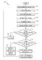
- FIG. 7 is an image projection process 700 , according to one example.
- the image projection process 700 is performed by a projector, such as the above described target tracking projector 204 , that is projecting one or more images to a head-mounted component, such as the head-mounted component 202 .
- the image projection process 700 begins by projecting, at 701 , illuminating light into a view of an image capturing device, such as the camera 230 described above.
- the illuminating light is projected by a marker search illuminator that is configured to project the illuminating light into an area that includes the view of the camera or other image capture device that is to capture a target image to be analyzed to determine the location of markers within the area.
- the image projection process 700 continues by capturing, at 702 , a target image that includes an image of the head-mounted component.
- the target image in one example is captured by a camera, such as the camera 230 described above.
- the image captured by the camera is taken with a view that has a characterized relationship to the projection of an image projector, thereby allowing the captured image to be analyzed to identify the physical relationship between objects in the image and a projector that projects an image.
- the capturing of a target image is combined with the projecting of the illuminating light with a marker search illuminator that is configured to project the illuminating light into the view of the camera or other image capture device that captures the target image.
- the image projection process 700 continues by identifying, at 704 , markers in the captured target image.
- the identified markers are able to be retroreflectors, as is described above. Identification of markers in the captured target images is described above with regards to the projector block diagram 400 .
- the image projection process 700 determines, at 706 , the projection angle to at least one image receiving area of a head-mounted component associated with the identified markers.
- the projection angle 310 is determined by analyzing the location of markers identified in the captured target image and applying stored characterizations of the physical relationship between the camera view 332 and the projecting lens 302 .
- the image projection process 700 also determines, at 708 , the pose angle of the least one image receiving area of a head-mounted component associated with the identified markers.
- the pose angle is a combination of the pitch angle 312 , the yaw angle 314 , and the roll angle 316 .
- the pose angle in one example is determined by analyzing the relationship between the location of each of the markers identified in the captured target image and applying stored characterizations of the physical relationship of the mounting of the markers on the head-mounted component to which the markers are mounted.
- the image projection process 700 determines, at 710 , the distance to the target, e.g., to the image receiving area of a head-mounted component.
- the determined distance corresponds to the distance 320 between the image projector 220 and the image receiving area 210 .
- the above determined parameters of projection angle 310 , pose angle and distance are applied to images projected by an image projector to ensure those images are squarely received on the image receiving area 210 .
- the image projection process 700 determines, at 712 , if the distance to the target, such as the image receiving area, pose angle, and projection angle of the image receiving area are within maximum values for those parameters.
- a projector operates to only project an image to head-mounted components that are within a defined area in front of the projector, and that have pose angle components that are all within a maximum variation of being perpendicular to a line connecting the projector and the head-mounted display.
- each of these parameters is able to have its own respective maximum value. If any of these parameters are in excess of the maximum value for that parameter, the image projection process 700 operates to ceases, at 714 , projecting the image.
- the image projection process 700 determines at 716 , if the distance to the target, pose angle, and projection angle are within maximum operating values for those parameters.
- a projector operates to progressively dim, such as by lowering the intensity of, defocusing, or otherwise modifying the projected image, when one or more of these determined parameters, i.e., at least one of the distance and orientation of the image receiving area or the projection angle, are determined to be within a defined respective range of their respective thresholds.
- the projected image is dimmed when one or more of the determined parameters exceed its maximum operating value but does not exceed the above described maximum value.
- Dimming by defocusing, or otherwise modifying the image, provides a wearer of a head-mounted component with feedback indicating that the user's head should be turned back towards the direction of the projection device. If it is determined that any one or more of the distance to the target, pose angle, and projection angle are not within maximum operating values for those parameters, the image is dimmed, at 718 , in proportion to the amount by which the parameter is above its maximum operating value.
- the image is adjusted, at 720 , according to the determined distance to the target, pose angle, and projection angle.
- the adjusted image is then projected, at 722 .
- An image is then captured, at 702 , and the image projection process 700 continues as described above.
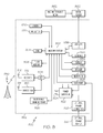
- FIG. 8 is a block diagram of an electronic device and associated components 800 in which the systems and methods disclosed herein may be implemented.
- an electronic device 852 is also a wireless two-way communication device with voice and data communication capabilities.
- Such electronic devices communicate with a wireless voice or data network 850 using a suitable wireless communications protocol.
- Wireless voice communications are performed using either an analog or digital wireless communication channel.
- Data communications allow the electronic device 852 to communicate with other computer systems via the Internet.
- Examples of electronic devices that are able to incorporate the above described systems and methods include, for example, a data messaging device, a two-way pager, a cellular telephone with data messaging capabilities, a wireless Internet appliance or a data communication device that may or may not include telephony capabilities.
- the illustrated electronic device 852 is an example electronic device that includes two-way wireless communications functions. Such electronic devices incorporate communication subsystem elements such as a wireless transmitter 810 , a wireless receiver 812 , and associated components such as one or more antenna elements 814 and 816 .
- a digital signal processor (DSP) 808 performs processing to extract data from received wireless signals and to generate signals to be transmitted.
- DSP digital signal processor
- the electronic device 852 includes a microprocessor 802 that controls the overall operation of the electronic device 852 .
- the microprocessor 802 interacts with the above described communications subsystem elements and also interacts with other device subsystems such as flash memory 806 , random access memory (RAM) 804 , auxiliary input/output (I/O) device 838 , data port 828 , display 834 , keyboard 836 , speaker 832 , microphone 830 , a short-range communications subsystem 820 , a power subsystem 822 , a camera 870 , a projector 872 , other subsystems, or combinations of these.
- flash memory 806 random access memory (RAM) 804
- I/O auxiliary input/output
- One or more power storage or supply elements are connected to a power subsystem 822 to provide power to the circuits of the electronic device 852 .
- the power subsystem 822 includes power distribution circuitry for providing power to the electronic device 852 and also contains battery charging circuitry to manage recharging the battery 824 (or circuitry to replenish power to another power storage element).
- the power subsystem 822 receives electrical power from external power supply 854 .
- the power subsystem 822 is able to be connected to the external power supply 854 through a dedicated external power connector (not shown) or through power connections within the data port 828 .
- the power subsystem 822 includes a battery monitoring circuit that is operable to provide a status of one or more battery status indicators, such as remaining capacity, temperature, voltage, electrical current consumption, and the like, to various components of the electronic device 852 .
- the projector 872 is similar in one example to the above described target tracking projector 204 .
- the projector 872 is able to receive image data from the microprocessor 802 and project images defined by that data to, for example, an image receiving area such as the above described image receiving area 210 of the head-mounted component 202 .
- the camera 870 which in one example is equivalent to the above described camera 230 , is able to capture images with a view angle that has a known relationship to the projection of the projector 872 .
- the camera 870 provides data defining captured images to the microprocessor 802 for image processing and, for example, identification of images of the markers within the captured image.
- the microprocessor 802 in one example determines adjustments to be applied to image data that is provided to the projector 872 so as to cause the projected images to be squarely received.
- the data port 828 is able to support data communications between the electronic device 852 and other devices through various modes of data communications, such as high speed data transfers over an optical communications circuits.
- Data port 828 is able to support communications with, for example, an external computer or other device.
- the data port 828 is able to include electrical power connections to provide externally provided electrical power to the electronic device 852 , deliver electrical power from the electronic device 852 to other externally connected devices, or both.
- Data port 828 of, for example, an electronic accessory is able to provide power to an electronic circuit, such as microprocessor 802 , and support exchanging data between the microprocessor 802 and a remote electronic device that is connected through the data port 828 .
- Data communication through data port 828 enables a user to set preferences through the external device or through a software application and extends the capabilities of the device by enabling information or software exchange through direct connections between the electronic device 852 and external data sources rather then via a wireless data communication network.
- the data port 828 provides power to the power subsystem 822 to charge the battery 824 or to supply power to the electronic circuits, such as microprocessor 802 , of the electronic device 852 .
- Operating system software used by the microprocessor 802 is stored in flash memory 806 . Further examples are able to use a battery backed-up RAM or other non-volatile storage data elements to store operating systems, other executable programs, or both.
- the operating system software, device application software, or parts thereof, are able to be temporarily loaded into volatile data storage such as RAM 804 . Data received via wireless communication signals or through wired communications are also able to be stored to RAM 804 .
- the microprocessor 802 in addition to its operating system functions, is able to execute software applications on the electronic device 852 .
- PIM personal information manager
- Further applications may also be loaded onto the electronic device 852 through, for example, the wireless network 850 , an auxiliary I/O device 838 , Data port 828 , short-range communications subsystem 820 , or any combination of these interfaces. Such applications are then able to be installed by a user in the RAM 804 or a non-volatile store for execution by the microprocessor 802 .
- a received signal such as a text message or web page download is processed by the communication subsystem, including wireless receiver 812 and wireless transmitter 810 , and communicated data is provided the microprocessor 802 , which is able to further process the received data for output to the display 834 , or alternatively, to an auxiliary I/O device 838 or the Data port 828 .
- a user of the electronic device 852 may also compose data items, such as e-mail messages, using the keyboard 836 , which is able to include a complete alphanumeric keyboard or a telephone-type keypad, in conjunction with the display 834 and possibly an auxiliary I/O device 838 . Such composed items are then able to be transmitted over a communication network through the communication subsystem.
- voice communications For voice communications, overall operation of the electronic device 852 is substantially similar, except that received signals are generally provided to a speaker 832 and signals for transmission are generally produced by a microphone 830 .
- Alternative voice or audio I/O subsystems such as a voice message recording subsystem, may also be implemented on the electronic device 852 .
- voice or audio signal output is generally accomplished primarily through the speaker 832
- the display 834 may also be used to provide an indication of the identity of a calling party, the duration of a voice call, or other voice call related information, for example.
- one or more particular functions associated with a subsystem circuit may be disabled, or an entire subsystem circuit may be disabled. For example, if the battery temperature is low, then voice functions may be disabled, but data communications, such as e-mail, may still be enabled over the communication subsystem.
- a short-range communications subsystem 820 provides for data communication between the electronic device 852 and different systems or devices, which need not necessarily be similar devices.
- the short-range communications subsystem 820 includes an infrared device and associated circuits and components or a Radio Frequency based communication module such as one supporting Bluetooth® communications, to provide for communication with similarly-enabled systems and devices, including the data file transfer communications described above.
- a media reader 860 is able to be connected to an auxiliary I/O device 838 to allow, for example, loading computer readable program code of a computer program product into the electronic device 852 for storage into flash memory 806 .
- a media reader 860 is an optical drive such as a CD/DVD drive, which may be used to store data to and read data from a computer readable medium or storage product such as computer readable storage media 862 .
- suitable computer readable storage media include optical storage media such as a CD or DVD, magnetic media, or any other suitable data storage device.
- Media reader 860 is alternatively able to be connected to the electronic device through the Data port 828 or computer readable program code is alternatively able to be provided to the electronic device 852 through the wireless network 850 .
- the present subject matter can be realized in hardware, software, or a combination of hardware and software.
- a system can be realized in a centralized fashion in one computer system, or in a distributed fashion where different elements are spread across several interconnected computer systems. Any kind of computer system—or other apparatus adapted for carrying out the methods described herein—is suitable.
- a typical combination of hardware and software could be a general purpose computer system with a computer program that, when being loaded and executed, controls the computer system such that it carries out the methods described herein.
- Computer program in the present context means any expression, in any language, code or notation, of a set of instructions intended to cause a system having an information processing capability to perform a particular function either directly or after either or both of the following a) conversion to another language, code or, notation; and b) reproduction in a different material form.
- Each computer system may include, inter alia, one or more computers and at least a computer readable medium allowing a computer to read data, instructions, messages or message packets, and other computer readable information from the computer readable medium.
- the computer readable medium may include computer readable storage medium embodying non-volatile memory, such as read-only memory (ROM), flash memory, disk drive memory, CD-ROM, and other permanent storage. Additionally, a computer medium may include volatile storage such as RAM, buffers, cache memory, and network circuits.
- the computer readable medium may comprise computer readable information in a transitory state medium such as a network link and/or a network interface, including a wired network or a wireless network, that allow a computer to read such computer readable information.
Landscapes
- Physics & Mathematics (AREA)
- Engineering & Computer Science (AREA)
- General Physics & Mathematics (AREA)
- Theoretical Computer Science (AREA)
- Optics & Photonics (AREA)
- General Engineering & Computer Science (AREA)
- Human Computer Interaction (AREA)
- Controls And Circuits For Display Device (AREA)
Abstract
Description
Claims (13)
Priority Applications (1)
| Application Number | Priority Date | Filing Date | Title |
|---|---|---|---|
| US13/767,360 US9507147B2 (en) | 2013-02-14 | 2013-02-14 | Wearable display system with detached projector |
Applications Claiming Priority (1)
| Application Number | Priority Date | Filing Date | Title |
|---|---|---|---|
| US13/767,360 US9507147B2 (en) | 2013-02-14 | 2013-02-14 | Wearable display system with detached projector |
Publications (2)
| Publication Number | Publication Date |
|---|---|
| US20140225915A1 US20140225915A1 (en) | 2014-08-14 |
| US9507147B2 true US9507147B2 (en) | 2016-11-29 |
Family
ID=51297166
Family Applications (1)
| Application Number | Title | Priority Date | Filing Date |
|---|---|---|---|
| US13/767,360 Active 2034-11-28 US9507147B2 (en) | 2013-02-14 | 2013-02-14 | Wearable display system with detached projector |
Country Status (1)
| Country | Link |
|---|---|
| US (1) | US9507147B2 (en) |
Cited By (1)
| Publication number | Priority date | Publication date | Assignee | Title |
|---|---|---|---|---|
| US20240262059A1 (en) * | 2015-09-03 | 2024-08-08 | 3M Innovative Properties Company | Shaped reflective polarizer and optical system including same |
Families Citing this family (24)
| Publication number | Priority date | Publication date | Assignee | Title |
|---|---|---|---|---|
| CN103353677B (en) | 2013-06-28 | 2015-03-11 | 北京智谷睿拓技术服务有限公司 | Imaging device and method thereof |
| CN103353663B (en) | 2013-06-28 | 2016-08-10 | 北京智谷睿拓技术服务有限公司 | Imaging adjusting apparatus and method |
| CN103353667B (en) | 2013-06-28 | 2015-10-21 | 北京智谷睿拓技术服务有限公司 | Imaging adjustment Apparatus and method for |
| KR102191867B1 (en) * | 2013-07-10 | 2020-12-16 | 엘지전자 주식회사 | Apparatus and Method for Head Mounted Display Device with multiple user interface formats |
| US9113036B2 (en) | 2013-07-17 | 2015-08-18 | Ebay Inc. | Methods, systems, and apparatus for providing video communications |
| CN103431840B (en) | 2013-07-31 | 2016-01-20 | 北京智谷睿拓技术服务有限公司 | Eye optical parameter detecting system and method |
| CN103424891B (en) | 2013-07-31 | 2014-12-17 | 北京智谷睿拓技术服务有限公司 | Imaging device and method |
| CN103439801B (en) | 2013-08-22 | 2016-10-26 | 北京智谷睿拓技术服务有限公司 | Sight protectio imaging device and method |
| CN103431980A (en) | 2013-08-22 | 2013-12-11 | 北京智谷睿拓技术服务有限公司 | Eyesight protection imaging system and method |
| CN103500331B (en) | 2013-08-30 | 2017-11-10 | 北京智谷睿拓技术服务有限公司 | Based reminding method and device |
| CN103605208B (en) | 2013-08-30 | 2016-09-28 | 北京智谷睿拓技术服务有限公司 | content projection system and method |
| CN103558909B (en) * | 2013-10-10 | 2017-03-29 | 北京智谷睿拓技术服务有限公司 | Interaction projection display packing and interaction projection display system |
| KR102154912B1 (en) * | 2013-10-11 | 2020-09-11 | 인터디지탈 패튼 홀딩스, 인크 | Gaze-driven augmented reality |
| US20160178906A1 (en) * | 2014-12-19 | 2016-06-23 | Intel Corporation | Virtual wearables |
| US9659411B2 (en) | 2015-01-14 | 2017-05-23 | Oculus Vr, Llc | Passive locators for a virtual reality headset |
| TWI620098B (en) * | 2015-10-07 | 2018-04-01 | 財團法人資訊工業策進會 | Head mounted device and guiding method |
| US10025093B2 (en) | 2016-04-13 | 2018-07-17 | Microsoft Technology Licensing, Llc | Waveguide-based displays with exit pupil expander |
| US10009586B2 (en) * | 2016-11-11 | 2018-06-26 | Christie Digital Systems Usa, Inc. | System and method for projecting images on a marked surface |
| JP6784944B2 (en) * | 2018-03-26 | 2020-11-18 | カシオ計算機株式会社 | Projection control device, marker detection method and program |
| CN110286754B (en) * | 2019-06-11 | 2022-06-24 | Oppo广东移动通信有限公司 | Projection method and related equipment based on eye tracking |
| US10885819B1 (en) * | 2019-08-02 | 2021-01-05 | Harman International Industries, Incorporated | In-vehicle augmented reality system |
| EP4010783B1 (en) * | 2019-08-08 | 2025-10-01 | Essilor International | Systems, devices and methods using spectacle lens and frame |
| US11082685B2 (en) | 2019-11-05 | 2021-08-03 | Universal City Studios Llc | Head-mounted device for displaying projected images |
| FR3156566B1 (en) * | 2023-12-07 | 2025-11-07 | Safran Electronics & Defense | Vehicle-mounted tracking system and associated method |
Citations (8)
| Publication number | Priority date | Publication date | Assignee | Title |
|---|---|---|---|---|
| US5638208A (en) | 1996-07-23 | 1997-06-10 | Evans & Sutherland Computer Corporation | Projection screen with retro-reflective calibration points, placement tool and method |
| US5889550A (en) * | 1996-06-10 | 1999-03-30 | Adaptive Optics Associates, Inc. | Camera tracking system |
| US5889625A (en) | 1997-05-21 | 1999-03-30 | Raytheon Company | Chromatic aberration correction for display systems |
| EP0977071A1 (en) | 1998-07-27 | 2000-02-02 | Mixed Reality Systems Laboratory Inc. | Image observing apparatus |
| US20080291342A1 (en) * | 2007-05-21 | 2008-11-27 | Funai Electric Co., Ltd. | Projection Type Video Display Apparatus |
| US20090015799A1 (en) | 2007-04-26 | 2009-01-15 | Vincent Luciano | Projection system |
| US20110074837A1 (en) | 2009-09-30 | 2011-03-31 | Brother Kogyo Kabushiki Kaisha | Image display device |
| US20130342572A1 (en) * | 2012-06-26 | 2013-12-26 | Adam G. Poulos | Control of displayed content in virtual environments |
-
2013
- 2013-02-14 US US13/767,360 patent/US9507147B2/en active Active
Patent Citations (8)
| Publication number | Priority date | Publication date | Assignee | Title |
|---|---|---|---|---|
| US5889550A (en) * | 1996-06-10 | 1999-03-30 | Adaptive Optics Associates, Inc. | Camera tracking system |
| US5638208A (en) | 1996-07-23 | 1997-06-10 | Evans & Sutherland Computer Corporation | Projection screen with retro-reflective calibration points, placement tool and method |
| US5889625A (en) | 1997-05-21 | 1999-03-30 | Raytheon Company | Chromatic aberration correction for display systems |
| EP0977071A1 (en) | 1998-07-27 | 2000-02-02 | Mixed Reality Systems Laboratory Inc. | Image observing apparatus |
| US20090015799A1 (en) | 2007-04-26 | 2009-01-15 | Vincent Luciano | Projection system |
| US20080291342A1 (en) * | 2007-05-21 | 2008-11-27 | Funai Electric Co., Ltd. | Projection Type Video Display Apparatus |
| US20110074837A1 (en) | 2009-09-30 | 2011-03-31 | Brother Kogyo Kabushiki Kaisha | Image display device |
| US20130342572A1 (en) * | 2012-06-26 | 2013-12-26 | Adam G. Poulos | Control of displayed content in virtual environments |
Non-Patent Citations (3)
| Title |
|---|
| European Search Report dated Oct. 28, 2013 for European Application No. 13155305. |
| FPS, Flexible Picture Systems, Image AnyPlace, Video/Graphics Scaler with Geometry Correction and Optional Edge Blending, www.flexiblepicturesystems.com, Oct. 2008. |
| Klepper, S., "Augmented Reality-Display Systems," A survey by Sebastian Klepper, TU Muenchen, Apr. 7, 2007, Sebastian.Klepper@myTUM.de. |
Cited By (1)
| Publication number | Priority date | Publication date | Assignee | Title |
|---|---|---|---|---|
| US20240262059A1 (en) * | 2015-09-03 | 2024-08-08 | 3M Innovative Properties Company | Shaped reflective polarizer and optical system including same |
Also Published As
| Publication number | Publication date |
|---|---|
| US20140225915A1 (en) | 2014-08-14 |
Similar Documents
| Publication | Publication Date | Title |
|---|---|---|
| US9507147B2 (en) | Wearable display system with detached projector | |
| US11536964B2 (en) | Head-mounted display apparatus, display control method, and computer program | |
| EP3330771B1 (en) | Display apparatus and method of displaying using focus and context displays | |
| US20230314808A1 (en) | Systems With Displays and Sensor-Hiding Structures | |
| CN114531951B (en) | Automatic video capture and compositing system | |
| CN110060614B (en) | Head-mounted display device, control method thereof, and display system | |
| CN109814719B (en) | Method and equipment for displaying information based on wearing glasses | |
| EP3371640A1 (en) | Display of binocular overlapping images in a head mounted display | |
| JP2016533565A (en) | Orientation and visualization of virtual objects | |
| KR20160014507A (en) | Method for displayin image by head mounted display device and head maounted display device thereof | |
| US12438400B2 (en) | Wearable electronic device and electronic device charging the same | |
| US12002392B2 (en) | Eyewear projector brightness control | |
| US12542979B2 (en) | Method of removing interference and electronic device performing the method | |
| US9319980B1 (en) | Efficient digital image distribution | |
| GB2548151A (en) | Head-mountable display | |
| EP2768224B1 (en) | Wearable display system with detached projector | |
| US20230085063A1 (en) | Vcsel chip for generation of linear structured light patterns and flood illumination | |
| KR20240020629A (en) | Method and apparatus for determining content to instruct an ar device to display | |
| CN211528904U (en) | Transmission type geometric holographic display system | |
| US12474615B2 (en) | Electronic device including electrochromic device and method of controlling the electronic device | |
| KR20240030881A (en) | Method for outputting a virtual content and an electronic device supporting the same | |
| KR20230045928A (en) | Electronic device for providing augmented reality service and operating method thereof | |
| KR102940191B1 (en) | Augmented reality wearable electronic device including camera | |
| US20260052230A1 (en) | Electronic Devices with Displays Having Non-Uniform Scaling | |
| US20250181158A1 (en) | Display module control method and electronic device for carrying out same |
Legal Events
| Date | Code | Title | Description |
|---|---|---|---|
| AS | Assignment |
Owner name: RESEARCH IN MOTION DEUTSCHLAND GMBH, GERMANY Free format text: ASSIGNMENT OF ASSIGNORS INTEREST;ASSIGNORS:THEIMER, WOLFGANG MICHAEL;MEIERLING, KLAUS-DIETER;REEL/FRAME:030148/0496 Effective date: 20130321 |
|
| AS | Assignment |
Owner name: RESEARCH IN MOTION LIMITED, ONTARIO Free format text: ASSIGNMENT OF ASSIGNORS INTEREST;ASSIGNOR:RESEARCH IN MOTION DEUTSCHLAND GMBH;REEL/FRAME:030387/0505 Effective date: 20130429 |
|
| AS | Assignment |
Owner name: BLACKBERRY LIMITED, ONTARIO Free format text: CHANGE OF NAME;ASSIGNOR:RESEARCH IN MOTION LIMITED;REEL/FRAME:038087/0963 Effective date: 20130709 |
|
| STCF | Information on status: patent grant |
Free format text: PATENTED CASE |
|
| MAFP | Maintenance fee payment |
Free format text: PAYMENT OF MAINTENANCE FEE, 4TH YEAR, LARGE ENTITY (ORIGINAL EVENT CODE: M1551); ENTITY STATUS OF PATENT OWNER: LARGE ENTITY Year of fee payment: 4 |
|
| AS | Assignment |
Owner name: MALIKIE INNOVATIONS LIMITED, IRELAND Free format text: ASSIGNMENT OF ASSIGNORS INTEREST;ASSIGNOR:BLACKBERRY LIMITED;REEL/FRAME:064104/0103 Effective date: 20230511 |
|
| AS | Assignment |
Owner name: MALIKIE INNOVATIONS LIMITED, IRELAND Free format text: NUNC PRO TUNC ASSIGNMENT;ASSIGNOR:BLACKBERRY LIMITED;REEL/FRAME:064271/0199 Effective date: 20230511 |
|
| MAFP | Maintenance fee payment |
Free format text: PAYMENT OF MAINTENANCE FEE, 8TH YEAR, LARGE ENTITY (ORIGINAL EVENT CODE: M1552); ENTITY STATUS OF PATENT OWNER: LARGE ENTITY Year of fee payment: 8 |