US950561A - Alcohol-lamp. - Google Patents
Alcohol-lamp. Download PDFInfo
- Publication number
- US950561A US950561A US42260808A US1908422608A US950561A US 950561 A US950561 A US 950561A US 42260808 A US42260808 A US 42260808A US 1908422608 A US1908422608 A US 1908422608A US 950561 A US950561 A US 950561A
- Authority
- US
- United States
- Prior art keywords
- tube
- blow
- pipe
- lamp
- wick
- Prior art date
- Legal status (The legal status is an assumption and is not a legal conclusion. Google has not performed a legal analysis and makes no representation as to the accuracy of the status listed.)
- Expired - Lifetime
Links
Images
Classifications
-
- F—MECHANICAL ENGINEERING; LIGHTING; HEATING; WEAPONS; BLASTING
- F23—COMBUSTION APPARATUS; COMBUSTION PROCESSES
- F23D—BURNERS
- F23D99/00—Subject matter not provided for in other groups of this subclass
- F23D99/002—Burners specially adapted for specific applications
- F23D99/004—Burners specially adapted for specific applications for use in particular heating operations
Definitions
- the object of my invention is to provide a lamp for usey of jewelers, dentists, and others, which shall possess all ofthe advantageous features of a lamp for use with Va blow pi e, ⁇ but also 'provide a central ⁇ forced dra t lamp, with an adjustable nozzleiof such a character as to permit the variation lof the size of the flame issuing therefrom, and alsoto Aprovide an adjustable external blow pipe for use in connection therel with.
- Figure l illustrates a side elevation of my improved lamp.
- Fig. ⁇ 2 illustrates a vertical section of the same.
- Fig. 3f is a top plan View; and
- V is an enlarged Vertical section ot the jet and adjustablefmtcmor nozzle.
- Thebodyor reservoir o of my improvedV lamp iscyl-indrical in form, but may be of any desired shape or configuration.
- ⁇ illustrated it consists of the cylindrical shell having secured thereto, in an convement manner, asby soldering-the t anged bottom c, and the top or cover (l. Extending -centrally from the bottom, and rigidlyconnected therewith, is'a small chamber e, to
- the chamber c and provided at ⁇ its exterior end with the h'ead k.
- I provide the cylindrical 4thimble Z, .fitting rather closely the upper end of the tube f, and connected to the rod h by means ot' a pin m.
- the u'pperend 'of this thimble is provided ⁇ with a plurality of fine apertures, so that when air is forced through the tubes y and it will lemerge through said aperturesiu fine jets.
- the internal diameter of thethimble l is 'somewhat larger than the diameter of the rod li, so that there will be free passage through the tube into the thimble l.
- the tube p may be secured into the headV (l by any convenient means, as ⁇ by vmeans yot' the screw thimble q, screwed intothe central ap-V -the purpose of filling.
- the thimble s is also provided with a small bent tube t, which ex-v tends through the top f the cap in order to provide a vent.
- Athe brackets u, u Located at the side of the chamber a are Athe brackets u, u, for the purpose of carrying the external blow pipe o over the upper end of which is the telescoping bent tube w, having its upper end directed toward the tube'p, and vertically adjustable so as to permit a jet of air to be directed to any part of the flame from the wick o.
- a telescoping nozzle a which may be adjusted upon sald bent portion toward and away from the llame, and as a a guide for the lamp
- the outer convenient means for providing such :1d-1vv justment, l secure the bail 3/ to the sides of said nozzle a', so that suchbail may be used as a handle for pushing the nozzle fr out and in.
- a fuel reservoir a tubular Wick supportingv blow pipe rigidly secured therein extending from the bottom of said reservoirthrough the top or cover thereof, a. nozzle at the mouth of said blow pipe and means at the lower end of said blow pipe for adjustably securing said nozzle in the mouth of said blow pipe.
- a fluid fuel lamp In a fluid fuel lamp, the combination of a fuel reservoir, a central wick supporting blow-pipe rigidly secured to the bottom of said reservoir, a tubularwick mounted upon said blow-pipe, a lateral supply pipe leading from the exteriorof the reservoir and communicating with said blow-pipe and a vertically adjustable nozzle located in the mouth of :said blow-pipe.
- a fluid fuel lamp the combination of a fuel reservoir, ay central wick supportingv blow-pipe having a tubular Wick mounted thereon, an adjustable nozzle located in the upper end ofsaid blow-pipe and external.
Landscapes
- Engineering & Computer Science (AREA)
- Chemical & Material Sciences (AREA)
- Combustion & Propulsion (AREA)
- Mechanical Engineering (AREA)
- General Engineering & Computer Science (AREA)
- Non-Portable Lighting Devices Or Systems Thereof (AREA)
Description
SEAMAN. ALCOHOL LAMP.
APPLIOATION FILED MAB.. 23, 1908.
Patented Mall'. 1, 1910.
www Arron/vin?.
fa y WIT/VESSES:
UNITED STATES PATENT OFFICE.
JAMES H. SEAMAN, OF PRINCEQBAY, NEW YORr Specification of Letters Patent.
Application filed March 23. y1908.
ALCOHOL-LAMP.
.Patented Mar. 1. 1910. serial' No. 422,608.
asy will lenable others skilled in the art toy which it pertains `to make, construct'. and use the same. l'
The object of my invention is to provide a lamp for usey of jewelers, dentists, and others, which shall possess all ofthe advantageous features of a lamp for use with Va blow pi e,`but also 'provide a central `forced dra t lamp, with an adjustable nozzleiof such a character as to permit the variation lof the size of the flame issuing therefrom, and alsoto Aprovide an adjustable external blow pipe for use in connection therel with. A
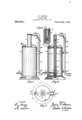
In the accompanying drawings forming a part of *this specification, Figure l illustrates a side elevation of my improved lamp. Fig.` 2 illustrates a vertical section of the same. Fig. 3f is a top plan View; and Fig. 4
V is an enlarged Vertical section ot the jet and adjustablefmtcmor nozzle.
In the accompan 7lngl drawings, like letters of reference re er to like parts'throughout. .j V
Thebodyor reservoir o of my improvedV lamp iscyl-indrical in form, but may be of any desired shape or configuration. As
` illustrated, it consists of the cylindrical shell having secured thereto, in an convement manner, asby soldering-the t anged bottom c, and the top or cover (l. Extending -centrally from the bottom, and rigidlyconnected therewith, is'a small chamber e, to
the upper end ofwhich is rigidly 1connected the tube f, said tube" extending out through anjaperture in the top d to a suitable height. Extending laterally'lnto the chamber e yfrom the exteriorv of the' shell b, is the'nlet port f), which is secured to the shell by any con-l lvenient means,so as to form a liquid tight and tu e f is a solid ro joint. The connection of the tube g w1th the chamber@ is also made liquid tight, so as to form a'v continuous passage from the tube g'to the u per end ofthe tube f. Extendin centraily throu h the chamber e, h, screw-threaded at the lower'extremity into the shank z',
the chamber c and provided at` its exterior end with the h'ead k.
At the upper end of the rod i, I provide the cylindrical 4thimble Z, .fitting rather closely the upper end of the tube f, and connected to the rod h by means ot' a pin m. The u'pperend 'of this thimble is provided `with a plurality of fine apertures, so that when air is forced through the tubes y and it will lemerge through said aperturesiu fine jets. It will be noted that the internal diameter of thethimble l is 'somewhat larger than the diameter of the rod li, so that there will be free passage through the tube into the thimble l.
In order to limit' the, vertical adjustment of the thimble l at the mouth of the tube f, I provide a small stopv nut n, upon the lower screw-threaded portion of the rod i, so `that in screwing down the rod i, said nut 'n will limit its downward movement, while the head k willI limit thc upward movenumt' of the rod h and with it the thimble Z. Surrounding the tube f is the tubular lamp wick 0, passing through the aperture in the cover d. In order to form wick '0, I provide the cover d with a tubular extension p, projecting above the cover l to a heightequal to the height of thc tube j'. The tube p may be secured into the headV (l by any convenient means, as `by vmeans yot' the screw thimble q, screwed intothe central ap-V -the purpose of filling. The thimble s is also provided with a small bent tube t, which ex-v tends through the top f the cap in order to provide a vent.
j Located at the side of the chamber a are Athe brackets u, u, for the purpose of carrying the external blow pipe o over the upper end of which is the telescoping bent tube w, having its upper end directed toward the tube'p, and vertically adjustable so as to permit a jet of air to be directed to any part of the flame from the wick o. end of the bent portion of the tube n', is provided with a telescoping nozzle a, which may be adjusted upon sald bent portion toward and away from the llame, and as a a guide for the lamp The outer convenient means for providing such :1d-1vv justment, l secure the bail 3/ to the sides of said nozzle a', so that suchbail may be used as a handle for pushing the nozzle fr out and in.
With the construction just described, I am able to use either the external blow pipe or the internal blow pipe. By connecting the lower bent end of the tube t* With a rubber tube a, through which the blast of air 'may be sent, I make an external blow pipe lamp, or if desired to make it an internal blow pipe lalnp, the rubber tube a is transferred from the tube o to the tube g, and the blast sent therethrough to the chamber e, and thence to the tube whence it emerges through the thimble Z in the tine jets heretofore' referred to.
By the `adjustment of the central blow pipe, through the Vertical movement of the thimble Z, at the top of the tube f, I am able to concentrate the central draft to any degree desirable in use,` as for example, when the same isadjusted to its lowermost position, the flame is broadened materially and when the thimble Z is extended from the tube f, the flame is contracted so as to draw the flame to a fine oint. Between these extremes of broad jet and tine pointed jet, any degree of adjustment may behad.
' I find in practice that when the mouth of the tube f is flared outwardly as at j, there is no tendency for the wick 0 to overlap and obstruct the fine air passages 'through the nozzleZ. IVhen this Haring of the tube f is done, the mouth of the tube p is also slightly iiared as at p', so that there will be no obstruction to the 'free raising and lowering ofthe wick 0.
I claim v: e
l. In an alcohol lamp, the combination of a reservoir with a rigidly fixed blow pipe, a tubular wick upon the exterior of said blow pipe and means for adjusting the draft through said blow pipe at its exit therefrom.
2. -In an alcohol lamp, the combination of a a fuel reservoir, a central wick supporting blow pipe rigidly secured therein and an ad- -f justable nozzle located in the mouth of said blow pipe.
95o, sei
a fuel reservoir, a tubular Wick supportingv blow pipe rigidly secured therein extending from the bottom of said reservoirthrough the top or cover thereof, a. nozzle at the mouth of said blow pipe and means at the lower end of said blow pipe for adjustably securing said nozzle in the mouth of said blow pipe.
In a fluid fuel lamp, the combination of a fuel reservoir, a central wick supporting blow-pipe rigidly secured to the bottom of said reservoir, a tubularwick mounted upon said blow-pipe, a lateral supply pipe leading from the exteriorof the reservoir and communicating with said blow-pipe and a vertically adjustable nozzle located in the mouth of :said blow-pipe.
6. In a fluid fuel lamp, the combination of a fuel reservoir, ay central wick supportingv blow-pipe having a tubular Wick mounted thereon, an adjustable nozzle located in the upper end ofsaid blow-pipe and external.
said nozzle longitudinally in said blow-pipe.
7'. In an alcohol lamp, the combination of a fuel reservoir, a central wick supporting blow-pipe rigidly secured to the bottom ofthe reservoir and extending through the top thereof, a lateral supply pipe connected with said blow-pipe and extendingvwithout ysaid reservoir, a tubular wick. surrounding said blow-pipe, a tubular extension secured to the reservoir top and 'surrounding said wick and means for adjusting an adjustable nozzle located in the upper end of said blow-pipe and loiigitudinally adj ustable therein.
This specification signed and witnessed this 21st day of March 1908.
` JAMEs H. sEAMAN. lVitnesses:
Louis M. SANDERS, C. A. ALLISTON.
Priority Applications (1)
| Application Number | Priority Date | Filing Date | Title |
|---|---|---|---|
| US42260808A US950561A (en) | 1908-03-23 | 1908-03-23 | Alcohol-lamp. |
Applications Claiming Priority (1)
| Application Number | Priority Date | Filing Date | Title |
|---|---|---|---|
| US42260808A US950561A (en) | 1908-03-23 | 1908-03-23 | Alcohol-lamp. |
Publications (1)
| Publication Number | Publication Date |
|---|---|
| US950561A true US950561A (en) | 1910-03-01 |
Family
ID=3018974
Family Applications (1)
| Application Number | Title | Priority Date | Filing Date |
|---|---|---|---|
| US42260808A Expired - Lifetime US950561A (en) | 1908-03-23 | 1908-03-23 | Alcohol-lamp. |
Country Status (1)
| Country | Link |
|---|---|
| US (1) | US950561A (en) |
-
1908
- 1908-03-23 US US42260808A patent/US950561A/en not_active Expired - Lifetime
Similar Documents
| Publication | Publication Date | Title |
|---|---|---|
| US638481A (en) | Atomizer and nebulizer. | |
| US622245A (en) | luttrell | |
| US576259A (en) | Photo-litho | |
| US757157A (en) | Atomizer. | |
| US743313A (en) | Oxyhydrogen-blowpipe. | |
| US657036A (en) | Cactus-burner. | |
| US469108A (en) | Lewis b | |
| US1049848A (en) | Gas-burner. | |
| US36237A (en) | Improvement in mica chimneys for lamps | |
| US955938A (en) | Atomizer. | |
| US769741A (en) | Atomizer. | |
| US495280A (en) | thomas | |
| US1481114A (en) | ashby | |
| US541408A (en) | Fourth to frederick | |
| US1905617A (en) | Plumber's furnace | |
| US46485A (en) | Improvement in ejectors for oil-wells | |
| US791260A (en) | Valve-regulating device for gas-burners. | |
| US1028976A (en) | Hydrocarbon-burner. | |
| US336418A (en) | Osoae d | |
| US763977A (en) | Ventilator. | |
| US687316A (en) | Dental blowpipe and lamp. | |
| US257857A (en) | James l | |
| US565729A (en) | Siphon | |
| US657127A (en) | Vapor-burning lamp. | |
| US1121519A (en) | Alcohol-lamp. |