US9503653B2 - Method for determining attitude of star sensor based on rolling shutter imaging - Google Patents
Method for determining attitude of star sensor based on rolling shutter imaging Download PDFInfo
- Publication number
- US9503653B2 US9503653B2 US13/983,979 US201313983979A US9503653B2 US 9503653 B2 US9503653 B2 US 9503653B2 US 201313983979 A US201313983979 A US 201313983979A US 9503653 B2 US9503653 B2 US 9503653B2
- Authority
- US
- United States
- Prior art keywords
- star
- navigation
- sensor
- image
- attitude
- Prior art date
- Legal status (The legal status is an assumption and is not a legal conclusion. Google has not performed a legal analysis and makes no representation as to the accuracy of the status listed.)
- Active, expires
Links
Images


Classifications
-
- H04N5/2353—
-
- G—PHYSICS
- G01—MEASURING; TESTING
- G01S—RADIO DIRECTION-FINDING; RADIO NAVIGATION; DETERMINING DISTANCE OR VELOCITY BY USE OF RADIO WAVES; LOCATING OR PRESENCE-DETECTING BY USE OF THE REFLECTION OR RERADIATION OF RADIO WAVES; ANALOGOUS ARRANGEMENTS USING OTHER WAVES
- G01S3/00—Direction-finders for determining the direction from which infrasonic, sonic, ultrasonic or electromagnetic waves, or particle emission, not having a directional significance, are being received
- G01S3/78—Direction-finders for determining the direction from which infrasonic, sonic, ultrasonic or electromagnetic waves, or particle emission, not having a directional significance, are being received using electromagnetic waves other than radio waves
- G01S3/782—Systems for determining direction or deviation from predetermined direction
- G01S3/785—Systems for determining direction or deviation from predetermined direction using adjustment of orientation of directivity characteristics of a detector or detector system to give a desired condition of signal derived from that detector or detector system
- G01S3/786—Systems for determining direction or deviation from predetermined direction using adjustment of orientation of directivity characteristics of a detector or detector system to give a desired condition of signal derived from that detector or detector system the desired condition being maintained automatically
- G01S3/7867—Star trackers
-
- H—ELECTRICITY
- H04—ELECTRIC COMMUNICATION TECHNIQUE
- H04N—PICTORIAL COMMUNICATION, e.g. TELEVISION
- H04N23/00—Cameras or camera modules comprising electronic image sensors; Control thereof
- H04N23/60—Control of cameras or camera modules
- H04N23/68—Control of cameras or camera modules for stable pick-up of the scene, e.g. compensating for camera body vibrations
- H04N23/689—Motion occurring during a rolling shutter mode
-
- H—ELECTRICITY
- H04—ELECTRIC COMMUNICATION TECHNIQUE
- H04N—PICTORIAL COMMUNICATION, e.g. TELEVISION
- H04N23/00—Cameras or camera modules comprising electronic image sensors; Control thereof
- H04N23/70—Circuitry for compensating brightness variation in the scene
- H04N23/73—Circuitry for compensating brightness variation in the scene by influencing the exposure time
-
- H04N5/2329—
Definitions
- Embodiments of the present disclosure generally relate to the attitude sensor field, and more particularly relate to a method for determining an attitude of a star sensor based on a rolling shutter imaging.
- the star sensor is an absolute attitude measure system referring to the celestial body azimuth, having the features of high measure precision, no drift and long working life. Meanwhile, the star sensor is a basal and pivotal part of a spacecraft, and is an important part of the space technology development. The star sensor plays an irreplaceable important role in the space application like earth-pointing remote sensing, deep space exploration, space attack-defense and so on. The star sensor has the huge economic and social benefits and also has important strategic significance. Presently, the star sensor is universally considered to be a sensor having the highest attitude measure precision in a satellite, the pointing axis accuracy of the star sensor may reach 10′′, and the update rate of the star sensor may be 1-5 Hz.
- the conventional star sensor adopts large area array and frame image processing mode, which makes the update rate low and the dynamic property poor. This has become the main technical barrier in the development of the star sensor.
- the conventional star sensor cannot satisfy the increasing requirement of the fast development of high resolution earth-pointing imaging, high-precision mapping and other space missions, and this has become an important bottle neck to restrict the advancement of the spaceflight field, more particularly the space remote sensing technology.
- Embodiments of the present disclosure seek to solve at least one of the problems existing in the prior art to at least some extent.
- a method for determining an attitude of a star sensor based on a rolling shutter imaging comprises steps of: S 1 : optimizing a relation among an exposure time t Int , a line readout time t rd , an interline integral interval time and t ri frame processing time t Fp of an image for the rolling shutter imaging by using a rolling shutter model of an image sensor in the star sensor based on a line; S 2 : predicting and extracting locations of M navigation stars comprised in a star map in the star sensor according to the optimized relation among the exposure time t Int , the line readout time t rd , the interline integral interval t ri and the frame processing time t Fp , in which the location of each navigation star is used to determine a line number of the each navigation star in the star sensor; and S 3 : updating an attitude matrix and an angular velocity of the star sensor according to the locations of the navigation stars and based on a single star
- the imaging parameter optimization method of star sensor based on the rolling shutter it is capable to achieve accurate separation of the exposure moments of different navigation stars by precisely controlling the imaging moments of different lines in the star map, which makes up for the lack of dynamic information because the exposure moments of all navigation stars in a single frame of star map are identical; and the adoption of readout and exposure pipelining work mode saves the readout time of the conventional star sensor. Therefore, a continuous navigation star prediction and extracting algorithm with high dynamic property is proposed, and a single star recursion attitude estimation method in the rolling shutter mode is also proposed, thus completing an attitude at a current moment whenever one star is extracted and breaking the algorithm constraints of the star sensor attitude determination based on the multi-vector of the frame image. Moreover, the update rate is increased by one order of magnitude compared with the conventional algorithm, and it is capable to achieve the attitude estimation while there is only one or no star in the field of view for a short time.
- the image sensor is an APS (Active Pixel Sensor) image sensor having the rolling shutter mode disposed in the star sensor.
- APS Active Pixel Sensor
- a sensor line number of the image sensor is “n”, and the line readout time t rd of each line of the image is identical to the interline integral interval time t ri , and the exposure time t Int of the image satisfies a following formula: t Int ⁇ ( n ⁇ 1) t rd .
- step S 1 the image sensor is configured to perform a circular exposure based on the line sequentially, to circularly read the image obtained by the circular exposure with the line readout time t rd sequentially, and to synchronize the reading of the image and the exposure of the image, in which a first read moment of the image obtained by the exposure is identical to an exposure moment of an n th line of the image.
- step S 2 comprises:
- a k represents the attitude matrix of the star sensor obtained by calculation after the location of the k th navigation star is extracted
- t k represents an exposure moment corresponding to the k th navigation star
- m k represents a line number of the k th navigation in the image sensor
- step S 22 comprises:
- step S 3 comprises:
- step S 36 calculating an optimal attitude quaternion q* k+1/k+1 and an angular velocity ⁇ tilde over ( ⁇ ) ⁇ k+1 according to the character matrix K k+1/k+1 , and returning back to step S 32 to perform a next recursion and a next attitude matrix estimation of the star sensor.
- step S 32 a following formula is obtained according to a relation between a quaternion difference equation and the angular velocity:
- the k th navigation star is located in a line m k in the image
- a location of the (k+1) th navigation star located in a line m k+1 in the image is extracted
- an interval time from the k th navigation star to the (k+1) th navigation star is (m k+1 ⁇ m k )t ri , and a following formula is obtained:
- ⁇ k + 1 / k exp ⁇ ( 1 2 ⁇ ⁇ k ⁇ ( m k + 1 - m k ) ⁇ t ri ) .
- step S 36 in step S 36 :
- [ ⁇ ⁇ k + 1 0 ] 2 ( m k + 1 - m k ) ⁇ t ri ⁇ [ - e k + 1 q 4 , k + 1 ] ⁇ [ e k + 1 q 4 , k + 1 ] - 2 ( m k + 1 - m k ) ⁇ t ri ⁇ [ - e k + 1 q 4 , k + 1 ] ⁇ [ e k q 4 , k ] ,
- the present disclosure breaks through the shortcomings such as long exposure time and long read time, poor dynamic property, deficient instantaneous view field precision and low system update rate of the conventional star sensor in the working process, thus improving the performance of the star sensor significantly.
- FIG. 1 is an imaging principle diagram of a star sensor according to an embodiment of the present disclosure
- FIG. 2 is a schematic diagram showing a principle of a rolling shutter, which shows a moving object and an imaging time sequence in a rolling shutter mode;
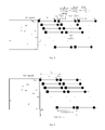
- FIG. 3 is a schematic diagram showing ERS of an APS detector nd an exposure readout mode
- FIG. 4 is a schematic diagram of an operation principle of a star sensor based on a rolling shutter mode
- FIG. 5 is a schematic diagram of a real star map of an APS star sensor and a rolling shutter imaging
- FIG. 6 is a schematic diagram of a star point prediction and extracting window (ROI) based on multiple single star attitude estimation
- FIG. 7 is a flow chart of imaging method for determining an attitude of a star sensor based on a rolling shutter imaging according to an embodiment of the present disclosure.
- a fixed star is used as a reference when the star sensor works.
- the operation principle of the star sensor is shown in FIG. 1 .
- the fixed star is imaged on a photosensitive detector via optical system of the star sensor.
- each fixed star is located in a relatively fixed position in a celestial sphere.
- the coordinate of the fixed star in the spherical coordinate system of the celestial sphere may be recorded as ( ⁇ , ⁇ ).
- a direction vector of each fixed star in the Cartesian coordinate system of the celestial sphere may be obtained as follows:
- Navigation stars may be fixed stars meeting the imaging condition of the star sensor and selected from a star catalog so as to form a navigation star catalog.
- the navigation star catalog may be stored in the star sensor, for example, a memory in the star sensor, at one time during the manufacturing process.
- a direction vector w i of the navigation star s i in the star sensor coordinate system corresponding to a direction vector v i of the navigation star s i in the celestial coordinate system may be measured through a lens of the star sensor.
- a position of a main axis center of the star sensor in a detector is (x 0 ,y 0 )
- a position coordinate of the navigation stars s i in the detector of the star sensor is (x i ,y i )
- a focal length of the star sensor is f
- A is an attitude matrix of the star sensor in the celestial coordinate system.
- the attitude matrix A of the star sensor may be directly solved by, for example, the QUEST method, that is, an optimal attitude matrix A q may be solved by minimizing a following objective function J(A q ):
- the attitude update rate of the star sensor in a tracking state is generally 4-10 Hz, which is mainly determined by the sensitivity and lens aperture of a photosensitive detector (CCD or APS CMOS), and now the photosensitive detector based on APS technology is affected by the fill factor and other factors, resulting in low sensitivity and the exposure time required to detect a specified star of usually about 100-200 ms.
- CCD photosensitive detector
- APS CMOS photosensitive detector
- the present disclosure provides a method of improving the update rate, dynamic property and precision of the star sensor significantly without increasing the mass, power consumption and volume of the star sensor.
- the exposure and readout time parameters of the star sensor are reasonably optimized, and the prediction and extraction method of the star image point is improved and the attitude determination method is innovated.
- the present disclosure may increase the attitude update rate of the star sensor by one order of magnitude, achieve high-precision and high dynamic attitude output, and completely get out of the low attitude update rate and poor dynamic property of the star sensor.
- the present disclosure may be extended to high-performance star cameras, multiple star sensor information fusion and other application systems formed by a big area or area array splicing, providing a new solution to achieve high precision, high dynamic property, high attitude update rate of the star sensor, and laying a foundation for the application of high-resolution imaging of satellites and fast response.
- the rolling shutter is the unique characteristics of the APS photosensitive detector, and the adoption of the rolling shutter mode for high-speed moving objects will present image deformation.
- the following simple example is used to illustrate the basic principle of the rolling shutter mode. An imaging of a high-speed bus in the use of the rolling shutter mode is shown in FIG. 2 .
- the exposure moments from top to bottom are different, and the time difference of the exposure start moment of each line and the exposure end moment of a previous line is t ri .
- the exposure start moment of its topmost portion is t k
- the exposure start moment of the second line is t k +t ri . Due to the forward movement of the bus in this period, a movement is generated in the image plane of the camera, causing the bus to be inclined rearward from top to bottom, which is the basic principle of distortion of the moving object resulted from the rolling shutter mode. This distortion is a perfect reflection of the object motion information during the exposure time.
- This effect provides a premise for the high update rate attitude determination of the star sensor.
- a brief description will be made by taking the bus movement in the FIG. 2 as an example. It is assumed that the position of the bus is calculated with the image, and the conventional mode is global shutter or snap shot image capturing mode. If and only if the exposure of the whole image is completed and the image results are acquired, the position of the bus is calculated. Since the entire image of the bus is exposed at the same moment, the image of the bus is not inclined, so it is unable to obtain its dynamic information and the location x 0 of the bus at the exposure moment t 0 can only be obtained.
- the locations x k -x m of the bus during t k -t m can be almost continuously obtained, if the rolling shutter mode is adopted.
- the adoption of the rolling shutter mode after the optimization design, may realize the exposure and readout at the same time, it is capable to obtain the locations of the bus at the different moments for m ⁇ k+1 times after acquiring a complete image, and the update rate is improved m ⁇ k+1 times compared with the conventional global shutter mode.
- the imaging mode based on the rolling shutter is shown in FIG. 3 .
- the rolling shutter imaging based on a line of the image sensor in the star sensor i.e. a method of performing the image processing, star map recognition and attitude operation with a unit of line, replaces the conventional frame image processing mode in which the whole image is exposed simultaneously (i.e. snap shot or global shutter), so that precise control on the exposure moment of each line of a frame of image is achieved and the exposure moments of different navigation stars are distributed sequentially.
- each star represents different attitude of the star sensor at different moments within 100 ms.
- the line exposure time is set to be identical to the total readout time, and the exposure and the readout are synchronized.
- the update rate of the star sensor is increased by 10 times, i.e. increased from the conventional 4-10 Hz to 40-100 Hz, so the dynamic property of the system will be significantly improved.
- the basic principle of the star prediction method is to perform difference recursion according to the attitude determined by the continuous two frames of star maps to estimate the attitude of the star sensor at a next moment, and to determine a location of a navigation star according to the estimated attitude.
- Specific star prediction methods are as follows.
- An initial attitude A(t 0 ) of the star sensor is obtained according to an initial capturing method.
- the movement angular velocity ⁇ tilde over ( ⁇ ) ⁇ of the star sensor generally low, for example, the angular velocity of a low earth orbit satellite is about 0.06 °/s.
- the time of ⁇ t is also about 0.1 s-0.2 s
- the predicted accuracy of a centroid is basically in the magnitude of microradian.
- Step 2 is returned to perform a next prediction and updating.
- Star sensor attitude determination based on the global exposure mode such as snap shot is to perform attitude estimation for a plurality of vector measured at the same moment, belonging to the category of deterministic algorithms, which is the basis for various attitude fusion methods.
- Conventional methods mainly comprise TRIAD, QUEST, FOAM.
- ESOQ and expansion algorithms thereof their accuracies are almost equal, and ESOO-II is the best in the computational efficiency.
- the attitude estimation based on a frame mode needs to be described briefly.
- a quaternion q generally represents an attitude
- I 3 is a 3 ⁇ 3 identity matrix, [e ⁇ ]represents a cross-product matrix defined as follows:
- 3 ⁇ 3 matrixes B and S, and 3 ⁇ 1 column vector z and proportion coefficient ⁇ are defined as follows:
- a symmetric 4 ⁇ 4 matrix K is defined as follows:
- the problem is turned into the solving of the largest eigenvalue ⁇ max of the matrix K and the corresponding eigenvector q*.
- the prerequisite of this algorithm is that measurement vectors of all star image points is at the same moment. It should be noted that, in the conventional rolling shutter mode imaging process, this condition can not be satisfied, and its accuracy is limited even if this method is used for attitude estimation.
- the method for determining the attitude of the star sensor based on the rolling shutter imaging according to an embodiment of the present disclosure will be described below with reference to FIG. 4 .
- the attitude determination method of the star sensor based on rolling shutter imaging with high dynamic property and high update rate it is capable to achieve the attitude update n times during extracting an image with n navigation stars in the star map.
- the method for determining the attitude of the star sensor based on the rolling shutter imaging may comprise steps of:
- Step S 1 will be described below in detail.
- the APS image sensor of star sensor is n lines, the line readout time of each line is t rd , and the interline integral interval time is t ri .
- t rd t ri
- the image integration (exposure) time t Int ⁇ (n ⁇ 1)t rd is capable to realize the synchronization of exposure and readout.
- this method will increase the star sensor update rate by nearly an order of magnitude.
- n is relatively large, when the star sensor is in the pipeline processing mode, it is considered that the frame processing time of the star sensor is approximately equal to the integral time of the APS image sensor.
- solid squares indicate the beginning of the exposure, and solid circle indicates the beginning of data readout.
- the embodiment according to the present disclosure for example, assuming 11 navigation stars existing in the star map of the star sensor, according to the pipeline operations rolling shutter mode, the exposure time of each navigation star is different. If taking real-time measurement information of each star image point as a reference basis for an attitude matrix update, the update rate of the attitude matrix may be increased by one order of magnitude.
- Step S 2 will be described below in detail.
- Step S 2 may comprise:
- a k represents the attitude matrix of the star sensor obtained by calculation after the location of the k th navigation star is extracted
- t k represents an exposure moment corresponding to the k th navigation star
- m k represents a line number of the k th navigation star in the image sensor
- step S 22 comprises:
- FIG. 6 represents the process of predicting the last star point of the k th image (Frame k ) from the last star point of the (k ⁇ 1) th image (Frame k ⁇ 1 ), where t Int represents the integral time of the navigation star.
- Step S 3 will be described below in detail.
- Step S 3 may comprise:
- ⁇ ⁇ ⁇ K k + 1 [ S k + 1 - ⁇ ⁇ ⁇ I 3 z k + 1 z k + 1 T ⁇ k + 1 ] ( 20 )
- step ( 32 ) a following formula is obtained according to a relation between a quaternion difference equation and the angular velocity:
- ⁇ [ ⁇ 1 , ⁇ 2 , ⁇ 3 ] a triaxial angular velocity of the star sensor.
- the k th navigation star is located in a line m k in the image
- a location of the (k+1) th navigation star located in a line m k+1 in the image is extracted
- an interval time from the k th navigation star to the (k+1) th navigation star is (m k+1 ⁇ m k )t ri , and a following formula is obtained:
- [ ⁇ ⁇ k + 1 0 ] 2 ( m k + 1 - m k ) ⁇ t ri ⁇ [ - e k + 1 q 4 , k + 1 ] ⁇ [ e k + 1 q 4 , k + 1 ] - 2 ( m k + 1 - m k ) ⁇ t ri ⁇ [ - e k + 1 q 4 , k + 1 ] ⁇ [ e k q 4 , k ] ( 25 )
- the imaging parameter optimization method of the star sensor based on the rolling shutter it is capable to achieve accurate separation of the exposure moments of different navigation stars by precisely controlling the imaging moments of different lines in the star map, which makes up for the lack of dynamic information because the exposure moments of all navigation stars in a single frame of star map are identical; and the adoption of readout and exposure pipelining work mode saves the readout time of the conventional star sensor. Therefore, a continuous navigation star prediction and extracting algorithm with high dynamic property s proposed, and a single star recursion attitude estimation method in the rolling shutter mode is also proposed, thus completing an attitude at a current moment whenever one star is extracted and breaking the algorithm constraints of the star sensor attitude determination based on the multi-vector of the frame image. Moreover, the update rate is increased by one order of magnitude compared with the conventional algorithm, and it is capable to achieve the attitude estimation while there is only one or no star in the field of view for a short time.
- the present disclosure breaks through the shortcomings such as long exposure time and long read time, poor dynamic property, deficient instantaneous view field precision and low system update rate of the conventional star sensor in the working process, thus improving the performance of the star sensor significantly.
Landscapes
- Engineering & Computer Science (AREA)
- Physics & Mathematics (AREA)
- Multimedia (AREA)
- Radar, Positioning & Navigation (AREA)
- Remote Sensing (AREA)
- Signal Processing (AREA)
- General Physics & Mathematics (AREA)
- Electromagnetism (AREA)
- Navigation (AREA)
- Computer Vision & Pattern Recognition (AREA)
- Theoretical Computer Science (AREA)
Abstract
Description
t Int≦(n−1)t rd.
ARk≡[Ak tk]=[Ak mktri]
{tilde over (ω)}1 =[I−A 1 A 0 T]/[(n−m 0 +m 1)t ri],
K k+1/k=Φk+1/k K k/kΦk+1/k T;
K k+1/k+1=(1−ρ)K k+1/k +ρδK k+1
where 0<ρ<1, and ρ represents a weighing coefficient of the kth navigation star vector; and
K k+1/k+1 q* k+1/k+1=λk+1/k+1 q* k−1/k+1
wi=Avi (3)
A p(t+δt)=[I−ωδt]A(t) (5)
{tilde over (ω)}=[I−A(t+δt)A T(t)]/(δt) (7).
A(q)=(q 4 2 −e T e)I 3+2ee T−2q 4 [e×] (8)
g(q)=q T Kq (14)
Kg*=δq* (15)
AR k ≡[A k t k ]≡[A k m k t ri] (17)
{tilde over (ω)}1 =[I−A 1 A 0 T]/[(n−m 0 +m 1)t ri] (18)
K k+1/k=Φk+1/k K k/kΦk+1/k T (19),
B k+1=αk+1 w k+1 v k+1 T
S k+1 =B k+1 +B K+1 T
z k+1=αk+1 w k+1 ×v k+1
σk+1 =tr(B k+1)
K k+1/k−1=(1−ρ)K k+/k +ρδK k+1 (21)
K k+1/k+1 q* k+1/k+1=λk+1/k+1 q* k+1/k+1 (24)
Claims (10)
t Int≦(n−1)t rd.
AR k ≡[A k t k ]=[A k m k t ri]
{tilde over (ω)}1 =[I−A 1 A 0 T]/[(n−m 0 +m 1)t ri],
K k+1/k=Φk+1/k k k/kΦk+1/k T;
K k+1/k+1=(1−ρ)K k+1/k +ρδK k+1
K k+1/k+1 q* k−1/k+1=λk+1/k+1 q* k−1/k+1
Applications Claiming Priority (4)
| Application Number | Priority Date | Filing Date | Title |
|---|---|---|---|
| CN201310053052.0 | 2013-02-18 | ||
| CN201310053052 | 2013-02-18 | ||
| CN201310053052.0A CN103148851B (en) | 2013-02-18 | 2013-02-18 | Method for determining attitude of star sensor based on roller shutter exposure imaging |
| PCT/CN2013/074743 WO2014124574A1 (en) | 2013-02-18 | 2013-04-25 | Attitude determination method for star sensor based on rolling shutter exposure imaging |
Publications (2)
| Publication Number | Publication Date |
|---|---|
| US20140232867A1 US20140232867A1 (en) | 2014-08-21 |
| US9503653B2 true US9503653B2 (en) | 2016-11-22 |
Family
ID=51350886
Family Applications (1)
| Application Number | Title | Priority Date | Filing Date |
|---|---|---|---|
| US13/983,979 Active 2034-02-08 US9503653B2 (en) | 2013-02-18 | 2013-04-25 | Method for determining attitude of star sensor based on rolling shutter imaging |
Country Status (1)
| Country | Link |
|---|---|
| US (1) | US9503653B2 (en) |
Cited By (1)
| Publication number | Priority date | Publication date | Assignee | Title |
|---|---|---|---|---|
| DE102020122748B3 (en) | 2020-08-31 | 2022-02-10 | Jena-Optronik Gesellschaft mit beschränkter Haftung | Method, device and computer program product for determining the attitude of a spacecraft in space |
Families Citing this family (21)
| Publication number | Priority date | Publication date | Assignee | Title |
|---|---|---|---|---|
| WO2015038160A1 (en) * | 2013-09-16 | 2015-03-19 | Intel Corporation | Camera and light source synchronization for object tracking |
| CA3029541A1 (en) * | 2016-06-30 | 2018-01-04 | Magic Leap, Inc. | Estimating pose in 3d space |
| CN107507123B (en) * | 2017-06-20 | 2018-10-02 | 上海航天控制技术研究所 | The quick wave door image processing system of star sensor and method |
| CN107509022B (en) * | 2017-07-21 | 2018-12-21 | 北京空间飞行器总体设计部 | A kind of with task is leading quiet rail Optical remote satellite operating mode implementation method |
| CN110702098B (en) * | 2019-10-14 | 2022-12-09 | 中国科学院新疆理化技术研究所 | Star sensor radiation damage laboratory evaluation method based on star diagonal distance measurement precision |
| CN111402300B (en) * | 2020-04-21 | 2022-09-20 | 中国科学院光电技术研究所 | A Motion Parameter Estimation Method of High Dynamic Star Sensor Based on Dual-spectral Domain Principal Component Analysis |
| CN111412915B (en) * | 2020-04-21 | 2022-08-26 | 中国科学院光电技术研究所 | Rolling shutter exposure star sensor star point position correction method based on average speed |
| CN112611372B (en) * | 2020-11-27 | 2023-11-14 | 北京理工大学 | Star sensor point light source diffraction starburst device for accurate star point position extraction |
| CN113473001B (en) * | 2021-04-07 | 2022-11-11 | 北京控制工程研究所 | Hardware-in-loop system verification system and method based on digital adjoint |
| CN114035534B (en) * | 2021-09-28 | 2023-05-09 | 北京控制工程研究所 | An electronic star-mode synchronization method suitable for very high-precision multi-probe star sensors |
| CN113932802B (en) * | 2021-10-12 | 2024-05-14 | 中国科学院微小卫星创新研究院 | Priority changing method and system for multiple star sensors |
| US12528603B2 (en) | 2021-10-26 | 2026-01-20 | Jena-Optronik Gmbh | Method, device and computer program for determining the position of a satellite using a star tracker |
| CN113970327B (en) * | 2021-11-01 | 2022-09-13 | 北京微纳星空科技有限公司 | Electronic star map simulator, electronic simulation star map generation method and electronic equipment |
| CN114279463B (en) * | 2021-12-14 | 2023-08-29 | 江苏集萃智能光电系统研究所有限公司 | Rolling shutter distortion correction method based on single-frame star map angular velocity estimation |
| CN114663492B (en) * | 2022-02-16 | 2024-02-09 | 西北工业大学 | Aircraft attitude determination method using event camera as star sensor |
| CN114812604B (en) * | 2022-03-28 | 2024-07-30 | 中国科学院微小卫星创新研究院 | Time delay correction method, system, terminal and medium for star sensor attitude determination data |
| CN114858133B (en) * | 2022-04-21 | 2023-01-17 | 武汉大学 | A low-frequency error correction method for attitude in star observation mode |
| CN114913230B (en) * | 2022-05-13 | 2024-09-20 | 哈尔滨工业大学 | A method for recognizing the attitude information of multiple types of space targets under the background of fly-by |
| CN115375695B (en) * | 2022-10-27 | 2023-03-24 | 之江实验室 | Method and device for detecting dark and weak star light spots of dynamic star sensor and medium |
| CN119289970B (en) * | 2024-10-10 | 2025-04-29 | 哈尔滨工业大学 | Star sensor time control method adopting domestic roller shutter type exposure detector |
| CN119845228B (en) * | 2024-12-02 | 2025-10-28 | 北京控制工程研究所 | A multi-mode image acquisition and processing method for visible light sensor |
Citations (10)
| Publication number | Priority date | Publication date | Assignee | Title |
|---|---|---|---|---|
| US4679753A (en) * | 1984-08-21 | 1987-07-14 | Hughes Aircraft Company | Surveying satellite incorporating star-sensing attitude determination subsystem |
| US5412574A (en) * | 1993-05-14 | 1995-05-02 | Hughes Aircraft Company | Method of attitude determination using earth and star sensors |
| US6404851B1 (en) * | 2000-03-30 | 2002-06-11 | General Electric Company | Method and apparatus for automatic exposure control using localized capacitive coupling in a matrix-addressed imaging panel |
| US20040027462A1 (en) * | 2000-09-25 | 2004-02-12 | Hing Paul Anthony | Image sensor device, apparatus and method for optical measurements |
| US20050264684A1 (en) * | 2004-05-31 | 2005-12-01 | Konica Minolta Holdings, Inc. | Image sensing apparatus |
| US20050270412A1 (en) * | 2004-06-04 | 2005-12-08 | Konica Minolta Holdings, Inc. | Image sensing apparatus |
| US20060085130A1 (en) * | 2004-10-18 | 2006-04-20 | Trex Enterprises Corporation | Daytime stellar imager for attitude determination |
| US20060238632A1 (en) * | 2005-04-26 | 2006-10-26 | Micron Technology, Inc. | Rolling shutter for prevention of blooming |
| US20110010129A1 (en) * | 2009-07-09 | 2011-01-13 | Richard Kirby | Positioning system and method using optically tracked anchor points |
| US20110019022A1 (en) * | 2008-01-09 | 2011-01-27 | European Space Agency | Active pixel sensor apparatus for use in a star tracker device |
-
2013
- 2013-04-25 US US13/983,979 patent/US9503653B2/en active Active
Patent Citations (10)
| Publication number | Priority date | Publication date | Assignee | Title |
|---|---|---|---|---|
| US4679753A (en) * | 1984-08-21 | 1987-07-14 | Hughes Aircraft Company | Surveying satellite incorporating star-sensing attitude determination subsystem |
| US5412574A (en) * | 1993-05-14 | 1995-05-02 | Hughes Aircraft Company | Method of attitude determination using earth and star sensors |
| US6404851B1 (en) * | 2000-03-30 | 2002-06-11 | General Electric Company | Method and apparatus for automatic exposure control using localized capacitive coupling in a matrix-addressed imaging panel |
| US20040027462A1 (en) * | 2000-09-25 | 2004-02-12 | Hing Paul Anthony | Image sensor device, apparatus and method for optical measurements |
| US20050264684A1 (en) * | 2004-05-31 | 2005-12-01 | Konica Minolta Holdings, Inc. | Image sensing apparatus |
| US20050270412A1 (en) * | 2004-06-04 | 2005-12-08 | Konica Minolta Holdings, Inc. | Image sensing apparatus |
| US20060085130A1 (en) * | 2004-10-18 | 2006-04-20 | Trex Enterprises Corporation | Daytime stellar imager for attitude determination |
| US20060238632A1 (en) * | 2005-04-26 | 2006-10-26 | Micron Technology, Inc. | Rolling shutter for prevention of blooming |
| US20110019022A1 (en) * | 2008-01-09 | 2011-01-27 | European Space Agency | Active pixel sensor apparatus for use in a star tracker device |
| US20110010129A1 (en) * | 2009-07-09 | 2011-01-13 | Richard Kirby | Positioning system and method using optically tracked anchor points |
Cited By (2)
| Publication number | Priority date | Publication date | Assignee | Title |
|---|---|---|---|---|
| DE102020122748B3 (en) | 2020-08-31 | 2022-02-10 | Jena-Optronik Gesellschaft mit beschränkter Haftung | Method, device and computer program product for determining the attitude of a spacecraft in space |
| WO2022043247A1 (en) | 2020-08-31 | 2022-03-03 | Jena-Optronik Gmbh | Method, device and computer program product for determining the position of a spacecraft in space |
Also Published As
| Publication number | Publication date |
|---|---|
| US20140232867A1 (en) | 2014-08-21 |
Similar Documents
| Publication | Publication Date | Title |
|---|---|---|
| US9503653B2 (en) | Method for determining attitude of star sensor based on rolling shutter imaging | |
| CN103148851B (en) | Method for determining attitude of star sensor based on roller shutter exposure imaging | |
| CN111024066B (en) | A vision-inertial fusion indoor positioning method for drones | |
| CN109540126B (en) | Inertial vision integrated navigation method based on optical flow method | |
| CN113436261B (en) | Monocular vision inertial positioning method for automatic driving of closed park | |
| CN103033189B (en) | Inertia/vision integrated navigation method for deep-space detection patrolling device | |
| CN101344391B (en) | Lunar vehicle posture self-confirming method based on full-function sun-compass | |
| CN111156998A (en) | A Mobile Robot Localization Method Based on RGB-D Camera and IMU Information Fusion | |
| CN107560603B (en) | Unmanned aerial vehicle oblique photography measurement system and measurement method | |
| CN106441151A (en) | Measuring system for three-dimensional target Euclidean space reconstruction based on vision and active optical fusion | |
| CN112461210A (en) | Air-ground cooperative building surveying and mapping robot system and surveying and mapping method thereof | |
| CN105469405A (en) | Visual ranging-based simultaneous localization and map construction method | |
| CN107478220A (en) | Unmanned plane indoor navigation method, device, unmanned plane and storage medium | |
| KR20120099952A (en) | Sensor system, and system and method for preparing environment map using the same | |
| CN116007609A (en) | Positioning method and computing system for fusion of multispectral image and inertial navigation | |
| KR20200056613A (en) | System for correcting geometry of mobile platform with sensor based on an orthophoto | |
| CN118967795B (en) | Visual inertial navigation tight coupling SLAM method based on four-eye panoramic camera | |
| Ramezani et al. | Pose estimation by omnidirectional visual-inertial odometry | |
| CN104567801B (en) | High-precision laser measuring method based on stereoscopic vision | |
| CN116027351B (en) | A handheld/backpack SLAM device and positioning method | |
| CN114114311B (en) | A relative pose measurement method for non-cooperative spacecraft based on multi-source information fusion | |
| CN111247389A (en) | Data processing method, device and image processing device for photographing equipment | |
| Ramezani et al. | Omnidirectional visual-inertial odometry using multi-state constraint Kalman filter | |
| CN114723811A (en) | Stereo vision positioning and mapping method for quadruped robot in unstructured environment | |
| CN121353426A (en) | A Three-Axis Gimbal Target Positioning Method and System Based on DEM Files |
Legal Events
| Date | Code | Title | Description |
|---|---|---|---|
| AS | Assignment |
Owner name: TSINGHUA UNIVERSITY, CHINA Free format text: ASSIGNMENT OF ASSIGNORS INTEREST;ASSIGNORS:XING, FEI;YOU, ZHENG;SUN, TING;REEL/FRAME:030953/0069 Effective date: 20130731 |
|
| STCF | Information on status: patent grant |
Free format text: PATENTED CASE |
|
| MAFP | Maintenance fee payment |
Free format text: PAYMENT OF MAINTENANCE FEE, 4TH YR, SMALL ENTITY (ORIGINAL EVENT CODE: M2551); ENTITY STATUS OF PATENT OWNER: SMALL ENTITY Year of fee payment: 4 |
|
| MAFP | Maintenance fee payment |
Free format text: PAYMENT OF MAINTENANCE FEE, 8TH YR, SMALL ENTITY (ORIGINAL EVENT CODE: M2552); ENTITY STATUS OF PATENT OWNER: SMALL ENTITY Year of fee payment: 8 |