US9503603B2 - Reading apparatus, correction value calculating method and ink jet recording apparatus - Google Patents
Reading apparatus, correction value calculating method and ink jet recording apparatus Download PDFInfo
- Publication number
- US9503603B2 US9503603B2 US15/067,229 US201615067229A US9503603B2 US 9503603 B2 US9503603 B2 US 9503603B2 US 201615067229 A US201615067229 A US 201615067229A US 9503603 B2 US9503603 B2 US 9503603B2
- Authority
- US
- United States
- Prior art keywords
- reading
- values
- pixels
- correction value
- correction
- Prior art date
- Legal status (The legal status is an assumption and is not a legal conclusion. Google has not performed a legal analysis and makes no representation as to the accuracy of the status listed.)
- Expired - Fee Related
Links
- 238000012937 correction Methods 0.000 title claims abstract description 168
- 238000000034 method Methods 0.000 title claims abstract description 65
- 238000003705 background correction Methods 0.000 claims abstract description 153
- 230000002123 temporal effect Effects 0.000 claims description 73
- 238000012545 processing Methods 0.000 claims description 11
- 238000003860 storage Methods 0.000 claims description 7
- 230000035945 sensitivity Effects 0.000 description 31
- 238000010586 diagram Methods 0.000 description 28
- 238000005286 illumination Methods 0.000 description 15
- 238000011109 contamination Methods 0.000 description 10
- 238000011156 evaluation Methods 0.000 description 9
- 230000002159 abnormal effect Effects 0.000 description 8
- 238000004364 calculation method Methods 0.000 description 7
- 238000009826 distribution Methods 0.000 description 7
- 238000012935 Averaging Methods 0.000 description 5
- 230000008569 process Effects 0.000 description 5
- 230000003287 optical effect Effects 0.000 description 4
- 230000007547 defect Effects 0.000 description 3
- 238000004422 calculation algorithm Methods 0.000 description 2
- 230000015556 catabolic process Effects 0.000 description 2
- 230000008859 change Effects 0.000 description 2
- 238000006731 degradation reaction Methods 0.000 description 2
- 230000001747 exhibiting effect Effects 0.000 description 2
- 238000004519 manufacturing process Methods 0.000 description 2
- 230000003595 spectral effect Effects 0.000 description 2
- 230000004075 alteration Effects 0.000 description 1
- 238000003491 array Methods 0.000 description 1
- 239000003086 colorant Substances 0.000 description 1
- 238000001514 detection method Methods 0.000 description 1
- 238000007599 discharging Methods 0.000 description 1
- 230000000694 effects Effects 0.000 description 1
- 230000006870 function Effects 0.000 description 1
- 230000006872 improvement Effects 0.000 description 1
- 238000005457 optimization Methods 0.000 description 1
- 238000011144 upstream manufacturing Methods 0.000 description 1
Images


Classifications
-
- H—ELECTRICITY
- H04—ELECTRIC COMMUNICATION TECHNIQUE
- H04N—PICTORIAL COMMUNICATION, e.g. TELEVISION
- H04N1/00—Scanning, transmission or reproduction of documents or the like, e.g. facsimile transmission; Details thereof
- H04N1/024—Details of scanning heads ; Means for illuminating the original
- H04N1/02418—Details of scanning heads ; Means for illuminating the original for picture information pick up and reproduction
-
- H—ELECTRICITY
- H04—ELECTRIC COMMUNICATION TECHNIQUE
- H04N—PICTORIAL COMMUNICATION, e.g. TELEVISION
- H04N1/00—Scanning, transmission or reproduction of documents or the like, e.g. facsimile transmission; Details thereof
- H04N1/00795—Reading arrangements
- H04N1/00798—Circuits or arrangements for the control thereof, e.g. using a programmed control device or according to a measured quantity
-
- H—ELECTRICITY
- H04—ELECTRIC COMMUNICATION TECHNIQUE
- H04N—PICTORIAL COMMUNICATION, e.g. TELEVISION
- H04N1/00—Scanning, transmission or reproduction of documents or the like, e.g. facsimile transmission; Details thereof
- H04N1/024—Details of scanning heads ; Means for illuminating the original
- H04N1/032—Details of scanning heads ; Means for illuminating the original for picture information reproduction
- H04N1/034—Details of scanning heads ; Means for illuminating the original for picture information reproduction using ink, e.g. ink-jet heads
-
- H—ELECTRICITY
- H04—ELECTRIC COMMUNICATION TECHNIQUE
- H04N—PICTORIAL COMMUNICATION, e.g. TELEVISION
- H04N1/00—Scanning, transmission or reproduction of documents or the like, e.g. facsimile transmission; Details thereof
- H04N1/21—Intermediate information storage
-
- H—ELECTRICITY
- H04—ELECTRIC COMMUNICATION TECHNIQUE
- H04N—PICTORIAL COMMUNICATION, e.g. TELEVISION
- H04N2201/00—Indexing scheme relating to scanning, transmission or reproduction of documents or the like, and to details thereof
- H04N2201/0077—Types of the still picture apparatus
- H04N2201/0081—Image reader
Definitions
- the present invention relates to a reading apparatus, a correction value calculating method and an ink jet recording apparatus, and, more particularly, to a technique for calculating a shading correction value of an image pickup element from a result of a reference plate being read by the image pickup element.
- Japanese Patent Application Laid-Open No. 2003-219124 discloses moving a reference plane of a reference plate in a direction different from a conveyance direction of a document sheet, and correcting reading sensitivity based on an average value or a maximum value of a plurality of pieces of image data respectively read from the moved reference plane.
- Japanese Patent Application Laid-Open No. 2003-219124 if a detection position of abnormal data is moved in accordance with movement of the reference plane, it is determined that the abnormal data is caused by contamination, or the like, on the reference plane.
- a desirable value (normal value) of the image data is required to be a large value (the large value indicates “bright”).
- Japanese Patent Application Laid-Open No. 2003-219124 describes that the value of the image data is small in a portion of contamination of the reference plate, there is a case where when the reference plane has a flaw, a flaw portion reflects more light depending on a cross-section shape of the flaw and makes the image data larger than that in the case where there is no flaw. Therefore, in such a case, if the maximum value among the pieces of the image data is used, it is impossible to exclude an abnormal value.
- Japanese Patent Application Laid-Open No. 2003-219124 describes that it is determined whether a piece of image data exhibiting an abnormal value included in reference data is caused by contamination of the reference plane or performance degradation of an element, a determining method is not specifically disclosed.
- Japanese Patent Application Laid-Open No. 2003-219124 describes influence by contamination on only a pixel of an abnormal value and pixels adjacent to the pixel of the abnormal value, the contamination may affect reading values of pixels in a broader range according to a size and distribution of density of the contamination and reading resolution, and a degree of the influence may be great in some pixels and small in other pixels.
- a correction state becomes discontinuous at a border between a pixel equal to or greater than the threshold and a pixel less than the threshold, which may cause a defect such as a stripe in the corrected image.
- the technique disclosed in Japanese Patent Application Laid-Open No. 2003-219124 includes a problem that it is impossible to acquire a shading correction value while appropriately excluding influence of contamination, or the like, on the reference plane.
- the present invention has been made in view of the above-described circumstances, and an object of the present invention is to provide a reading apparatus which can appropriately calculate a shading correction value even when there is ununiformity in density of a reference member which becomes a reference for shading correction, a correction value calculation method and an ink jet recording apparatus.
- the correction value calculating method includes a reading value acquiring step of acquiring reading values at respective pixels for respective reading positions at both ends of a reading range of a reference member and reading values at respective two or more pixels for respective reading positions in the reading range except the reading positions, and reading values for respective two or more reading positions at the respective pixels while relatively moving the image pickup element and the reference member which becomes a reference for shading correction in the first direction, and a correction value calculating step of calculating the correction value for shading correction based on the acquired reading values.
- the image pickup element and the reference member which becomes a reference for shading correction are relatively moved in the first direction, the reading values at respective pixels for respective reading positions at both ends of the reading range of the reference member and the reading values at respective two or more pixels for respective reading positions in the reading range except the reading positions, and the reading values for respective two or more reading positions at the respective pixels are acquired, and the correction value for shading correction is calculated based on the acquired reading values, even if there is ununiformity in density of the reference member which becomes a reference for shading correction, it is possible to appropriately calculate a correction value for shading correction.
- the correction value calculating method further includes a reading value variation acquiring step of acquiring variation of the reading values of the respective pixels by solving a system of equations in which the variation of the reading values of the respective pixels based on the acquired reading values and variation of density of the respective reading positions are set at unknowns, and in the correction value calculating step, the correction value for shading correction is calculated based on the variation of the reading values of the respective pixels.
- variation of the reading values of the respective pixels which averagely satisfies a system of equations in which noise included in the acquired reading values is set at an unknown is acquired using a Newton's method, a bisection method or a least-square method.
- a correction value for shading correction is calculated by performing repeat operation based on the acquired reading values. By this means, it is possible to appropriately calculate a correction value for shading correction.
- the correction value calculating step includes a temporal correction value calculating step of calculating temporal correction values of the respective pixels based on an average value of the reading values for two or more reading positions at the respective pixels, a reflectance error calculating step of calculating reflectance errors of the respective positions based on an average value of results obtained by performing temporal correction on the reading values for respective positions of the reference member using the temporal correction values, a converting step of converting the reading values for the two or more reading positions at the respective pixels into new reading values using the reflectance errors, and an operation controlling step of causing repeat operation of processing in the temporal correction value calculating step, the reflectance error calculating step and the converting step to be performed, and setting a temporal correction value finally calculated through the repeat operation as the correction value for shading correction.
- a temporal correction value calculating step of calculating temporal correction values of the respective pixels based on an average value of the reading values for two or more reading positions at the respective pixels
- a reflectance error calculating step of calculating reflectance errors of the respective positions based
- the correction value calculating method further includes a determining step of determining whether or not the temporal correction values converge, and in the operation controlling step, the repeat operation is caused to be performed until it is determined that the temporal correction values converge.
- the repeat operation is caused to be performed until it is determined that the temporal correction values converge.
- the correction value calculating method further includes a counting step of counting the number of repetitions of the repeat operation, and in the operation controlling step, the repeat operation is caused to be performed until the number of repetitions becomes equal to or greater than a threshold. By this means, it is possible to appropriately perform the repeat operation.
- a reading apparatus includes a reference member which becomes a reference for shading correction, an image pickup element in which a plurality of pixels are arranged along at least a first direction, a shading correction device configured to correct variation of reading values of the plurality of pixels using a correction value for shading correction, a moving device configured to relatively move the reference member and the image pickup element in the first direction, a reading value acquiring device configured to cause the image pickup element to read the reference member, and acquire reading values at respective pixels for respective reading positions at both ends in a reading range of the reference member and reading values at respective two or more pixels for respective reading positions in the reading range except the reading positions, and reading values for respective two or more reading positions at the respective pixels, and a correction value calculating device configured to calculate a correction value for shading correction based on the acquired reading values.
- the image pickup element and the reference member which becomes a reference for shading correction are relatively moved in the first direction, the reading values at respective pixels for respective reading positions at both ends of the reading range of the reference member and the reading values at respective two or more pixels for respective reading positions in the reading range except the reading positions, and the reading values for respective two or more reading positions at the respective pixels are acquired, and the correction value for shading correction is calculated based on the acquired reading values, it is possible to appropriately calculate a correction value for shading correction even if there is ununiformity in density of the reference member which becomes a reference for shading correction.
- the moving device relatively moves the reference member and the image pickup element along the first direction or the second direction.
- the reading apparatus includes a light source configured to illuminate the reference member with light.
- a light source configured to illuminate the reference member with light.
- the reading apparatus includes a storage device configured to store a correction value for shading correction. It is possible to perform shading correction of the image pickup element by reading out the correction value for shading correction from the storage device.
- an ink jet recording apparatus includes an ink jet head and a reading apparatus configured to read an image recorded by the ink jet head, the reading apparatus including a reference member which becomes a reference for shading correction, an image pickup element in which a plurality of pixels are arranged along at least a first direction, a shading correction device which corrects variation of reading values of the plurality of pixels using a correction value for shading correction, a moving device which relatively moves the reference member and the image pickup element in the first direction, a reading value acquiring device which causes the image pickup element to read the reference member and acquires reading values at respective pixels for respective reading positions at both ends of a reading range of the reference member and reading values at respective two or more pixels for respective reading positions in the reading range except the reading positions, and reading values for respective two or more reading positions at the respective pixels, and a correction value calculating device which calculates a correction value for shading correction based on the acquired reading values.
- the image pickup element and the reference member which becomes a reference for shading correction are relatively moved in the first direction, the reading values at respective pixels for respective reading positions at both ends of the reading range of the reference member and the reading values at respective two or more pixels for respective reading positions in the reading range except the reading positions, and the reading values for respective two or more reading positions at the respective pixels are acquired, and the correction value for shading correction is calculated based on the acquired reading values, it is possible to appropriately calculate a shading correction value even when there is ununiformity in density of the reference member which becomes a reference for shading correction.
- a non-transitory tangible computer-readable recording medium including instructions stored thereon, such that when the instructions are read and executed by a computer, the computer is configured to perform a correction value calculating method of a reading apparatus which includes an image pickup element in which a plurality of pixels are arranged along a first direction, and a shading correction device configured to correct variation of reading values of the plurality of pixels using a correction value for shading correction, the correction value calculating method including a reading value acquiring step of acquiring reading values at respective pixels for respective reading positions at both ends of a reading range of a reference member and reading values at respective two or more pixels for respective reading positions in the reading range except the reading positions, and reading values for respective two or more reading positions at the respective pixels while relatively moving the image pickup element and the reference member which becomes a reference for shading correction in the first direction, and a correction value calculating step of calculating the correction value for shading correction based on the acquired reading values.
- the image pickup element and the reference member which becomes a reference for shading correction are relatively moved in the first direction, the reading values at respective pixels for respective reading positions at both ends of the reading range of the reference member and the reading values at respective two or more pixels for respective reading position in the reading range except the reading positions, and the reading values for respective two or more reading positions at the respective pixels are acquired, and the correction value for shading correction is calculated based on the acquired reading values, it is possible to appropriately calculate a shading correction value even if there is ununiformity in density of the reference member which becomes a reference for shading correction.
- FIG. 1 is an overall configuration diagram of a reading apparatus 10 ;
- FIG. 2 is a diagram illustrating a reading face of a line sensor 20 ;
- FIG. 3 is a diagram illustrating reading operation of a white reference plate 40 ;
- FIG. 4 is a diagram illustrating a reference plane 40 a of the white reference plate 40 :
- FIG. 5 is a diagram illustrating relationship of respective pixels PX i of the line sensor 20 at respective reading time and reading positions on the reference plane 40 a of the white reference plate 40 ;
- FIG. 6 is a diagram illustrating acquired data of the respective pixels PX i of the line sensor 20 at the respective reading time
- FIG. 7 is a diagram illustrating reflectance of respective reading positions LC j on the reference plane 40 a;
- FIGS. 8A and 8B are diagrams illustrating “target values”, “overall sensitivity” and “ideal correction coefficients” of the respective pixels PX i :
- FIG. 9 is a flowchart illustrating a shading correction value calculating method according to a second embodiment:
- FIG. 10 is a diagram illustrating overall sensitivity of the respective pixels PX i while time elapses
- FIG. 1 is a diagram illustrating reflectance of the respective reading positions LC j read by the respective pixels PX i at respective reading time T k ;
- FIG. 12 is a diagram illustrating reading values read at the respective positions LC j by the respective pixels PX i at the respective reading time T k , average values of the reading values and temporal correction coefficients of the respective pixels PX i :
- FIG. 13 is a diagram illustrating a result obtained by correcting the reading values read at the respective positions LC j using a temporal shading correction value
- FIG. 14 is a diagram illustrating ratios of reflectance at the respective reading positions LC j ;
- FIG. 15 is a diagram illustrating calculated new reading values of the respective pixels PX i ;
- FIG. 16 is a diagram illustrating a result obtained by correcting the reading values read at the respective positions LC j using the temporal shading correction value:
- FIG. 17 is a diagram illustrating ratios of reflectance at the respective reading positions LC j ;
- FIG. 18 is a diagram illustrating calculated new reading values of the respective pixels PX i ;
- FIG. 19 is a diagram illustrating a result obtained by correcting the reading values read at the respective positions LC j using the temporal shading correction value
- FIG. 20 is a diagram illustrating ratios of reflectance of the respective reading positions LC j ;
- FIG. 21 is a diagram illustrating calculated new reading values of the respective pixels PX i ;
- FIG. 22 is a diagram illustrating a result obtained by correcting the reading values read at the respective positions LC j using the temporal shading correction value
- FIG. 23 is a diagram illustrating ratios of reflectance at the respective reading positions LC j ;
- FIG. 24 is a diagram illustrating calculated new reading values of the respective pixels PX i ;
- FIG. 25 is a diagram illustrating a result obtained by correcting the reading values read at the respective positions LC j using the temporal shading correction value:
- FIG. 26 is a diagram illustrating ratios of reflectance at the respective reading positions LC j ;
- FIG. 27 is a diagram illustrating calculated new reading values of the respective pixels PX i ;
- FIG. 28 is a block diagram illustrating an electrical configuration of the reading apparatus 10 ;
- FIG. 29 is a block diagram of a shading correction value acquiring unit.
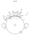
- FIG. 30 is a schematic side view illustrating an ink jet recording apparatus.
- a reading apparatus 10 is an apparatus which reads an image recorded on a recording face of conveyed paper 1 and converts the image into image data, and, as illustrated in FIG. 1 , includes a line sensor 20 , a lens 30 , a white reference plate 40 , or the like.
- the paper 1 is a sheet type recording medium.
- the paper 1 is conveyed in a conveyance direction (Y direction in the figure) by a conveying unit 50 (not illustrated in FIG. 1 , see FIG. 28 ) while the recording face on which the image is recorded faces upward in a vertical direction (Z direction in the figure).
- the line sensor 20 is provided above in a vertical direction on a conveyance path of the paper 1 .
- the line sensor 20 is a monochromatic one-dimensional line sensor.
- an image pickup element 22 is provided on a reading face 20 a of the line sensor 20 .
- the line sensor 20 is a monochromatic one-dimensional line sensor in the present embodiment, it is also possible to apply an aspect where the line sensor 20 is a one-dimensional line sensor in which two or more pixel arrays having different spectral sensitivity are integrally formed, such as a color line sensor including R, G. B color filters. Further, it is also possible to apply an aspect where a two-dimensional plane sensor is used in place of the one-dimensional line sensor. Still further, while the image pickup element 22 has 17 pixels PX i , the present embodiment can be applied if the number of pixels is two or more.
- the lens 30 is provided between the conveyance path of the paper 1 and the line sensor 20 .
- the lens 30 makes the image pickup element 22 form an image of a fixed range (image pickup range) on the recording face of the paper 1 while focusing on the recording face of the paper 1 .
- the reading apparatus 10 includes illumination 60 (not illustrated in FIG. 1 , see FIG. 28 , one example ds of a light source) which illuminates at least the image pickup range on the paper 1 by the line sensor 20 with light.
- the illumination 60 is fixed with respect to the line sensor 20 .
- the white reference plate 40 which is a reference member which becomes a reference for shading correction of the image pickup element 22 , includes a reference plane 40 a so that the image pickup element 22 acquires white reference data. While the reference plane 40 a is a white face with uniform density (reflectance) in the present embodiment, it is also possible to apply an aspect where a gray reference plane 40 a is used.
- the reading apparatus 10 evacuates the white reference plate 40 to an evacuation position where the white reference plate 40 does not interfere with conveyance of the paper 1 by a driving unit 70 (not illustrated in FIG. 1 , see FIG. 28 ) when the line sensor 20 reads the paper 1 .
- the conveying unit 50 conveys the paper 1 in a conveyance direction, and the illumination 60 illuminates the image pickup range on the recording face of the paper 1 by the line sensor 20 .
- the lens 30 makes the image pickup element 22 form an image of the image pickup range on the recording face of the paper 1 .
- the line sensor 20 reads the formed image on the recording face of the paper 1 using the image pickup element 22 and outputs read data.
- the reading apparatus 10 makes the driving unit 70 move the white reference plate 40 from the evacuation position to a position included in the image pickup range by the line sensor 20 .
- This state corresponds to a state where a bright image like a white image is read or a state where an intermediate gray image is read. Therefore, reading values on the reference plane 40 a outputted from the respective pixels PX i of the image pickup element 22 become positive values which are not 0 (jet black state).
- the white reference plate 40 is located in the image pickup range by the line sensor 20 , the respective pixels PX i of the image pickup element 22 correspond to any position of the respective reading positions LC j . It should be noted that because the number of pixels of the image pickup element 22 is smaller than the number of reading positions LC j , there are reading positions LC j that pixels PX i of specific numbers do not correspond to.
- FIG. 4 illustrates the reading positions LC j with round shapes, this is intended to make it easier to distinguish in the illustration, the accurate shapes of the reading positions are determined by the shapes of the pixels PX i of the image pickup element, aberration property of a lens to be used, flare, ghost property and a focusing state.
- the driving unit 70 (one example of the moving device) is configured so that the white reference plate 40 can move by one reading each in an arrangement direction (X direction in the figure) of the pixels of the image pickup element 22 in this state. It should be noted that it is only necessary that the driving unit 70 can relatively move the line sensor 20 and the white reference plate 40 . Therefore, the driving unit 70 is not limited to one which moves the white reference plate 40 , but may be one which moves the line sensor 20 or one which moves both the line sensor 20 and the white reference plate 40 . Further, the movement is not limited to movement by one reading position each, but may be movement by a plurality of reading positions each.
- the reading apparatus 10 makes the driving unit 70 move the white reference plate 40 by one reading position each in an X direction for each reading time. That is, the driving unit 70 moves the white reference plate 40 so that the reading positions LC j of the reference plane 40 a are sequentially read by different pixels PX i of the image pickup element 22 for each reading time.
- the line sensor 20 acquires reading values of the reading positions LC j respectively facing the line sensor 20 in the respective pixels PX i by sequentially reading the moving white reference plate 40 for each reading time.
- a pixel PX 1 reads a reading position LC 1
- a pixel PX 2 reads a reading position LC 2
- a pixel PX 3 reads a reading position LC 3
- a pixel PX 17 reads a reading position LC 17
- the white reference plate 40 is relatively moved by one reading position in the X direction
- the pixel PX 1 reads the reading position LC 2
- the pixel PX 2 reads the reading position LC 3
- the pixel PX 3 reads the reading position LC 4
- . . . , the pixel PX 17 reads a reading position LC 18 .
- the pixel PX i reads different reading positions LC 1 , LC 2 , LC 3 . . . . , LC 10 on the reference plane 40 a as the reading time elapses from T 1 to T 10 .
- the reading position LC 17 is read by different pixels PX 17 , PX 16 , PX 15 , . . . , PX 8 as the reading time elapses from T 1 to T 10 .
- the reading apparatus 10 causes the reading positions LC 1 , LC 26 at both ends of a reading range 40 b on the reference plane 40 a to be read by respective pixels PX 1 , PX 17 , causes the reading positions LC 2 to LC 25 of the reading range 40 b except the reading positions LC 1 , LC 26 to be read by respective two or more pixels PX i , and causes the two or more reading positions LC j on the reference plane 40 a to be read by respective pixels PX i .
- the line sensor 20 reads a finite range
- a reading position for example, reading position LC 1
- a reading position which is close to an end of the reference plane 40 a of the white reference plate 40 in the X direction
- this causes no problem.
- a reading position for example, reading position LC 26
- LC 26 which is outside the initial image pickup range by the line sensor 20 before the white reference plate 40 moves in the X direction
- this also causes no problem.
- reading values of the reading positions LC j read by the respective pixels PX i of the image pickup element 22 are set at D(i, j). That is, as illustrated in FIG. 6 , a reading value of the reading position LC 1 read by the pixel PX 1 is D(1,1), a reading value of the reading position LC 2 read by the pixel PX 2 is D(2,2), . . . , a reading value of the reading position LC 25 read by the pixel PX 16 is D(16, 25), and a reading value of the reading position LC 26 read by the pixel PX 17 is D(17, 26).
- the reading values D(1, j), D(2,j), D(3,j), . . . at the same reading positions LC j on the reference plane 40 a become the same value, and this value corresponds to density of the reading positions LC j of the white reference plate 40 .
- the reading values D(i,1), D(i,2), D(i,3), . . . by the same pixels PX i become the same value.
- the illumination 60 is fixed with respect to the line sensor 20 here, when there is distribution of the light amount of the illumination 60 , the distribution of the light amount of the illumination 60 is included in the variation of optical property of the pixels PX i . Meanwhile, when the illumination 60 moves together with the white reference plate 40 , the distribution of the light amount of the illumination 60 is included in the variation of the density of the reading positions LC j .
- a method for calculating a shading correction value (one example of a correction value for shading correction) to correct variation of the reading values of the respective pixels of the above-described image pickup element (one example of a correction value calculating method of the reading apparatus) will be described.
- the image pickup element 22 and the white reference plate 40 are relatively moved in the X direction using the above-described reading method of the white reference plate, and reading values at respective pixels PX 1 , PX 17 for the reading positions LC 1 , LC 26 at both ends of the reading range 40 b and reading values at respective two or more pixels PX i for the reading positions LC 2 to LC 25 in the reading range 40 b except the reading positions LC 1 , LC 26 , and reading values for respective two or more reading positions LC j at the respective pixels PX i are acquired (one example of a reading value acquiring step), a system of equations is written in which reading variation of the respective pixels PX i of the image pickup element 22 and density variation of the respective reading positions LC
- the reading variation of the respective pixels PX i is variation of the reading values of the respective pixels PX i for fixed density, and is indicated with a ratio of the reading values of the respective pixels PX i and a reference reading value here.
- the density variation of the respective reading positions LC j is a ratio of density of the respective reading positions LC j and reference density.
- the number of equations in the system of equations is a product (a ⁇ b) of the number of pixels which perform reading (a) and the number of times of reading performed at the respective pixels (the number of times of reading, b) while the line sensor 20 and the white reference plate 40 are relatively moved.
- the number of pixels is 17 of the pixel PX i to the pixel PX 17
- the number of times of reading performed at the 17 pixels while the line sensor 20 and the white reference plate 40 are relatively moved is 10 at reading time T 1 to reading time T 10
- the reading variation of the respective pixels PX i is equal to the number of pixels (a)
- the density variation of the respective reading positions LC j is equal to the number of reading positions (a+b ⁇ 1) at which reading is performed.
- equation 2 (equation 2)
- equation 2 when a is 1, a left side becomes 0, and a right side becomes 1, and equation 2 is not true.
- equation 2 A further variation of equation 2 in the case where a is an integer equal to or greater than 2 can be expressed as: b ⁇ (2 ⁇ a ⁇ 1) ⁇ ( a ⁇ 1) (equation 3).
- b is set at 2
- a solution is indeterminate and underspecified, because in the present embodiment, it is directed to calculating a shading correction value, by adding requirements that an average value of solutions is a predetermined value, a solution can be specified.
- the shading correction value is a ratio which corrects a reading value to a target value
- the predetermined value may be set at, for example, 1.
- the number of equations is considerably larger than the number of unknowns, it is possible to solve the system of equations.
- the reading values by the respective pixels PX i include noise, to be precise, this noise value becomes an unknown.
- this value is equal to the number of equations in the system of equations, the number of unknowns becomes necessarily larger than the number of equations, which makes it impossible to solve the system of equations. In this case, it is only necessary to find a solution which averagely satisfies the system of equations by increasing the number of equations by securing a larger number of times of reading and using a Newton's method, a bisection method or a least-square method.
- a shading correction value for correcting the reading variation of the respective pixels PX i may be set at a value proportional to an inverse of the reading variation of the respective pixels PX i .
- a shading correction value calculating method (one example of the correction value calculating method of the reading apparatus) which is simpler in numerical calculation than that in the first embodiment, but which can obtain a correction value (one example of a correction value for shading correction) with sufficient accuracy and which takes into account characteristics of reading at the line sensor, such as a state where a solution can be found that reading values of the same pixels of the line sensor become substantially the same.
- reflectance of the reference plane 40 a and overall sensitivity of the respective pixels PX i of the image pickup element 22 will be defined in advance.
- FIG. 7 illustrates values of reflectance [unit: %] of the respective reading positions LC j on the reference plane 40 a defined in advance, and the values are dealt as “true reflectance” in the second embodiment. While values of the true reflectance in an actual apparatus are unknown values which are determined according to manufacturing variation, contamination, or the like, of the white reference plate 40 , here, the values of the true reflectance are randomly determined within a range of variation determined in advance. The range of variation of the reflectance is 5.00 [% P ⁇ P] which is indicated as “reflectance unevenness set value [% P ⁇ P]” in FIG. 7 .
- [% P ⁇ P] indicates a difference between maximum possible reflectance [%] and minimum possible reflectance [%] among the reflectance of the respective reading positions LC j . (Actually, whether the reflectance becomes maximum or minimum is randomly determined, maximum and minimum reflectance values do not necessarily exist.)
- the reflectance illustrated in FIG. 7 is determined using average reflectance of 100 [%], the reflectance includes a value greater than 100 [%]. Further, here, because the number of reading positions LC j is small, the average reflectance is not 100 [%] due to influence of random variation. In the second embodiment, it is possible to appropriately obtain a correction coefficient including this gap of the average reflectance. It should be noted that it is not necessary that the average reflectance is 100 [%], and it is also possible to use actual arbitrary reflectance on the reference plane 40 a other than 0 [%].
- FIG. 8A illustrates a “target value” of the reading values of the respective pixels PX i of the image pickup element 22 .
- This target value is a value of a result obtained by performing variation correction using a shading correction value on the reading values of the respective pixels PX i for the reference plane 40 a . That is, after the variation correction, the reading values on the reference plane 40 a become the target value in all the pixels PX i .
- This target value can be determined to be an arbitrary value.
- the target value may be determined to be 200.
- FIG. 8B illustrates values of “overall sensitivity” and “ideal correction coefficients” of the respective pixels PX i defined in advance.
- the “overall sensitivity” of the respective pixels PX i is unknown values determined according to sensitivity variation of the respective pixels PX i and variation of distribution of the light amount of the illumination in an actual apparatus, and can be expressed with a product of sensitivity of the respective pixels PX i and distribution of the light amount of the illumination.
- the overall sensitivity is randomly determined within a range of variation determined in advance.
- the range of variation of the overall sensitivity is 0.4 [P ⁇ P] which is indicated as “sensitivity variation set value [P ⁇ P]” in FIG. 8B .
- [P ⁇ P] indicates a difference between maximum possible overall sensitivity and minimum possible overall sensitivity among the overall sensitivity of the respective pixels PX i (because whether the overall sensitivity actually becomes maximum or minimum is randomly determined, the maximum and minimum overall sensitivity values do not necessarily exist). Further, while an average of the overall sensitivity is determined to be 1, in the example illustrated in FIG. 8B , because the number of pixels PX i is small, the overall sensitivity is affected by random variation, and the average is not 1.
- the “ideal correction coefficient” is a value proportional to an inverse of the overall sensitivity, and a relative value among the respective pixels PX i .
- the inverse of the overall sensitivity of the respective pixels PX i is affected when the reflectance on the reference plane 40 a deviates from a reference value (here, 100 [%]). Therefore, the ideal correction coefficient is corrected by dividing the inverse of the overall sensitivity of the respective pixels PX i by an average value of the reflectance on the reference plane 40 a . Further, in order to make the ideal correction coefficient proportional to the target value, the inverse of the overall sensitivity of the respective pixels PX i in which the reflectance on the reference plane 40 a is corrected is multiplied by the target value.
- reading of the reference plane 40 a is performed at the respective pixels PX i while the line sensor 20 and the white reference plate 40 are relatively moved by one reading position each in a pixel arrangement direction of the image pickup element 22 .
- the respective reading positions LC j indicated in FIG. 5 are read by the pixel PX 1 to the pixel PX 10 at the reading time T 1 to the reading time T 5 (step S 2 , one example of a reading value acquiring step).
- FIG. 10 illustrates overall sensitivity of the respective pixels PX i at the respective reading time T k .
- the overall sensitivity of the respective pixels PX i becomes fixed at a value defined in FIG. 8B regardless of the reading time T k .
- noise upon reading is not included, in the second embodiment, even if noise is included upon reading, it is possible to obtain a correction coefficient close to the ideal correction coefficient.
- FIG. 11 illustrates reflectance of the respective reading positions LC j read by the respective pixels PX i at the respective reading times T k . Relationship between the respective pixels PX i and the respective reading positions LC j at the respective reading time T k is the same as the relationship illustrated in FIG. 5 .
- the pixel PX i reads the reading position LC 1 at the reading time T 1
- reflectance of the reading position LC 1 is 101.34 as illustrated in FIG. 7 . Therefore, reflectance read by the pixel PX 1 at the reading time T 1 is 101.3 if the reflectance is expressed to the first decimal place, as illustrated in FIG. 11 .
- Other values can be obtained in a similar manner from FIG. 5 and FIG. 7 .
- FIG. 12 illustrates reading values of the respective positions LC j read by the respective pixels PX i at the respective reading time T k . While actual reading values can be obtained as values of digital signals which are obtained by A/D converting analog output signals of the respective pixels PX i of the image pickup element 22 , here, from the overall sensitivity of the respective pixels PX i illustrated in FIG. 10 and the reflectance of the respective reading positions LC j illustrated in FIG. 11 , reading values read when the overall sensitivity of the pixels PX i is 1 and the reflectance of the reading positions LC j is 100 [%] is obtained as 100.
- an “average value” for each pixel obtained by averaging reading values of the same pixels PX i is calculated based on the reading values of the respective pixels PX i illustrated in FIG. 12 , and further, an “average of average values” obtained by averaging average values of the all pixels PX i is calculated (step S 3 ).
- the “average value” and the “average of average values” calculated in this manner are illustrated in FIG. 12 .
- the temporal correction coefficients of the respective pixels PX i have some errors compared to the ideal correction coefficient illustrated in FIG. 8B , the temporal correction coefficients become a “temporal shading correction value” as a basically correct value. If there is no unevenness in the reflectance of the respective reading positions LC j and the reflectance is uniform, the temporal correction coefficients of the respective pixels PX i match the ideal correction coefficient. However, when there is variation in the reflectance of the respective reading positions LC j due to manufacturing variation of the white reference plate 40 , or the like, there occurs a gap between the temporal correction coefficients and the ideal correction coefficient.
- this gap is made smaller.
- a degree of the gap is evaluated using an evaluation value which is quantitatively expressed.
- the evaluation value a root-mean-square of the ratio of the temporal correction coefficients of the respective pixels PX i and the ideal correction coefficient is used.
- this evaluation value is smaller, the gap between the temporal correction coefficients of the respective pixels PX i and the ideal correction coefficient is averagely smaller.
- this evaluation value indicates that the temporal correction coefficients of the respective pixels PX i approximates the ideal correction coefficient through the repeat operation of the second embodiment.
- the ideal correction coefficient is not obvious. Therefore, the process of improvement of the temporal correction coefficients of the respective pixels PX i is determined by a “ratio with respect to the previous temporal correction coefficients” which will be described later.
- the reading values after the temporal shading correction are illustrated in FIG. 13 . Because the temporal correction coefficients of the respective pixels PX i are determined so that an average of the reading values of the respective pixels PX i becomes a target value, an average value of the reading values of the respective pixels illustrated in FIG. 13 after the temporal shading correction is equal to the target value.
- a correction amount of reflectance of the respective reading positions LC j (ratio of reflectance) is estimated using the reading values of the respective pixels illustrated in FIG. 13 after the temporal shading correction.
- an average value of the reading values obtained by reading the same reading positions LC j is acquired from the reading values of the respective pixels PX i illustrated in FIG. 13 after the shading correction (step S 6 ).
- This value is set as a “reading position average value” (one example of the average value of the result of the reading values of two or more pixels for the respective positions being subjected to temporal correction) at the respective reading positions LC j .
- the reading position LC 1 and the reading position LC 14 are read only once, the values read only once are set as the reading position average values.
- the reading position average values at the respective reading positions LC j obtained in this manner are illustrated in FIG. 14 .
- step S 7 an “average of average values” obtained by averaging the reading position average values of the respective reading positions LC j is obtained (step S 7 ), and the reading position average values of the respective reading positions LC j are divided by the average of the average values to calculate the “ratio of reflectance” of the respective reading positions LC j (step S 8 , a reflectance error calculating step).
- the average of the average values and the ratio of reflectance of the respective reading positions LC j are illustrated in FIG. 14 .
- the ratio is set as a “temporal reflectance error” regarded as a basically correct value.
- the reading position LC j corresponding to the value is a portion where the reflectance is relatively low on the reference plane 40 a.
- FIG. 14 illustrates “reflectance estimation” [unit: %], “difference with true reflectance” [unit: %], and “average of absolute values” [unit: %] at the respective reading positions LC j .
- the reflectance estimation is reflectance of the respective reading positions LC j obtained by integrating the ratio of reflectance.
- the reflectance estimation of the first repeat operation is a ratio of the reflectance itself, and the reflectance estimation of the second and thereafter repeat operation is a value obtained by multiplying the reflectance estimation calculated in the previous operation by a newly calculated ratio of reflectance. However, it is assumed that the average reflectance is 100 [%] in this calculation.
- the difference with the true reflectance is a difference between the reflectance estimation at the respective reading positions LC j and the true reflectance.
- the average of the absolute values is an average value of the absolute values of the “differences with the true reflectance” at the respective reading positions LC j . It should be noted that correction is performed by uniformly multiplying the same coefficient so that the average of reflectance illustrated in FIG. 7 becomes 100 [%]. It should be noted that it is not necessary to calculate the “reflectance estimation” [unit: %], the “difference with true reflectance” [unit: %] and the “average of absolute values” when the second embodiment is implemented.
- the calculated new reading values of the respective pixels PX i are illustrated in FIG. 15 . In this manner, by using the temporal reflectance errors, it is possible to obtain the reading values of the respective pixels PX i in the case where the reflectance is fixed, without including reflectance errors of the respective reading positions LC j .
- the new reading values at the respective reading time T k of the same pixel PX i are equal.
- FIG. 15 although new reading values at the respective reading time T k for any pixel PX i are not equal, it can be recognized that differences of values at the respective reading time T k are smaller than reading values at the respective reading time T k illustrated in FIG. 12 .
- step S 10 average values of the new reading values for the same pixel PX i are acquired, and, further, an average of the average values (average of new average values) of the new reading values of the respective pixels PX i is acquired (step S 10 ).
- the average values of the new reading values of the respective pixels PX i and the average of the new average values are illustrated in FIG. 15 .
- the temporal correction coefficients of the respective pixels PX i become a shading correction value subjected to the repeat operation of “operation for correcting correction coefficients” according to the second embodiment.
- step S 12 determines whether or not the number of times of the repeat operation reaches the number of repetitions determined in advance.
- processing of calculating a shading correction value is finished, and the process shifts to step S 14 .
- the process shifts to step S 13 .
- step S 13 one example of a determining step.
- step S 14 When the evaluation value is less than the threshold, the shading correction value calculating processing is finished, and the process shifts to step S 14 .
- the process returns to step S 5 , and repeat operation processing (step S 5 to step S 1 ) is performed until the number of times of operation reaches the number of repetitions determined in advance or until the evaluation value becomes less than the threshold, that is, until temporal correction coefficients with desired accuracy can be obtained (one example of an operation controlling step).
- step S 14 shading correction of the respective pixels PX i is performed using the finally obtained temporal correction coefficients as the shading correction value. It should be noted that performing the repeat operation in step S 5 to step S 1 , determining whether or not there is repeat operation in step S 12 and step S 13 , and setting the temporal correction values finally calculated through the repeat operation in step S 14 as the shading correction value, are referred to as the operation controlling step.
- FIG. 16 to FIG. 27 illustrate examples of the second to the fifth repeat operation.
- FIG. 14 and FIG. 15 in the first operation correspond to FIG. 16 , FIG. 17 and FIG. 18 in the second operation, FIG. 19 , FIG. 20 and FIG. 21 in the third operation, FIG. 22 , FIG. 23 and FIG. 24 in the fourth operation, and FIG. 25 , FIG. 26 and FIG. 27 in the fifth operation.
- a root-mean-square of the ratio with the previous correction coefficients is 1.00010 in the third repeat operation, which is a difference of 1/10000 or less. Further, when this value is compared with a root-mean-square of the “ratio of the ideal correction coefficients”, it can be recognized that there is correlation.
- the shading correction value calculating method according to the second embodiment, even when there is variation in reflectance of the reference plane 40 a of the white reference plate 40 , it is possible to obtain correction coefficients (shading correction values) close to the ideal correction coefficient. Further, by multiplying the reading values of the respective pixels PX i by the shading correction value obtained in this manner, it is possible to appropriately perform shading correction even if there is ununiformity in density (reflectance) on the reference plane 40 a.
- step S 12 it is possible to employ any of an aspect where a ratio between the previous correction coefficients of the respective pixels PX i and the correction coefficients of the respective pixels PX i obtained this time is obtained, and a sum of the ratios in the respective pixels PX i is used, and an aspect where a difference between the previous correction coefficients of the respective pixels PX i and the correction coefficients of the respective pixels PX i obtained this time is obtained, a root-mean-square of the difference in the respective pixels PX i is used, and an aspect where an absolute value of the difference between the previous correction coefficients of the respective pixels PX i and the correction coefficients of the respective pixels PX i obtained this time is obtained, and a sum of the absolute values of the difference in the respective pixels PX i is used.
- a monochromatic one-dimensional line sensor is used as a device for reading the reference plane 40 a
- the same also applies to a two-dimensional sensor in which pixels are arranged in two dimensions, or a color sensor in which pixels having different spectral sensitivity are arranged to read a plurality of colors.
- the driving unit 70 only has to relatively move the two-dimensional line sensor and the white reference plate 40 along the first direction or the second direction.
- the shading correction value calculating method described above can be configured as a program for causing a computer to execute each step, and a non-transitory recording medium (for example, CD-ROM (Compact Disk-Read Only Memory)) in which the program is stored can be configured.
- a non-transitory recording medium for example, CD-ROM (Compact Disk-Read Only Memory)
- CD-ROM Compact Disk-Read Only Memory
- the reading apparatus 10 includes a control unit 80 and an operating unit 90 in addition to the line sensor 20 , the lens 30 , the white reference plate 40 , the conveying unit 50 , the illumination 60 and the driving unit 70 described above.
- the control unit 80 (one example of a control device, one example of a computer) is configured with a CPU (Central Processing Unit), and controls the conveying unit 50 , the driving unit 70 and the operating unit 90 by executing various kinds of programs (one example of a program for causing the computer to execute the correction value calculating method of the reading apparatus) and information read from a built-in ROM (Read Only Memory) 82 , so as to cause the image pickup element 22 of the line sensor 20 to read a recording face of the paper 1 (see FIG. 1 ) conveyed by the conveying unit 50 to detect an image defect on the recording face, and calculate shading correction values of the respective pixels PX i by reading the reference plane 40 a of the white reference plate 40 .
- a CPU Central Processing Unit
- the operating unit 90 includes an image data acquiring unit 92 , a shading correction unit 94 , a shading correction value acquiring unit 96 and a shading correction value storage unit 98 .
- the image data acquiring unit 92 (one example of a reading value acquiring device) acquires an analog output signal of each pixel from the image pickup element 22 of the line sensor 20 , and A/D converts the analog output signal into a 8-bit digital signal to acquire image data.
- the shading correction value storage unit 98 (one example of a storage device) the shading correction value of each pixel is stored.
- the shading correction unit 94 (one example of a shading correction device) reads out the shading correction value and performs shading correction on the image data inputted from the image data acquiring unit 92 .
- the shading correction value acquiring unit 96 acquires the shading correction value of each pixel by performing operation of each step in the above-described shading correction value calculating method.
- the shading correction value acquiring unit 96 is configured to include a reading variation acquiring device. Further, the shading correction value acquiring unit 96 causes the acquired shading correction value to be stored in the shading correction value storage unit 98 .
- the shading correction value acquiring unit 96 includes a temporal shading correction value calculating unit 200 , a temporal shading correction unit 202 , a reading position average value calculating unit 204 , a reflectance error calculating unit 206 , a reading value converting unit 208 , a determining unit 210 and an operation control unit 212 .
- the temporal shading correction value calculating unit 200 acquires the reading values of the respective pixels PX i acquired from the image data acquiring unit 92 by reading the reference plane 40 a while relatively moving the line sensor 20 and the white reference plate 40 by one reading position each in an arrangement direction of the pixels of the image pickup element 22 , calculates an average value for each pixel obtained by averaging the reading values of the same pixel PX i and obtains the temporal correction coefficients of the respective pixels PX i so that the average value of the reading values of the respective pixels PX i becomes a target value. That is, the temporal shading correction value calculating unit 200 performs step S 2 to step S 4 , step S 10 and step S 11 in the flowchart illustrated in FIG. 9 .
- the temporal shading correction unit 202 performs temporal shading correction on the reading values of the respective pixels PX i using the temporal shading correction values of the respective pixels PX i calculated at the temporal shading correction value calculating unit 200 . That is, the temporal shading correction unit 202 performs step S 5 in the flowchart illustrated in FIG. 9 .
- the reading position average value calculating unit 204 acquires a reading position average value which is an average value of the reading values obtained by reading the same reading positions LC j from the reading values of the respective pixels PX 1 after the shading correction. That is, the reading position average value calculating unit 204 performs step S 6 in the flowchart illustrated in FIG. 9 .
- the reflectance error calculating unit 206 obtains an average of average values obtained by averaging the reading position average values calculated at the reading position average value calculating unit 204 and calculates a ratio of reflectance (reflectance error) of the respective reading positions LC j by dividing the average value of the reading position average values of the respective reading positions LC j by the average of the average values. That is, the reflectance error calculating unit 206 performs step S 7 and step S 8 in the flowchart illustrated in FIG. 9 .
- the reading value converting unit 208 converts the reading values of the respective pixels PX i into new reading values of the respective pixels PX i by dividing the reading values of the respective pixels PX i by the ratio of the reflectance calculated at the reflectance error calculating unit 206 . That is, the reading value converting unit 208 performs step S 9 in the flowchart illustrated in FIG. 9 .
- the determining unit 210 functions as a counting device which counts the number of repetitions of the repeat operation, and determines whether or not the number of times of the repeat operation reaches the number of repetitions determined in advance. Further, when the number of times of the repeat operation does not reach the number of repetitions determined in advance, the determining unit 210 determines whether or not the temporal correction coefficients of the respective pixels PX i converge to more reliable values. That is, the determining unit 210 performs step S 12 and step S 13 in the flowchart illustrated in FIG. 9 .
- the operation control unit 212 controls whether or not there is repeat operation processing in the temporal shading correction value calculating unit 200 , the temporal shading correction unit 202 , the reading position average value calculating unit 204 , the reflectance error calculating unit 206 and the reading value converting unit 208 based on the determination result of the determining unit 210 . That is, the operation control unit 212 controls the repeat operation processing of step S 5 to step S 11 in the flowchart illustrated in FIG. 9 .
- an ink jet recording apparatus 100 is a single-path type line printer which forms an image on a recording face of the paper 1 , and includes a conveyance drum 110 , ink jet heads 120 M, 120 K, 120 C, 120 Y, or the like.
- two grippers 112 for gripping a tip of the paper 1 are provided. Further, on the conveyance face of the conveyance drum 110 , a number of suction holes (not illustrated) are formed in a predetermined pattern. The tip of the paper 1 introduced from a paper feeding unit 102 is gripped by the gripper 112 , and the paper 1 is wrapped around a periphery of the rotating conveyance drum 110 . Further, the paper 1 is adsorbed and held around the periphery of the conveyance drum 110 by being suctioned from the suction holes. The conveyance drum 110 conveys the adsorbed and held paper 1 in a paper conveyance direction which is a rotation direction of the conveyance drum 110 .
- the ink jet heads 120 M, 120 K. 120 C and 120 Y are sequentially disposed from an upstream side at predetermined intervals in the paper conveyance direction of the conveyance drum 110 .
- the ink jet heads 120 M, 120 K, 120 C and 120 Y include nozzle faces 122 M, 122 K. 122 C and 122 Y respectively facing the conveyance drum 110 , and a plurality of nozzles (not illustrated) for respectively ejecting magenta ink (M ink), black ink (K ink), cyan ink (C ink) and yellow ink (Y ink) are formed over the full width of the paper 1 on the respective nozzle faces 122 M, 122 K, 122 C and 122 Y.
- M ink magenta ink
- K ink black ink
- C ink cyan ink
- Y ink yellow ink
- the respective ink jet heads 120 M, 120 K, 120 C and 120 Y are held so that the respective nozzle faces 122 M, 122 K, 122 C and 122 Y are parallel to a direction of a tangent at positions facing the respective nozzle faces 122 M, 122 K. 122 C and 122 Y on the conveyance face of the conveyance drum 110 .
- a control unit which controls recording of the ink jet recording apparatus 100 controls the ink jet heads 120 M, 120 K, 120 C and 120 Y, and performs control so that ink is ejected from each nozzle (not illustrated). By this means, an image is formed on the recording face of the paper 1 conveyed by the conveyance drum 110 .
- a reading apparatus 10 On a downstream side of four ink jet heads 120 M, 120 K, 120 C and 120 Y in the paper conveyance direction on the conveyance drum 110 , a reading apparatus 10 is disposed.
- the reading apparatus 10 reads the image recorded on the recording face of the paper 1 conveyed by the conveyance drum 110 and converts the image into image data.
- the paper 1 from which the image on the recording face is read is further conveyed by the conveyance drum 110 and discharged from a paper discharging unit 104 .
Landscapes
- Engineering & Computer Science (AREA)
- Multimedia (AREA)
- Signal Processing (AREA)
- Facsimile Scanning Arrangements (AREA)
- Facsimile Image Signal Circuits (AREA)
- Ink Jet (AREA)
- Optical Systems Of Projection Type Copiers (AREA)
- Image Input (AREA)
Abstract
Description
(Reading value of pixel)=(reference reading value)×(density variation of reading position)×(reading variation of pixel).
D(1,1)=(reference reading value)×(density variation of reading position LC 1)×(reading variation of pixel PX 1).
(a×b)≧(a+(a+b−1)) (equation 1)
(a−1)×b≧2×a−1 (equation 2)
b≧(2×a−1)÷(a−1) (equation 3).
Claims (13)
Applications Claiming Priority (2)
| Application Number | Priority Date | Filing Date | Title |
|---|---|---|---|
| JP2015052211A JP6247242B2 (en) | 2015-03-16 | 2015-03-16 | Reading apparatus, correction value calculation method thereof, program, and ink jet recording apparatus |
| JP2015-052211 | 2015-03-16 |
Publications (2)
| Publication Number | Publication Date |
|---|---|
| US20160277622A1 US20160277622A1 (en) | 2016-09-22 |
| US9503603B2 true US9503603B2 (en) | 2016-11-22 |
Family
ID=56925726
Family Applications (1)
| Application Number | Title | Priority Date | Filing Date |
|---|---|---|---|
| US15/067,229 Expired - Fee Related US9503603B2 (en) | 2015-03-16 | 2016-03-11 | Reading apparatus, correction value calculating method and ink jet recording apparatus |
Country Status (2)
| Country | Link |
|---|---|
| US (1) | US9503603B2 (en) |
| JP (1) | JP6247242B2 (en) |
Families Citing this family (4)
| Publication number | Priority date | Publication date | Assignee | Title |
|---|---|---|---|---|
| JP6794164B2 (en) * | 2016-07-29 | 2020-12-02 | キヤノン株式会社 | Reader, control method and program |
| JP6763285B2 (en) * | 2016-11-29 | 2020-09-30 | セイコーエプソン株式会社 | Shading correction device, electronic equipment, and shading correction method |
| WO2021256504A1 (en) * | 2020-06-17 | 2021-12-23 | ソニーグループ株式会社 | Information processing device and information processing method |
| JP2023182351A (en) * | 2022-06-14 | 2023-12-26 | 株式会社リコー | Image forming device, image reading device, and droplet ejection device |
Citations (3)
| Publication number | Priority date | Publication date | Assignee | Title |
|---|---|---|---|---|
| JP2003219124A (en) | 2002-01-21 | 2003-07-31 | Sharp Corp | Image reading device |
| US20110286055A1 (en) * | 2010-05-19 | 2011-11-24 | Toshiba Tec Kabushiki Kaisha | Reading apparatus, image forming apparatus and image reading control method |
| US20150070734A1 (en) * | 2013-09-06 | 2015-03-12 | Canon Kabushiki Kaisha | Image processing apparatus, method therefor, and image reading apparatus |
Family Cites Families (4)
| Publication number | Priority date | Publication date | Assignee | Title |
|---|---|---|---|---|
| JPS641373A (en) * | 1987-06-24 | 1989-01-05 | Toshiba Corp | Shading correcting reader |
| JPH06121162A (en) * | 1992-10-06 | 1994-04-28 | Dainippon Screen Mfg Co Ltd | Shading correction method and defective position specifying method for white reference member |
| JP4523744B2 (en) * | 2001-09-20 | 2010-08-11 | 株式会社リコー | Imaging data correction method, beam measurement apparatus using the method, computer program, and storage medium |
| JP6016588B2 (en) * | 2012-11-16 | 2016-10-26 | キヤノン株式会社 | Image processing apparatus, recording apparatus, and image processing method |
-
2015
- 2015-03-16 JP JP2015052211A patent/JP6247242B2/en not_active Expired - Fee Related
-
2016
- 2016-03-11 US US15/067,229 patent/US9503603B2/en not_active Expired - Fee Related
Patent Citations (3)
| Publication number | Priority date | Publication date | Assignee | Title |
|---|---|---|---|---|
| JP2003219124A (en) | 2002-01-21 | 2003-07-31 | Sharp Corp | Image reading device |
| US20110286055A1 (en) * | 2010-05-19 | 2011-11-24 | Toshiba Tec Kabushiki Kaisha | Reading apparatus, image forming apparatus and image reading control method |
| US20150070734A1 (en) * | 2013-09-06 | 2015-03-12 | Canon Kabushiki Kaisha | Image processing apparatus, method therefor, and image reading apparatus |
Also Published As
| Publication number | Publication date |
|---|---|
| JP2016174212A (en) | 2016-09-29 |
| JP6247242B2 (en) | 2017-12-13 |
| US20160277622A1 (en) | 2016-09-22 |
Similar Documents
| Publication | Publication Date | Title |
|---|---|---|
| US7830554B2 (en) | Fiducial artifact detection and compensation algorithm | |
| US9503603B2 (en) | Reading apparatus, correction value calculating method and ink jet recording apparatus | |
| US7515305B2 (en) | Systems and methods for measuring uniformity in images | |
| EP3113473B1 (en) | Image processing apparatus and image processing method | |
| US20080013848A1 (en) | Banding and streak detection using customer documents | |
| US10109045B2 (en) | Defect inspection apparatus for inspecting sheet-like inspection object, computer-implemented method for inspecting sheet-like inspection object, and defect inspection system for inspecting sheet-like inspection object | |
| US9965842B2 (en) | Image processing apparatus and image processing method | |
| US20120113183A1 (en) | Inkjet recording apparatus and inkjet recording method | |
| JP2017078751A5 (en) | ||
| JP6669397B2 (en) | Signal extraction processing device and signal extraction processing method | |
| JP7211169B2 (en) | Image inspection device and image forming system | |
| JP2020066177A5 (en) | Image processing device and image processing method | |
| US20170313111A1 (en) | Image processing apparatus, image processing method, and storage medium | |
| JP2002005846A (en) | Defect inspecting apparatus | |
| KR20090000517A (en) | Bad pixel processing method and device | |
| WO2019107028A1 (en) | Image inspection method, image inspection device, program, and image recording system | |
| US9649853B2 (en) | Image processing apparatus and method for processing image | |
| US8085989B2 (en) | Method and apparatus for determining authenticity | |
| US10237449B2 (en) | Image reading apparatus and image forming apparatus using the same | |
| US8452115B2 (en) | Method and apparatus for designing restoration filter, and method and apparatus for restoring image using the restoration filter | |
| JP2005061926A (en) | Colorimetric system, colorimetric method, colorimetric program, storage medium | |
| AU2013248245B2 (en) | Image processing apparatus, image forming apparatus, image processing method, and program | |
| KR20140029141A (en) | Apparatus and method for determining defect pixel | |
| DK2691920T3 (en) | IDENTIFICATION AND CORRECTION OF ANOMALIES IN AN OPTICAL IMAGE | |
| US20140146220A1 (en) | Focus detection apparatus, image pickup apparatus, and focus detection method |
Legal Events
| Date | Code | Title | Description |
|---|---|---|---|
| AS | Assignment |
Owner name: FUJIFILM CORPORATION, JAPAN Free format text: ASSIGNMENT OF ASSIGNORS INTEREST;ASSIGNOR:NAGASHIMA, KANJI;REEL/FRAME:037951/0559 Effective date: 20160216 |
|
| ZAAA | Notice of allowance and fees due |
Free format text: ORIGINAL CODE: NOA |
|
| ZAAB | Notice of allowance mailed |
Free format text: ORIGINAL CODE: MN/=. |
|
| STCF | Information on status: patent grant |
Free format text: PATENTED CASE |
|
| MAFP | Maintenance fee payment |
Free format text: PAYMENT OF MAINTENANCE FEE, 4TH YEAR, LARGE ENTITY (ORIGINAL EVENT CODE: M1551); ENTITY STATUS OF PATENT OWNER: LARGE ENTITY Year of fee payment: 4 |
|
| FEPP | Fee payment procedure |
Free format text: MAINTENANCE FEE REMINDER MAILED (ORIGINAL EVENT CODE: REM.); ENTITY STATUS OF PATENT OWNER: LARGE ENTITY |
|
| LAPS | Lapse for failure to pay maintenance fees |
Free format text: PATENT EXPIRED FOR FAILURE TO PAY MAINTENANCE FEES (ORIGINAL EVENT CODE: EXP.); ENTITY STATUS OF PATENT OWNER: LARGE ENTITY |
|
| STCH | Information on status: patent discontinuation |
Free format text: PATENT EXPIRED DUE TO NONPAYMENT OF MAINTENANCE FEES UNDER 37 CFR 1.362 |
|
| FP | Lapsed due to failure to pay maintenance fee |
Effective date: 20241122 |